
Abstract
In this work, (Fe, Cr)7C3-Fe/Hadfield steel composites were fabricated through in situ synthesis with infiltration casting and subsequent heat treatment. The microstructure, microhardness, impact toughness, and wear resistance of (Fe, Cr)7C3-Fe/Hadfield steel composites were studied through scanning electron microscopy, X-ray diffraction, microhardness testing, impact testing, and wear testing. The results show that austenite and (Fe, Cr)7C3 carbides are predominant phases in the reinforcing bar of the composites. The (Fe, Cr)7C3 particulates have an important role in improving the mechanical properties of the composite. The best wear resistance of the composites was 1.6 times higher than that of Hadfield steel under a 5-N load. The wear resistance mechanism was not only due to the higher hardness of the (Fe, Cr)7C3-Fe bundle but also to the excellent work hardening ability of the Hadfield steel matrix. The fracture mechanism was in the ductile-brittle fracture mode. The good fracture toughness of the (Fe, Cr)7C3-Fe/Hadfield steel composite is mainly due to the presence of microcracks in the interface and the high toughness of the Hadfield steel matrix.
Introduction
As one of the most important metal matrix composites (MMCs), particle-reinforced metal matrix composites (PRMMCs) are characterized by enhanced strength, wear resistance, structural efficiency, and reliability and control of physical properties, such as density and coefficient of thermal expansion, thereby providing improved engineering performance compared with unreinforced matrix.1,2 PRMMCs are attractive not only because of their aforementioned mechanical properties but also because of the low-cost availability of their reinforcements. PRMMCs offer isotropic properties with increased strength and stiffness compared with unreinforced materials. However, the less-than-optimum ductility of MMCs and their fracture behavior should be addressed because of the presence of hard and brittle ceramic reinforcements, especially in carbide-reinforced metal matrix composites. 3 Many studies on carbide particle-reinforced metal matrix composites show that the addition of particles not only refines the matrix grain but also results in high-density dislocation near the interface of the matrix.4–7 Particles block the long-distance slip of the dislocation in the matrix. As a result, the in situ ductility of the matrix is decreased. Moreover, the dislocation subjects the matrix to a high and complicated triaxial stress condition, thereby increasing its tensile and yield strength. However, when a microcrack forms in the material, the matrix under a high triaxial stress condition is unable to blunt the crack efficiently, so that the main crack quickly branches out and propagates. This phenomenon is the main reason for the low toughness of PRMMCs.
The toughness of PRMMCs can be improved in two ways. One way is to increase the crack nucleation energy, and the other is to increase the crack propagating energy. Increasing the crack nucleation energy of the composites is difficult because of the low strain to failure of the ceramic reinforcement. Therefore, the presence of a sufficient non-deformed matrix between the reinforcements, which absorbs fracture energy and prevents the formation of cracks, efficiently improves the toughness, especially the resistance to crack propagation, of PRMMCs. If some composites with high-particle volume fraction can be obtained in some areas of the bulk materials and if the other unreinforced areas between these composites can blunt the crack efficiently, then not only will the reinforcements sufficiently strengthen the matrix but they will also improve the toughness of the material. Based on this line of thinking, Lewandowski8–10 prepared PRMMCs by using layered composites to improve their toughness, a method inspired by the “shell structure” of the 1990s. The main toughening mechanism here was the deflection of cracks and branches across the layered grain. However, the elastic modulus, yield strength, and tensile strength of the material decreased because of poor interfacial bonding.
In the present paper, a Hadfield steel reinforced by a high volume fraction of column-shaped (Fe, Cr)7C3-Fe composites was designed and fabricated. Its microstructure, microhardness, impact toughness, and wear resistance were studied through scanning electron microscopy, X-ray diffraction, microhardness testing, impact testing, and wear testing.
Experimental procedures
Design considerations and starting materials
The (Fe, Cr)7C3-Fe/Hadfield steel composite exhibits an architecture similar to that of a reinforced concrete, as Figure 1 shows.
Schematic drawing of (Fe, Cr)7C3-Fe/Hadfield Steel composite.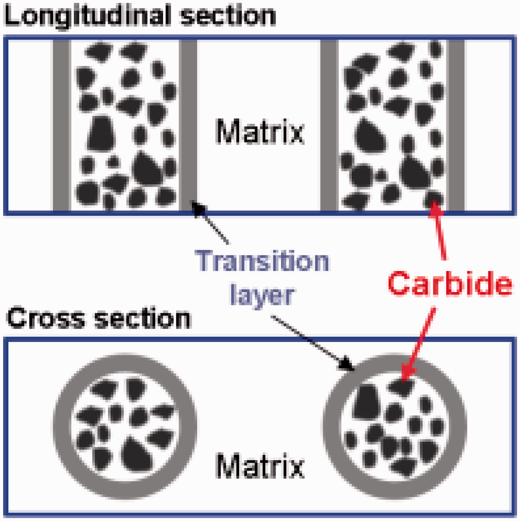
As we know, the presence of a sufficient non-deformed matrix between the reinforcements, which absorbs fracture energy and prevents the formation of cracks, efficiently improves the toughness, especially the resistance to crack propagation, of PRMMCs. The architecture of (Fe, Cr)7C3-Fe/Hadfield steel composites exhibits high particle volume fraction in some areas of the bulk material and other unreinforced areas between these composites, which can efficiently blunt cracks. Thus, not only do reinforcements sufficiently strengthen the matrix but they also improve the toughness of the material.
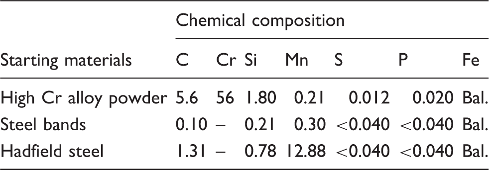
Chemical composition of the starting materials (wt%).
Preparation
The (Fe, Cr)7C3-Fe/Hadfield steel composites were prepared according to the following procedure. A Hadfield steel mold was first produced in rectangular shape, as shown in Figure 2(b). A number of holes were inversely drilled (Diameter 3.25 mm) on both sides, with different target distances between the holes. The flux-cored welding wires were passed through the holes on both sides and then firmly fixed to the mold (Figure 2c). The mold was then inserted into the graphite mold (Figure 2d). All dimensions of the mold are indicated in Figure 2.
3D images of the flux-cored welding wires (a), hadfield Steel mold (b), preform (c), and graphite mold (d) used in the experiment.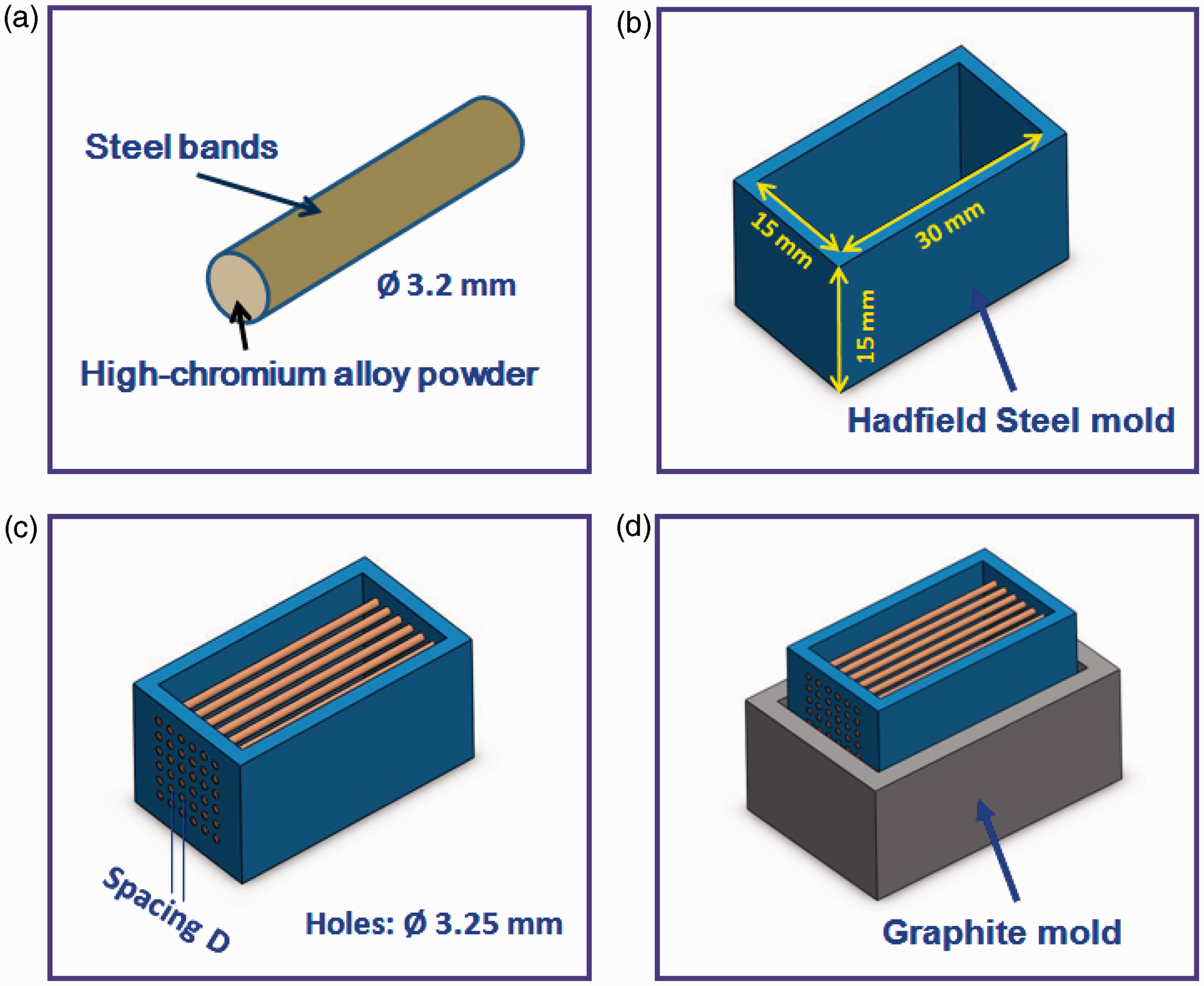
Molten Hadfield Steel was produced in a medium-frequency induction furnace and poured into the mold at 1500℃. The specimen was immediately covered with quartz sand to avoid crack generation, and was cooled down to room temperature. After 24 hours, the as-cast samples were subjected to heat treatment at 1050℃ for 3 hours with a modest flow of argon in a horizontal tube furnace (model GSL1400; Hefei Kejing Materials Technology, Anhui, Hefei, China), and finally specimens were water quenched. Further comparative investigation was carried out using the two specimens: (Fe, Cr)7C3-Fe/Hadfield steel composite and Hadfield steel.
Characterization
After being polished with diamond paste and etched with a 2% Nital solution, the microstructure of the specimen was examined using a JSM-5800 scanning electron microscope (SEM; JEOL, Tokyo, Japan) equipped with an energy dispersive X-ray spectroscopy (EDS). The X-ray diffraction (XRD) data were recorded on a PW1730 X-ray diffractometer (Philips, Eindhoven, The Netherlands) with morochromateel Cu Kα radiation at 40 KV and 40 mA in the 2θ range of 10–90°.
Microhardness of the specimens was measured according to ASTM: E384-11e1, which is the standard test method for Vickers Hardness of metallic materials. Macro-hardness of samples were measured according to ASTM: E18-12, which is the standard test method for Rockwell Hardness of metallic materials.
Abrasive wear and impact toughness test
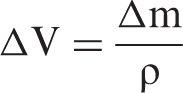
The bulk composites specimens were cut to the size of 6 (Diameter) × 25 mm for the abrasive wear test. The test was carried out on an ML-100 wear test machine (Xuan Ke Testing Machine Manufacturing Co. Ltd., China). The abrasive wear resistance were tested according to JB/T 7506-1994, which is the mechanical industry standard of China. Abrasion tests were carried out using a pin-on-disc apparatus. The particle size of the alumina abrasive paper was 600 mesh. A 20-N load was used. The relative wear resistance (β) was used to evaluate the abrasive wear properties of the (Fe, Cr)7C3-Fe/Hadfield steel composites. This can be obtained by first computing the abrasive volume using the equation
The wear test was repeated at least three times for each sample.
The impact toughness tests were performed on a JB-30A impact toughness tester. The size of V-shaped samples was 10 mm × 10 mm × 55 mm.
Results and discussion
Microstructure
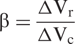
Figure 3 shows the SEM micrograph of the (Fe, Cr)7C3-Fe/Hadfield steel composite. As Figure 3(a) shows, after heat treatment at 1050℃ for 3 hours, the high-chromium alloy powder in the flux-cored welding wires melted and chromium carbide was generated. The unmelted steel bands of (Fe, Cr)7C3-Fe were isolated from the Hadfield steel matrix. Figure 3(b) shows the SEM micrograph of the diffusion layers between the Hadfield steel matrix and (Fe, Cr)7C3-Fe bars. The micrograph indicates that the thickness of the diffusion layers ranges from about 10 µm to 20 µm. The results of EDS analysis of the interface area of the matrix and (Fe, Cr)7C3-Fe bars reveal the presence of four elements: carbon, chromium, manganese, and iron. The presence of these elements indicates that metallurgical bonding is essential in improving the mechanical properties of Hadfield steel composites. The microstructure of the reinforcement phase within the composite is shown in Figure 3(c) and (d). The microstructure is typical of the structure of high-chromium cast iron bars with proeutectic austenite dendrites and interconnected eutectic cells composed of (Fe, Cr)7C3 carbides and austenite.
The micrograph of the (Fe, Cr)7C3-Fe/Hadfield steel composite: (a) cylindrical reinforcement, (b) interface, (c) proeutectic austenite dendrites, and (d) interconnected eutectic cells.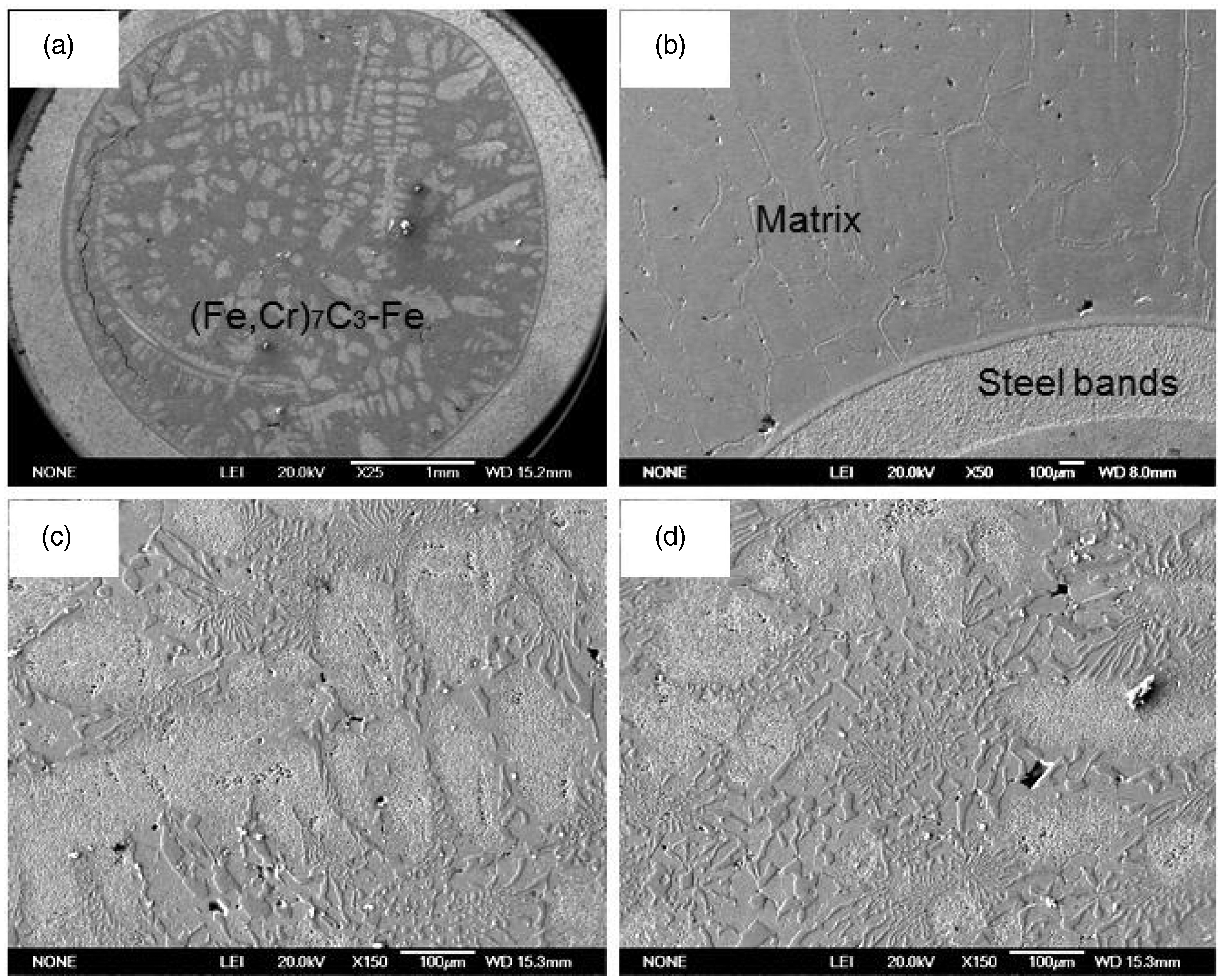
To confirm the reinforcement phases present in the composite, X-ray diffraction analysis was performed. As Figure 4 shows, austenite and (Fe, Cr)7C3 carbides are predominant phases in the reinforcing bar of the composites. The presence of these phases proves that the retained austenite in the reinforcing cores results in higher hardening that further increases the hardness of the composites.
XRD pattern of the reinforcement bar of the composite.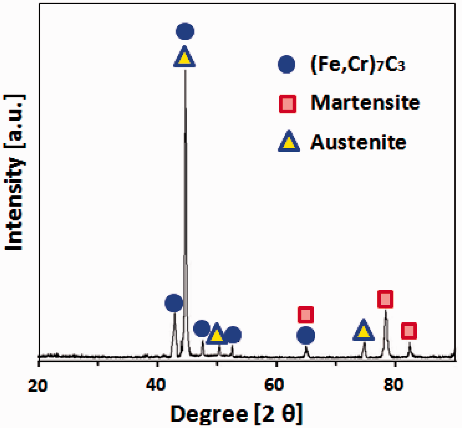
Microhardness
Figure 5 shows the microhardness value of the sample measured across the transition region from the center of the reinforcement bar to the matrix.
XRD pattern of the reinforcement bar of the composite.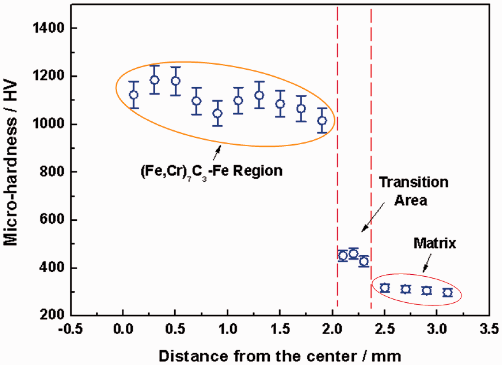
The average microhardness of the matrix is about 300 HV, which further increases to 450 HV in the transformation area and reaches about 1200 HV in the (Fe, Cr)7C3-Fe bundle region. The microhardness values of the (Fe, Cr)7C3-Fe region do not change considerably. The average microhardness value of the (Fe, Cr)7C3-Fe region in the specimen is about 1200 HV as a result of the simultaneous presence of austenite and (Fe, Cr)7C3 carbides. A higher hardness was achieved with the presence of a large number of (Fe, Cr)7C3 carbides at the center of the bars.
Abrasive wear resistance
The relative wear resistances of the Hadfield steel and (Fe, Cr)7C3-Fe/Hadfield steel composite are comparatively shown in Figure 6 as a function of applied load. Under a 5-N load, the specimen has a wear resistance of 1.6, which is higher than that of Hadfield steel, which is 1. Thus, the (Fe, Cr)7C3 particulates have an important role in the improvement of the mechanical properties of the composite. The composite shows better wear resistance across various loads.
The microhardness of the sample measured across the transition region from the center of the reinforcement bar to the matrix.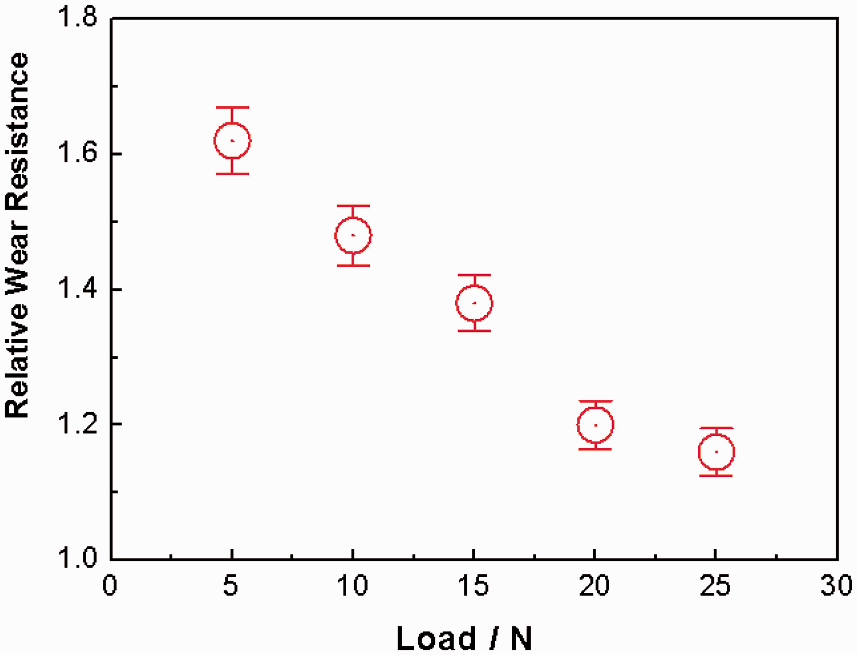
The wear morphologies of the composites under a 5-N load are shown in Figure 7. Some wear marks/grooves can be seen in the reinforcement zone of the (Fe, Cr)7C3-Fe and Hadfield steel matrix (Figure 7). Microcutting and microploughing may be the main reasons for the loss of weight in the composite.11,12 Two main factors improve the wear resistance of the (Fe, Cr)7C3-Fe/Hadfield steel composite. The first factor is the high hardness of the (Fe, Cr)7C3-Fe bar in the matrix. The second factor is the formation of a work hardening layer in high-manganese steel during the wear process. The wear resistance mechanism is due not only to the higher hardness of the (Fe, Cr)7C3-Fe bundle but also to the excellent work hardening ability of the Hadfield steel matrix.
Schematic representation of the wear resistance mechanism (a) and SEM results for the composite after the abrasive wear test under a 5-N load: Hadfield steel matrix (b), interface (c), and (Fe, Cr)7C3-Fe adequate (d).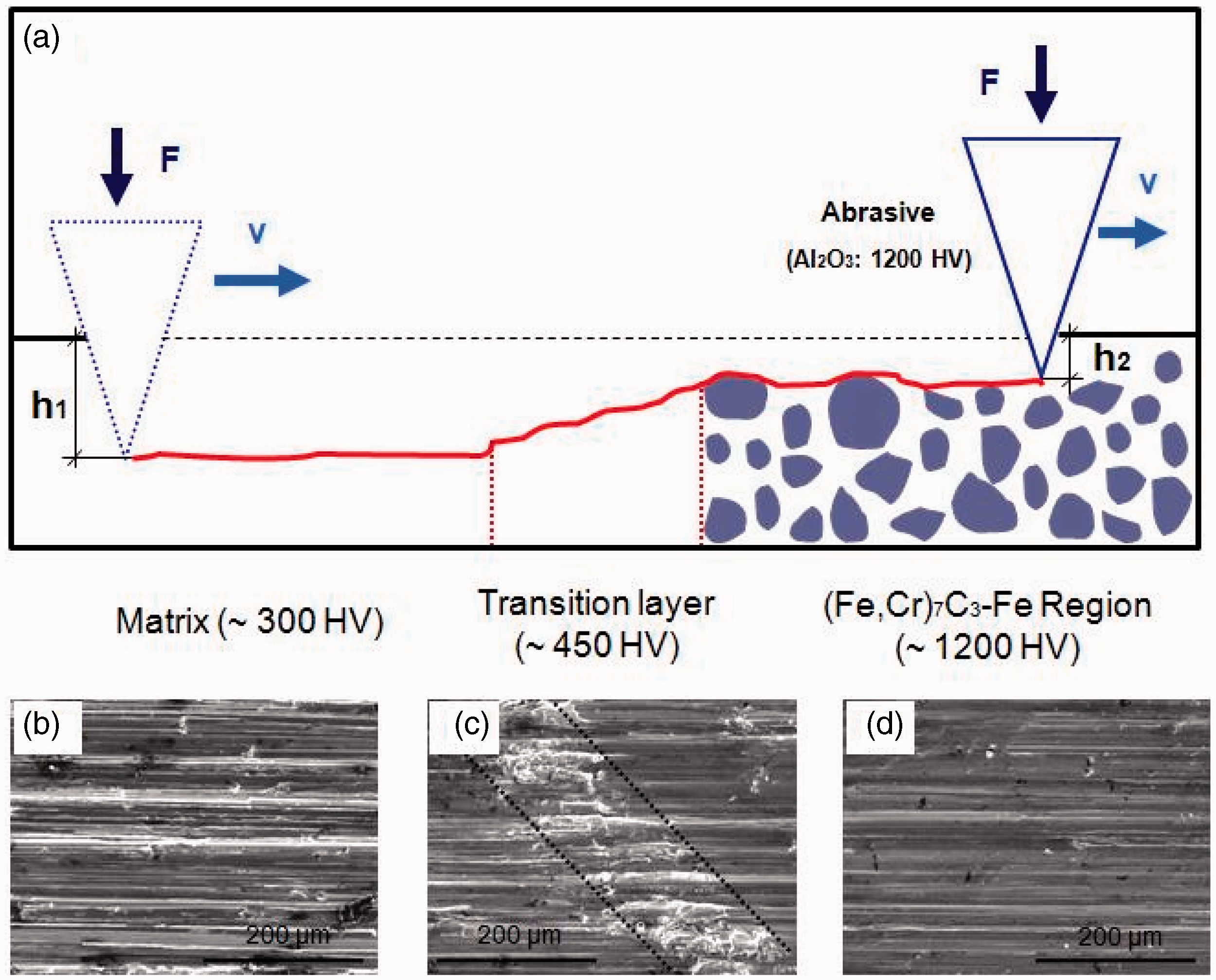
Impact toughness
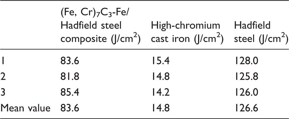
The impact toughness of (Fe, Cr)7C3-Fe/Hadfield steel composite, Hadfield steel and high-chromium cast iron.
To better explain the fracture mechanism, SEM fractographs of the specimens tested under dynamic conditions are shown in Figure 8.
Fracture morphology of (Fe, Cr)7C3-Fe/Hadfield steel composite (a), interface between (Fe, Cr)7C3-Fe and Hadfield steel matrix (b), hadfield steel matrix (c), and (Fe, Cr)7C3-Fe bar (d).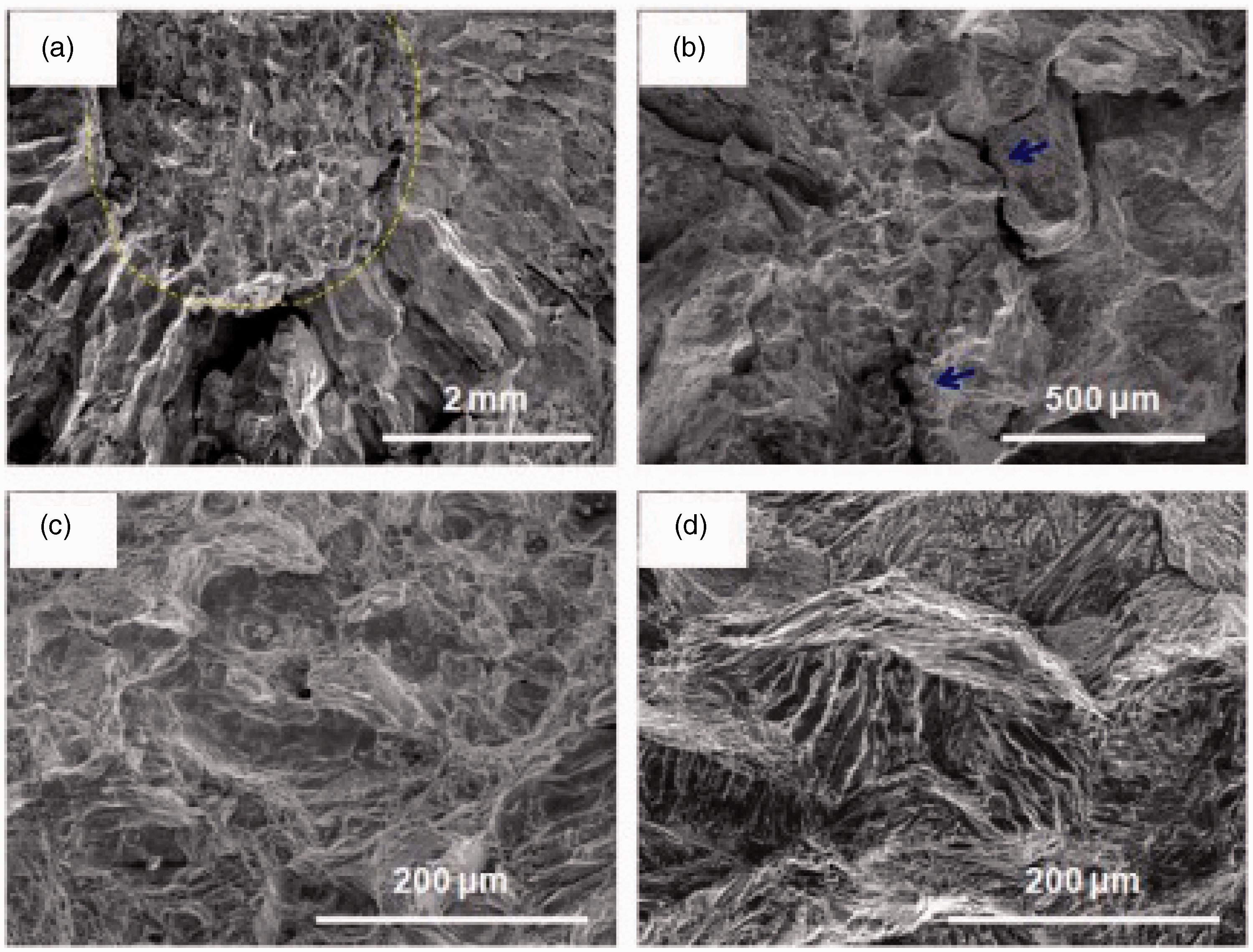
Two distinct surface morphologies were observed in different regions across the fracture surface: cleavage facets and dimples. On one hand, the fracture surface of the Hadfield steel matrix exhibits some large and small dimples (see Figure 8c), which reveals ductility during the impact test. The large dimples are nucleated in the primary carbides or inclusions. On the other hand, in terms of (Fe, Cr)7C3, the fractured feature of the (Fe, Cr)7C3-Fe region displays brittleness, which results in the formation of fracture planes (see Figure 8d). River patterns and fibers can be observed in the cleavage facets, which indicate a mixed ductile-brittle fracture mode. The morphology of the interface between (Fe, Cr)7C3-Fe and Hadfield steel is shown in Figure 8(b). The interface features many microcracks, which are marked by blue arrows in the figure. However, these microcracks are not observed in the other part of the composite. They occur at the boundaries and lead to stress release, which results in increased toughness. 10 Furthermore, the microcracks cause the deflection of the main crack, which also contributes to an increase in toughness.
The fracture model of the (Fe, Cr)7C3-Fe/Hadfield steel composite is greatly changed by altering the particle distribution. The difference of the particle distribution leads to variation of the residual stress and strain hardening, which also affects the fracture behavior of the composites.
The residual stress and strain hardening level near a (Fe, Cr)7C3 particle is higher in the (Fe, Cr)7C3-Fe/Hadfield steel composite than in the conventional uniform particle-reinforced composite because of the smaller distance between the particles in the bar. High stress and strain–hardening conditions in the matrix are detrimental to the fracture properties of the conventional uniform particle-reinforced composite. Nevertheless, the higher residual stress and strain hardening level in the bars do not decrease the overall fracture toughness of the (Fe, Cr)7C3-Fe/Hadfield steel composite. By inference, the deformation characteristics of the matrix between the bars have a more important role in the fracture performance of the (Fe, Cr)7C3-Fe/Hadfield steel composite. Larger patches of matrix exist between the bars of the (Fe, Cr)7C3-Fe/Hadfield steel composite because of the cluster of (Fe, Cr)7C3 particles in the bars. The maximum residual stress and strain hardening level in the matrix near the bar is similar to that near a single (Fe, Cr)7C3 particle in the conventional uniform particle-reinforced composite. Moreover, the volume of the matrix with a low residual stress and strain hardening level is larger in the (Fe, Cr)7C3-Fe/Hadfield steel composite. Hence, the matrix between the bars has a higher ductility, and the onset of void nucleation is delayed in the (Fe, Cr)7C3-Fe/Hadfield steel composite. In addition, the low stress level in the matrix can reduce the constraint ahead of a crack tip from the plane strain to plane stress conditions, which is good for fracture toughness. 13
The above discussion leads to the conclusion that the good fracture toughness of (Fe, Cr)7C3-Fe/Hadfield steel composite is mainly a result of the presence of microcracks in the interface and the high toughness of the Hadfield steel matrix. Moreover, the higher residual stress and strain hardening level in the bars do not decrease the overall fracture toughness because the deformation characteristics of the matrix between the bars have a more important role in the fracture performance of the (Fe, Cr)7C3-Fe/Hadfield steel composite.
Conclusions
In this paper, (Fe, Cr)7C3-Fe/Hadfield steel composites were fabricated through in situ synthesis with infiltration casting and subsequent heat treatment. The microstructure, microhardness, impact toughness, and wear resistance of the composites were studied. The results show the following:
The (Fe, Cr)7C3-Fe/Hadfield steel composites can be fabricated through in situ synthesis with infiltration casting and subsequent heat treatment. Austenite and (Fe, Cr)7C3 carbides are predominant phases in the reinforcing bar of the composites. The best wear resistance of the (Fe, Cr)7C3-Fe/Hadfield steel composites was 1.6 times higher than that of a Hadfield steel under a 5-N load. The wear resistance mechanism results not only in response to the higher hardness of the (Fe, Cr)7C3-Fe bundle but also in the excellent work hardening ability of the Hadfield steel matrix. The fracture mechanism is in the ductile-brittle fracture mode. The good fracture toughness of the (Fe, Cr)7C3-Fe/Hadfield steel composite is mainly a result of the presence of microcracks in the interface and the high toughness of the Hadfield steel matrix. Moreover, the direction of the crack propagation changes and the energy of the crack are offset by plastic deformation of the Hadfield steel matrix.
Footnotes
Acknowledgements
The project supported by Postdoctoral Science Foundation of China (No. 2014M552488). The authors also acknowledge the financial support from the National High Technology Research and Development Program of China (No. 2013AA031803).
Conflict of interest
None declared.