






Abstract
The compression properties of three-dimensional angle-interlock woven E-glass fabric/vinyl ester composite material along thickness direction under quasi-static (0.001 s−1) and high strain rates (800, 1600, and 2700 s−1) were investigated with finite element method and compared with those in experimental. The finite element method model was based on the three-dimensional woven composite microstructure. It was found that the compressive properties are sensitive to strain rate both in finite element method and experimental. The finite element method results showed good agreements with that of experimental in stress–strain curves and fracture morphologies. The obvious strain rate sensitivity of the compression properties and failure modes of three-dimensional angle interlock composites was both verified with the finite element method model and results in experimental. The compressive stiffness and maximum compressive stress increased with the strain rate while the failure strain showed an opposite trend. The failure mode is mainly in shear failure. The compressive failure mechanisms have been analyzed from the different components of the three-dimensional woven composites.
Keywords
Introduction
As the reduced manufacturing cost and the increased demand for lightweight composite structures, three-dimensional (3D) woven composite material, as one kind of textile composite materials, becomes more popular in aerospace and high speed vehicles because of the high ratio of impact damage tolerance/weight.1,2 Compared with the unidirectional and two-dimensional (2D) laminated composites, although the in-plane properties of 3D woven composites are inferior, the mechanical properties along thickness direction are superior to 2D laminates due to the reinforcing fiber tows along the thickness direction in 3D woven preform. Specifically, the impact resistance and damage tolerance of 3D woven composites in the thickness direction are excellent.3–5
Because the 3D woven composites may encounter various external loadings during their use as structural components, a comprehensive understanding of their mechanical performance is essential for the engineering design. Tensile tests of 3D woven composites revealed that the mechanical properties and the volume fraction of binder yarns affect the final fracture mode significantly.6,7 The most important significance of binder tows lies in improving the delamination resistance of 3D woven composites when subjected to through-thickness compression or impact loading. Kuo et al.8,9 studied the compression-induced damage in 3D orthogonal woven composites, assessed the influence of surface loops on the damage behavior, and examined the effect of weaving processes on the compressive behavior of 3D woven composites. Mahadik and Hallett 10 showed that distortions in the internal architecture such as yarn waviness can reduce the in-plane properties of the corresponding composites, especially under compression loading. Ji et al. 11 studied the damage of 3D orthogonal woven composite circular plate under quasi-static indentation and high strain rates transverse impact. Bahei-El-Din and Zikry 12 analyzed the deformation fields and kinematics of woven composites under impact loading using finite element method (FEM). Sun et al. 13 studied the impact compression of 3D woven composites. Rudov-Clark and Mouritz 14 found that the tensile fatigue properties and residual fatigue strength (after one million load cycles) of 3D woven composites were lower than that of 2D woven composites. This indicated that the binder yarn properties and volume fraction had significant effect on the fatigue behaviors of 3D woven composites. But very few people study the compression properties of 3D angle-interlock woven composite material along thickness direction under high strain rates with FEM. It is very important to design the structure of the composite materials, and it can give new insights into the damage and failure mechanisms under dynamic loading conditions.
In this paper, a finite element model based on the microstructure of 3D woven composite was established to analyze the compression responses of the 3D angle-interlock woven composites under quasi-static and high-strain-rate compression. The compression failure mechanisms of the 3D woven composites were explained with the stress distribution and damage evolution along each yarn system and resin matrix. Furthermore, the failure modes and detail damage process of each component (i.e. weft and warp yarns, stuffer yarns, and matrix) were obtained to analyze the compression damage mechanisms. The experimental results were employed for the comparisons between FEM numerical results and those in experimental. The FEM developed in this study was validated by the good agreements in the stress–strain curves and fracture morphologies under different strain rates between numerical and experimental results.
Materials and experimental
Materials preparation
The 3D angle-interlock woven preforms consist of three sets of yarns, named as stuffer yarns, weft yarns, and warp yarns separately. The stuffer yarns and weft yarns are arranged in an orthogonal array, with the warp yarns passing through the thickness of the whole preform at a certain angle to interlock with the fillers.
15
The construction of the 3D E-glass woven perform is shown in Figure 1. The vinyl ester resin was injected into the 3D angle-interlock woven preforms by Resin Transfer Molding (RTM) technique and fully cured into 3D woven fabric composites. The total thickness of the final 3D woven composites was 3.0 mm, with the fiber volume fraction of about 40%. The composite was cut into compressive coupons with an in-plane size of 9.0 × 9.0 mm2.
Architecture of 3D angle-interlock woven preform.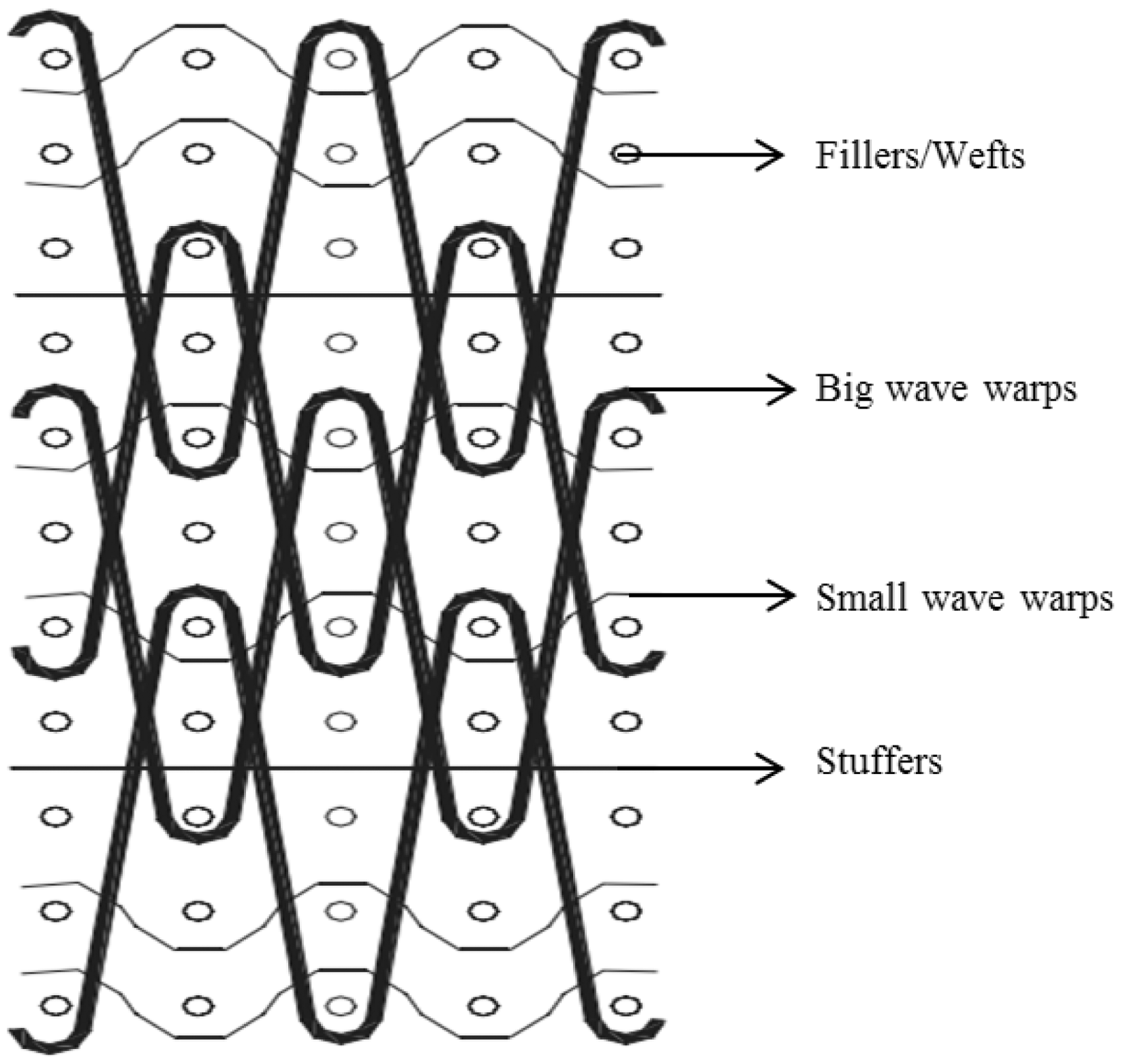
Compression tests under different strain rates
A modified split Hopkinson pressure bar (SHPB) system was designed to conduct compression tests on 3D angle-interlock woven composites under high strain rates ranging from 800 to 2700 s−1. Meanwhile, quasi-static compression tests were done on MTS 810.23 apparatus for comparison with that under high strain rates. Schematic diagram of quasi-static compression test is presented in Figure 2. During all the quasi-static tests, the speed of the indenter was 1 mm/min, which indicated a constant stain rate of approximately 0.001 s−1. All the tests were carried out along the thickness direction of the composites. Three identical tests were performed under each strain rate and average value was calculated to obtain the ultimate strain–stress curve. More details about the experiments can be seen in Rudov-Clark and Mouritz.
14
Schematic diagram of quasi-static compression test.
In impact compression tests, the coupon was sandwiched between two horizontal bars, i.e. incident bar and transmission bar. The schematic diagram of the SHPB system is shown in Figure 3. The compression stress wave was generated between the incident bar and the strike bar which was driven by the gas gun. Two strain gauges were mounted on the incident and transmission bars to record the stress waves propagating along the two bars. Based on the experimental apparatus, two steel bars were established to sandwich the composite coupon in the middle. Two steel bars were constrained to move only along the axial direction to achieve 1D linear elastic stress wave propagation. The compression stress wave was applied on the end far away from the coupon of one bar. Figure 4 shows the voltage–time curves captured by the strain gauges under the strain rate of 800 s−1.
Schematic diagram of SHPB testing system. Voltage–time curves at the strain rate of 800 s−1.

FEM modeling of the 3D woven composites under compressions
The full-size geometrical model of 3D angle-interlock woven preform was established based on the assumption that the cross section of E-glass fiber tow is rectangular, as shown in Figure 5(a) with the fillers, warp yarns, and stuffers shown in Figure 5(b) to (d), respectively. The cross section dimension of each yarn system is presented in Table 1. The total fiber volume fraction of the model is about 44.9%, which is close to the actual content in the coupon.
Geometrical model of 3D angle-interlock woven preform.
Cross section dimensions of three sets of fiber tows.

Engineering constants of the E-glass fiber tow.

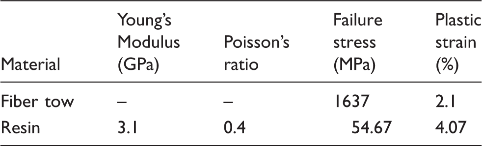
Elastic–plastic property of resin and E-glass fiber tow.
During real impact compression tests, the stress–strain response of the composite coupon under various strain rates could be obtained from the input and output waves based on one direction linear elastic wave propagation theory. The compression stress wave used in the FE model was calculated from the experimental results, which is described in detail in equation (1)
The quasi-static compression tests were conducted by inserting the composite coupons between two flat steel plates. The bottom one was fixed with the top plate moving downward at a constant speed. Thus, two steel bars were replaced with two steel flat plates in the FEM simulation. Furthermore, velocity boundary conditions were adopted to simulate the compression behaviors under quasi-static.
All of the simulations were fulfilled with the commercial FEM software package ABAQUS/explicit. The 3D angle-interlock woven composite was meshed using C3D8R element. The total number of element in the final model was 198,846, including 63,588 elements in the preform and 135,258 in the resin.
Results and discussions
FEM results
The comparisons of the stress–strain curves calculated from the FEM model and experimental are shown in Figure 6. It can be observed that the compression behaviors of 3D angle-interlock woven composite are strain rate dependent. The detail sensitivity of compression parameters on the strain rate is listed in Table 4. It is shown that the maximum stress and compression modulus increased with the increasing of the strain rate, while the failure strain decreased with the increase of the stain rate. As shown in Figure 6, the slope at the initial stage of the stress–strain curve under quasi-static loading is relatively low, which could be attributed to the incomplete contact between the coupon and the two plates. The subsequent linear elastic portion essentially characterized the compression properties of 3D angle-interlock woven composite. It implied that the failure strain under quasi-static loading is slightly greater than that of 3D angle-interlock woven composite in actual service. So a much bigger difference for the failure strain between the FEM results and the experiment results can be found. Both maximum stress and compression modulus under quasi-static and impact compressive loading are nearly same. It can also be concluded that the FEM model developed in this paper is valid since there was a good agreement between the FEM and the experimental, i.e. stress–strain curves, fracture morphologies, and failure modes under different strain rates.
Comparison of compression stress–strain curves along thickness direction between FEM and experimental. Mechanical properties of the 3D woven composites at various strain rates.

Damages of the composite coupons at various strain rates
Figure 7 presents the microscopic images of 3D woven composite under various strain rates. Figure 8 shows the final failure modes of the composite under various strain rates with FEM. The damage morphology observed from Figure 8 is similar with the result got from the experiment. It can be found that the compression failure mode of 3D angle-interlock woven composite is strain rate dependent. Composite coupons are damaged more severely under higher strain rates. Shear failure bands can be clearly viewed from the fracture morphologies of composite shown in Figure 8. The shear failure bands go through the thickness with a slant angle ranging from 20° to 50° to the weft direction. The number of shear failure bands and the slant angle (θ) decreases with the increasing strain rate.
The microscopic images of 3D woven composite under various strain rates. (a) Quasi-static, (b) 800 s−1, (c) 1600 s−1, (d) 2700 s−1. Failure mode of 3D woven composite under various strain rates. (a) 0.001 s−1, (b) 800 s−1, (c) 1600 s−1, (d) 2700 s−1.

It can also be observed from the stress distribution of the composite coupon that the stress is more uniform under 0.001 s−1 than those under high strain rates. The reason lies in the low loading rate of the pressing plate during quasi-static loading. In addition, there is enough time for the stress to be transferred and distributed along the whole specimen. Whereas the stress wave propagates fast and there is not enough time for it to transfer when the composite coupon is subjected to impact loading in the SHPB system. The stress varies greatly for different parts due to the unique construction of 3D angle-interlock woven composite. Specifically, stress in weft fiber tows differs greatly from that in the adjacent resin matrix especially under quasi-static loading. This difference can easily lead to debonding of the interface between the fiber tows and the resin. Cumulated debonding cracks can connect each other and eventually result in delamination between different layers. The stress discontinuity between the fiber tows and adjacent resin is not obvious under the strain rate of 800 s−1 but it becomes more distinct as the strain rate increases. This is the reason why the delamination occurs when the strain rate reaches a specific value. As have been assumed in FEM model that the interface between the fiber tows and the resin is perfect, there is no delamination damage being presented. Therefore, compared with the shear damage, delamination damage is negligible under quasi-static loading.
Damage analysis of each component
It is difficult to capture the damage initiation and damage evolution in the specimen in experimental. The FEM model contributes to the specific damage history of each constituents of the specimen. The failure modes of the resin and three kinds of fiber tows are discussed as follows. Although strain rate dependency of the compression properties had been confirmed, the stress distribution and damage evolution in different constituents of 3D woven composites under different strain rates was similar to some extent. Here only the compression failure mode of the 3D angle-interlock woven composite under the strain rate of 1600 s−1 is presented.
Failure mode of the resin
Figure 9 shows the damage evolution in the resin. Shear band gradually forms and becomes the dominant damage mode as the stress wave propagates. There were two shear bands that were formed in the final fracture morphology. The two shear bands eventually formed a “V” shape instead of being parallel to each other. The stress distribution nephogram at 103 µs shows that the left shear band starts to emerge in the thickness direction, with the right one subsequently appearing. When the left shear band propagated along line AB, the stress in the composite redistributed and the material adjacent to it could slide along line AB. As a result, the composite was finally divided into two parts by the left shear band. For the portion in the right, the compressive stress was applied on the top surface and its bottom surface was supported by the steel plate or the transmission bar. A shear band along line BC occurred as the compressive loading continued. In the end, a “V” shape fracture line was formed by the two shear bands.
Damage evolution in the resin. (a) 0 µs, (b) 77 µs, (c) 103 µs, (d) 111 µs, (e) 129 µs, (f) 146 µs.
Failure mode of warps
As shown in Figure 1, there are two kinds of fiber tows in the warp yarn system with different function. Based on the crimp length along the thickness direction, they are defined as big-wave warp yarns and small-wave warp yarns, respectively. The principal role played by the big-wave warp yarns is to keep the integrity of different layers of weft yarns. The small-wave warp yarns hold the weft yarns in the same layer in position. Figures 10 and 11 show the stress distribution and damage evolution of the big-wave and small-wave warp yarns separately. Stress nephograms at 77 and 103 µs in Figures 10 and 11 show the big difference in stress transmission in the two kinds of warp yarns. For big-wave warp yarns, the inclined portions through thickness play a predominant role in carrying the external compression load. Stress distribution nephograms at 111 and 129 µs in Figure 10 indicated that the main damage mode along the big-wave warp yarns was shear damage at similar positions with the slant portions as shown by arrows. Stress distribution of small-wave warp yarns was significantly different from that of big-wave warp yarns, with the primary load-carrying locations lying in the in-plane portions or horizontal portions. As the composite coupon was subjected to compression loading along the through-thickness direction, all the in-plane portions of the fiber tows underwent extension in the transverse direction due to the Poisson’s ratio effect. Fiber tows failed at the positions when the failure strain in tension was reached. Stress distribution nephograms at 129 and 146 µs in Figure 11 exhibit element deletion in simulation. The tension failure positions are marked by arrows. The element deletion in the inclination portions proved the existence of shear loading. Furthermore, the elements in the in-plane portions near to the corners were damaged more seriously. This is because fiber tows located near to the corners sustain a combined action of shear load and tensile load. Comparison between the failure mode of the two kinds of warp yarns suggested that small-wave warp yarns have superior compression resistance in the whole 3D woven composite.
Damage evolution in big-wave warp yarns. (a) 0 µs, (b) 77 µs, (c) 103 µs, (d) 111 µs, (e) 129 µs, (f) 146 µs. Damage evolution in small-wave warp yarns. (a) 0 µs, (b) 77 µs, (c) 103 µs, (d) 111 µs, (e) 129 µs, (f) 146 µs.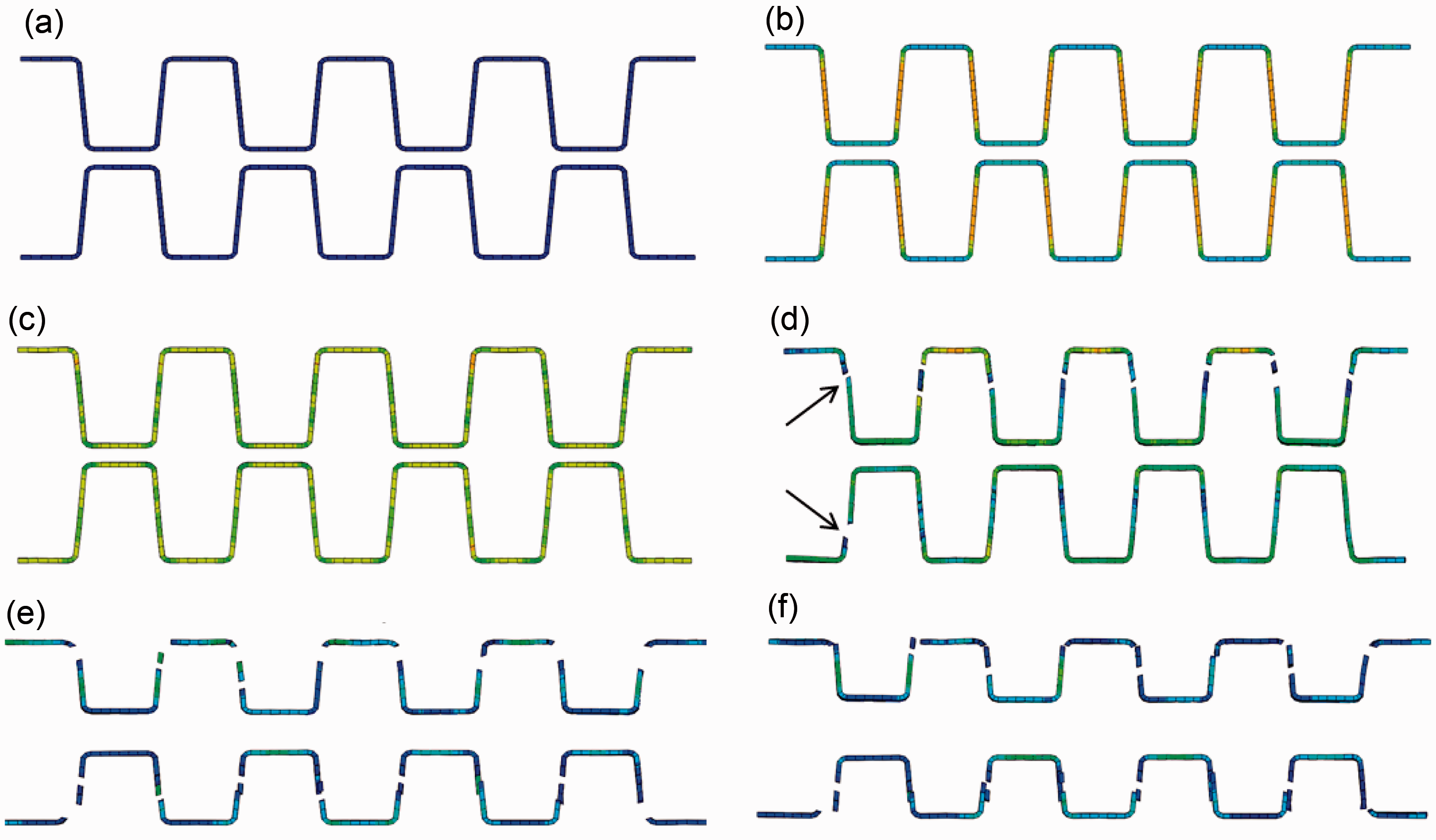
Failure mode of weft yarnsc
Because of the Poisson’s ratio effect, weft yarns were under tension state in the direction vertical to the compression loading. Shear damage and sliding of resin matrix transferred shear load to the weft yarns. As presented in Table 3, the shear modulus of fiber tows is less than in-plane tensile modulus. The shear damage in the weft yarns is shown in Figure 12 where the position of the shear bands in the weft yarns coincides with that of the resin matrix.
Damage evolution in weft yarns. (a) 0 µs, (b) 77 µs, (c) 103 µs, (d) 111 µs, (e) 129 µs, (f) 146 µs.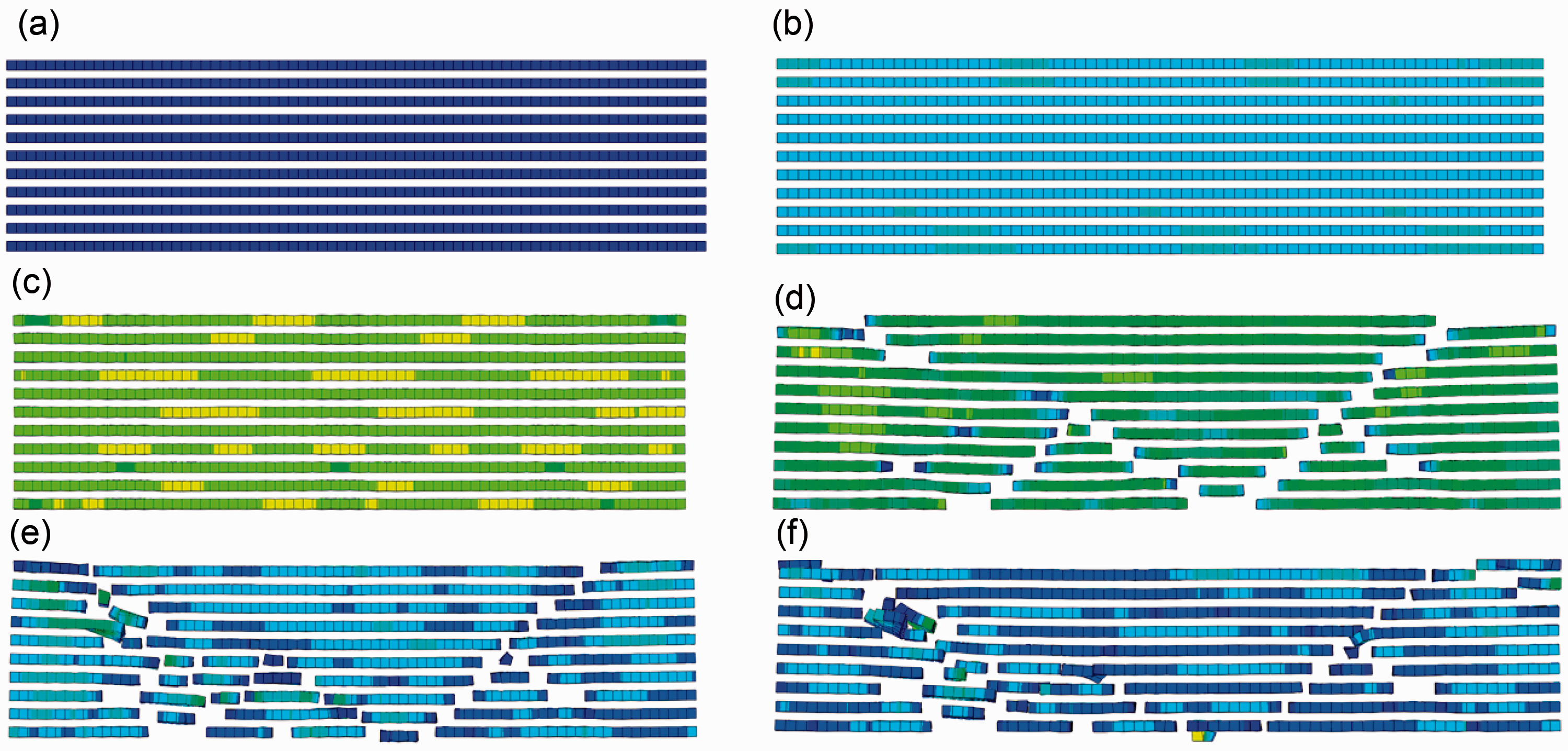
Failure mode of stuffers
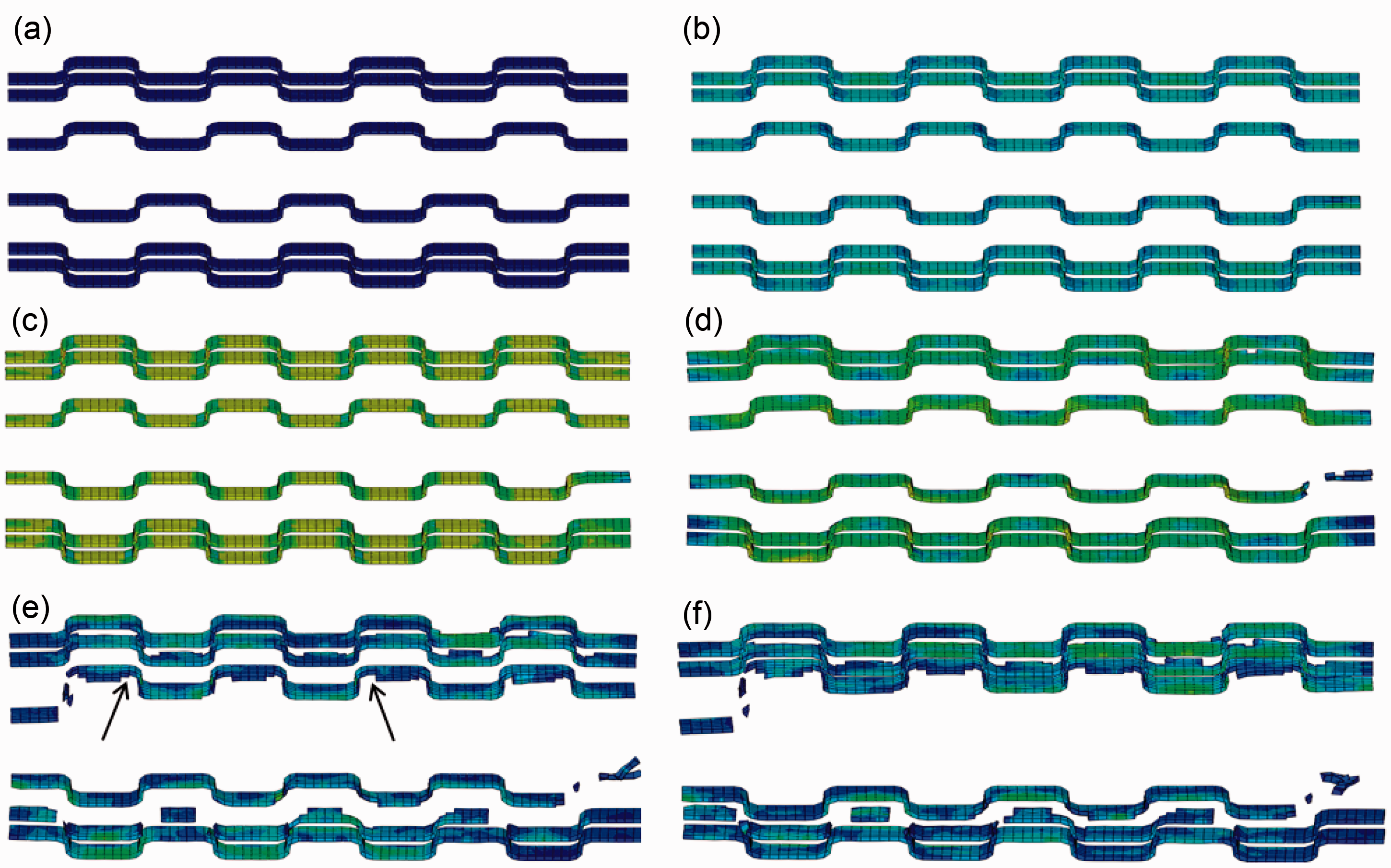
Figure 13 shows the damage evolution in stuffer yarns. It can be clearly observed that the damage in the bottom two layer was much serious than that of the top two. The main reason can be attributed to the fact that bottom layers of stuffer yarns are just located at the shear bands of the matrix. The undamaged stuffer yarns suggested that they contributed less to the compression load than the warp yarns and weft yarns.
Damage evolution in stuffer yarns. (a) 0 µs, (b) 77 µs, (c) 103 µs, (d) 111 µs, (e) 129 µs, (f) 146 µs.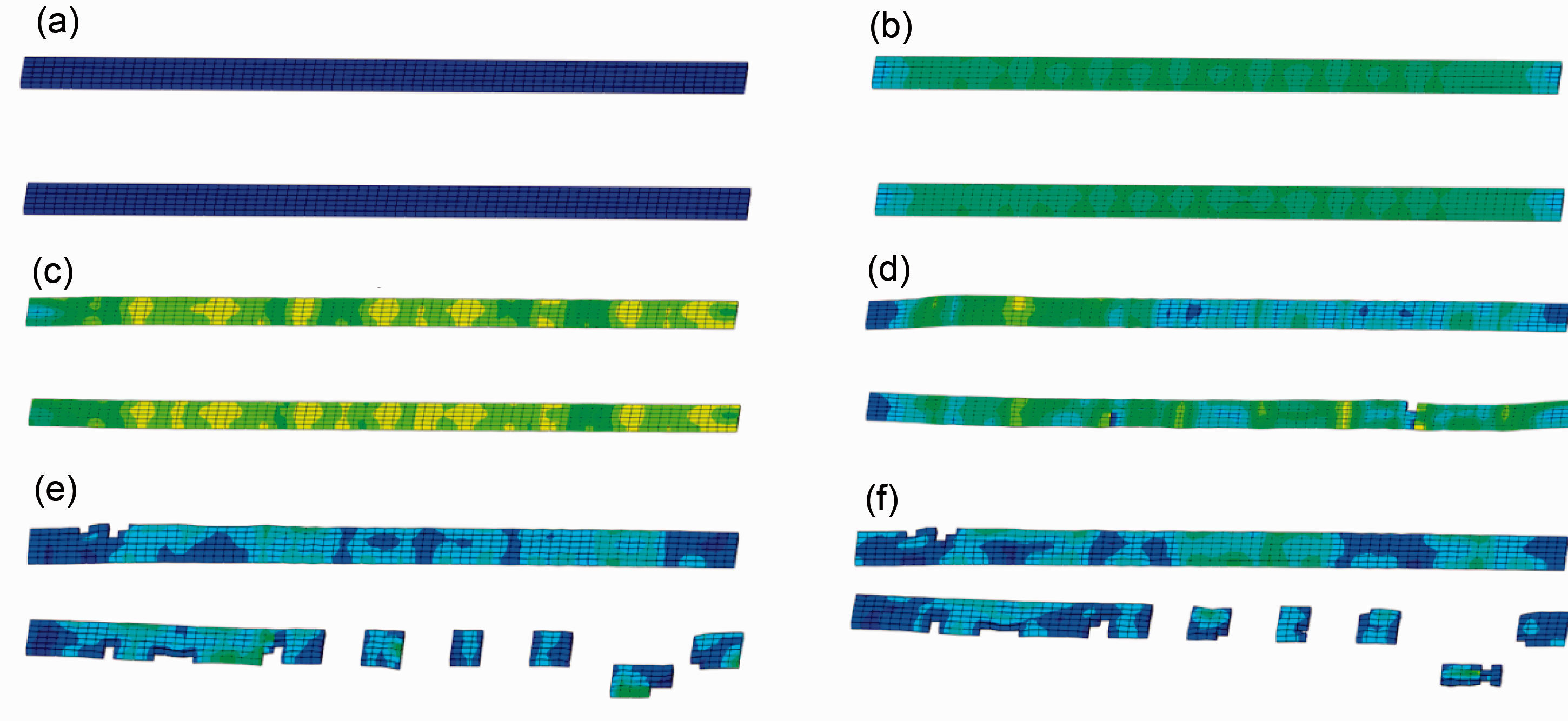
Conclusions
The compression damages of 3D angle-interlock woven composite under quasi-static and high strain rate compressions were investigated with FEM and validated with the experimental. The FEM results showed good agreements with that of experimental in stress–strain curves and fracture morphologies. The obvious strain rate sensitivity of the compression properties and failure modes of 3D angle interlock composites was both verified with the FEM model and results in experimental.
The fracture mechanisms of 3D woven angle interlock composite were interpreted with the compression damage analyses of each component, including the fracture. It was found that shear damage was the main failure mode of the woven composite under compression loading. The in-plane tension failure also contributed to the final failure of the 3D woven composite to some extent. The failure modes of resin matrix and fiber tows can provide constructive suggestions for the manufacturing and design of 3D angle-interlock woven composite with excellent through-thickness compression properties, such as adopting resin and fiber tows with higher shear strength.
Footnotes
Acknowledgements
The authors acknowledge the financial supports from the National Science Foundation of China (No. 11272087) and National High-tech R&D Program of China (863 Program) (No. 2012AA03A206). The financial supports from the Foundation for the Author of National Excellent Doctoral Dissertation of PR China (No. 201056), the Fok Ying-Tong Education Foundation (Grant No. 141070), the Keygrant Project of Chinese Ministry of Education (No. 113027A), Shanghai Science and Technology Innovation Action Plan (No. 12521102400; No. 12dz1100407), and the Fundamental Research Funds for the Central Universities of China are also gratefully acknowledged.
Conflict of interest
None declared.
Funding
This research received no specific grant from any funding agency in the public, commercial, or not-for-profit sectors.