
Abstract
This paper deals with mode II interlaminar delamination properties and failure mechanisms of composite laminates in three-point end-notched flexure (3-ENF) tests under fixed cyclic loading. The results for fracture toughness, fatigue driving force and delamination propagation behaviours of three different types of carbon and E-glass fibre/epoxy resin-reinforced composite laminates are evaluated and compared with each other for providing an insight into fatigue damage development in composites and for constituting a fundamental basis for the development of a characterization model. A new characterization formulation is presented for mode II interlaminar delamination propagation based on controlling fatigue stress. Finally, the model is applied to experimental data, demonstrating the practical and effective use of the proposed model. It is shown that fatigue-driven strength for mode II interlaminar delamination propagation can be obtained realistically from experimental data using the new formulae.
Keywords
Introduction
Composite materials are being increasingly used in structures due to the superior specific stiffness and strength. However, because of initial flaws formed during processing and assembling, delamination might occur and propagate under cyclic loading, and this could lead to catastrophic structure failure. Previous research1–12 has shown that delamination predominantly appeared in mode I (tensile) and mode II (shearing). Strain energy release rate (SERR) based on fracture mechanics was adopted in characterizing mode I/II fracture behaviours albeit predominantly under static loading. Actually, a precondition for composites application in engineering structures (especially in primary aerospace structures) is the need to determine crack propagation properties in mode I/II delamination under cyclic loading for assessing damage tolerance and residual life of composite structure. A large body of research13–19 exists to determine and to characterize crack propagation behaviour of fibre/epoxy-reinforced composites in mode I delamination. There is growing interest in crack propagation properties in mode II interlaminar delamination of composites subjected to cyclic loading. Trethewey et al. 20 implemented three-point end-notched flexure (3-ENF) tests on unidirectional carbon/epoxy laminates through the fixed displacement control method to investigate stable mode II delamination propagation behaviour. Experiments showed that mode II delamination size grew with the SERR in a power law, and the relationship between the delamination propagation rate and the SERR followed the Paris model. After this, the fixed displacement control method was applied in 3-ENF tests for investigating environmental effects21,22 on mode II delamination propagation behaviour and microscopic structure23–25 of fibre/epoxy composite laminates. Due to the unstable nature of delamination growth, 7 four-point end-notched flexure (4-ENF) was presented for stable mode II delamination propagation behaviour. 10 Nevertheless, the adverse effects of significant specimen shortening and variation in clamping limited its validity and application. 26
In practice, the 3-ENF test has received considerable attention recently in light of the simple loading condition and small interlaminar friction resulting from the compression of the middle loading pin. It is worth noting that the fixed load control in 3-ENF test holds superiority over the fixed displacement control in terms of much simpler test procedure and constant stress level at crack tip, etc.27,28 Thus, there is a need for understanding the fixed load control method on 3-ENF test and for developing a characterization model to determine the mode II delamination propagation performance of fibre/epoxy composite structures for engineering designs, particularly in the aerospace field, which is the focus of this paper.
Fatigue-driven model for mode II delamination propagation behaviour of 3-ENF beam
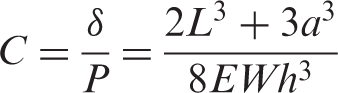
According to the Euler beam theory and fracture mechanics,
29
the compliance C and SERR of a 3-ENF beam are, respectively
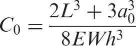
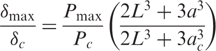
For an initial crack size a0, from equation (1), it is possible to have the initial compliance C0 as
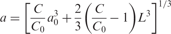
From equations (1) and (3), one has
Again, from equations (1) to (2), it is possible to allow
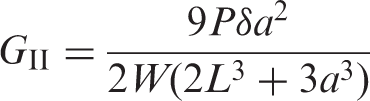
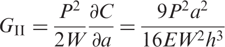
Analogous to the J-integral or energy release rate G in fracture mechanics, the concept of an SERR is introduced and interpreted as the driving force and criterion for mode II interlaminar delamination propagation. From equation (5), the SERR
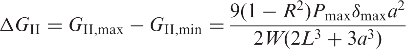
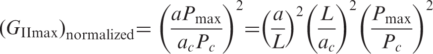
Generalizing fatigue load-based fracture data is a time-consuming and expensive process, thus it is desirable to examine how fatigue-driven SERR characterization can be deduced from static loading test. From equation (5), the fatigue-driven force (i.e. normalized SERR) can be written as
Again, from equation (1), it is possible to show
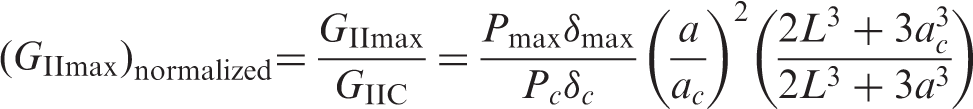
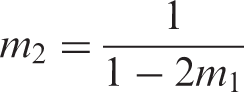
Substituting equation (9) into equation (8) shows
Equation (10) characterizes the fatigue-driven force pattern based on static fracture properties and it is obvious that in the case of a fixed cyclic loading with constant amplitude and at a stress ratio of R, the driving force monotonically increases with the delamination length a.
Again, analogous to the Paris model
30
in fracture mechanics, the crack growth rate da/dN versus
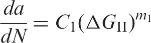
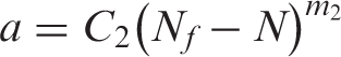
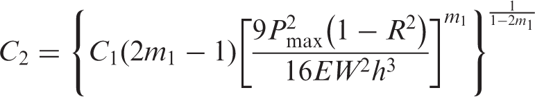
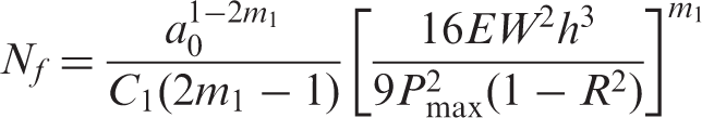
Substituting equation (6) into equation (11) and integrating yields
ENF experiments and discussion
Three types of specimens were manufactured using the resin transfer moulding technique and constructed out of the following unidirectional FRP laminate, respectively:
GFRP1 Laminate: GFRP (glass-fibre-reinforced plastic) laminate made from Rc10.800/6002 (i.e., Rc10 800 glass fibre and 6002 bisphenol A-type epoxy resin). GFRP2 Laminate: GFRP (glass-fibre-reinforced plastic) laminate made from Rc10.800/3232 (or Rc10 800 glass fibre and 3232 mid-temperature curing epoxy resin). CFRP Laminate: CFRP (carbon-fibre-reinforced plastic) laminate made from T300/5405 (namely, T300 carbon fibre and 5405 modified bismaleimide resin).
Mechanical property. 31
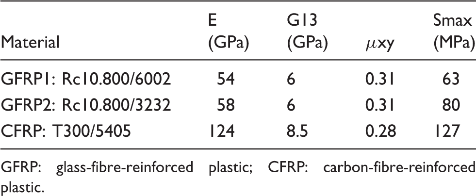
GFRP: glass-fibre-reinforced plastic; CFRP: carbon-fibre-reinforced plastic.
All 3-ENF tests were conducted on MTS 880-50 kN servo-hydraulic machine in a dry state at room temperature. The specimens were supported on two cylindrical rollers to simulate simply supported boundary conditions, and the bending loads were applied at the mid-span by a remotely controlled hydraulic jack. For the fracture toughness tests, the level of applied load was monitored with a load cell and the deflections were measured by dial gauges at a displacement rate of 2 mm/min. Unlike significant stick-slip behaviour resulted from the interlaminar friction effect in 4-ENF tests,
10
no observable amount of stick-slip behaviour was detected during 3-ENF tests, consistent with the efforts of previous work.
33
The load–displacement Load–displacement curves from 3-ENF test ((a) GFRP1, (b) GFRP2 and (c) CFRP).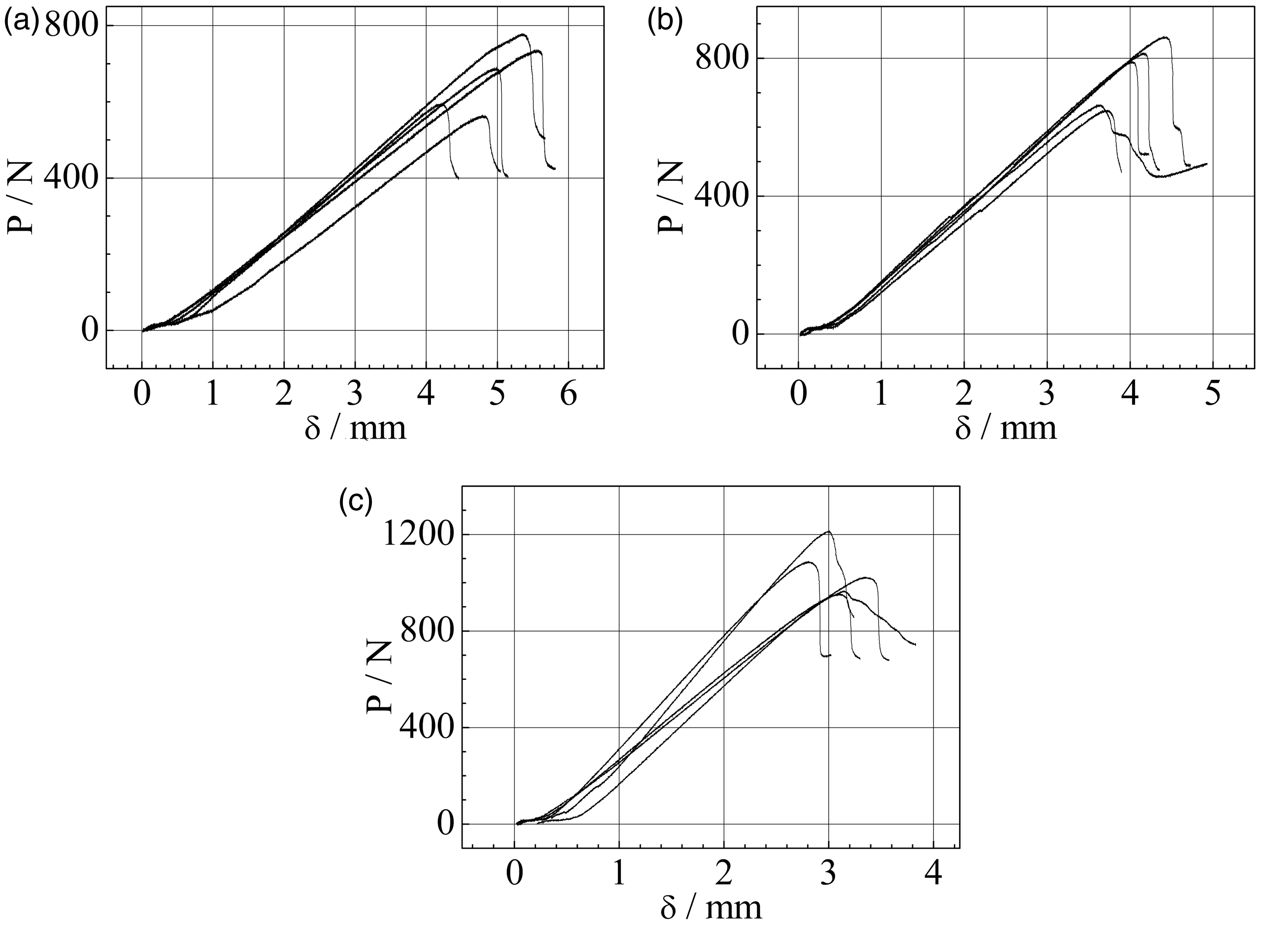
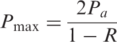
Fixed load control (or cyclic loadings of constant stress amplitude) was applied on all mode II interlaminar delamination propagation tests at a stress ratio of 0.1 and at a frequency of 10 Hz for avoiding the hysteresis heating effect.
34
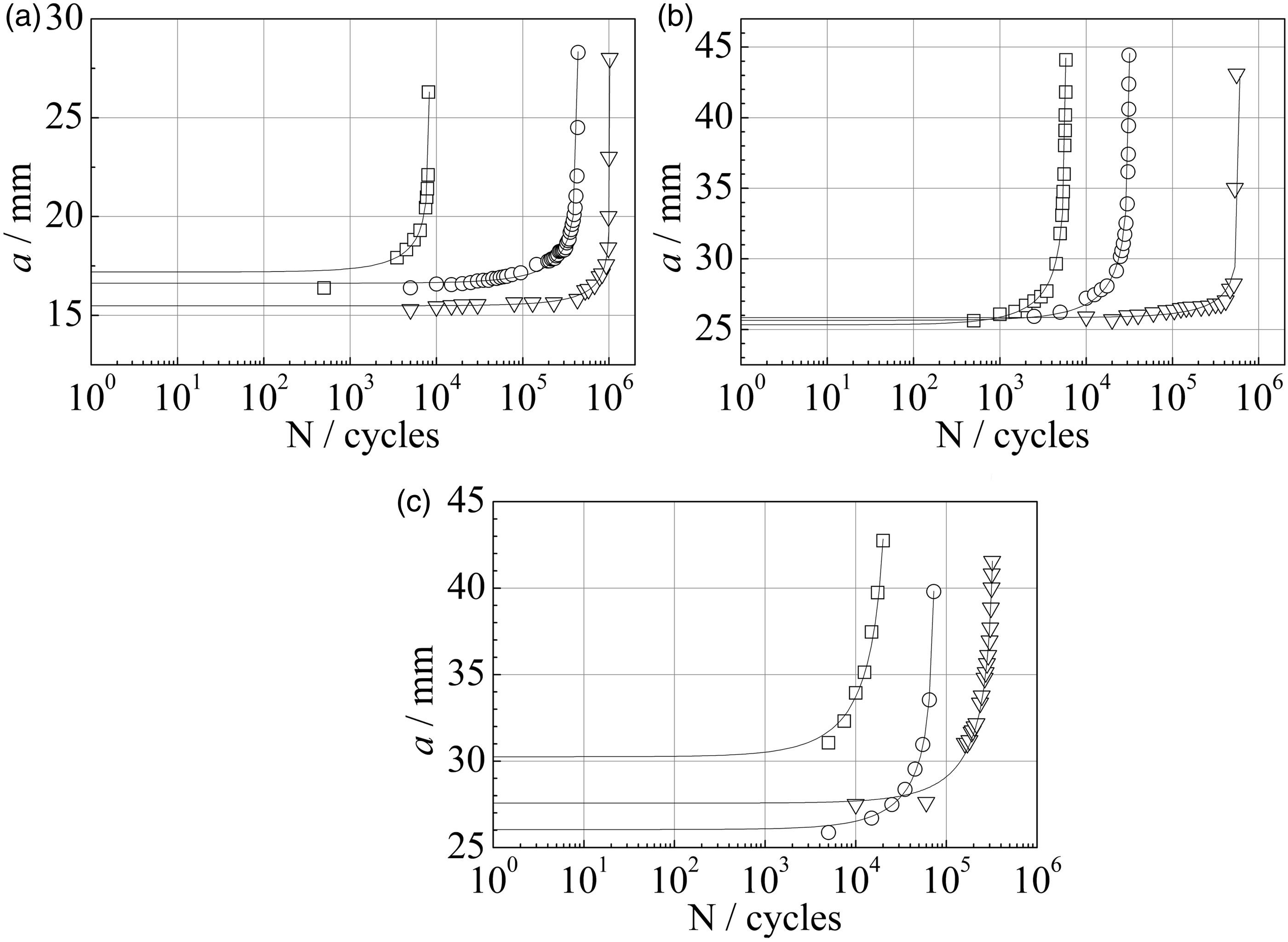
Owing to the difference of bending rigidity between different types of specimen, the cyclic loadings with constant amplitude were monitored from the loading response and controlled through adjusting the span distance between two cylindrical rollers during tests. So, the span distance was placed to be 80 mm for GFRP1 specimens while it was 100 mm for GFRP2 and CFRP specimens. In order to avoid the shifting of the specimen towards the notched end to cause a lower delamination resistance than the actual value, it is essential to add a restraint on the specimen during tests.20,34,35 Thus, a longitudinal restraint was placed on the specimen by bonding a smooth and slender wood pin, which is so flexible that the stress concentration is negligibly small at the bonding location on the specimen (Figure 2). WZHD0850 long focal-length optical telemicroscope with 0.01 mm measurement accuracy was implemented to measure the delamination length a on side surfaces of specimen. The measurement was given at a fixed interval of cyclic loading, until a sinusoidal pattern of the loading response cannot be sustained by test machine, due to decreasing bending stiffness of a specimen. The experimental data of delamination length versus number of stress cycles Shifting restraint in 3-ENF test. Interlaminar delamination size versus cycle number of constant cyclic loading ((a) GFRP1, (b) GFRP2 and (c) CFRP).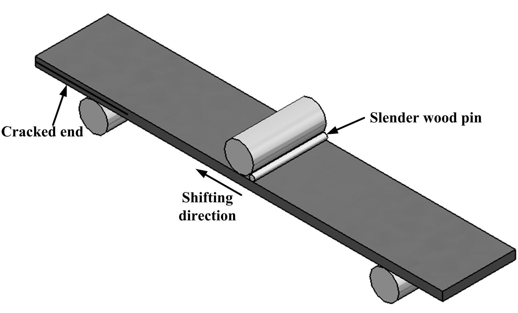
A 20 × optical microscope was employed to conduct the fractographic analysis of fracture specimen (Figure 4). From Figure 4, it is obvious that the mode II interlaminar delamination propagation region on fracture surface of CFRP shows ‘hackle patterns’, while the mode I pre-crack area appears ‘river markings’, demonstrating the fractographic feature of mode II delamination propagation resulted from shear stress distinct from that of mode I delamination propagation arising from tensile stress. The fractographic feature in this paper has a good agreement with those in literature.
12
Fracture surface for CFRP.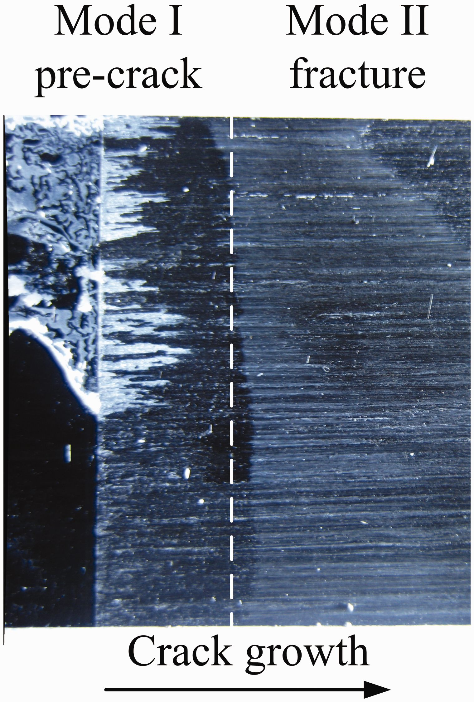
Application to a practical case
Fracture toughness and coefficient of variation.
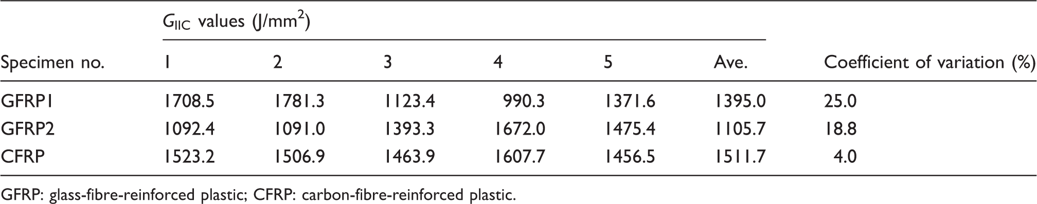
GFRP: glass-fibre-reinforced plastic; CFRP: carbon-fibre-reinforced plastic.
Experimental propagation values of Driving force curves at different loading ratios ((a) GFRP1, (b) GFRP2 and (c) CFRP).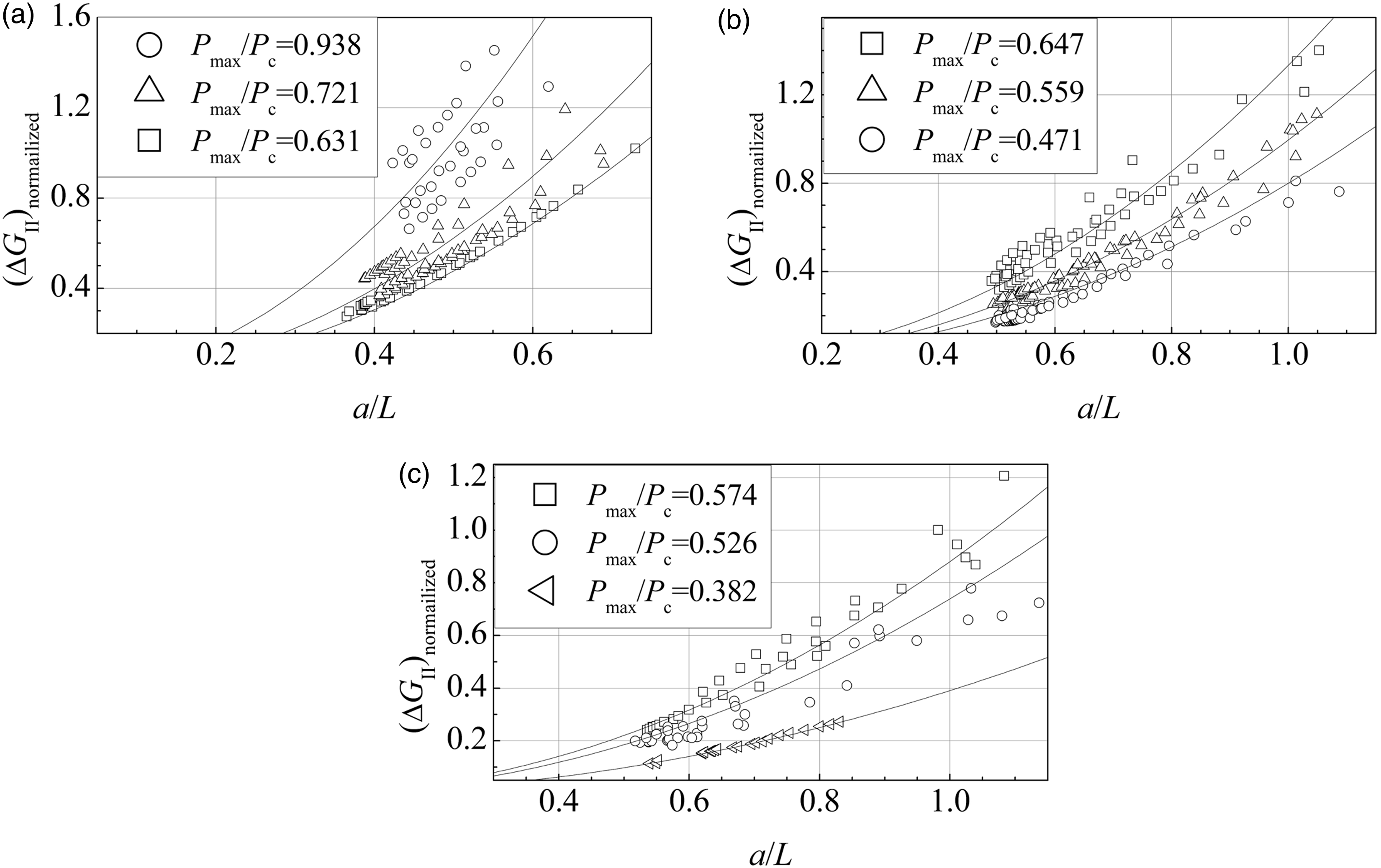
Delamination propagation curves.
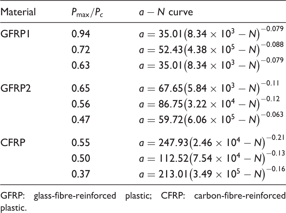
GFRP: glass-fibre-reinforced plastic; CFRP: carbon-fibre-reinforced plastic.
From the experimental data Interlaminar delamination propagation rate versus SERR ((a) GFRP1, (b) GFRP2 and (c) CFRP).


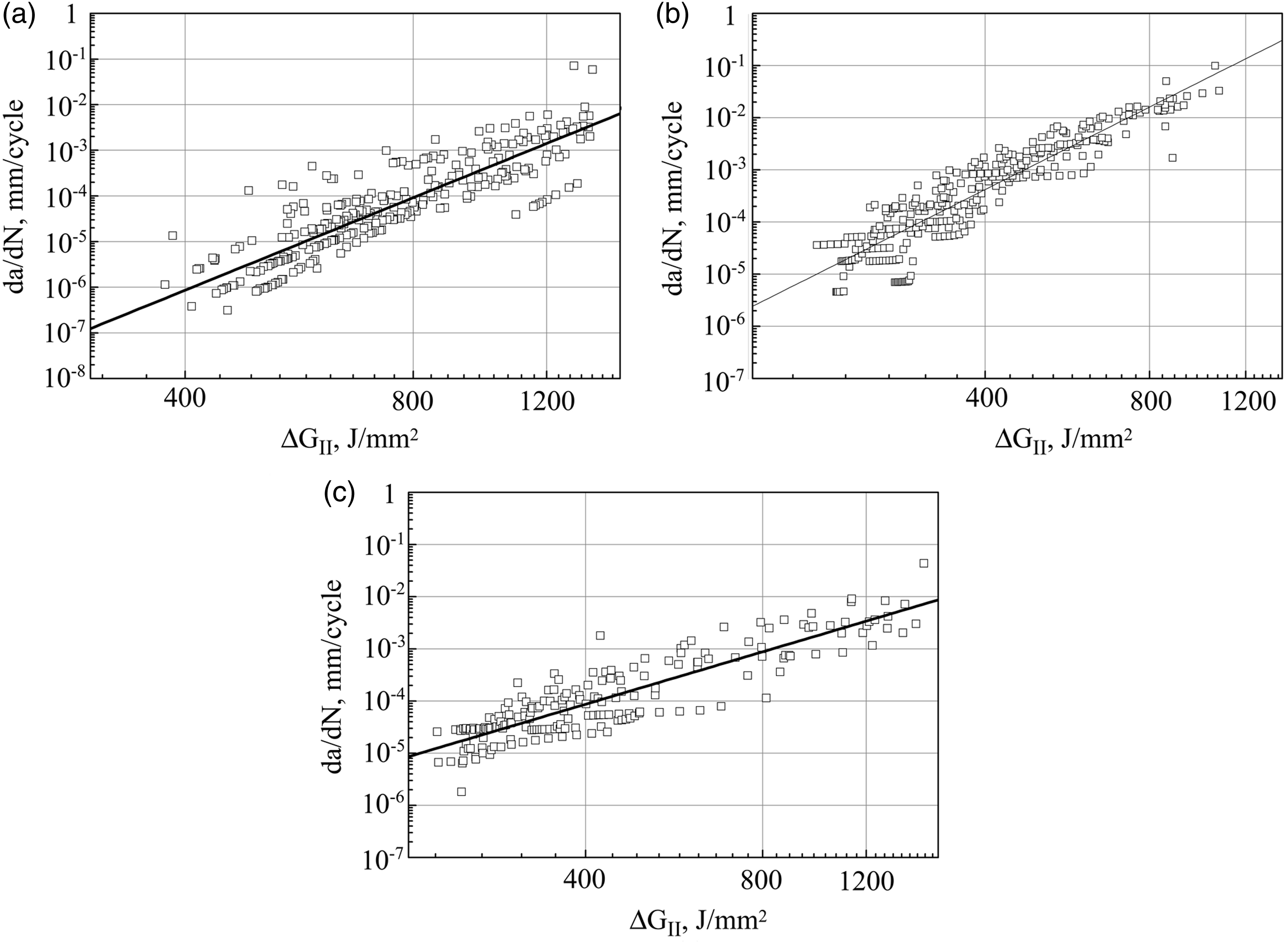
Equations (16) to (18) are shown in Figure 6(a) to (c). From this, it is evident that there is good agreement between the experimental data and the predicted curve. Thus, it is argued that the mode II delamination propagation rate models of equations (11) and (12) have adequately and logically characterized the physical characteristics and the phenomenological quantitative laws. It should be noted despite the accuracy of the proposed characterization method by equation (12) in characterizing delamination propagation, mode II delamination fatigue behaviour in terms of delamination propagation rate scattered. This is probably due to the inevitable microscopic deficiencies during manufacturing. Therefore, fatigue data are still needed for reliably fitting the Paris model parameters, which deserves further studies into it.
Conclusion
The focus of this paper has been to present mode II interlaminar delamination properties of composite laminates by using three-point end-notched flexure (3-ENF) tests under fixed cyclic loading to understand the failure mechanisms and to model the degradation process of mode II interlaminar delamination strength. Three different types of carbon and E-glass fibre/epoxy resin-reinforced composite laminates were used for the determination of mode II fracture properties. The results for the mode II fracture toughness, fatigue-driven force and delamination propagation behaviours were evaluated and compared with each other. The damage and failure mechanisms of the composite laminates have been discussed.
Some significative experimental and analytical results are obtained. A practical model for mode II interlaminar delamination strength and life prediction is presented. Its applicability for estimating mode II interlaminar delamination model using minimal experimental data has been proven successfully. Close correlation is achieved between the predictions and the actual experimental results.
Footnotes
Conflict of interest
None declared.
Funding
This project was supported by the NSFC (no. 51375033) and ASFC (no. 20095251024).