
Abstract
Enhanced tribological and location-specific properties achieved in functionally graded metallic composites make them potential materials for futuristic engineering components. The present investigation aims on the processing of homogenous and functionally graded Al matrix composites reinforced with SiC particles of 23 µm average particle size by gravity and centrifugal casting techniques. The sizes of the primary aluminium and eutectic silicon phases are finer towards the outer periphery due to the higher solidification rate. Functionally graded Al–SiCp composite rings produced by centrifugal casting show higher concentration of SiCp towards outer periphery, followed by a gradient transition region and the particle depleted zone. Particle agglomerates formed due to partially wetted particles associated with voids and gas porosities segregate towards the inner periphery. The higher concentration of reinforcement particles near the outer periphery in FGM enhances the hardness and wear resistance in rotary and reciprocating wear studies. Centrifugal cast alloys show enhanced wear resistance than the gravity cast specimen due to fine grains of primary aluminium and eutectic silicon. The rotary and reciprocating wear test shows the adhesive and abrasive type wear mechanisms.
Keywords
Introduction
Functionally graded materials are comparatively new class of advanced inhomogeneous composite materials, where the material composition and/or the microstructure are locally varied to regulate the physical and mechanical properties within a component at specific locations.1–3 The phenomena of graded structures are prevalent in nature such as bones, wood and in some of the conventional engineering materials. The concept of making FGM was proposed in the mid-1980s in Japan. The developments of FGM are still in its infancy stage and there are scopes for developing wide varieties of FGM genuine for thermal protection systems for specific engineering applications such as in aerospace, automotive industry, defence, etc. due to their high-temperature surface resistance, thermal properties, increased bonding of ceramic–matrix interface and increased fracture toughness. 4 Most of the FGM studies are multiphase composite materials where the volume fraction of reinforcement particles or phases varies continuously from one location to the other within a component or structure leading to the formation of controlled non-uniform microstructure with continuous change in properties. Processing of FGM and their engineering components with gradient properties are very much exigent and has a lot of technological relevance. Out of various processing methods for FGM such as chemical vapour deposition, physical vapour deposition, sol–gel technique, plasma spraying, molten metal infiltration, self-propagating, centrifugal casting, diffusion bonding laser cladding and controlled mould filling, etc. centrifugal casting is the simplest and cost-effective technique for producing large-size engineering components.
Centrifugal casting or rotocasting is a pressure casting technique which is used to produce functionally graded metal matrix composites by the aid of centrifugal force applied in the pool of molten metal for the high quality of the results attainable, particularly for precise control of their metallurgy and crystal structure at specific locations of the cast component by rotating the casting mould. Both horizontal and vertical centrifugal casting methods are used for making FGM. In vertical centrifugal casting method, a centrifugal force applied to a homogeneous semi-liquid composite, (containing ceramics or intermetallic compound particles) drives the formation of the desired gradient, resulting in composition gradient that is produced by the difference in density between the molten metal and the particles under the same centrifugal force in a vertical axis. Mechanical properties of FGM fabricated by this method have been investigated using relatively large samples.5–8 Velhinho et al. produced functionally graded SiCp reinforced aluminium–matrix composites by centrifugal casting and observed that SiCp is partially clustered with some pores due to imperfect wetting of ceramic particles by the molten aluminium alloy. 8 Hence, proper wetting between the particles and the matrix is necessary to reduce particle clustering. A gradient in the microstructure and in the hardness of the centrifugally cast Al alloy is also observed due to the differences in the solidification rates. Sharper gradients in the distribution of the reinforcing particles are obtained in the higher centrifugal speeds and a smoother in the lower speeds. 1
Most of the tribological studies were carried out using pin-on-disc (rotating) wear tester and ball-on-ring tribometer.9–16 The concept of FGM can be effectively used in automobile components such as engine blocks, cylinder liners, piston rings, etc. in which these parts are subjected to wear under reciprocating condition rather than rotary condition. A rotating wear phenomenon alone cannot stimulate the actual wear phenomenon that occurs in reciprocating components. Hence reciprocating wear studies are significant in these components. In reciprocating wear, the pin material is held stationary itself but the counter surface that in contact perfectly undergoes reciprocation, which gives sliding experience in both directions instead of rotation in the case of pin on disc. 17 The rotating as well as the reciprocating wear performance of aluminium alloys and metal matrix composites/FGM not only depends on the service conditions (load, sliding distance, sliding speed, counter surface temperature and roughness of the surface) but also depends upon various material-related mechanical properties (hardness, ductility and toughness) and microstructure.18,19 In aluminium-based alloys and composites, the dominant wear mechanisms found are two-body abrasive wear, adhesive wear, oxidative wear and delamination.
The objective of the present investigation is to process A356 alloy and 10 and 20 wt. % SiCp reinforced 356 Al MMC and FGM using liquid metal stir casting and centrifugal casting techniques and evaluation of microstructure, mechanical properties, rotary and reciprocating wear characteristics. Cast A356 alloys are used as it finds potential applications in diverse fields such as in automotive parts; aircraft fittings and control parts; water-cooled cylinder blocks due to the excellent castability and good weld ability, pressure tightness and excellent resistance to corrosion.
Experimental methods
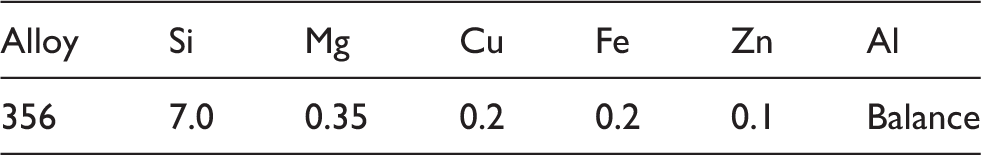
Chemical composition of the 356 Al matrix alloy.
The wear test experiments were carried out both in gravity (homogeneous structure) as well as in centrifugal castings (FGM) in alloys and composites using rotary (pin on disc) and reciprocating wear tests. In the pin-on-disc wear test, the pin specimen surfaces undergo uniform sliding and velocity throughout while the reciprocating wear give sliding experience in both directions where the velocity is maximum at the middle and minimum (zero) at the ends of the sliding distance. Hence the wear rates were also different for the two types of tests. The dry sliding conditions were used for both pin-on-disc and reciprocating wear testing procedure. The surface morphologies of worn-out pin surfaces were evaluated using the stereo microscope to understand the types of wear mechanisms.
Rotating wear test was made using standard pin-on-disc wear testing machine (wear and friction monitor – 20LE) that measures tribological properties such as the coefficient of friction, frictional force and wear volume between two surfaces in contact. Pin-on-disc tribometer consists of a stationary pin holder (6 mm diameter) where the normal load was applied to the pin specimen (6 mm diameter and 30 mm length) by using dead weights with the help of string and special pulley arrangement, which can bear a maximum load capacity of 15 kg (147.15 N). Wear specimens of 6 mm circular cross section were in full contact with the counter body in the entire test duration. The counter surface disc used was En 31, high-carbon alloy steel (165 mm diameter) which possesses a high degree of hardness (63 HRC) with compressive strength and abrasion resistance and material composition of Cu 1.00%, Mg 0.50%, Cr 1.40% and Si 0.20%. A constant sliding distance of 330 m and a velocity of 1 m/s were maintained throughout the tests, and accordingly the track was adjusted to obtaining the specific needs. The tests were continued with the same composition of the material with four different loads of 1 kg (9.81 N), 4 kg (39.24 N), 8 kg (78.48 N) and 12 kg (117.72 N). A photograph of pin-on-disc wear test rig is shown in Figure 1.
Photograph of pin-on-disc wear testing machine.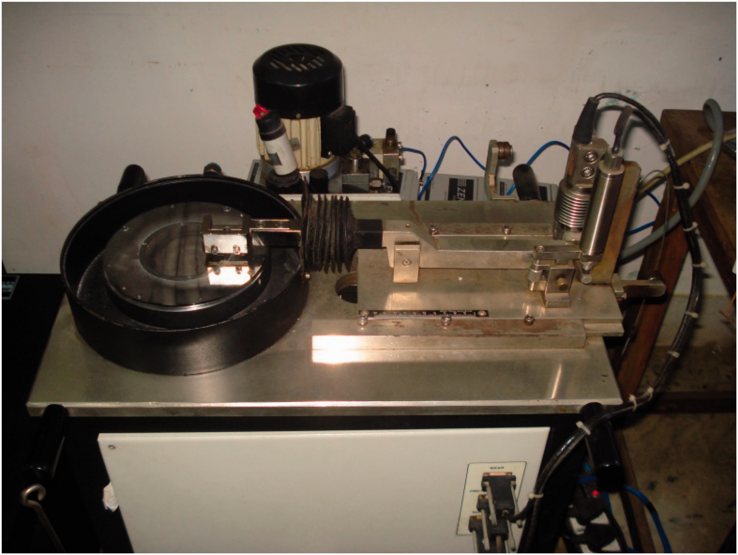
The reciprocating wear and friction setup confirming to ASTM G 133-05 standard was fabricated in-house and the important features, design aspects and operational kinematics are described below. Schematic diagram and a photograph of the fabricated and developed reciprocating wear and friction test rig is as shown in Figure 2(a) and (b). The reciprocating tests were carried out using the heat-treated specimens of 6 mm diameter and 30 mm long, which reciprocates on an En 31 steel counter surface. The length of the wear track was kept 100 mm throughout the experiments, and it can also be varied accordingly. Load on the pin was ensured through a cantilever type lever arm and loading arm mechanism, which was perfectly hinged on a perpendicular column fixed rigidly on the base of the machine bed. Calculated leverage of the loading system was two. The pin was held in the position by a specially fabricated collect type pin holder fixed firmly in the lever arm. The wear test rig design consists essentially of a reciprocating trolley reciprocates on the guide paths in trolley stand under applied load against the specimen through the slider crank mechanism. The trolley was held in the position by fixtures driven by a crank and connecting rod assembly through an AC motor of 3 HP (2.2 kW) whose speed can be controlled precisely (0.1–1 m/s) by using a voltage/frequency controller (V/F controller or drive). A press-fit element was connected to a temperature controller fixed at the bottom of the trolley plate for heating the counter surface to study the effect of heat on the wear rate of the material while the pin reciprocates. A perfect contact of the pin material with the counter body is ensured throughout the tests by polishing the circular cross sections of the pin before every set of test using fine abrasive papers, which is embedded with SiCp. A constant sliding distance of 330 m was kept in all experiments. A frame and housing are also provided to accommodate the pin and counter surface tribo-elements, drives, loading system, temperature controller system and pin holding systems to function the system as a single unit. Reciprocating experiments were executed with a velocity of 0.2 and 0.4 m/s to study the influence of velocity at the wear rate. In reciprocating wear test, seven different loads of 1 kg (9.81 N), 2 kg (19.62 N), 4 kg (39.24 N), 6 kg (58.86 N), 8 kg (78.48 N), 10 kg (98.1 N) and 12 kg (117.72 N) were used. The reciprocating wear rate depends on various parameters such as the mean reciprocating velocity, applied load, the material used and the counter surface temperature as a result of continuous sliding of the pin over it. In both wear studies, wear rates were calculated from the wear loss value by weighing initial and final weight of the pin specimen before and after the test using an electronic balance with 0.1 mg least count.
17
(a) Schematic diagram of the fabricated reciprocating wear test rig and (b) photograph of the developed reciprocating wear test rig.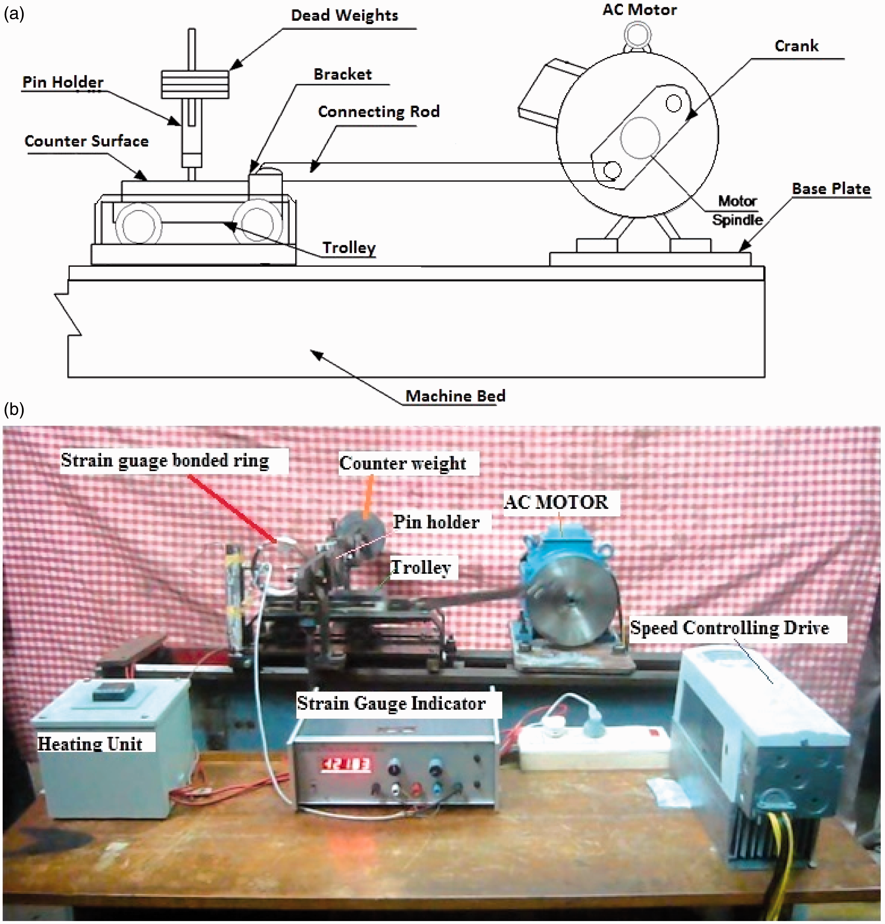
Results and discussion
Microstructural observations
The optical microstructure samples of alloys and composites (A356, A356-10 wt. % SiCp and A356-20 wt. % Sip) were cut from the as-cast gravity solid cylinders and the centrifugal ring castings were polished to reveal the microstructure. The gradients in composition or microstructures are tailorable by varying the processing parameters such as size and initial concentration of particles, centrifugal force, cooling rate, temperature of the mould, pouring temperature and heat transfer between the mould and the melt.1–3 The thickness of particle-enriched zone decreases with increasing pouring temperature and speed of rotation. During centrifugal casting, the segregation of particles due to particle movement is slowed down as a result of decreasing melt temperatures and crowding of particles occurring in progressively narrow zones during solidification.
Figure 3(a) to (c) shows the typical variation in the microstructures of gravity as-cast alloys and composites, respectively. The optical microstructure of base alloy which reveals the structural morphology of primary aluminium and eutectic silicon phase in the matrices is shown in Figure 3(a). A little porosity was observed towards the inner periphery due to the segregation of low-density gases. The presence of uniform columnar Al dendrites as well as eutectic phases are observed at different locations, i.e. from the outer diameter to the inner of the as-cast solid cylinders. The size of the primary aluminium phase has reduced when SiCp reinforcement was added to the matrix, and the size of the eutectic silicon phase is also decreased due to the addition of the particles, as was evident in Figure 3(b) and (c). Since the stirring time is more in 20 wt. % SiCp reinforced composites, some iron intermetallics were found due to the erosion of mild steel impeller in the molten aluminium matrix for a long time. Agglomeration of SiCp was also found in 20 wt. % composites. The above-mentioned microstructures (Figure 3(a) to (c)) show an even distribution of primary aluminium–eutectic phase in case of alloy, particle and aluminium–eutectic phase in the case of A356 metal matrix composites.
Optical microstructure of alloy and metal matrix composites. (a) A356 base alloy, (b) A356–10% SiC reinforced MMC and (c) A356–20% SiC reinforced MMC.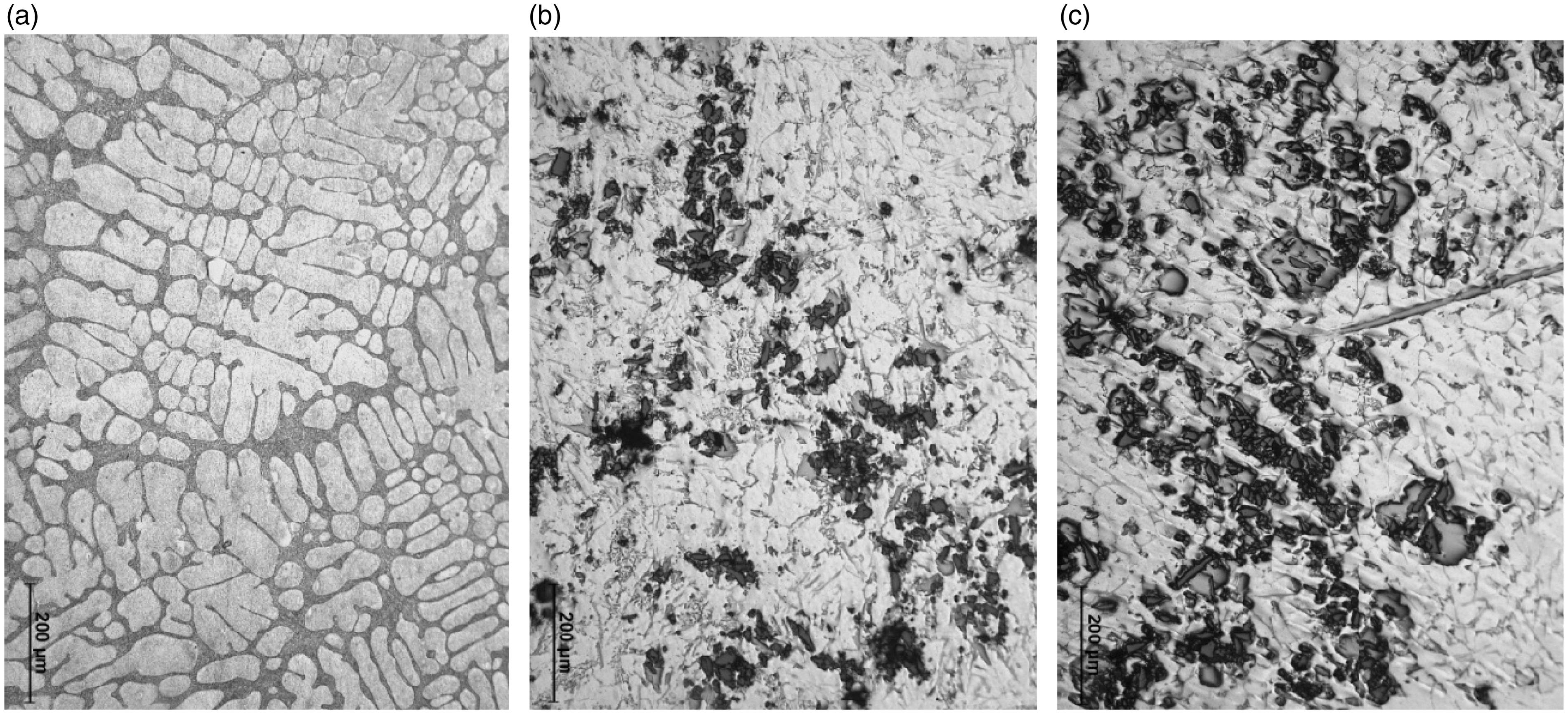
Microstructures of functionally graded A356-10 wt. % SiCp, A356-20 wt. % SiCp ex situ composites and alloy for comparative study produced by vertical centrifugal ring castings at different locations from outer to inner periphery are depicted in Figure 4(a) to (c). Figure 4(a) shows the optical microstructure of as-cast A356 centrifugal ring, which reveals only the presence of primary aluminium and eutectic silicon phase. The size of the primary aluminium and eutectic silicon phases were finer towards the outer periphery than in the inner region due to the higher solidification rate, as a result of high temperature in the preheated mould walls is evident from the structural morphology. The inner region of the centrifugally cast alloy ring is enriched with coarser aluminium and eutectic phases. The structural morphology reveals the size of the eutectic and primary aluminium phases increases from outer to inner periphery. An average dendritic arm spacing of centrifugal as-cast A356 alloy is 29, 31, 38 and 41 µm (outer to inner periphery – Figure 4(a)) respectively. Figure 4(b) and (c) shows the optical micrograph of functionally graded as-cast A356-10 wt. % and A356-20 wt. % of SiCp composite rings taken at specific locations from outer to the inner region. The region near the outer periphery shows higher concentration of reinforcement SiCp than the inner particle depleted region due to the movement of high-density (3.2 g/cm3) SiCp to the outer region by the action of centrifugal force, which will positively influence the mechanical properties like hardness, high toughness and wear resistance where the inner region of the casting is constituted mainly with the low-density (2.67 g/cm3) aluminium matrix. The region very close to the outer periphery (0.5–5 mm) shows less particle concentration compared to the adjacent region (10–20 mm), due to chill zone formation because of the heat in the preheated mould. The region beyond the chill zone is enriched with higher concentration of SiCp because of the propagation of particle from inner periphery to the outer periphery where the solidification happens slowly compared to the chill zone. A particle graded region (15–35 mm) is formed between the particle rich region and the particle depleted region. The region closer to the inner periphery (beyond 40 mm from outer periphery) exhibits the presence of porosities due to the settling of the low-density inclusions and agglomerations due to the lack of centrifugal force nearer to the centre of the mould which affects the solidification rate. High volume fraction of SiCp reinforcement and agglomerations can be observed in the microstructure near the outer region (15–35 mm) of A356-20 wt. % of SiCp than in A356-10 wt. % SiCp FGM (Figure 4(b) and (c)). Studies by Vieira et al.
1
and Rajan et al.3,4 have shown that the eutectic phases are finer towards the outer periphery and an increase in the grain size was observed from outer region to the inner region due to the difference in the cooling rates of the material in the mould.
Optical microstructures of functionally graded materials formed from A356 base alloy, A356–10 and 20 wt. % SiC (X1 at 0.5 mm, X2 at 21 mm, X3 at 35 mm and X4 at 49 mm from outer periphery of the centrifugal castings). (a) A356 base alloy, (b) A356–10% SiC, and (c) A356–20% SiC composite.
XRD analysis
Figure 5 shows the XRD analysis of A356 base alloy, A356-10%SiC composite and A356-20%SiC composite. The analysis shows highest intensity peaks for the major element aluminium at a diffracted angle of 2θ at 38.473° and subsequent peaks at 44.740°, 65.133°, 78.233° and 82.434° that are similar to the observation by Bustamante et al.
14
The peaks of SiCp are identified in A365-10% SiC composite and A356-20%SiC composite systems at 35.627°, 41.385° and at 59.991°. An oxide peak found in the analysis of A356-20%SiC corresponds to the aluminium oxide (Al2O3) at an angle of 46.647°. The peaks of Si and Fe are also found that are present in the A356 aluminium alloy. A peak of Mg2Si is observed at 47.434° that is formed during the solutionising heat treatment of the alloy and composite systems.
XRD pattern of A356 base alloy, A356–10%SiC and A356–20%SiC composite.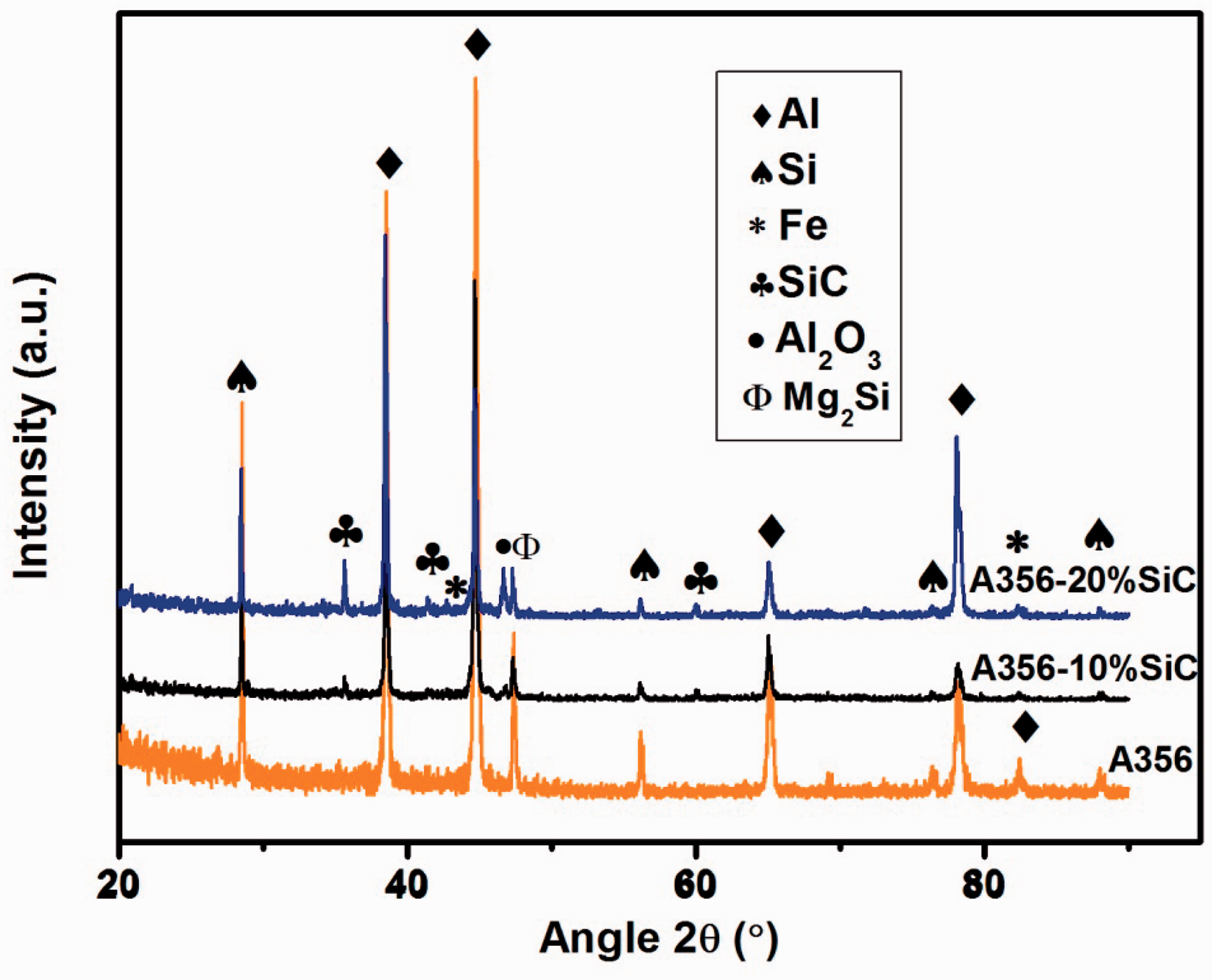
Hardness properties
Hardness of as-casts and precipitated-heat-treated gravity cast Al(356)–SiC composites in BHN.
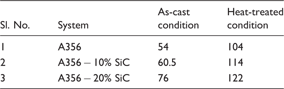
Figure 6(a) to (c) is the graph showing the difference in the hardness profiles of as-cast and heat-treated A356 alloy and functionally graded composites with ex situ reinforcements formed by centrifugal casting technique. The hardness values are more near the outer periphery of the as-cast ring and in the heat-treated samples due to the segregation of high-density SiCp after the chill zone and are confirmed from the graphs. The variation in the hardness profiles from the outer to inner periphery at regular intervals (4 mm) can be clearly observed from Figure 6(a) to (c). Hardness values of heat-treated samples show enhanced results due to the precipitation of phases at the grain boundaries in the solutionising process followed by ageing. The extreme outer end of the ring exhibits only less hardness compared to the nearby regions because of the chill zone formation due to the mould wall temperature. There exists a higher hardness where the region next to the chill zone region and gradual reduction in the hardness values towards the inner periphery of the ring owing to the absence of reinforcement particles at the inner matrix rich region. Figure 6(a) shows the hardness profile of centrifugally cast A356 alloys, which show a maximum hardness of 113 BHN (at 32 mm) and 95 BHN (at 4 mm) in the heat-treated condition. In as-cast condition, the hardness values were 53 BHN (at the chill zone) and an average of 54 BHN at the particle depleted region (at the inner zone) of the ring, which is almost similar to the hardness value of the alloy under gravity cast condition. The hardness values of 10 wt.% SiCp at chill zone for as-cast and heat-treated conditions are 66 and 120 BHN whereas for 20 wt. % SiCp it is 72 and 130 BHN, respectively. Also a minimum hardness at the inner periphery (Figure 6(b)) which is in good agreement with the hardness of the gravity cast alloy samples. The hardness of the 20 wt. % SiCp (Figure 6(c)) reinforced composites, which also show better properties but not much difference in the hardness values when compared with the 10 wt. % SiCp reinforced composites as agglomeration of particles in the composite system and porosities were observed in the inner region. The higher volume percentages of SiCp tend to provide higher hardness values than the matrix region as discussed by Rodríguez-Castro et al.
5
and Velhinho et al.
8
Hardness profile for the as-cast and precipitated-treated samples centrifugal cast. (a) A356 base alloy, (b) A356–10% SiC and (c) A356–20% SiC.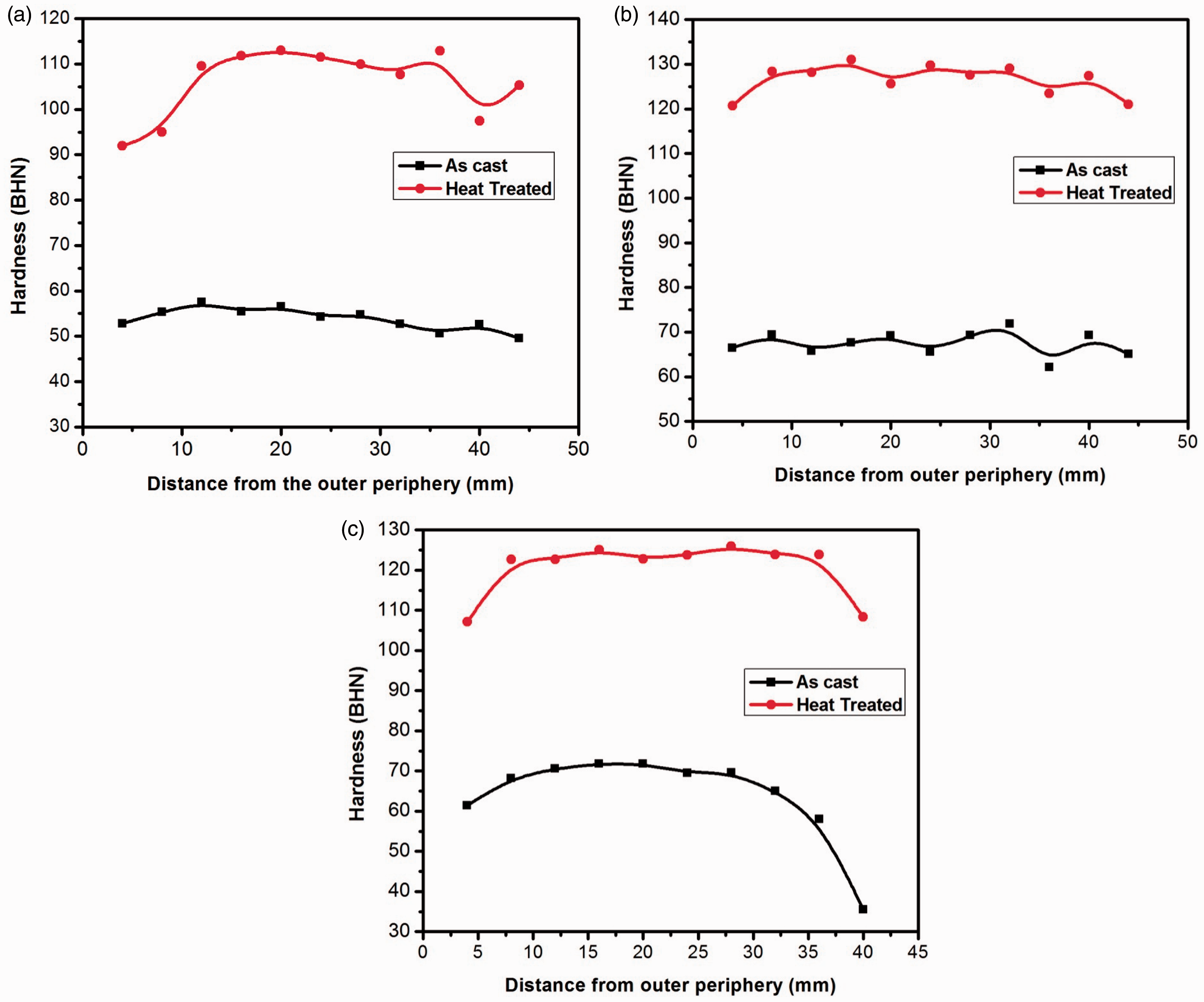
Wear studies
Pin-on-disc wear analysis
As already discussed in “Introduction” section, in order to study the effect of wear rate in different types of wear testing, experiments were carried out both in pin on disc (rotating wear) and in the reciprocating wear test rig (pin on plate), since FGM components also have a prominent role in the automobiles where the actual reciprocation mechanisms undergo. From the hardness values it was observed that heat-treated samples show better hardness magnitude than the as-cast samples. So the wear tests were conducted only for heat-treated samples. Figure 7 illustrates the wear rate values in pin on disc for homogeneous (gravity cast) alloy and composite specimen. The wear studies on the homogeneous specimens reveal a higher rate of wear in the alloy specimen and A356-10 wt. % SiCp reinforced specimen shows higher wear resistance. The alloy specimens had undergone a maximum wear rate of 0.00100 mm3/N m at a load of 117.71 N and a minimum rate of 8.9 × 10⁻⁵ mm3/N m at lower load at 9.81 N. The lower wear rates were observed in Al-20 wt. % SiCp metal matrix composite, which obviously shows because of the existence of higher percentage of SiCp than the 10 wt. % SiCp reinforced metal matrix composite. Figure 8(a) to (c) shows the typical rotating wear behaviour of centrifugally cast 356 alloy and FGM. The wear specimens were taken tangential to the rotating axis from outer and inner portion of the rings in order to maintain the percentage composition of SiCp throughout the specimen. The outer region contains finer grain size of constituent elements whereas the inner region is enriched with coarse grains due to the difference in the solidification rate leading to higher wear rates at higher loads in the alloy system. In the case of FGM, the region near chill zone is enriched with SiCp and the inner region is full of the matrix only, which always shows the wear rate nearer to the base alloy. The graphs of the wear tests (Figure 8(a) to (c)) show enhanced wear resistance properties for outer regions of FGM, due to the presence of SiCp. The mild to severe wear transition occurs at lower load in the case of pure alloy matrix region, whereas it tends to shift towards the higher loads in the case of particle rich region. Wilson and Alpas have also reported that the wear rate of A356 alloy and 20%SiC reinforced aluminium 356 composite shows that the addition of SiC particles in the matrix shifted the mild wear to severe wear regime at higher speeds and loads.
12
Pin-on-disc wear rate values of MMCs produced by gravity casting. Pin-on-disc wear rate values of functionally graded material specimens from outer and inner region. (a) A356 base alloy, (b) A356–10% SiC and (c) A356–20% SiC.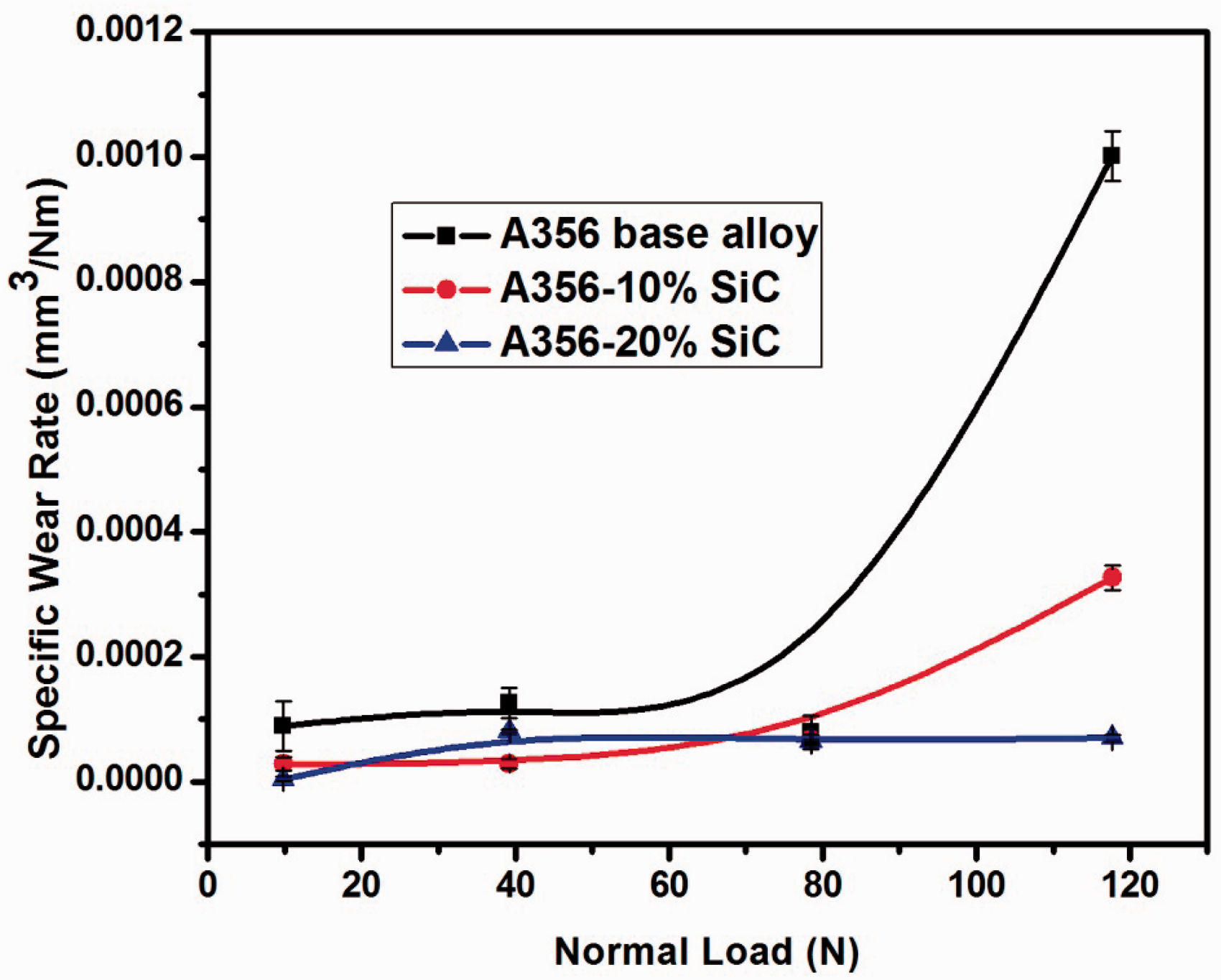
Reciprocating/pin-on-plate wear analysis
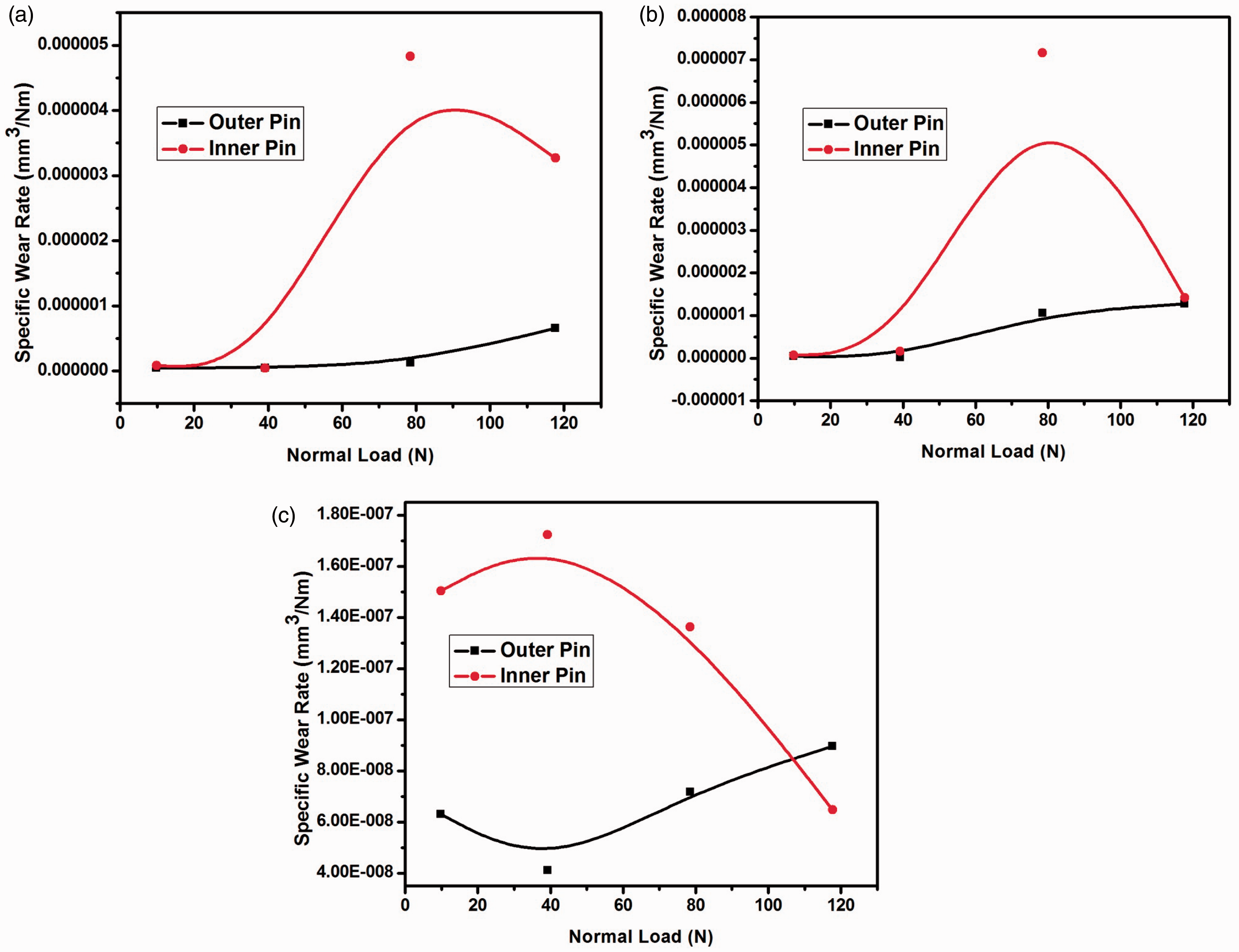
The influence of an increase in load and velocity on wear rate of centrifugal cast alloy ring and functionally graded materials in reciprocating testing condition is given in Figure 9(a) to (c) at velocities of 0.2 and 0.4 m/s and a constant sliding distance of 330 m. It is evident from the graphs that the outer pin specimens of FGM had undergone only a very limited amount of wear when compared to the inner region pin specimens in the reciprocation condition. The wear rate was higher in case of specimens from the inner portions compared to outer region, which almost shows similar wear rate of alloy in the gravity cast condition. This is due to the fact that the inner specimen portion is enriched only with the alloy matrix of coarse grains due to the segregation of less density elements and because of the varying rate of solidification. From Figure 9(a) to (c) it is clear that the volume loss of the FGM decreases with an increase in load and velocity in all the cases. Reciprocating wear studies of 15% SiCp reinforced A319, A336 and A390 aluminium matrix composites carried out by Rajeev et al. have shown that the wear rate decreases with increase in reciprocating velocity up to a particular velocity limit.
17
Reciprocating wear rate values of outer and inner pin specimens of functionally graded materials. (a) A356 base alloy, (b) A356–10% SiC and (c) A356–20% SiC at velocities 0.2 and 0.4 m/s.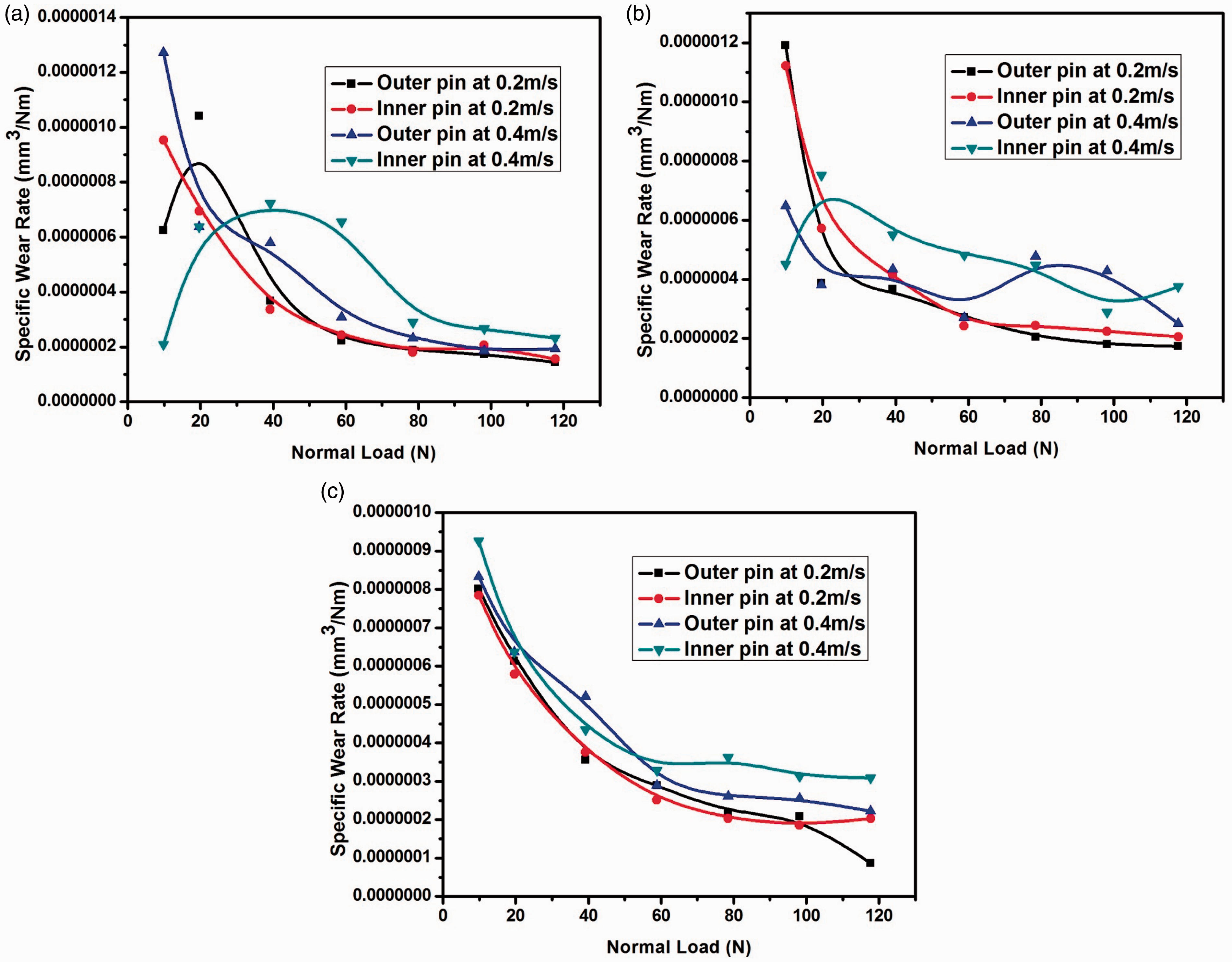
Worn surface analysis
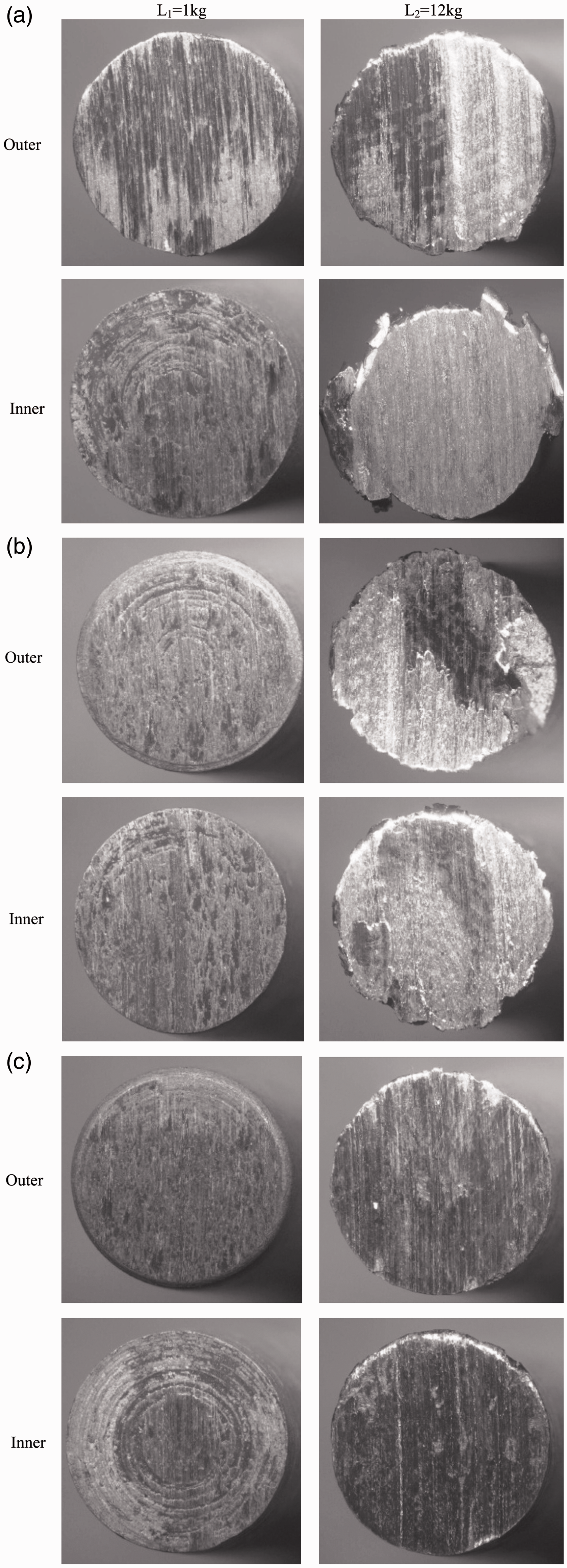
Worn surface analysis of the wear tested pins (gravity cast-A356, A356-10 wt. % SiCp, A356-20 wt. % SiCp and centrifugal cast FGM-A356, A356-10 wt. % SiCp, A356-20 wt. % SiCp) tested in pin on disc at lower load and higher loads is characterised by using stereo micrograph and scanning electron microscopy (SEM analysis). Figure 10(a) to (c) shows the stereo micrographs of the worn pin specimens of gravity cast samples at a lower load of 9.81 N and higher load of 117.72 N. The contact surface of the pin specimen on the counter body is not completely worn out at lower load of 9.81 N in the A356 gravity cast sample. But at a higher load of 117.72 N on the same specimen, it had undergone severe adhesive type of wear and the contact area was completely worn out, which is shown in Figure 10(a). Figure 10(b) shows the stereo micrograph of gravity cast A356-10 wt. % SiCp. The graph reveals that at lower load the contact area of the pin on the counter body has good resistances to wear because of the presence of high-density SiCp in it. Also the wear scars are not clear as in the case of alloy at lower load. But at higher load, it can be clearly visible from the area which is rich with matrix, the specimen surface is affected by ploughing action and the SiCp region is not affected by any severe wear mechanisms. At a lower load of 9.81 N the wear rate is very less in A356-20 wt. % SiCp composite specimen (Figure 10(c)), since the content of SiCp is high. The contact area of 6 mm pin which was in touch with the rubbing surface cannot be able to wear even the circles formed while machining. Meanwhile at 117.72 N load, the material had undergone an adhesive and abrasive type wear throughout the surface of the pin specimen with the edges smudged, due to the high volume fraction of SiCp in this system. Figure 11(a) to (c) is the stereo micrograph of worn pin specimens from outer and inner periphery of centrifugal cast base alloy and FGM rings tested under the rotary wear testing condition. In this case at lower load, the outer specimen of alloy ring shows (Figure 11(a)) only fine wear scars than the alloy tested under the gravity conditions due to the presence of fine grain-sized alpha aluminium particles and eutectic silicon near the outer region as a result of faster rate of solidification at the mould walls. Hence wear rates less than the alloys cast under gravity were taking place in the alloy cast under centrifugal force. At higher load, the material experienced adhesive and abrasive type of wear and the rate of loss of material is less due to the fine grains of alpha aluminium in this region. But the inner pins undergone mild and severe wear at lower and higher loads, respectively, where the pin specimen was smudged, which leads to excessive wear at higher loads. Figure 11(b) and (c) illustrates the stereo micrographs of FGM (outer and inner pins) at lower and higher loads. The outer pins of A356-20 wt. % SiCp display good results against wear, which contains high volume fraction of reinforced SiCp. In certain systems of composites and FGM, the formation of mechanically mixed layers (MML) and oxide layer cannot be neglected, which can be easily identifiable with the stereo micrographs. Aluminium oxide, iron, iron oxide and intermetallic compounds of Al–Fe and Al–Fe–O formed during the sliding operation in the wear test also helped in the formation of MML between the rubbing surfaces of the pin material and the counter surface. MML sometimes acts as a barrier for the protection of the pin material from severe wear conditions. MML cannot act as barriers for every service condition such as at lower sliding speeds and higher loads or at higher sliding speeds and lower load situations. The formations of MML and oxide layers are good resistance to the materials under lower loads, but the wearing and formation of MML are a continuous process which ultimately results in increase or decrease of wear rate when the temperature of counter surface and pin material increases or decreases while in rubbing and the excessive pressure acting on the pin material at higher loads. Earlier studies have reported that the MML and oxide layer formation in the specimens are relatively in good agreement with the microstructures and the hardness of the respective material system.20–23 Rajaram et al. observed that the oxide debris are deposited in these grooves and forms a wear resistant layer.
20
The mechanism of the formation of MML during sliding contact was described in detail by John et al.
21
The thickness and morphology of the MML depended strongly on alloy composition and its properties.
22
Rosenberger et al. have observed that the MML is formed with matrix material, worn reinforcing particles and about 20% Fe coming from the counterface.
23
Stereo micrographs of the worn pin surface-gravity cast. (a) A356 base alloy, (b) A356–10% SiC, (c) A356–20% SiC (L1 at 1 kg load and L2 at 12 kg load). Stereo micrographs of worn outer and inner pin surface-centrifugal cast. (a) A356 base alloy, (b) A356–10% SiC and (c) A356–20% SiC.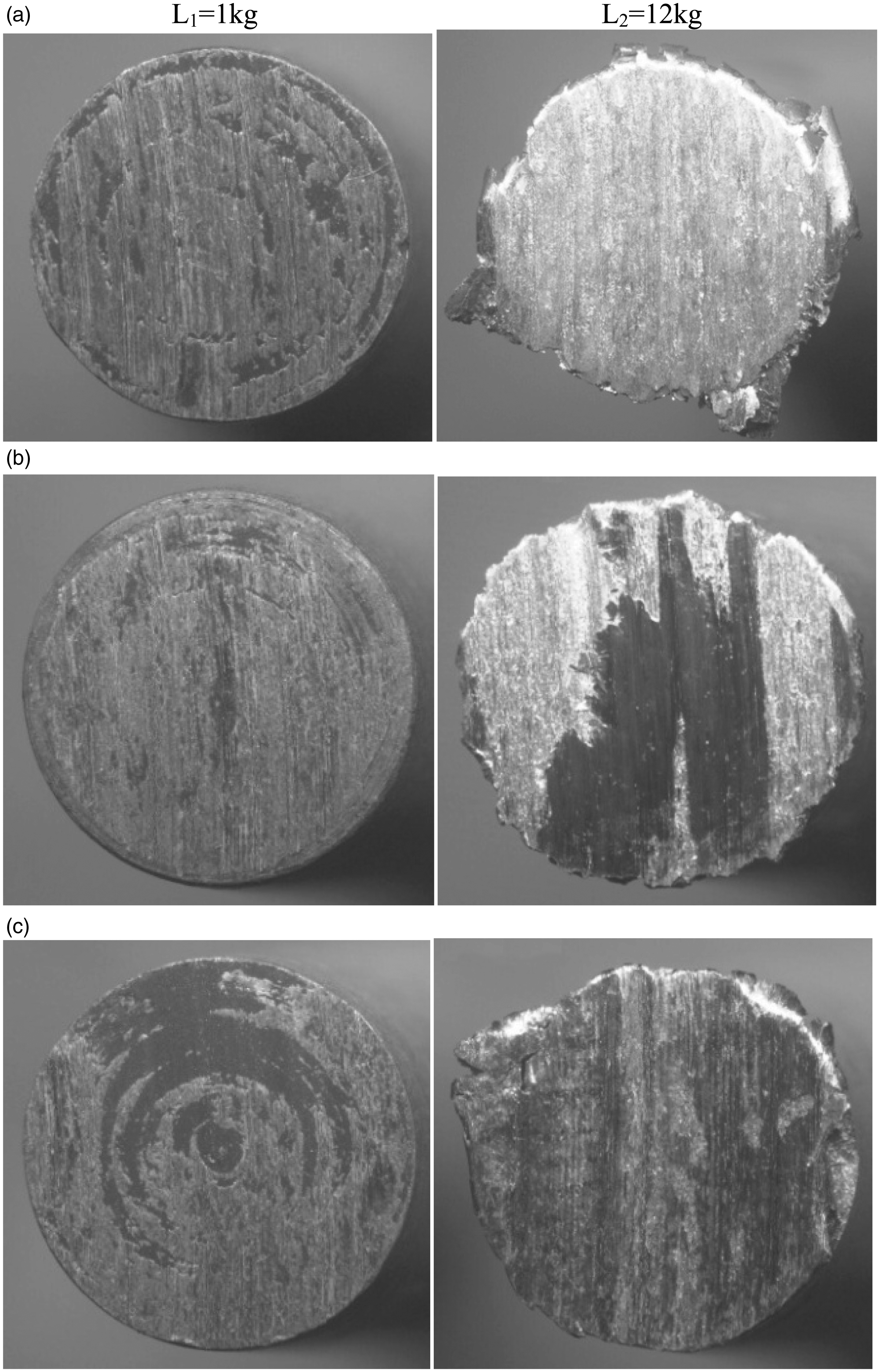
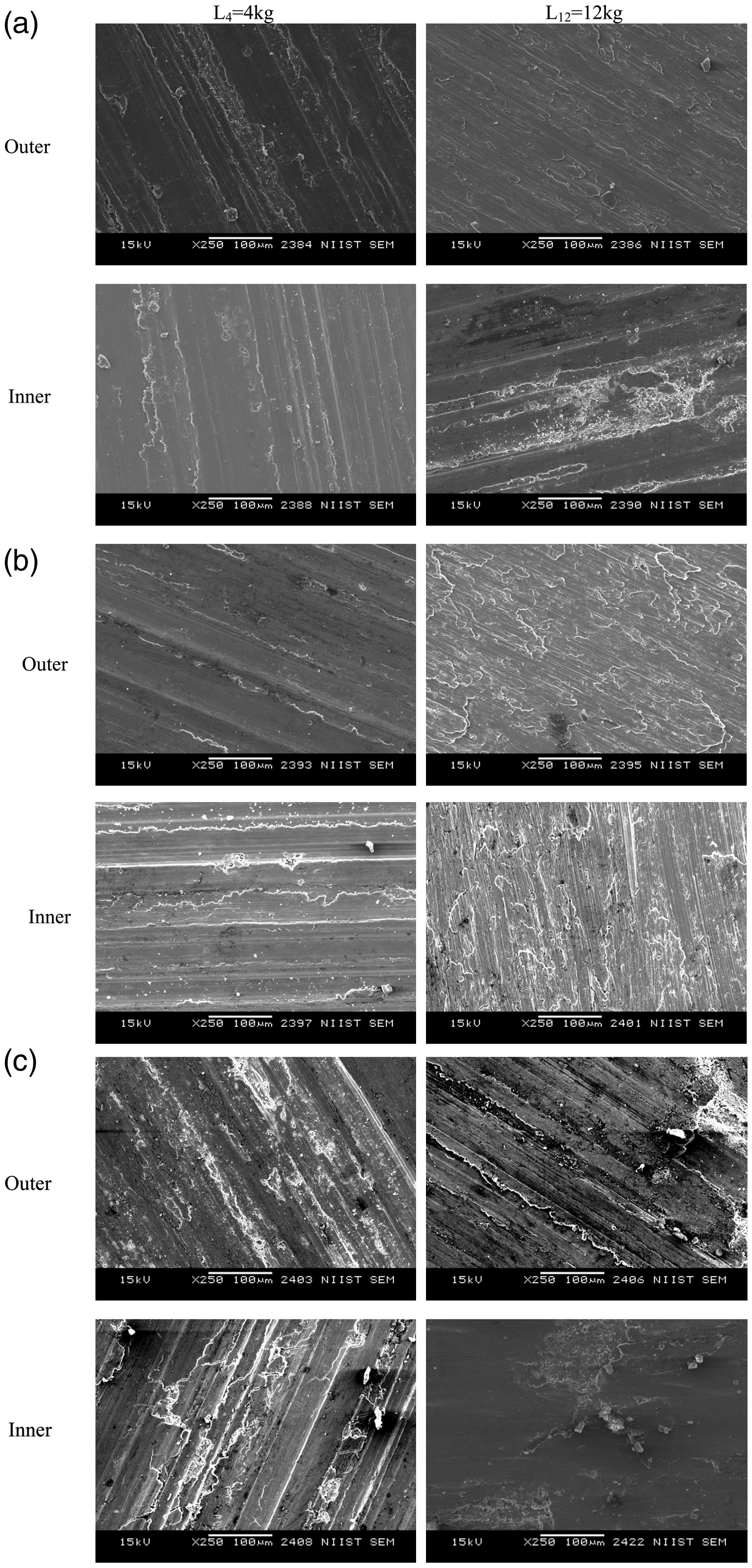
SEM analysis carried out on the worn out pin surfaces of the A356 base alloy, A356-10 wt. % SiCp and A356-20 wt.% SiCp by gravity as well as centrifugal casting tested at 39.24 and 117.72 N loads is depicted in Figure 12(a) to (c) and 13(a) to (c), respectively. The worn out pin surfaces show a distinct pattern of grooves and projections which gives out typical characteristics of wear behaviour at different loads and velocity conditions. The deep penetration in the worn out surface of the pin may be due to the presence of high asperity peaks present in the counter surface and/or particles separated during the sliding action get trapped between the counter body and the specimen material in the test duration. The contact surface of the pin specimen shows fine scars at a lower load of 39.24 N in the A356 gravity cast sample (Figure 12(a)) where at a higher load of 117.72 N on the same specimen, it had undergone severe adhesive type of wear and the contact area was completely worn out that again confirms the result obtained from the stereo analysis. Figure 12(b) shows the SEM image of gravity cast A356-10 wt. % SiCp. At lower load the presence of high-density SiCp provides excellent resistances to wear. The wear scars are not clear at lower load, but at the higher load the matrix region is affected by ploughing. During sliding hard SiC particles protect the material from any further severe wear. At a lower load of 9.81 N Figure 12(c) shows the wear rate of Al356-20 wt.% SiCp and the rate of wear is very less compared to the base alloy system and A356-10 wt.% SiCp composite specimen, due to the higher concentration of SiCp. Figure 13(a) to (c) shows the SEM analysis of worn pin specimens from outer and the inner periphery of centrifugal cast A356 alloy and FGM composite rings tested under the rotary wear testing condition. Figure 13(a) reveals that the outer specimen of alloy ring shows only very subtle wear scars than the base alloy tested under the gravity conditions due to the presence of fine grain-sized alpha aluminium particles and eutectic silicon near the outer periphery as a result of faster solidification when the melts thrown out to the mould walls due to centrifugal force. The material has undergone adhesive and abrasive type of wear at higher loads and the wear rate is less compared to rates at lower loads due to the presence of fine grains of alpha aluminium. Mild and severe wear at lower and higher loads are observed in inner pin specimens (Figure 13(a) to (c)) that lead to tremendous wear at higher loads. SEM images of outer pin specimen show better wear resistant properties at a lower load of 39.24 N and at a higher load of 117.72 N in the 20 wt. % SiC composite system. In general, the outer pin specimens of FGM shows only fine scars of wear on the surface and the wear debris are not accumulated. But after the inspection on the wear surface it is clearly visible that the surface undergoes severe adhesive type of wear and which is evident from the different laminar planes on the surface due to plastic deformation at the particular region in the inner matrix region.
SEM images of the worn pin surface-gravity cast. (a) A356 base alloy, (b) A356–10% SiC, (c) A356–20% SiC (L4 at 4 kg load and L12 at 12 kg load). SEM images of worn outer and inner pin surface-centrifugal cast. (a) A356 base alloy, (b) A356–10% SiC and (c) A356–20% SiC (L4 at 4 kg load and L12 at 12 kg load).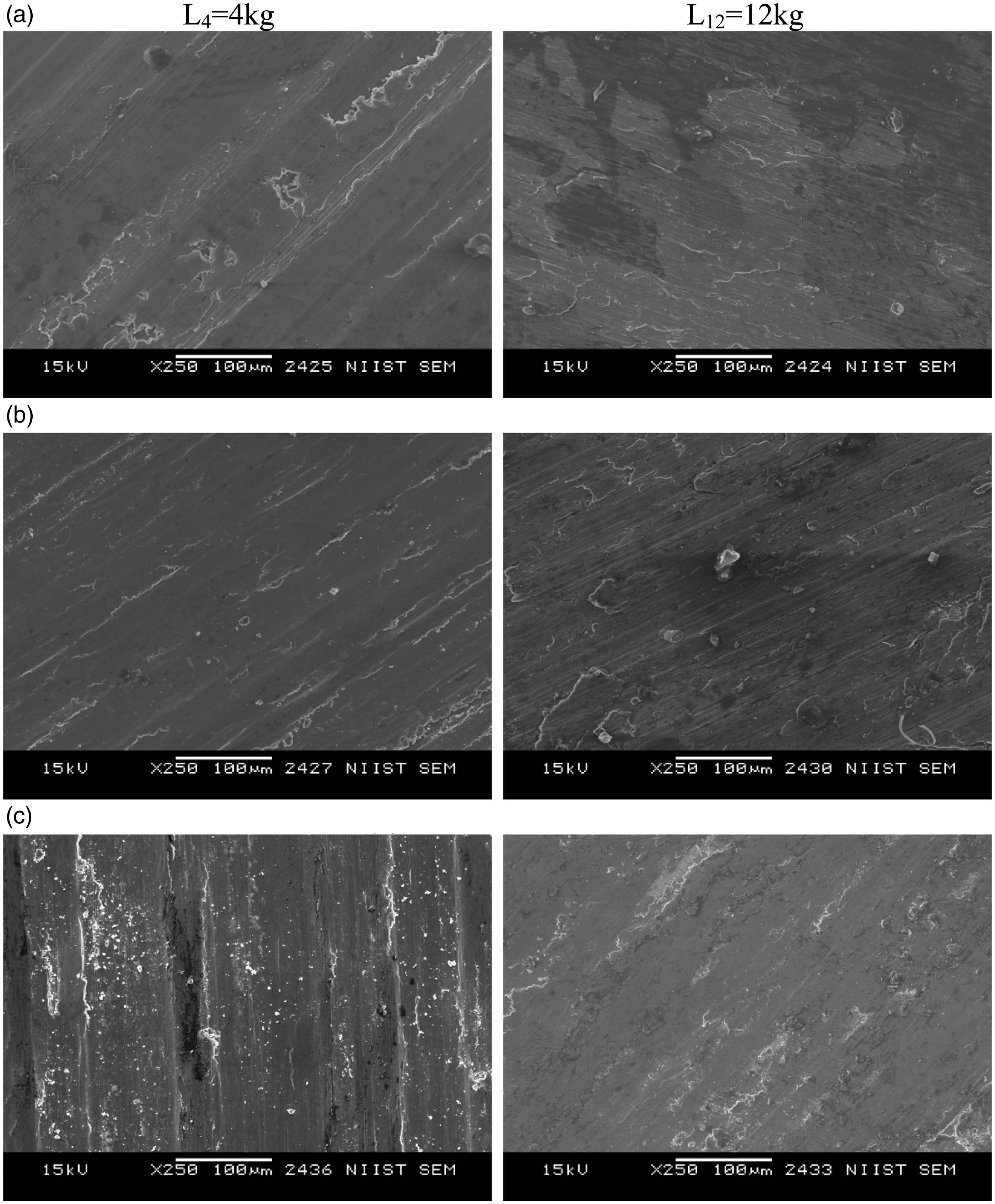
Conclusions
Functionally graded Al–SiCp composite and alloy rings were successfully fabricated using vertical centrifugal casting technique. In alloy ring, the sizes of the primary aluminium and eutectic silicon phases are finer towards the outer periphery due to the higher solidification rate. Functionally graded Al–SiCp composite rings show higher concentration of SiCp towards outer periphery, a gradient transition region and the particle depleted zone are observed. Particle agglomerates formed due to partially wetted particles associated with voids and gas porosities segregate towards the inner periphery. The surface closer to the outer periphery (0.5–5 mm) shows less volume fraction due to the chill zone formation. The Al-20% SiCP FGM ring shows higher hardness of 72 BHN (as cast) and 126 BHN (heat treated) towards the outer periphery. The base alloy shows higher hardness of 57 BHN (as cast) and 110 (heat treated) towards the outer periphery.
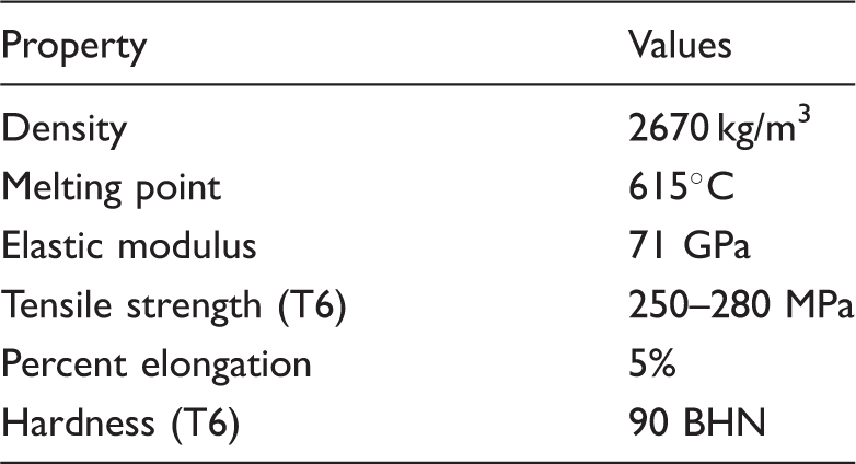
Details of standard properties of 356 Al matrix alloy.
Footnotes
Acknowledgements
The authors are very much grateful to the Director, NIIST and members of Materials Science and Technology Division (MSTD), CSIR-NIIST, Thiruvananthapuram, Kerala and Dr. B. Anil, Former Director, Centre for Engineering Research and Development and members of College of Engineering-Trivandrum, Thiruvananthapuram.
Conflict of interest
The author(s) declared no potential conflicts of interest with respect to the research, authorship, and/or publication of this article.
Funding
The author(s) disclosed receipt of the following financial support for the research, authorship, and/or publication of this article:
We are thankful to CSIR for the project (ESC-0101) funding.