
Abstract
This paper presents the experimental and the analytical results of pultruded glass fiber reinforced polymer sheet pile panels subjected to flexural loading. Full scale four-point flexural tests were conducted up to failure on five sets of joined pairs of glass fiber reinforced polymer Z-pile panels by placing them flat-wise. The influences of transverse and longitudinal fiber volume fraction, span-to-depth ratio and steel plate on the carrying capacity and deformability were discussed. The test results displayed that increasing the fibre transverse and longitudinal volume fraction was helpful for tearing control at the flange-web junction on the compressive side, thus obviously enhancing the load capacity and the flexural rigidity of fiber reinforced polymer sheet pile panels. The additional steel plate improved the rigidity of fiber reinforced polymer sheet pile panels, but the load capacity increased insignificantly due to the debonding of steel and glass fiber reinforced polymer interface. The span-to-depth ratio has little influence on the ultimate load due to the local failure but large deformation occurred in the long-span specimen. Based on classical laminate theory for anisotropic materials, a new equation was proposed to calculate the flexural and shear rigidities of glass fiber reinforced polymer sheet pile panels with corrugated section, in addition to applying classical Timoshenko beam theory. The theoretical results agree well with those obtained from the experiments.
Introduction
Fibre reinforced polymer(FRP) composites have found increased use in waterfront and marine structures due to their advantageous properties, such as light weight, high tensile strength and lower rates of aqueous corrosion.1–3 Among the applications, pultruded FRP sheet piles have been successfully used to construct retaining walls for waterfront/marine structures. Considering the life-cycle cost, the most widely used FRP composites in sheet pile structures are glass fiber reinforced polymer (GFRP) composites. However, the design of GFRP sheet piles is often governed by deflection limit states because of the relatively low elastic modulus in comparison to steel sheet piles. Therefore, it is necessary to enhance the flexural rigidity of GFRP sheet piles through proper design, i.e. increasing moment of inertia of FRP over steel.
Several researchers have investigated the behavior of all-FRP or hybrid-FRP sheet piles under different loading conditions. Giroux and Shao 4 conducted three- and four-point flexural tests on GFRP sheet pile panels with different span-to-depth ratios and extended the Timoshenko’s theory to determine both the flexural and shear rigidities. Linzell and Boothby 5 investigated GFRP unsymmetrical sheet piles subject to a uniformly distributed load. Their modes of failure were dominated by longitudinal joint separation and tearing. Shao and Shanmugan 6 studied the moment capacities, deflection limits and failure mechanisms of single, connected and concrete-backfilled GFRP sheet pile panels. They found that single-panel FRP pile capacity was 15% higher than that of three panels connected together. Additionally, the concrete backfilled hybrid panels exhibited significantly higher moment capacity. Honickman and Fam 7 proposed a trapezoidal hat-shaped GFRP section, which was filled with concrete. Experiments were conducted to investigate the effects of bond systems, voided and solid concrete cores. Moreover, Shao and Shanmugan 8 examined the deflection creep of pultruded composite sheet piling under three-point flexure over 1 year. The predicted 30 year viscoelastic tensile and shear moduli, based on Findley’s model and Timoshenko beam theory, were reduced, respectively, to 68% and 36% of the initial values. Boscato et al. 9 studied the dynamic response of a pultruded FRP sheet pile of 9 m length and concluded that the FRP unit could be installed by using the same pile driving rig and procedure as in steel sheet piling. Besides, the structural performances of wood plastic composite and vinyl sheet piles were studied by Alvarez-Valencia et al. 10 and Dutta and Vaidya. 11 Shao and Kouadio 12 investigated the durability of GFRP sheet piles in water at ambient temperature. The results indicated that the percent absorption at saturation was about 1.72% for the flange and 3.11% for the web. The tensile strength decreased initially with the increase in the percent water absorption and finally stabilized at the state of saturation, whereas no noticeable change was observed in the tensile modulus during the entire water-aging period. 12
Due to the inherent orthotropic behavior of material, the failure mechanism of pultruded GFRP profiles is different from that of metallic sections under the same loading conditions. The pultruded GFRP shapes tend to fail in interlaminar shear under compression loading because of the reduced material properties in the transverse direction.13,14 Moreover, web-flange junction failure was observed for GFRP square hollow sections (SHS) under both end-two-flange and interior-two flange loading conditions. 15 In order to avoid undesirable failure at the web-flange junction of pultruded GFRP SHS and enhance its bearing capacity, Wu et al. 16 proposed the strengthening methods using CFRP sheet or thin-walled steel channel sections. The bearing capacity was increased by up to 70% for pultruded GFRP SHS strengthened with three layers of CFRP sheets and by up to 4 times for pultruded GFRP SHS strengthened with 2 mm thick steel channel sections. 16 The study of Satasivam et al.17,18 showed that the span-to depth ratio greatly influenced the failure mode of GFRP web-flange sandwich structures under flexural loading. Specimens with span-to depth ratio of 7.6 and 14 showed a typical shear failure, whereas specimens with span-to depth ratio of 24 showed final failure of web-buckling and web-flange separation in the region of dominant compressive stress due to bending. 17
Among the previous studies, there are two methods to calculate the theoretical stiffness of thin-walled composite structures using energy methods and Classical Lamination Theory (CLT). Energy methods, such as Rize-Rayleigh or Galerkin method, were usually used to analyze the mechanical behaviour of arbitrarily shaped thin plates, but the closed form solutions were possible only for a limited set of simple boundary conditions and geometries.19–21 The CLT can be used to analyze FRP laminates to determine gross deflection, buckling load, fundamental natural frequency and associated mode shapes.22–25 It is generally accepted that pultruded FRP composite structures can be simulated as laminated composites with equivalent orthotropic mechanical properties. 26 Giroux and Shao 4 derived the analytical solutions for flexural rigidity and shear rigidity of composite sheet piles based on the assumption that the material was isotropic in the plane. Considering the random composite layers, Young’s modulus was expressed as equivalent isotropic elastic constants. 27
Recently, Creative Pultrusions (CP), Inc and US-NSF I/UCRC Center for Integration of Composites into Infrastructure (CICI) of West Virginia University 28 conducted lateral flexural tests on four interlocked series 1580 sheet piles. The panels were 5.49 m long and embedded in compacted gravel at the depth of 1.83 m. Buckling failure was observed at the anchorage. Moreover, full section three-point flexural testing of SuperLoc 1610 sheet pile panels was conducted to experimentally determine the load carrying capacity and flexural modulus. These tests were conducted at various support spans and with the profile in both a positive flexural mode (connection flange intension) and a negative flexural mode (connection flange in compression).
This paper focuses on the flexural behaviour of FRP sheet pile panels consisting of multi-layer E-glass (unidirectional fiber roving, woven fabric and continuous strand mat) bonded with polyester. The specimens with different layers were tested to discuss the influence of fibre volume in the transverse versus longitudinal directions. Moreover, a specimen with flange strengthened by steel plates was tested to investigate the improvement of rigidity. Based on the CLT, the flexural rigidity of FRP sheet pile panels with anisotropic material properties was obtained. Then, Timoshenko Beam Theory (TBT) was applied to calculate the deflections of FRP sheet pile panels under bending. Comparisons of analytical and experimental results in this paper are presented and discussed. Additional, the analytical model was used to calculate the load-deflection curves of SuperLoc 1610 sheet pile panels and compared with the test results of CP.
Experimental program
Specimen for test
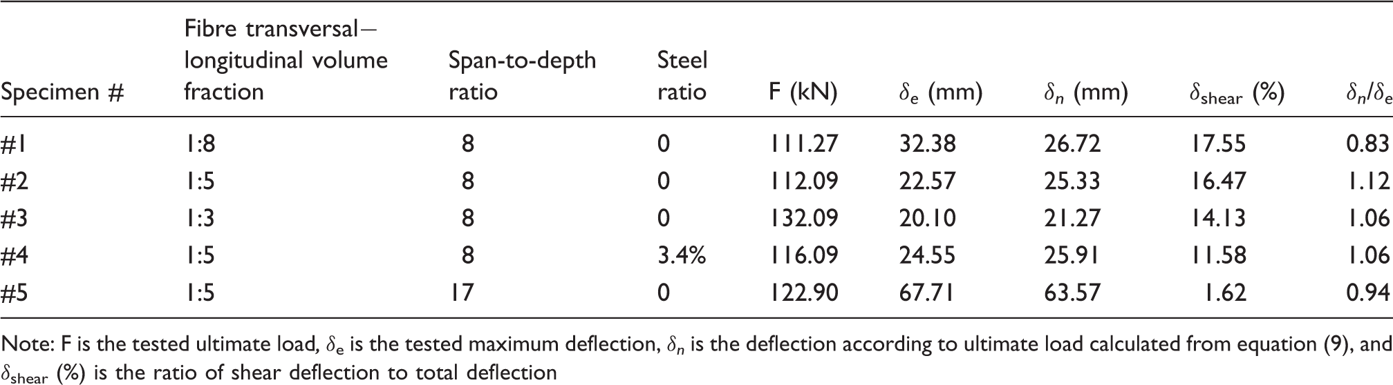
Two sheet pile profiles were tested for this study, a GFRP sheet pile and a steel reinforced GFRP sheet pile. The sections were tested with two Z-sections connected to form a hat section, as shown in Figure 1(a). There were a total of five hat sections tested to study the influences of fibre transversal−longitudinal volume fraction, span-to-depth ratio and steel plate on flexural behaviour of GFRP sheet pile panels. Table 1 provides test matrix summary. Specimens #1, #2 and #3 have different fibre volume fractions in transverse versus longitudinal directions. Specimen 4 was reinforced with four steel plates with a dimension of 50 × 5 mm. The span-to-depth ratio of Specimen 5 was different with other specimens.
Cross section of GFRP sheet piles (units: mm): (a) Hat section, (b) Z-shape sheet pile (Specimens #1, #2, #3 and #5) and (c) Z-shape sheet pile reinforced with steel plates (Specimen #4). Summary of test matrix and results. Note: F is the tested ultimate load, δe is the tested maximum deflection, δn is the deflection according to ultimate load calculated from equation (9), and δshear (%) is the ratio of shear deflection to total deflection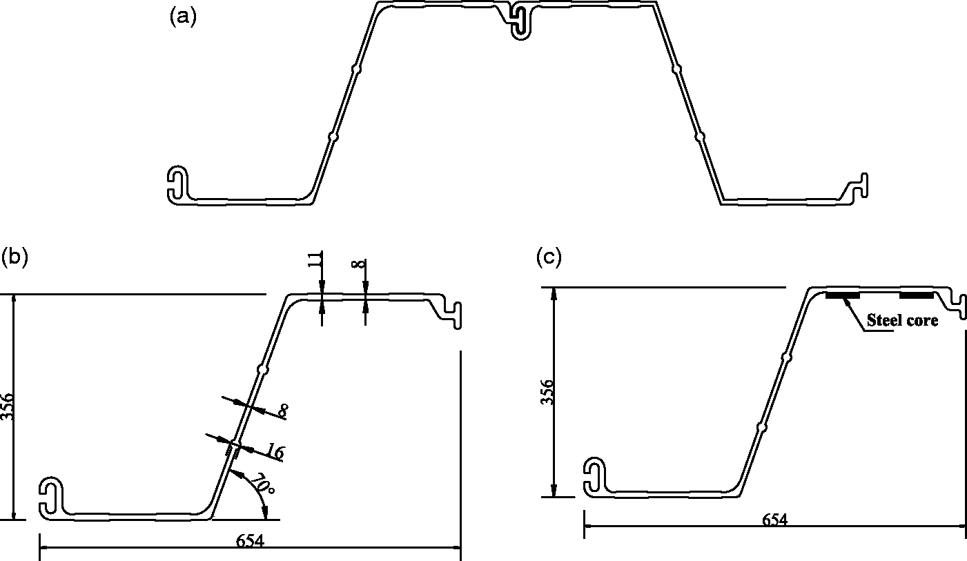
The sheet piles were fabricated at Advanced Structural Composites Center of Nanjing Tech University, China. The pultruded composite sheet pile panels were fabricated using E-glass rovings in the longitudinal direction as inner portion for flexural resistance and bidirectional woven fabrics for transverse strength. Moreover, continuous strand glass mats were used as the outer layer of sheet pile panels. The resin used was an isophthalic polyester resin (Synolite 0593-I-3) supplied by DSM China. The Z-shape section was 356 mm deep and 654 mm wide from the C-T edges, with a general wall thickness of 8 mm, having two circular ridges along the web and two rectangular ridges along the flanges, as shown in Figure 1(b). In addition, in order to enhance the local stiffness of FRP sheet pile and avoid multiple buckling modes on the top flange which were observed by Alvarez-Valencia et al., 10 two Z- shape sheet piles were externally reinforced by steel plates, as shown in Figure 1(c). The surfaces of steel plates were wrapped by hand lay-up of GFRP with wall thickness of 3 mm and were bonded to the top flange of sheet pile panels. The steel plates were continuous in the longitudinal direction.
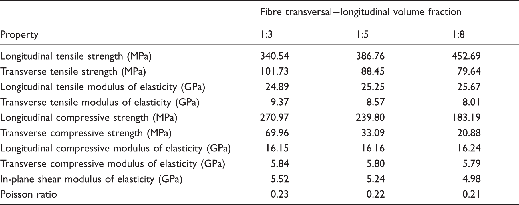
Material properties
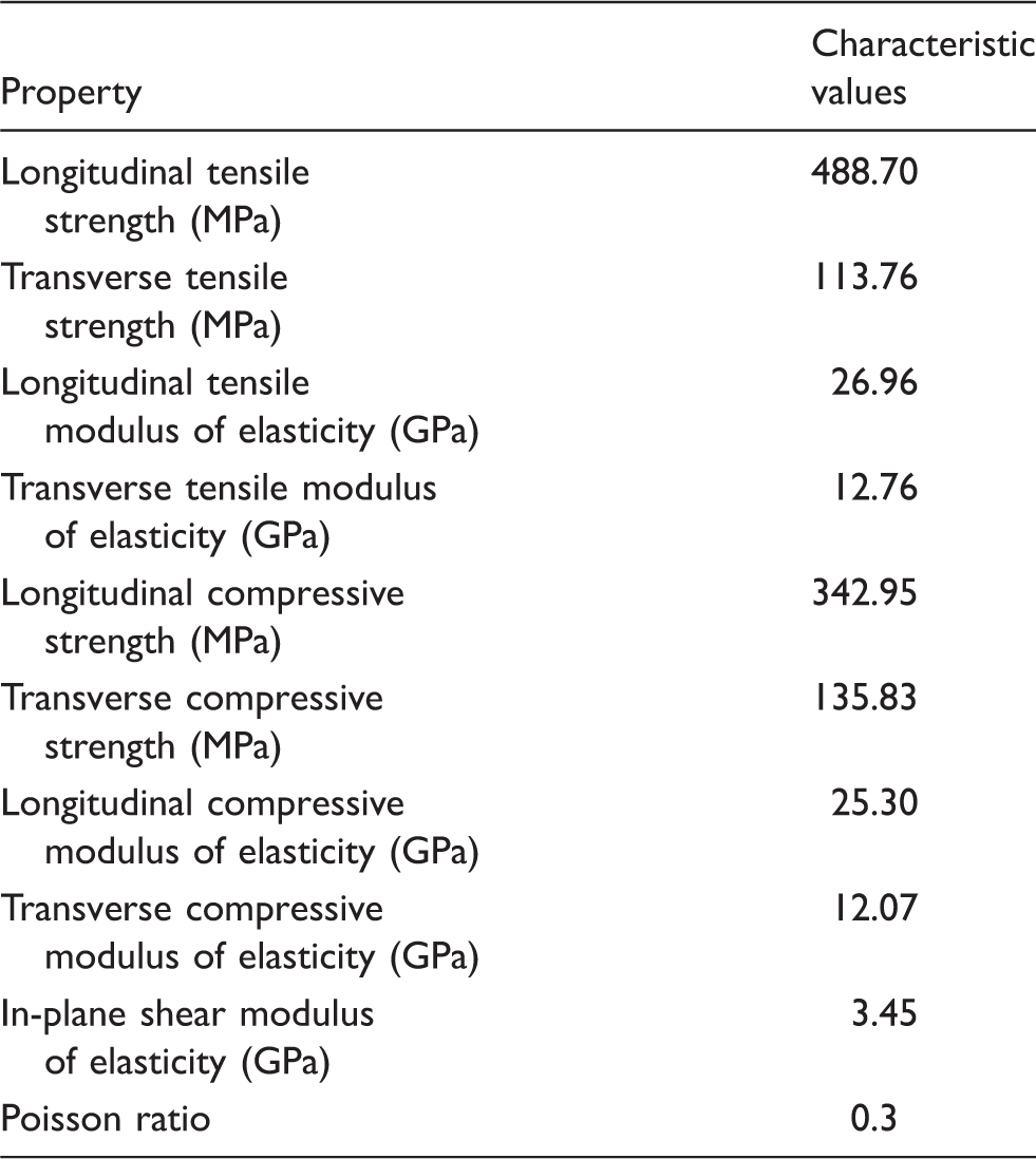
Mechanical properties of tested specimens.
Experimental set-up
The specimens were tested under a four-point bending with load acting at one-third intervals of the span. The experimental set-up consisted of a 500 kN load cell which transferred the load to two load heads using a spreader steel beam. Steel lateral support was used to simulate a typical field environment where the sheet pile sections were attached to adjacent sections. Restraints were provided by the surrounding soil. The lateral supports were designed according to the literature.
32
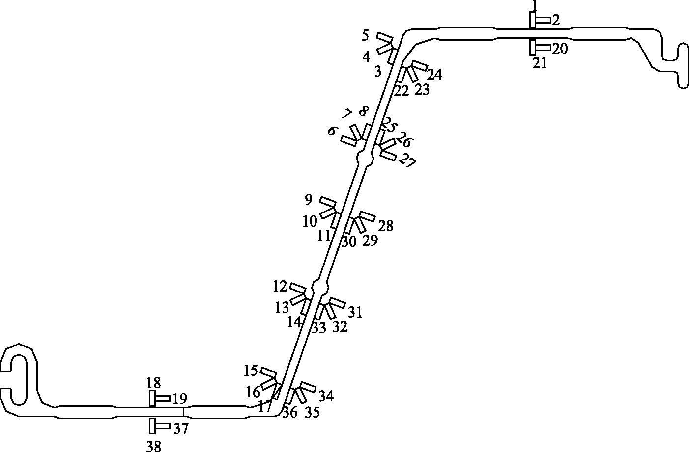
The deflections at mid-span and supports were measured using linear variable displacement transducers (LVDTs). The typical set-up of four-point simply supported pile panel test was shown in Figure 2. In order to monitor the stress state of mid-span cross sections, 38 strain gages (gauge length 10 mm) were bonded to the flange and web surfaces of the test pile panels, as shown in Figure 3.
Four-point bending sheet pile test set-up. Strain gage arrangement on mid-span cross-section.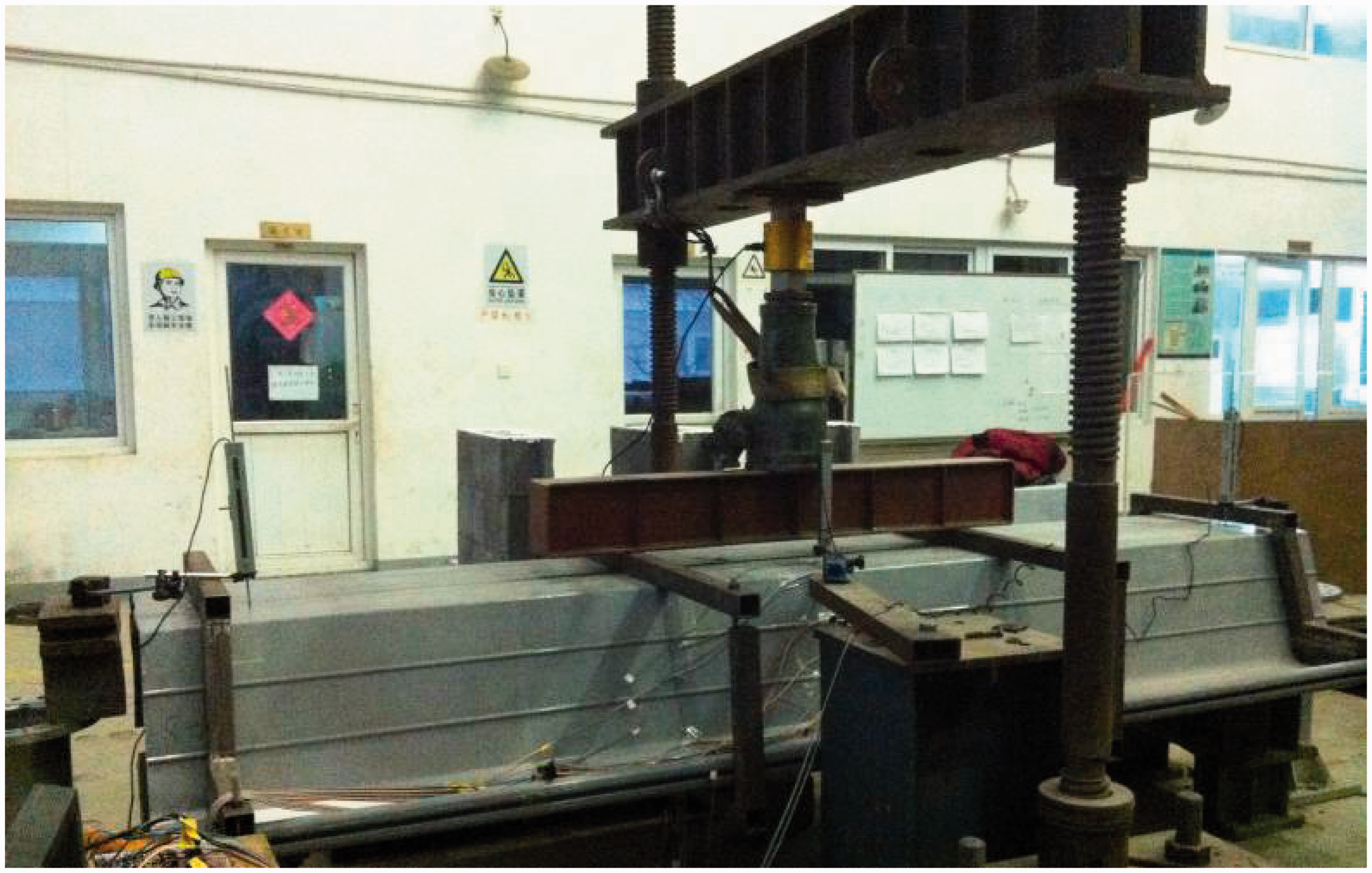
A load interval within one tenth of the estimated failure load capacity was taken and was maintained until the gauge readings became stable while testing. All the specimens were tested to a point where the loading could not be increased any more.
Experimental results
Failure modes
For FRP sheet pile panels with span-to-depth ratio of 8, four common failure modes were observed in specimens #1, #2 and #3, described as (a) crushing of fibers at the loading point, (b) longitudinal cracking through flanges and webs in the mid-span, (c) tearing at the junction of compressive flange and web, and (d) joint failure, as shown in Figure 4. Tearing mode of failure was initiated at the section end and propagated towards the mid-span. The failure was progressed from the interior matrix cracks to interface failure between the layers of woven fabrics and rovings. However, with the increase in volume fraction of transverse fibres, the extent of damage could be improved. Figure 4(a) to (c) show that increasing the volume fraction of transverse fibres is an effective way to prevent the failure of tearing at the junction of compressive flange and web.
Failure modes of FRP sheet pile panels with span-to-depth ratio of 8: (a) Tearing at the junction of flange and web of Specimen #1, (b) tearing at the junction of flange and web of Specimen #2, (c) tearing at the junction of flange and web of Specimen #3, (d) crushing crack at loading point of Specimen #1, (e) joint failure of Specimen #2 and (f) cracking through flanges and webs of Specimen #3.
For FRP sheet pile panels strengthened with steel plate, the failure was initiated by the interfacial debonding between FRP and steel plate, following FRP rupture on the web and local buckling under load point, as shown in Figure 5.
Failure modes of FRP sheet pile panels with steel core: (a) Debonding of steel core and (b) FRP rupture on the web.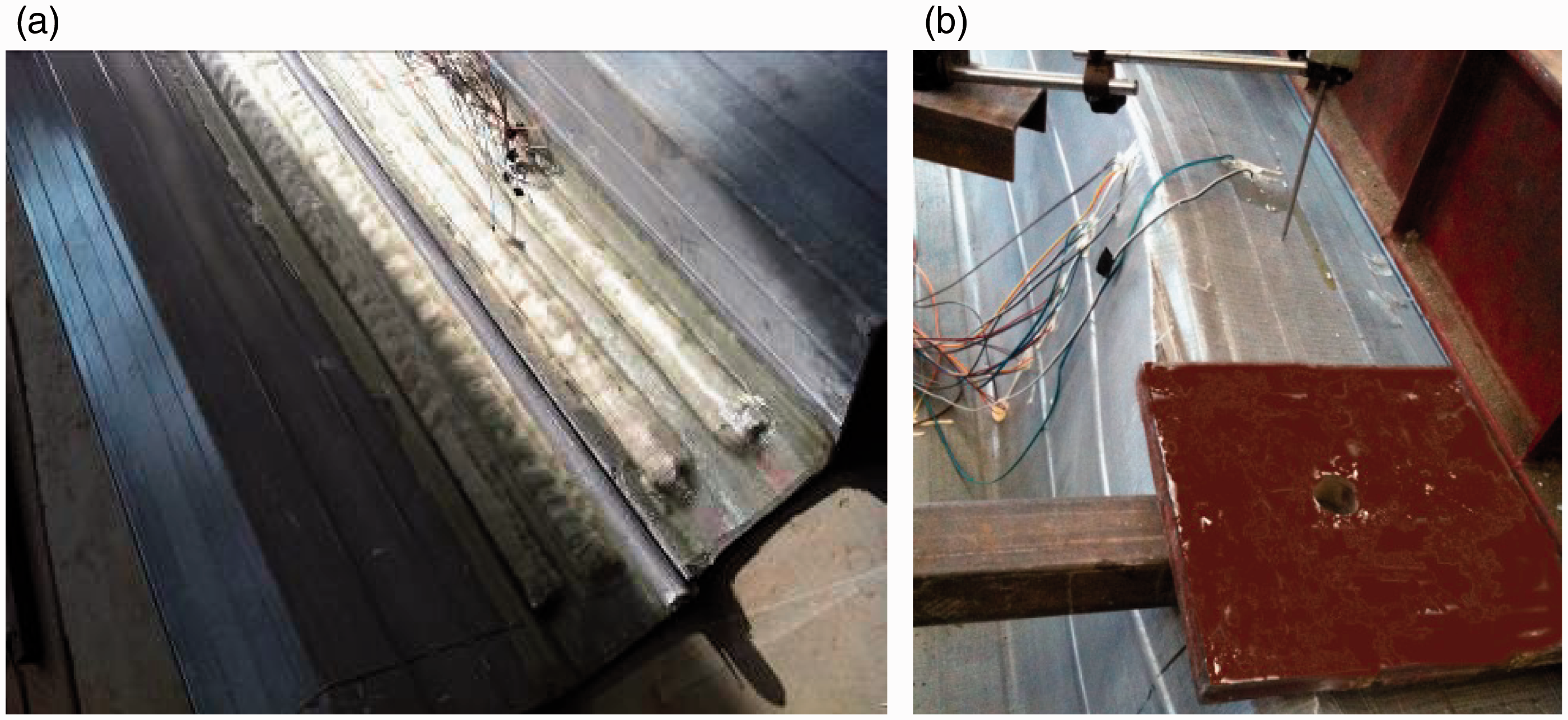
For FRP sheet pile panels with span-to-depth ratio of 17, multiple buckling modes were observed. Due to the longer span between two loading points, the flange surfaces had a wavy pattern in the vertical direction. As the load increased, top flanges at mid-span moved up relative to the loading points leading to web buckling, as shown in Figure 6. Similarly, rupture at the flange-web joint also appeared as well as longitudinal cracking through flanges and webs in the mid-span region. Moreover, large deflection occurred before abrupt failure due to the less flexural rigidity.
Failure modes of FRP sheet pile panels with span-to-depth ratio of 17: (a) Local buckling mode on the top flange, (b) local buckling mode on the web, (c) rupture at the flange-web joint and (d) cracking through the web.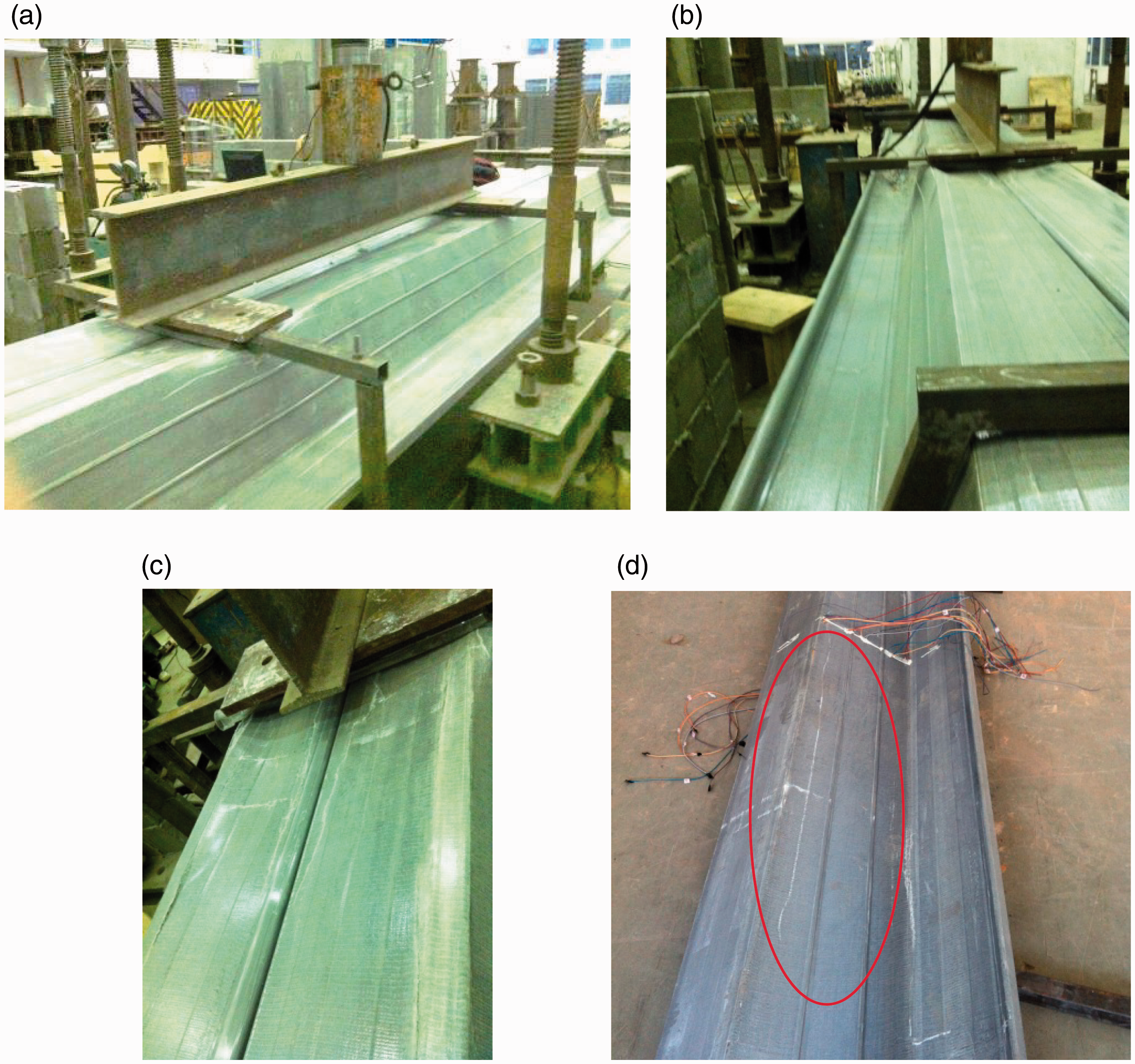
Load-deflection curves
Load versus mid-span deflection measured from the specimens with different fibre transversal−longitudinal volume fractions (i.e. #1, #2 and #3) are plotted in Figure 7(a), where deflections were recorded by the LVDTs. The behaviour of FRP sheet pile panels was predominantly linear-elastic up to about 95% ultimate load. It is obvious that the rigidity of FRP sheet pile panels was accordingly increased as the fibre transversal−longitudinal volume fraction increased. This was attributed to the improvement of delamination at the flange-web joint by increasing the transversal fibre ratio. Very thin woven fabric layers may result in premature failure of the sheet pile panels. According to experimental results, no less than two layers of bi-directional woven fabric (1200 g/m2) on the surface of specimens were necessary to avoid tearing failure mode at the junction of compressive flange. Indeed, the carrying capacities of Specimens #2 and #3 were, respectively, 32% and 12% higher than for Specimen #1, and ultimate deflections decreased by about 14% and 3%. Moreover, the load-deflection response of Specimen # 3 presented a gradually increased structural stiffness with increasing of applied load. Due to the installing errors, the steel lateral supports were not fit the specimen #3 very tightly in the initial loading. With the increase of transverse displacement under flexural loading, the gapping between the steel supports and the specimen were disappeared. Thus, the steel supports can provide full restraints to the specimen resulting in increasing in stiffness of specimen #3.
Load-deflection curves: (a) Specimens with different fibre transversal−longitudinal volume fraction, (b) specimens with different steel ratio and (c) specimens with different span-to-depth ratio.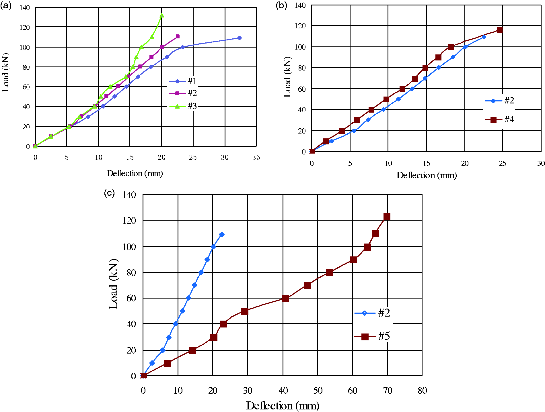
Figure 7(b) compares load versus deflection for different steel ratio (i.e. #2 and #4). The steel ratio is defined as an area ratio of steel plate to FRP sheet pile panels. It shows that the additional steel plate improved the rigidity of FRP sheet pile panels. Due to the fact that the FRP sheet pile panels strengthened with steel plate failed prematurely as a result of debonding at steel – FRP interface, which prevented full flexural capacities, the load carrying capacity of Specimen #4 was similar with that of Specimen #2.
The load versus deflection of our test specimens with different span-to-depth ratio (i.e. #2 and #5) are given in Figure 7(c). For Specimen #5, there was a slip at the joint of C-T edges, when the load increased to 40 kN. For span-to-depth ratio of 17 (compared to 8), the deformation tripled and the slope of the load-deflection curve decreased from 4.85 to 1.55. Furthermore, the tested ultimate load of Specimen #5 was a little higher than that of Specimen #2. This is due to the severe local damage controlled the failure mode of Specimen #2. The dominated failure modes of specimen # 2 included local buckling, tearing at the junction of flange and web, as well as joint failure between two Z-shape pieces. Although buckling failure was also observed in specimen # 5, joint failure between two Z-shape pieces was not obvious in specimen # 5. The capacity of specimen with short span was not fully explored, resulted in the lower ultimate load of Specimen # 2 compared with that of Specimen # 5.
Strain distributions
Figure 8 shows the typical mid-span strain distribution through the depth of FRP sheet pile panels with and without steel plates. For specimen without steel plate, the longitudinal strain distributions remained flat up to ultimate load and the strains increased almost linearly with increasing load, as shown in Figure 8(a). However, the test specimen strengthened with steel plates behaved linearly during the first portion of loading, reaching an applied load of 100 kN, when debonding was observed, as shown in Figure 8(b), and buckled at 116 kN.
Strain distribution curves across the depth at mid-span: (a) Specimen #3 and (b) Specimen #4.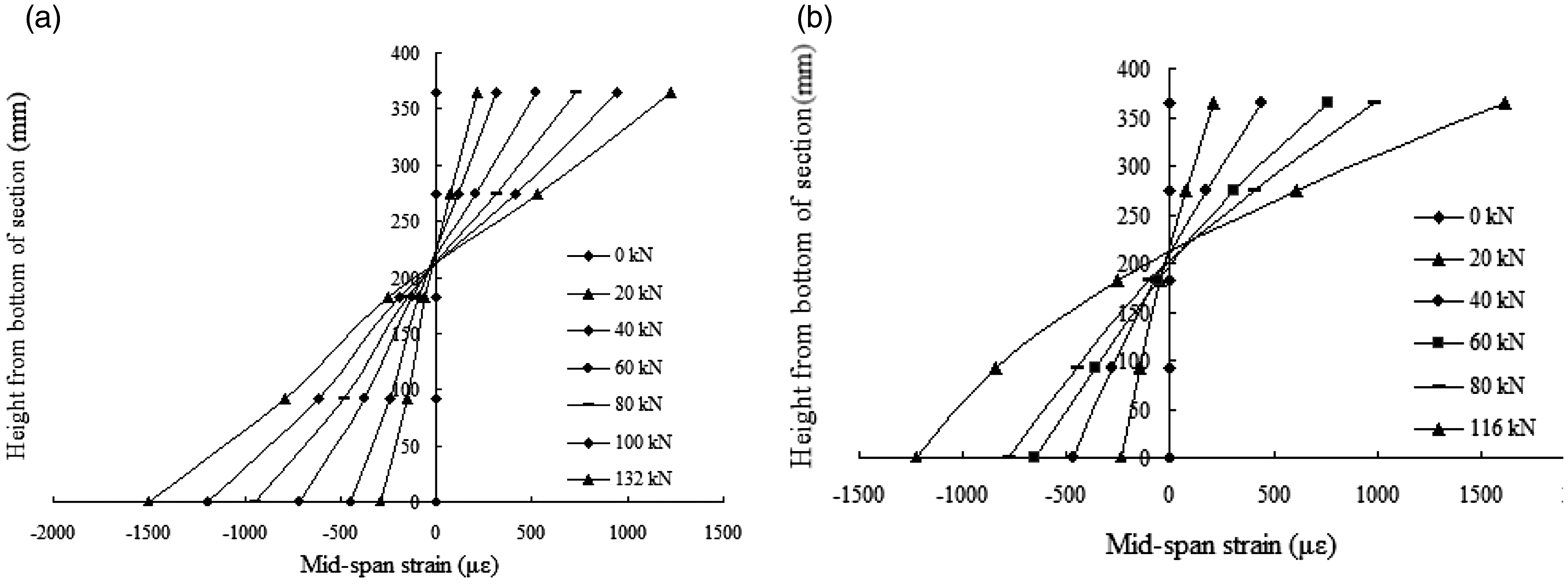
Two typical strain distribution curves across the depth at mid-span for Specimens #1 and #5 are shown in Figure 9. Consistent compressive and tensile strains were developed in the top and bottom flanges. Due to the stress concentration at the junction of flanges and webs, the junction was more prone to failure than others.
Longitudinal strains at mid-span section: (a) Specimen #1 and (b) Specimen #5.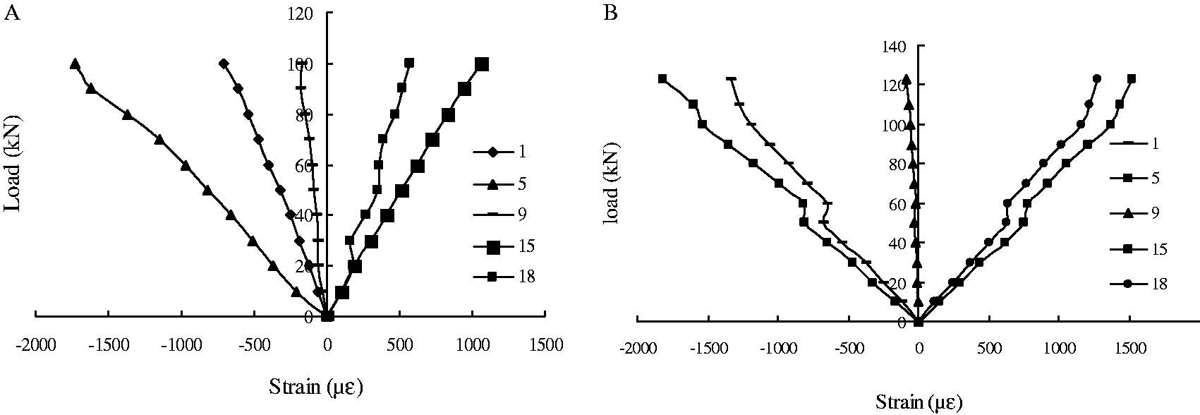
Theoretical approach to determine rigidities
The theoretical flexural and shear rigidities presented herein are based on classical lamination theory (CLT).
33
In deriving the rigidities, the C-T edge effects were neglected, and connection failure was assumed to be absent. The global coordinate system (x–y–z) of the simplified sheet pile cross section is shown in Figure 10. Sheet pile sections manufactured by the pultrusion process are made up of longitudinal fibers, 0°/90° woven fabrics and continuous strand mats arranged in layers. Pultruded section can be assumed to be laminated with different thickness. Moreover, properties of 0°/90° layer were computed by dividing the layer into two laminates of perpendicular fiber orientation angles. It was assumed that each layer has the same thickness.
Global coordinate system of sheet pile cross section.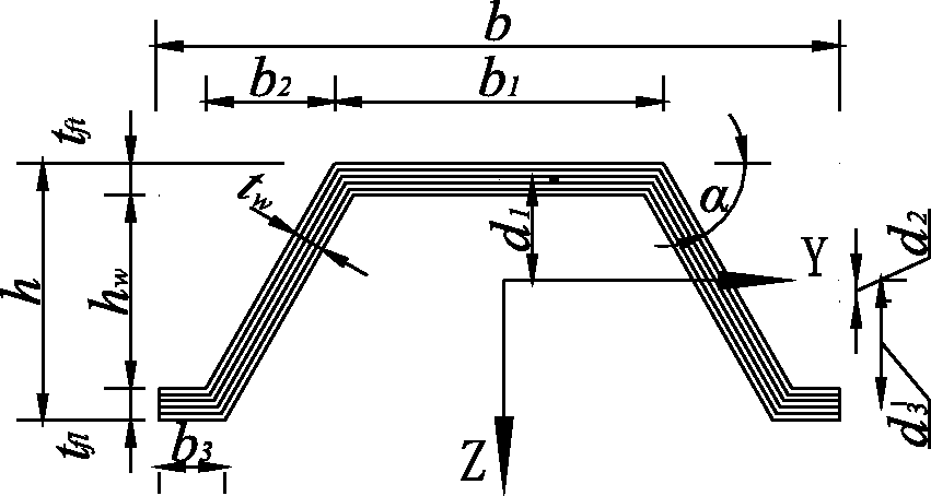
Derivation of local rigidities of flange and web was shown in Appendix 1. Extensional rigidity matrix A and flexural rigidity matrix D for flange and web can be given by
Flange


For symmetric laminates, the flexural-extension coupling rigidity matrix B is zero.
In order to obtain the flexural rigidity of the overall shape, local rigidity terms A and D need to be transformed from the local coordinate system to the global coordinate system by using the parallel axis theorem. Therefore, the flexural rigidity per unit width of the sheet pile panels is given by

Moment of inertia of the overall shape is given by
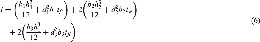
Defining 
Defining 
Displacement function of the sheet pile panels can be obtained based on the Timoshenko beam theory (TBT). The maximum deflection for a four-point loading of a beam of span L and concentrated loads (P) applied at L/3 is given by

Comparison between the theoretical formulas with experimental results
The theoretical formulae proposed herein are employed to simulate the flexural behaviour of tested specimens. Figure 11 shows comparison of analytical and measured load-deflection curves for FRP sheet pile panels. It appears that the straight lines obtained by the theoretical formulae provide good approximation for the curves obtained experimentally. The predicted maximum deflections are compared to the experimental values in Table 1. The mean value of δn/δe is 1.002 with the mean square deviation of 0.104, in which δn is the deflection according to ultimate load calculated from equation (9) and δe is the tested maximum deflection. Results from the proposed formulae are found to be in good agreement with the experimental values.
Comparison of load-deflection curves for: (a) Specimen #1, (b) Specimen #2, (c) Specimen #3, (d) Specimen #4 and (e) Specimen #5.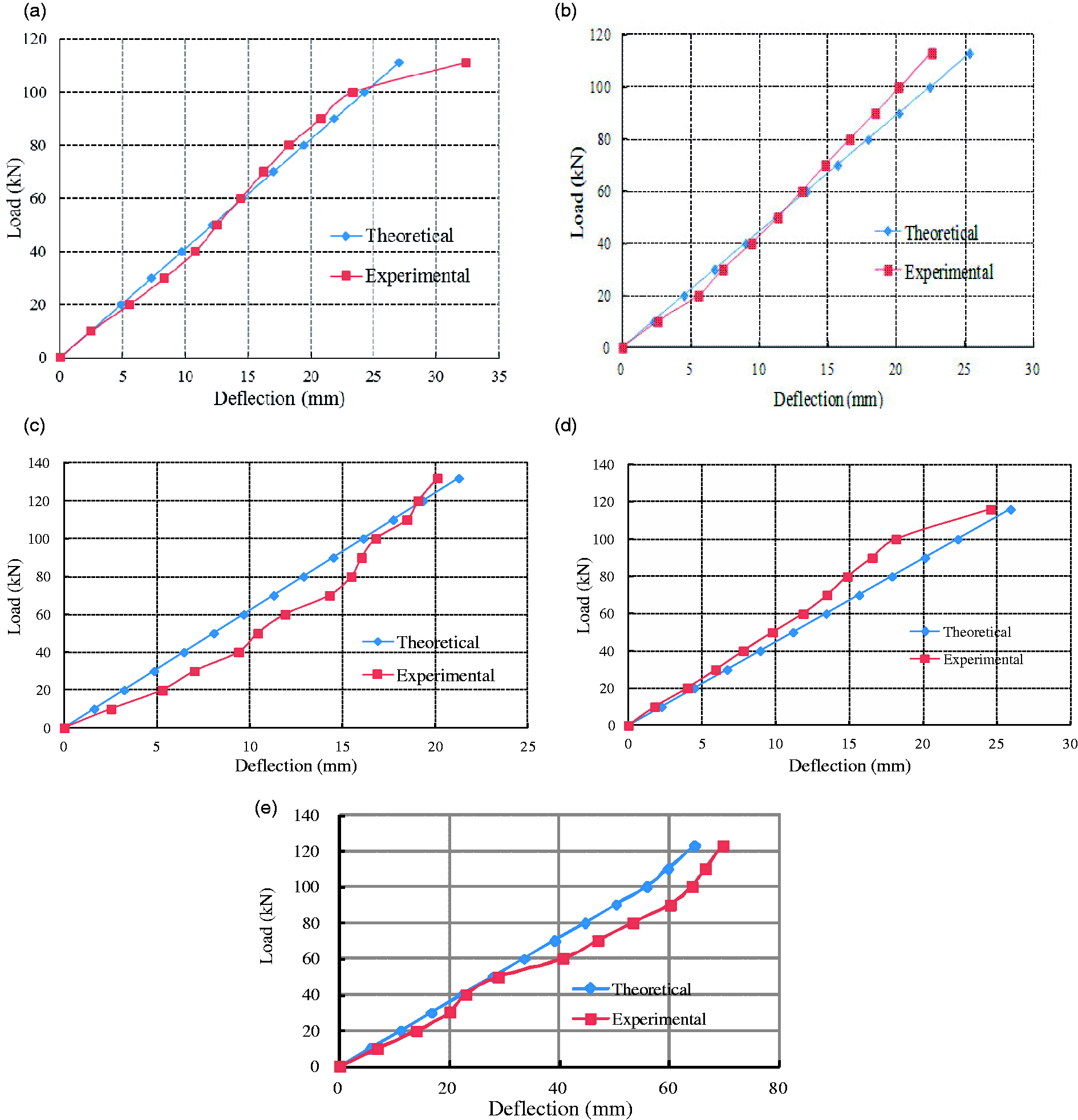
The analytical solutions permit the computation of both the flexural and shear components of deflection. As shown in Table 1, shear deflection accounts for about 12 − 18% of the total deflection for the span-to-depth ratio of 8, and it decreases to about 1.62% for the span-to-depth ratio of 17.
Accuracy of the theoretical model
Mechanical properties of SuperLoc 1610 sheet piles.
Comparison of analytical and measured load-deflection curves for SuperLoc 1610 sheet piles was shown in Figure 12. For specimens with 22.8 and 28.8 span-to-depth ratios, the contribution of shear deflection was neglected. It is evident that the analytical model provides accurate predictions as revealed by the test data. However, the predicted slopes of load-deflection curves for specimens with 22.8 and 28.8 span-to-depth ratios are slightly larger than the test results. This might be due to coupling of flexure and torsion, as it is common in open cross sections of thin-walled composite beams.
35
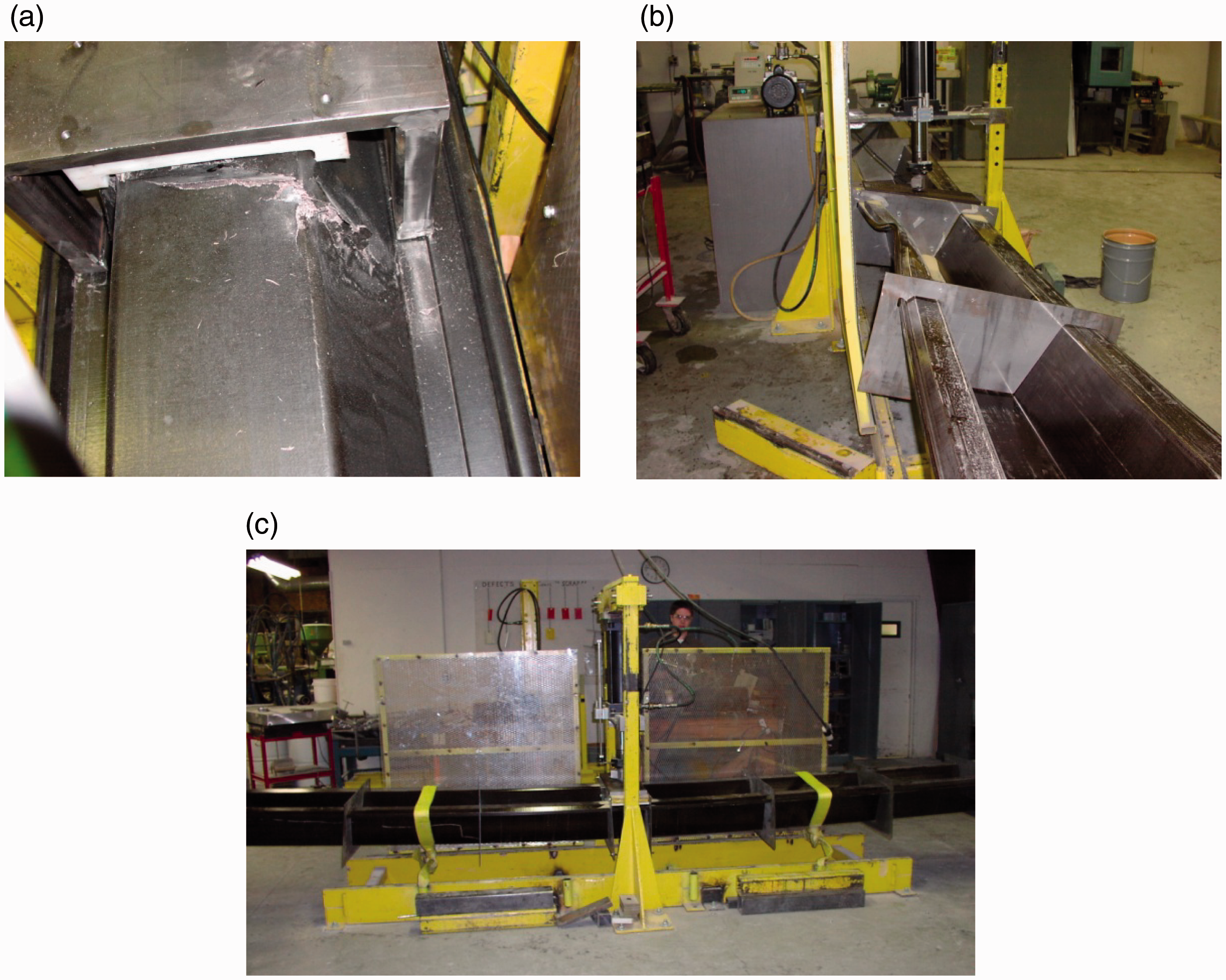
The supports of the sheet piles are not fixed completely to eliminate the influence of torsion, and the long span specimens are especially prone to roll sideways. Failure modes in Figure 13 show that torsional buckling is evident in the long span specimens, while compression failure is observed in short span specimens.
Comparison of load-deflection curves for SuperLoc 1610 sheet piles: (a) L = 3454.4 mm (Positive flexural mode), (b) L = 7415.2 mm (Positive flexural mode), (c) L = 3454.4 mm (Negative flexural mode), (d) L = 5791.2 mm (Negative flexural mode) and (e) L = 7415.2 mm (Negative flexural mode). Failure modes of SuperLoc 1610 sheet piles: (a) Compression at the load application for specimen with 13.6 span-to-depth ratio, (b) Torsional and connection flange buckle for specimen with 22.8 span-to-depth ratio and (c) Torsional buckle for specimen with 28.8 span-to-depth.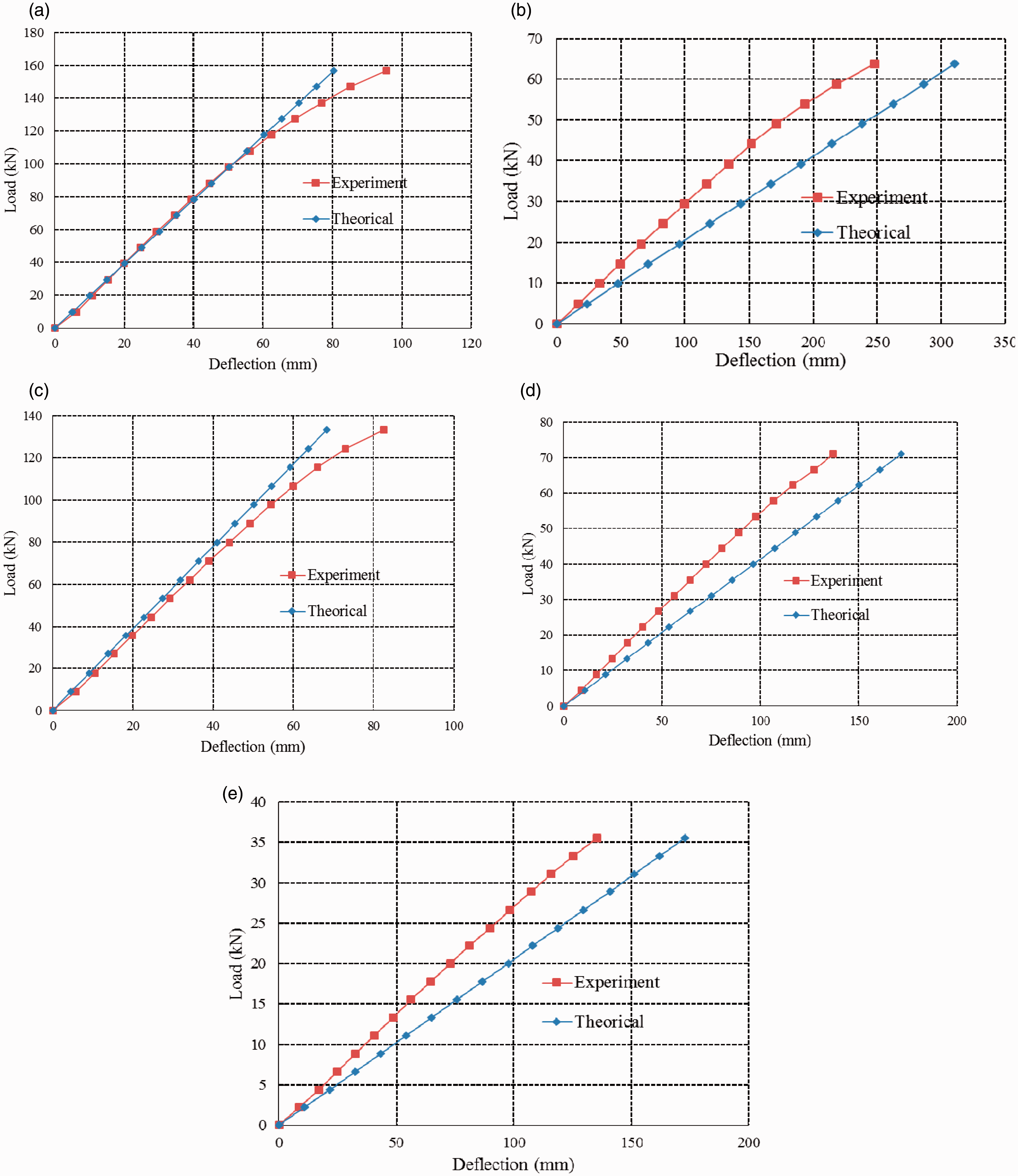
Conclusions and recommendations
Based on analytical and experimental studies conducted herein, following conclusions are obtained:
Fibre volume in transverse versus longitudinal directions not only influences the failure modes of FRP sheet pile panels, but also the rigidity and load capacity. The additional steel plate can improve the rigidity but has little influence on their ultimate carrying capacities due to debonding at steel – FRP interface. Both the flexural and shear rigidities of the FRP sheet pile panels were estimated based on CLT, including maximum deflection computations with TBT under 4-point loading. Comparison of load-deflection curves showed good correlation of TBT data with the experimental data. Increasing the fibre volume in transverse versus longitudinal directions resulted in improving failure load under tearing at the web-flange junction. Moreover, in order to exert the full effect of steel plate, it is necessary to strengthen the end interface of steel plate and FRP. Thus, the carrying capacity of FRP sheet pile panels strengthened with steel plate can be improved obviously.
Footnotes
Declaration of Conflicting Interests
The author(s) declared no potential conflicts of interest with respect to the research, authorship, and/or publication of this article.
Funding
The author(s) disclosed receipt of the following financial support for the research, authorship, and/or publication of this article: The financial supports from National Natural Science Foundation of China (51308288), Key Program of National Natural Science Foundation of China (51238003) and Jiangsu Government Scholarship for Overseas Studies (JS-2013-184) are highly appreciated.