
Abstract
A two-step finite element framework is presented that examines the effect of microscale thermal residual stress on the nanoindentation properties of fibre-reinforced composites. Firstly, micromechanical modelling is used to determine the residual stress state following thermal cooldown of a carbon-fibre composite material from cure temperature. A three-dimensional finite element nanoindentation model is then used to characterise the effects of residual stress on material properties determined by nanoindentation theory. The results show that the hardness of the matrix pockets decreases following thermal cooldown due to the existence of equibiaxial tensile residual stresses. The hardness property is also found to decrease for the majority of interfacial region stress states, while the microstructural areas where the effects of the residual stress are nullified are determined. The indentation modulus property is relatively insensitive to the microstructural residual stress, and thus is the recommended indentation property to be determined when carrying out a comparative parametric analysis between microstructural regions. The property changes are shown to be insensitive to any errors associated with contact area estimation using the Oliver and Pharr method.
Introduction
In recent decades, nanoindentation has become a widely used technique to characterise material behaviour at small scales. Advances in instrumentation and refinements in analysis methods1–3 have seen a large increase in use of the technique across numerous material systems. In recent years the technique has seen increasing use in the characterisation of composite materials and their constituents. 4 This research has been mainly focused on the characterisation of two regions within the microstructure, namely, the matrix constituent regions5–8 and the ‘interphase’ region which lies adjacent to the fibre–matrix interface.9–14 Indentations carried out into the in situ matrix material have shown an apparent increase in hardness5,7 and modulus 8 compared to the material properties in bulk form. Meanwhile the measured properties of the interphase region have been found to be both softer than the matrix constituent in some cases and harder in other cases, depending on the material system being investigated and the adhesion-promoting fibre surface treatments used. 10 While these apparent microstructural property changes have generally been attributed to chemical interactions between constituents and fibre treatments, or altering curing conditions due to the surrounding microstructure,11,14 it has also been proposed that thermal and/or chemical residual stresses could also contribute to the variation of measured properties. 10
Several micromechanical models of fibrous composite materials have shown the significance of the residual stress states generated in the material microstructure following material processing.15,16 These residual stresses develop in the material microstructure as a result of the mismatch in thermal expansion coefficients between the fibre and matrix phases, and vary spatially throughout the microstructure. 17 While the effects of these residual stresses on the mechanical performance of composite materials has been characterised previously,16,18,19 their effect on constituent material properties measured using nanoindentation in fibrous composites has yet to be investigated, and so forms the main topic of investigation herein.
The sensitivity of nanoindentation properties to the magnitude and nature of such residual stresses has previously been successfully investigated through the use nanoindentation experiments and modelling on aerospace aluminium alloys,20,21 steel 22 and thin-film materials.23–27 While the vast majority of these investigations assume an equibiaxial stress state and use an asymmetric modelling approach, Breuils et al. 22 carried out full three-dimensional (3D) finite element simulations, allowing the effects of non-equibiaxial stress states to be determined. In these material systems, the material properties measured using the nanoindentation technique are dependent on the nature and magnitude of the residual stress-state in the substrate, with compressive stresses generally leading to an increase in the calculated properties, and a decrease in properties observed for cases where tensile residual stresses were present. However, the degree to which the constituent material properties of long-fibre reinforced composite materials, measured through nanoindentation, are affected has not yet been investigated. In this paper, a combined micromechanical and contact finite element modelling approach has been used to characterise the effect of microscale residual stresses on the nanoindentation of a fibrous composite microstructure.
Nanoindentation theory
In a conventional nanoindentation test, the displacement of the indenter tip is monitored as a function of the load. A maximum load or displacement is applied to the indenter tip, followed by the unloading back to zero load. The most commonly used indenter tip geometry for nanoindentation experiments is the three-sided pyramid Berkovich indenter. The Oliver and Pharr
1
method is currently the most extensively used method of determining modulus and hardness. Hardness (H) is defined as the load on the indenter tip (P) divided by the projected contact area (A)

The contact stiffness is defined as the initial slope of the unloading curve. This can be related to the reduced elastic modulus of the contact using equation (2)
28


Finite element analysis
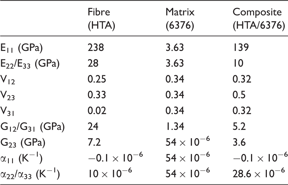
The material under investigation is HTA/6376, a high strength composite material used in the aerospace industry. The material consists of high strength unidirectional carbon fibres (HTA) bound by a toughened epoxy matrix (6376). The resulting composite has a high fibre volume fraction of almost 60% with a mean fibre diameter of 6.6 μm. 30 The commercial finite-element code ABAQUS v6.13-1 was used to create the models and carry out the analyses.
Modelling strategy
An overview of the modelling strategy employed in this investigation is illustrated in Figure 1, which consists of two stages of modelling. Firstly, plane-strain micromechanical modelling was implemented to determine the state of residual stress in the HTA/6376 composite microstructure following thermal cooldown from the cure temperature (448 K) to room temperature (298 K). Additional residual stresses induced due to matrix chemical shrinkage and through the process of specimen planing have not been considered in this analysis.
Finite element modelling strategy.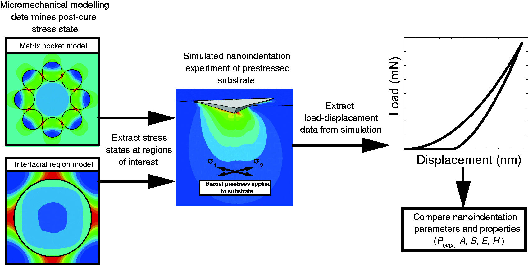
To determine the effect of the microstructural residual stress states on the nanoindentation of the 6376 matrix material, the in-plane stress states at the regions of interest to nanoindentation studies have been extracted from the micromechanical plane-strain models. In order to isolate the effects of these residual stress states, free from any constraint effects associated with fibrous composite indentation,5,8,31,32 these stress states were then applied to a separate 3D substrate material. A finite element simulation of the indentation process was then carried out to predict the indentation response of the pre-stressed 6376 matrix material, as shown in Figure 1. The effect of the residual stress states on the indentation properties is then determined. The models shown in Figure 1 are described in more detail in the following subsections, where the geometries and boundary conditions for each model type are detailed in Figures 2, 3 and 4.
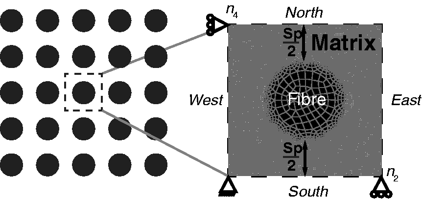
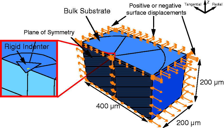
Schematic and mesh of plane-strain thermal cooldown finite element model for a matrix pocket of 15 μm radius. Single-fibre unit cell with periodic boundary conditions and example mesh for inter-fibre spacing (Sp) of 5 μm. Three-dimensional finite element indentation model showing detail of the indentation site and the boundary conditions used to apply an equibiaxial stress state prior to indentation.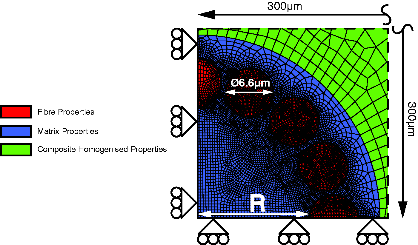
Thermal cooldown models
The two main fibrous composite microstructural regions of interest to nanoindentation studies are the large matrix pockets and the interfacial matrix regions adjacent to the fibre–matrix interface. Separate model geometries have been devised for each of these regions in order to investigate the nature and magnitudes of the residual stresses which exist in these regions in a parametric manner.
Matrix pocket region
Interfacial region
To investigate the nature and magnitude of the residual stress in the interfacial regions post-cure, a single-fibre periodic square unit cell has been used. A schematic of its representative volume element (RVE) is shown in Figure 3. Periodic boundary conditions were applied to the RVE to ensure a macroscopically uniform stress/displacement field existed across the boundaries of the RVE.33,34 These consist of a series of tie constraints which require corresponding nodes on each opposing face of the RVE to undergo identical displacements. The periodic boundary conditions can be expressed in terms of the nodal displacement vector, u, such that


Three-dimensional indentation models
In order to determine the effects of the microstructural residual stress states on nanoindentation data, 3D finite element simulations of the indentation process have been used. The use of full 3D modelling allows the effects of both equibiaxial and non-equibiaxial stress states to be determined. 22 The bulk 6376 epoxy has been modelled as a 400 × 400 × 200 μm 3D deformable solid in order to ensure that far-field boundary effects on the indentation were negligible. A single plane of symmetry has been applied to the mid-plane of the nanoindentation substrate under the point of the Berkovich indentation, as shown in Figure 4. Prior to the indentation step, the substrate geometry was pre-stressed in a separate step through the use of a biaxial combination of tensile or compressive surface displacement boundary conditions on the outer faces of the substrate geometry, as highlighted in Figure 4. The basic constitutive equations of linear elasticity were used in combination with the elastic properties of the 6376 matrix material, in order to determine the biaxial combination of outer surface displacement boundary conditions required to produce the required residual stress state.
The Berkovich indenter tip has been modelled as a 3D discrete rigid solid. The load–displacement data for frictionless indentations was compared with data where the coefficient of friction varied between 0 and 0.9. The hardness and modulus were found to vary by a maximum of 1.3% when comparing the models with friction with the frictionless models for all residual stress cases. Therefore an assumption of frictionless contact was deemed valid, and results from frictionless models are presented herein. After the application of the substrate displacements, the indenter was pushed into the substrate to a maximum depth of 1 μm and then withdrawn back to its original position. This indentation depth was chosen for convenience and the results are representative of an indentation of any depth given that the substrate material is large enough to prevent any boundary effects on the indentation response.
Material behaviour
The matrix and fibre constituents were modelled using the elastic properties in Table 1. The HTA fibres were assumed to exhibit transversely isotropic linear elastic behaviour. The 6376 epoxy resin was assumed to exhibit isotropic linear elastic behaviour while its non-linear plastic behaviour was modelled using the pressure-sensitive Mohr–Coulomb yield criterion. This yield criterion accounts for the hydrostatic pressure sensitivity of the 6376 epoxy resin and has previously been used to predict yielding in polymers associated with fibrous composite materials.15,31,35,36 The Mohr–Coulomb criterion induces yield in the material when the combined normal (σn) and shear (τ) stresses reach a critical level according to the following equation

Results and discussion
Matrix pocket region
Thermal cooldown stresses
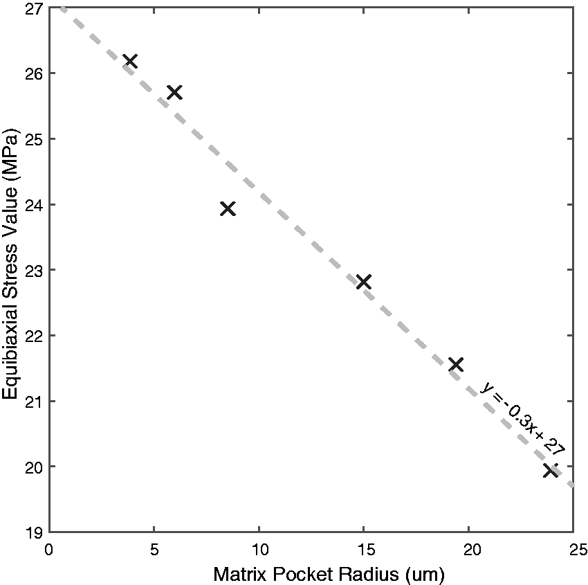
The distributions of the maximum and minimum principal stresses for the 6376 matrix pocket of 5.97 μm radius are shown in Figure 5(a) and (b), respectively. A relatively homogeneous stress state was observed across the vast majority of the matrix pocket except in the regions very close to the fibre matrix interface. The homogeneous region is highlighted by the hatched central regions in Figure 5. The in-plane principal stresses within the homogeneous stress regions were found to be in a state of elastic equibiaxial tension for the full range of matrix pocket sizes investigated. The values of the equibiaxial principal stresses for the pockets are plotted against the size of the matrix pocket in Figure 6. It can be seen that the magnitude of equibiaxial tensile stress decreases almost linearly with increase in matrix pocket size.
(a) Maximum and (b) minimum in-plane principal stress state following thermal cooldown for the 6376 matrix pocket with a radius of 5.97 μm. Equibiaxial stress versus size of matrix pocket.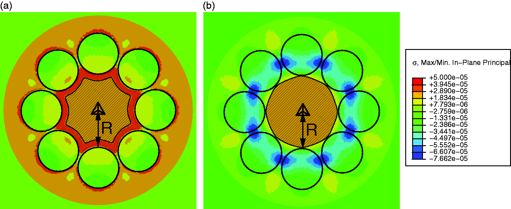
Simulated indentation results
The simulated load–displacement curves for some of the residual stress states in the matrix pocket sizes considered are shown in Figure 7 and compared with the simulated load–displacement curve for the case with no residual stress applied. The residual stress has a noticeable effect on the load–displacement data; most markedly, the load required to reach the constant 1 μm indentation depth reduces with decreasing pocket size due to the larger residual stresses present. The effect of the residual stress states from each pocket size on the nanoindentation parameters (Pmax, A and S) and calculated properties (H and E) is shown in Figure 8, where the values have been normalised against those from the non-prestressed substrate indentation. The hardness (H) property is influenced to a much greater degree than the indentation modulus (E) property, decreasing by up to 11.9% in comparison with the non-prestressed substrate. Another interesting finding is that the value of the in situ hardness changes by only 3.4% across the full range of in situ matrix pocket sizes. This indicates that while the residual stress is clearly an important factor when comparing the response of bulk material with in situ material, the effect is much less substantial when comparing the response of just the in situ pockets across a wide range of sizes.
Load versus displacement data extracted from the finite element simulations for various pocket residual stress states. Normalised indentation parameters plotted versus matrix pocket size.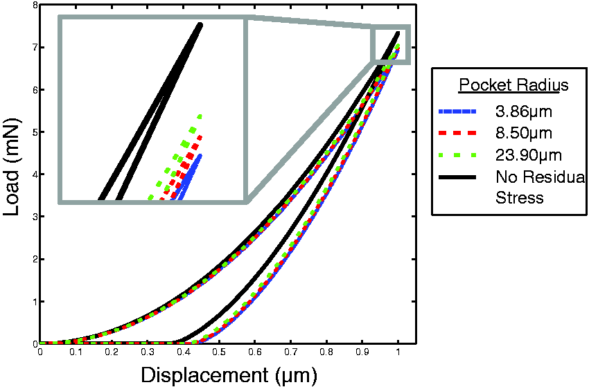
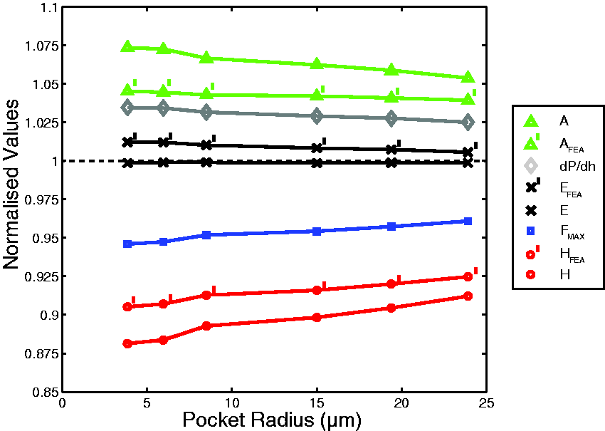
Previous finite element investigations have shown that the presence of residual stress in a substrate can lead to errors when determining the true projected contact area using the Oliver and Pharr methods of analysis due to the effects of material pile-up or excessive sink-in behaviour. 21 For comparison, the true projected contact areas have also been extracted directly from the 3D finite element models and the values of indentation hardness and modulus recalculated using these directly determined areas using equations (1) and (2). These values were then normalised by their respective values from the non-prestressed substrate indentation, and plotted in Figure 8. These projected contact areas are still up to 4.5% greater than those extracted from the stress-free model, resulting in calculated values of hardness which are up to 9.5% smaller than that of the initially stress-free substrate. This indicates that the stress state has a greater influence on the areas calculated using the Oliver and Pharr method, while also having a substantial effect on the actual contact areas extracted directly from the finite element analysis. Thus, the change in the measured properties, plotted in Figure 8, is not solely due to excessive pile-up or excessive sink-in inducing error in the Oliver and Pharr area prediction. The values for the indentation modulus do not deviate by more than 1.2% from that of the stress-free value, and are therefore shown to be insensitive to the equibiaxial tensile stress state which is present in the matrix pockets.
Interfacial region
Thermal cooldown stresses
The residual stresses in the first element of matrix material adjacent to the fibre–matrix interface have been resolved in the radial and tangential directions relative to the centre of the fibre. The variation of both the radial and tangential residual stresses for the case where the inter-fibre spacing was 0.25 μm is shown in Figure 9. The stresses in each direction have been plotted separately on a polar plot. The circumference of the central fibre represents the axis of zero stress, with positive (tensile) stresses protruding out of the fibre and negative (compressive) stresses plotted inside the fibre’s dashed boundary.
The variation of radial and tangential interfacial region stresses for an inter-fibre spacing of 0.25 μm.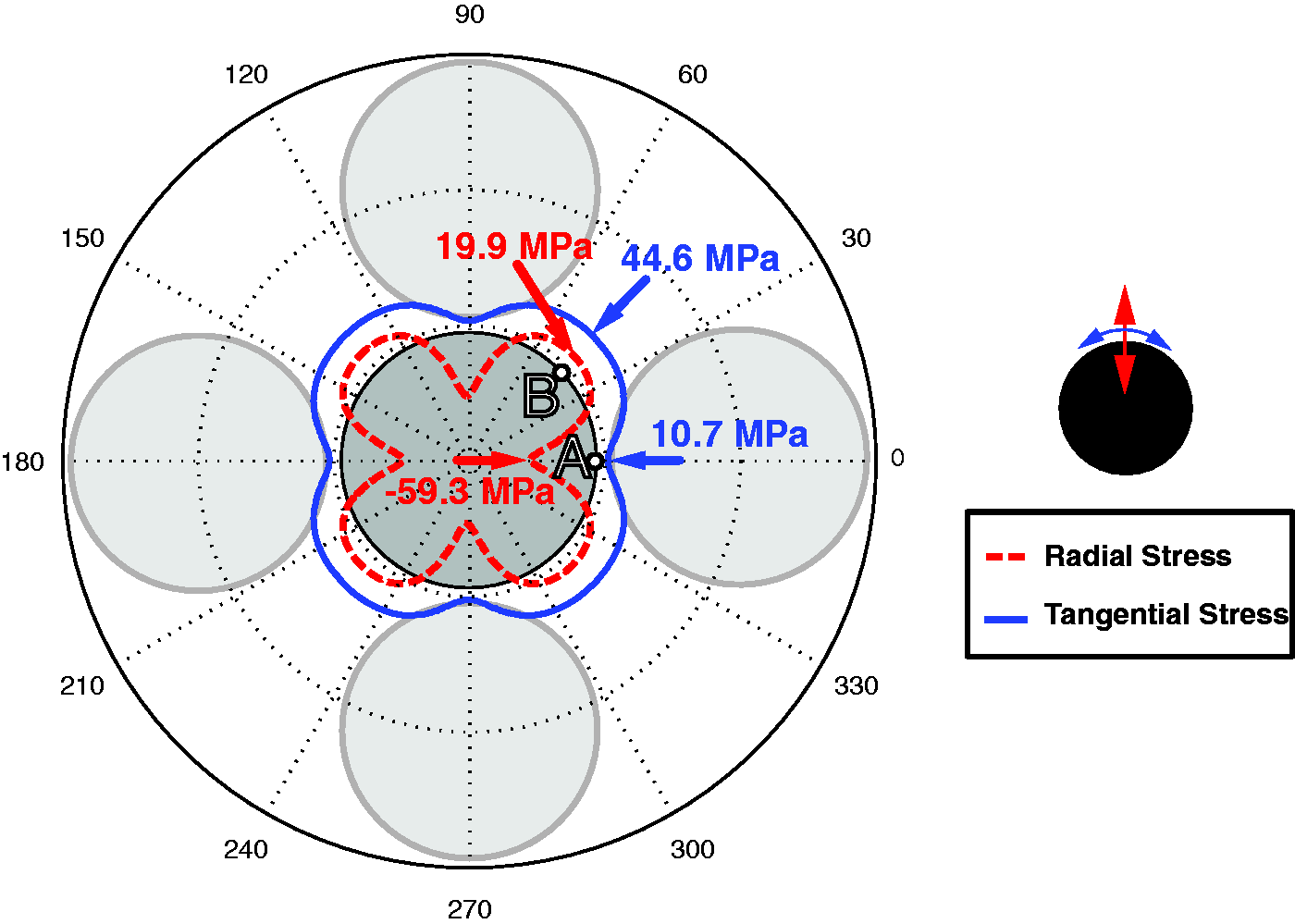
The evolution of radial and tangential stresses with increasing inter-fibre spacing is shown in Figure 10, where a large variation in the nature and magnitude of the stress around the circumference of the fibre is evident for small inter-fibre spacings. This variability of stress around the fibre circumference decreases as this spacing increases, eventually converging to constant compressive radial and tensile tangential stress states of similar magnitude as the inter-fibre spacing increases. For the initial small inter-fibre spacings, the plotted stress states form a quatrefoil shape (Figure 10(a) and (b)), where the lowest values of radial and tangential stress are located at the point of minimal inter-fibre spacing, while the peak tensile stresses are located at 45° to the axis joining the fibre centres, adjacent to the surrounding matrix-rich regions. These points on the fibre have been marked as points A and B respectively in Figure 9. These two points were used as the main points of interest for the interfacial region residual stress investigation.
The evolution of radial and tangential stresses with increasing inter-fibre spacing.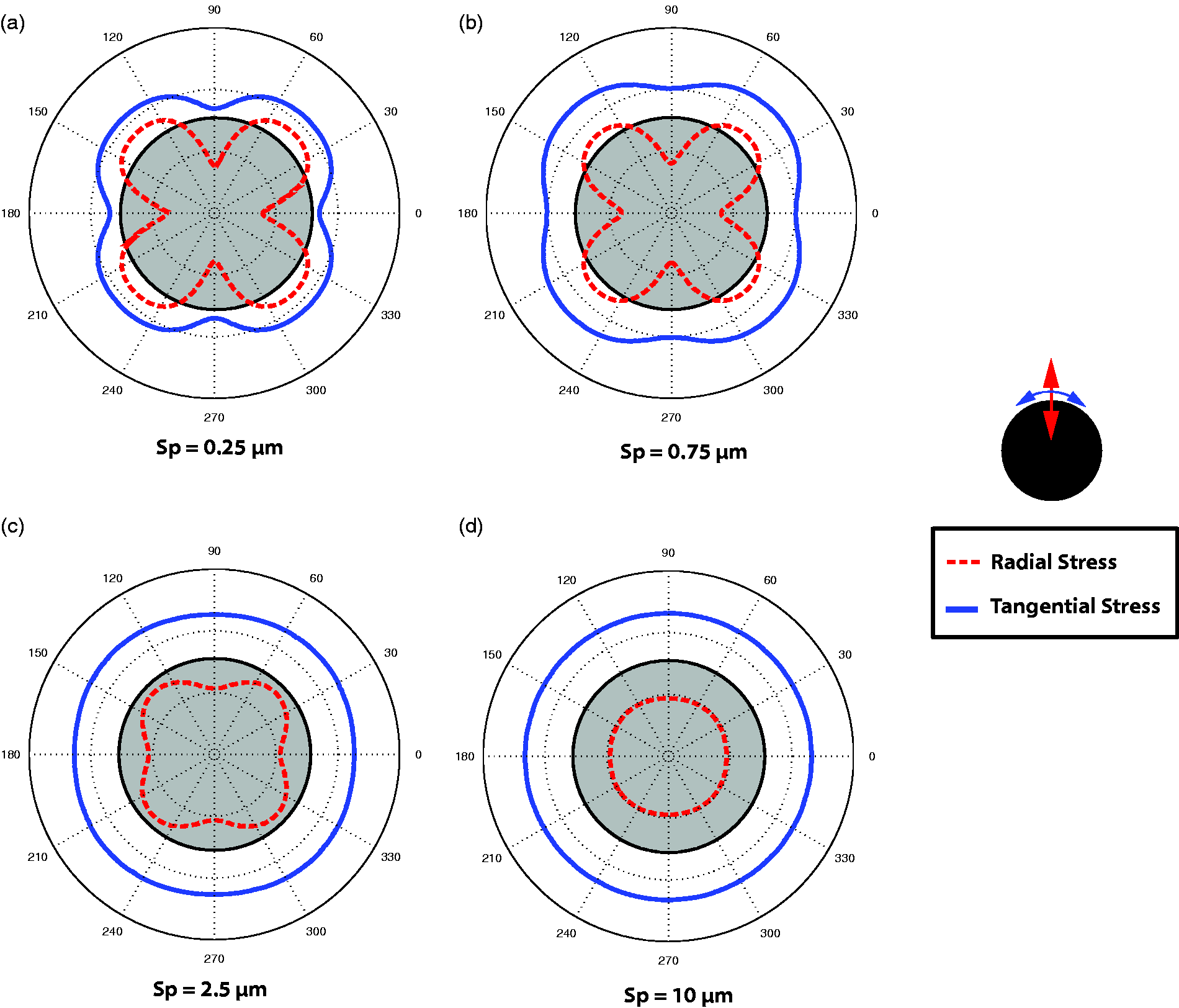
The values of the radial and tangential residual stresses for points A and B are plotted in Figure 11 for the range over inter-fibre spacings (Sp) investigated in the thermal cooldown models. The residual stress at the point A is a combination of compressive radial and tensile tangential stress over the full range of inter-fibre spacings. The radial stress at the point B undergoes considerable change as the inter-fibre spacing increases, changing from a tensile to a compressive state over the range of spacings investigated. The tangential stresses at point B remain tensile throughout, with a reasonably linear decrease in tensile stress magnitude as the inter-fibre spacing increases. None of the examined stress states described in this section caused plastic deformation in the matrix material.
Radial and tangential residual stress values for points A and B for the range of investigated inter-fibre spacings.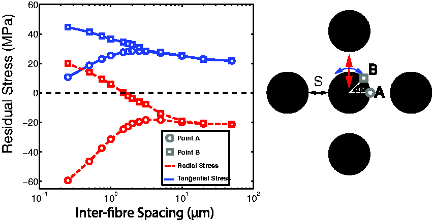
Simulated indentation results
The various interfacial region stress states determined from the cooldown models for the regions of interest A and B were applied to the bulk nanoindentation substrate through a combination of tensile and/or compressive outer boundary substrate displacements, as required. The radial stresses were applied perpendicular to the plane of symmetry while the tangential stresses were applied parallel to this plane as highlighted by the coordinate system in Figure 4. The calculated indentation properties were found to be largely insensitive to the Berkovich tip orientation relative to the radial and tangential directions, with hardness and modulus varying by a maximum of 2% and 1.5%, respectively, across the full range of stress states investigated when the indenter orientation was rotated by 90°.
The effect of the residual stress states determined at point A on nanoindentation parameters is shown in Figure 12(a). The substantial change in stress state at point A over the range of inter-fibre spacings from 0.25 to 3 μm leads to a substantial shift in the normalised indentation parameters over the same range of spacings. For the smaller inter-fibre spacings, the compressive radial stress was the dominant component of the in-plane stress state. This results in an increase in normalised hardness by up to 4.9% for an inter-fibre spacing of 0.25 μm. This is due to the increase in peak load required to reach the constant indentation depth, and a decrease in the normalised contact areas for the small inter-fibre spacings. As the inter-fibre spacing increases, these trends in peak load and area begin to reverse, leading to a reduction in the normalised hardness values. For inter-fibre spacings greater than 3.1 μm, the normalised indentation parameters begin to approach the values of the non-prestressed model, and eventually converge to final values as the effect of the surrounding fibre microstructure becomes negligible.
Normalised indentation parameters plotted versus inter-fibre spacing for (a) point A and (b) point B.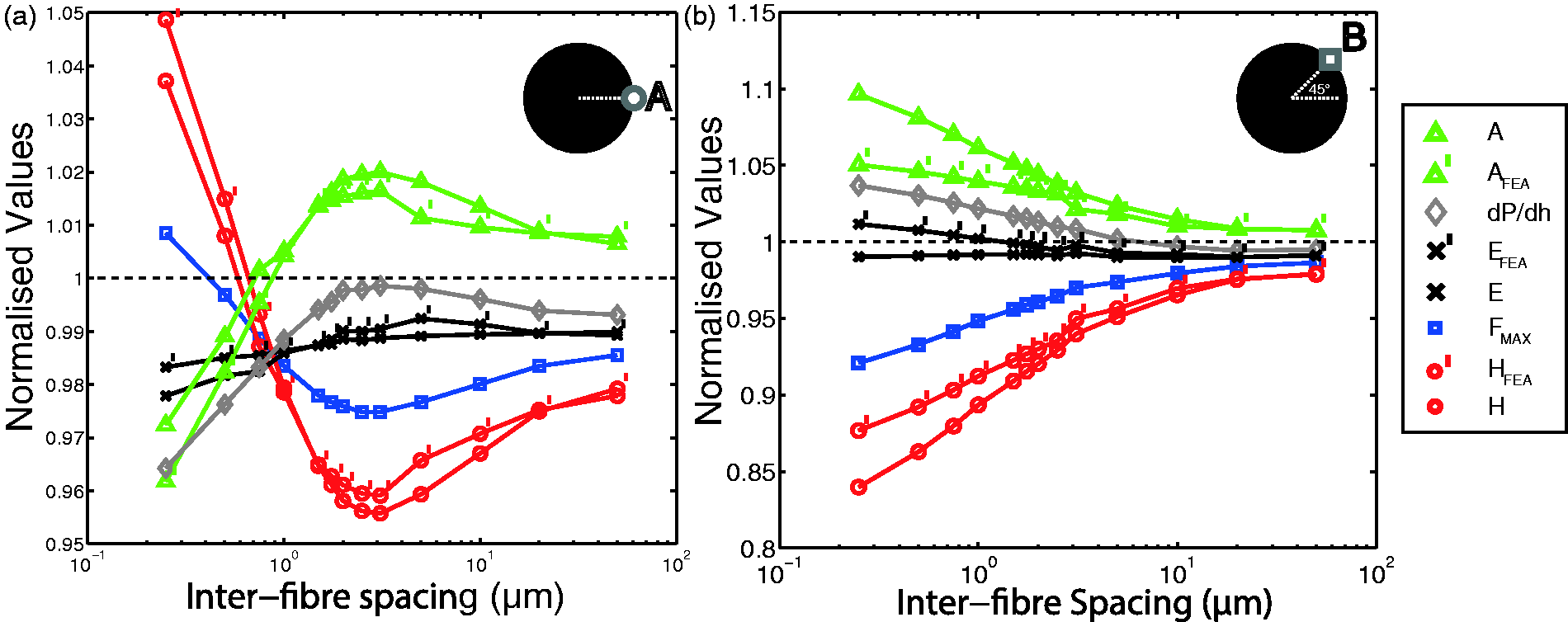
The normalised nanoindentation parameters for the stress states at point B are plotted in Figure 12(b). For the very small values of inter-fibre spacing (< 2 μm), the radial and tangential stresses at the point B are in biaxial tension. The largest deviation of the normalised nanoindentation parameters is also shown to occur over this range of inter-fibre spacings in Figure 12(b). As the inter-fibre spacing increases, the radial stress at the point B becomes compressive and the values of the normalised nanoindentation parameters begin to converge to the same values as those determined at point A for large inter-fibre spacings.
The results for the points A and B indicate that the effect of the residual stress is minimised for the cases when the radial and tangential stresses are roughly equal and opposite in magnitude, for example at the point of interest A with an inter-fibre spacing of approximately 1 μm, and for the homogenised stress state at large inter-fibre spacings. It is also interesting that the variation of the normalised nanoindentation parameters was much larger for the stress states at the point B than for those determined at the point A. This is due to the combination of compressive radial and tensile tangential stresses found at the point A over the full range of inter-fibre spacings. This is an important finding, as the point B is adjacent to a matrix-rich region, and therefore would likely be an advantageous region for carrying out experimental grid indentations travelling from one constituent to the other. However, despite these trends in the hardness property, the normalised indentation modulus values were largely insensitive to the interfacial stress states, only deviating by 2.2% and 1.1% from those of the non-prestressed substrate for points A and B respectively.
The plastic strain fields below the indenter tip for the pre-stressed substrates corresponding to an inter-fibre spacing of 0.25 μm are shown in Figure 13 for the points A and B. These have then been compared with the plastic strain field for the non-prestressed substrate. It can be clearly seen that the large in-plane radial compressive stress at point A for this inter-fibre spacing has a noteworthy effect on the size of the plastic strain field below the indenter tip at the maximum indentation depth. This compression increases the constraint effect of the surrounding material on the indentation stress field and reduces the overall volume of plastically deformed material in the substrate substantially. This sub-surface constraint directly increases the material’s resistance to permanent plastic deformation and is the underlying mechanism responsible for the apparent increase in indentation hardness values shown in Figure 12(a) for very small inter-fibre spacings at point A. Conversely, the biaxial tensile stress state at point B reduces the bulk matrix constraint on the indentation stress field, allowing a greater volume of plastic flow in the material as shown in Figure 13 at the maximum indentation depth.
The 1% equivalent plastic strain boundary for the non-prestressed substrate and the stress states at point A and point B for 0.25 μm inter-fibre spacing.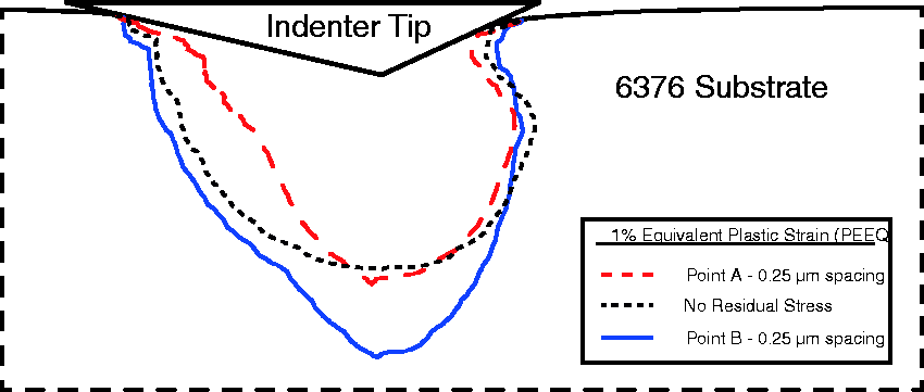
Concluding remarks
An important comparison can be made between the trends determined in this numerical analysis and those previously reported from experimental observations. The results indicate an apparent decrease in hardness of the matrix pockets with the existence of residual stress due to the presence of equibiaxial tension following thermal cooldown. Previous experimental work 5 has reported an increase in the in situ hardness of the matrix in comparison with the bulk matrix material, which is inverse to the trend reported in this numerical analysis. Thus, this experimentally reported change in in situ material behaviour cannot be attributed to the existence of residual stresses in the in situ matrix material. While this reduction in hardness was somewhat expected due to the tensile nature of the residual stresses in these regions, the quantitative reduction of the property is of interest. The existence of residual stress in these regions could in fact lead to underestimation of the true variation due to factors such as changes to the in situ polymer matrix cross-linking process during curing, and interfacial reactions with fibre treatments. This underestimation is more likely to occur when comparing bulk and in situ material, as opposed to comparing different in situ microstructural regions.
For the vast majority of interfacial region stress states considered in this analysis, the hardness decreased as a result of the residual stress. The only cases that led to an increase in indentation hardness were at the point of interest A for very small inter-fibre spacings (≤ 0.5 μm). As this point of interest is located between fibres at the point of minimal inter-fibre spacings, it is highly unlikely that these regions would be considered suitable for experimental grid indentations due to other experimental problems such as fibre–matrix relief 38 and sub-surface fibre constraint effects.5,8,31,32 Importantly, the results show that the potential for large compressive residual stresses present in the microstructure to increase the indentation properties is nullified by perpendicularly acting tensile stresses in these regions.
Thus, similar to the matrix pocket results, there is a potential for hardness of the interfacial regions (or ‘interphase’ material) to be underestimated due to dominant tensile stress which exists in the majority of experimentally suitable interfacial regions. These underestimations of the hardness property occur whether the contact area is inferred using the Oliver and Pharr analysis or directly from the simulations contact. However, the results from the current investigation can also be used to aid future experimental studies, as the microstructural interfacial regions where indentation properties can be determined, free from the influence of residual stress, have been determined.
The indentation modulus was largely insensitive to the state of residual stress in the substrate. This property only varied by a maximum of 2.2% for the stress states investigated. Therefore, the indentation modulus is the recommended indentation property to be determined when carrying out a comparative parametric analysis between microstructural regions which are affected by the existence of thermal residual stresses. The use of the hardness property for comparative investigations of this nature may add some unnecessary bias or variation to the already problematic scatter associated with experimental nanoindentation.
Footnotes
Declaration of Conflicting Interests
The author(s) declared no potential conflicts of interest with respect to the research, authorship, and/or publication of this article.
Funding
The author(s) disclosed receipt of the following financial support for the research, authorship, and/or publication of this article: The authors wish to acknowledge the funding provided by the Irish Research Council (IRC). This work was also conducted under the framework of the Irish Government’s Programme for Research in Third Level Institutions Cycle 5, National Development Plan, 2007–2013, with the assistance of the European Regional Development fund. This publication has emanated from research conducted with the financial support of Science Foundation Ireland (grant number SFI 13/1A/1833).