
Abstract
The foundations for a multiscale numerical framework for composites, that can assist in the design of composites structures, have been laid in this study. Fibre tensile and shear properties were investigated experimentally, and subsequently modelled using the laminate theory. The interface properties of a flax/polypropylene and a flax/epoxy system were determined using microbond tests combined with micromechanical models, and properties from transverse tensile tests. These properties were used in numerical models of the microbond test, and good agreement with experiments was obtained for both systems. When the interface and fibre properties were used in numerical models of single flax yarns impregnated with polypropylene or epoxy resin, the stiffness behaviour showed good agreement with experiments for flax/polypropylene and flax/epoxy systems. The peak stress prediction from the flax/polypropylene numerical model was only 6.2% lower than the experimental average of 24.33 MPa. The flax/epoxy model, however, predicted a peak stress value of 85.6 MPa which was 20.6% higher than the experimental value of 70.9 MPa. The properties obtained from this study, along with the methodology, can be used to estimate macro-scale strengths of composite members in structures for different layups and loading conditions.
Introduction and background
Fibre composites are used in a wide range of structural applications due to their high strength and stiffness, low density, tailorability to suit application needs and other positive traits. Among structural fibre composites, carbon- and glass-based composites are the most widely used. There are concerns regarding disposability of these composites at the end of their service life, which is important in light of legislation regarding waste disposal in the EU and Japan, as well as other countries. 1 Natural fibre composites (NFCs) display several positive traits, primary of which are their low density, renewability of sources, as well as the fact that they can produce fully biodegradable composites when combined with polymers such as poly(lactic acid). Among natural fibres, flax, hemp, kenaf and ramie display the best mechanical properties, 2 but flax and hemp are more widely cultivated and available in forms suitable for composite production. Recent studies 3 have even shown flax fibres in composites to display properties similar to glass fibres, after being subject to a cellulose-based treatment.
Early investigations into the chemical, mechanical and morphological properties of wood and other natural fibres have revealed natural fibres to be complex structures, composed of multiple layers, and each layer in turn composed of different constituents.4–8 The complexity, as well as scatter in their mechanical properties makes prediction of their properties challenging. The layers of natural fibre cell walls consist of oriented cellulose microfibrils (CMF) embedded in a hemicellulose-lignin matrix. The fibres can then be considered as laminated composite cylinders composed of an assembly of unidirectional (UD) lamina, and the classical lamination theory (CLT) has been applied to predict their mechanical behaviour in the elastic domain.5,9–12 From among the various proposed models for elastic fibre behaviour,5,9–11,13 one can draw out a generalised model as illustrated in Figure 1. In this model, each fibre is composed of multiple layers referred to as middle lamellae (ML), P, S1, S2 and S3, with a hollow lumen in the centre. The ML and P layers are often combined and referred to as combined middle lamellae (CML).
11
The S2 layer occupies 60–70% of the fibre volume,14,15 and usually has CMFs with the steepest microfibril helix angle (MFA), due to which it has the most significant contribution to the longitudinal modulus. It is hence common to model the fibre modulus by applying a composite lamina treatment to the S2 layer alone, and to calculate the variation in modulus with MFA of the CMFs in the S2 layer. In our study, we have considered S2-only-models, as well as models incorporating the other layers.
A generalised schematic of the arrangement of cell wall layers in natural fibres.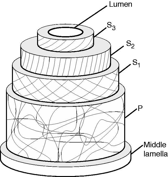
The dimensions of fibres present difficulties in performing direct tests on them. However, their longitudinal tensile properties can be obtained through single fibre tensile tests (SFTTs), and in-plane shear modulus of fibres can also been obtained using the torsion pendulum method.16,17
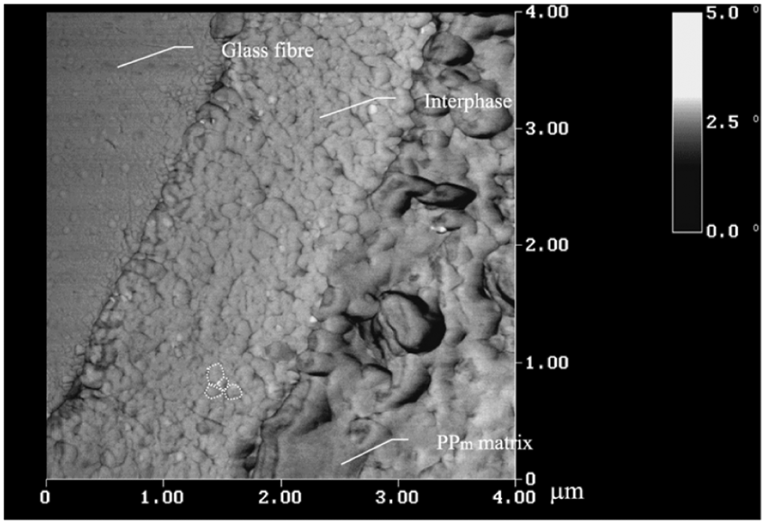
The role of the matrix in most load-bearing applications of composites is to transfer external load to the fibres. Hence, the bonding of the fibres with the matrix or resin, and the associated interface/interphase are important aspects of composite design. The interface is a line or region with no thickness, whereas in most composites, a separate interphase layer exists between the fibre and matrix phases. This layer originates either due to the fibres acting as crystal nucleation surfaces, or due to the absorption of curing agents from the matrix by the sizing agents present around the fibres (Figure 2). Although the interphase region has a definite thickness, for purposes of modelling and analysis, it is often simpler to assume the thickness to be negligible compared to the fibre and matrix dimensions.
AFM image showing the interphase between a glass fibre and a polypropylene matrix.
18
Microscopy of flax fibres has shown at least some of the species to have polygonal (mostly irregular hexagons) cross sections.19,20 Charlet et al. 21 have argued that the error in fibre strength estimation due to the assumption of a circular, rather than hexagonal cross-section, is insignificant compared to the scatter in properties due to the spread of fibre diameters. However, the meshing of fibre geometry in numerical models of impregnated yarns is made much easier with the assumption of a hexagonal cross-section.
In this paper, we have studied both the fibre and interface properties through tests and analyses. In addition to this, we have also investigated the behaviour of resin-impregnated single yarns, using FE models incorporating both the yarn geometry, as well as the fibre and interface properties obtained. The models of resin-impregnated yarns are a step towards multi-scale analysis of full fabric composites, which is the ultimate aim of future research which will derive from this study.
Materials, characterisation and methods
Matrix material properties.

Optical microscopy was used to characterise fibre and yarn diameters, and to measure yarn helix angles. Material densities were measured using the Archimedes method with canola oil as the immersion medium.
Fibre properties
Outlined below are the experimental techniques used to characterise flax fibre properties, methods used to analyse test data, and approaches taken to model fibre properties. The methodology followed in performing tests, obtaining properties from tests, and using them in numerical models is illustrated in Figure 3.
Flow of data from various experiments to the numerical models.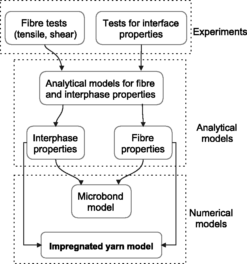
Single fibre tensile tests and fibre shear properties
A sample of fibres was separated from fabric yarns, and mounted on paper frames with square cutouts in the middle. For each specimen, a single fibre was positioned at the centre of these paper frames, and bonded to the paper using two droplets of epoxy. These droplets were placed at the top and bottom edges, respectively, of the square cut-out to a length suitable for the gauge length used. Four different gauge lengths, from 10 to 25 mm, in increments of 5 mm were used, with at least 60 specimens tested for each gauge length. Fibre diameters were measured at six locations along the tested length of the fibre using an optical microscope, and the average value was used to calculate the fibre strength and longitudinal elastic modulus. For our calculations, we have assumed that the fibres have a circular cross section, and also that they have no lumen or defects. The fibre diameters were normally distributed with a mean of 18.9 µm and a standard deviation of 4.5 µm. The SFTTs were performed with a 10 N load cell at a rate of 1 mm/min using an Instron 5567 universal testing machine (UTM), which has a crosshead position resolution of 0.054 µm. The maximum fibre failure load among all fibres tested was 0.7 N, but a 1 N load cell that was available was not used since a safety margin was needed for the weight of the grips, and to prevent overloading the load cell. Specimens were not pre-loaded before the commencement of data recording.
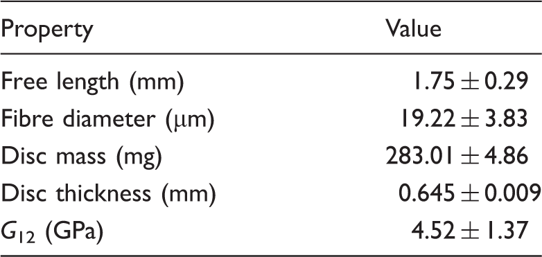
Fibre longitudinal shear properties were obtained by the torsion pendulum method,16,17 testing 25 specimens in total. Specimens were prepared for testing in the vertical disc configuration, as shown in Figure4. For the ideal configuration in the figure, the shear modulus of the fibre can be calculated from moment of inertia principles using the equation
16
Ideal arrangement of fibre and disc for a vertical torsion pendulum test shown in (a) and (b), while configuration used in experiments is shown in (c).

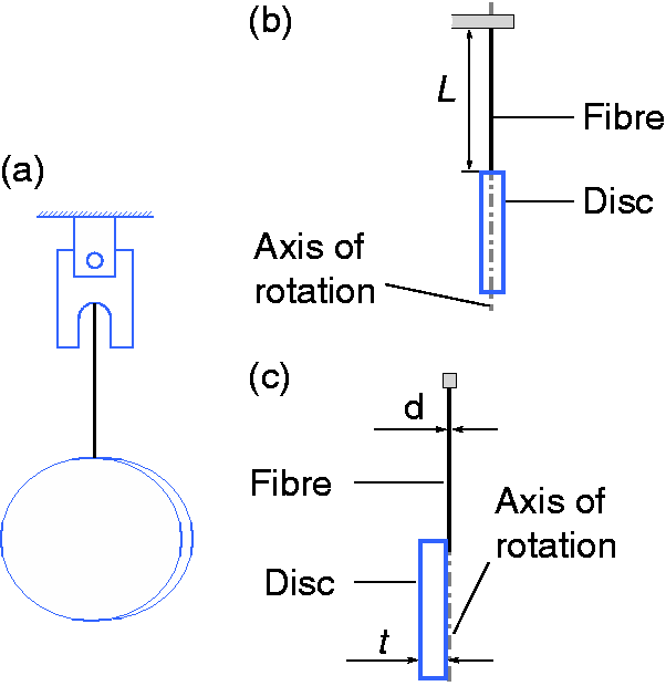
Circular discs of 25 mm diameter were cut out from a sheet of PP approximately 0.38 mm thick, numbered to correspond to a specimen, and weighed. The top end of the fibre was then glued down to the bottom of a paper frame, and the bottom end to the top of the disc, both using epoxy. The specimens were prepared such that the free length of the fibre, between the paper frame and the disc, was approximately 2 mm. Prior to testing, images of all the specimens were recorded using a microscope at 32× magnification to measure the fibre free length, and at 230× magnification to measure the diameter. The diameter was averaged from six different measurements for each fibre.
The test itself was performed in an enclosed chamber with a transparent door, containing a stand holding a grip. The specimen was mounted in the grip using the paper frame, following which the door was closed. A mechanism was devised, which could be operated from the outside and could twist the disc about the fibre axis. A half rotation was applied to the disc, following which it was released. The oscillations of the specimens were recorded on a video camera, and the shear modulus of each fibre was then calculated using equation (2).
Fibre strength statistical modelling
Two-parameter Weibull distributions were used to approximate the distribution of the fibre strength values for each set of gauge length data. Q–Q plots can be used to compare two distributions, and in this case it was used to compare the distribution of fibre strength values from experiments for a certain gauge length to Weibull models with different parameters. Fibre strength data for any gauge length usually lies along a straight line representing the corresponding Weibull distribution, with the slope and intercept of the line giving the Weibull scale and shape parameters α and β. The parameter α is also known as the characteristic stress σ0, and is the characteristic fibre strength value for any given gauge length.
Weibull scaling was used to scale the Weibull strength from a particular gauge length to other gauge lengths. It was found that scaling from the 20 and 25 mm data leads to over-prediction of strength values at 10 and 15 mm, while scaling from the 10 and 15 mm leads to an under-prediction of strengths.
Such disparity between scaled data and experimental results has been observed in the case of carbon fibre,
26
glass fibre
27
and hemp fibre.
28
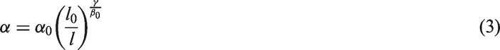
A modified Weibull scaling law
27
of the form
Fibre analytical modelling
Properties used for construction of CLT models of fibre properties.
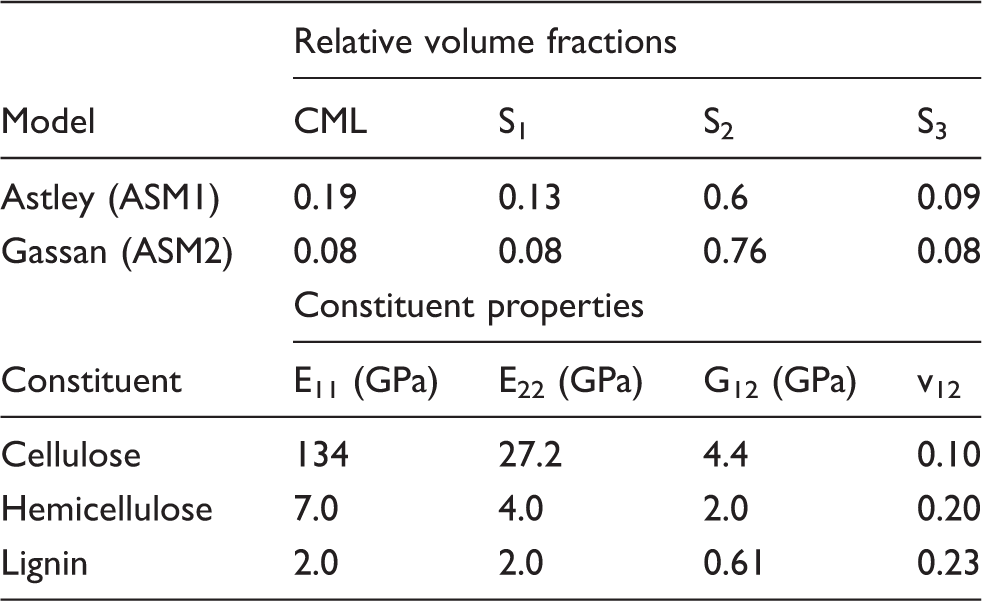
The lamina model consisted of CMF in a matrix of lignin and hemicellulose, and the properties for the components were combined from a range of sources.5,11,31,32 These properties are listed in Table 2. Rule of mixtures was used to calculate the longitudinal properties of the lamina corresponding to the different layers, and the modified Halpin–Tsai equations 33 were used to calculate the transverse properties. The constitutions of the different layers as reported by Harrington et al. 11 were used for the calculations. Two different values for volume fraction (Vf) of CMF in the S2 layer were considered: 0.65 and 0.7, while the volume fractions of the CML, S1 and S3 layers were held constant. The engineering stiffness matrix for the lamina, rotated stiffness matrices corresponding to the layer helix angles, and the stiffness and compliance matrices for the assembly of layers were calculated using the classical lamination theory. For the S2 layer, a possible range of helix angles between 2°and 30°13,34 was considered. The longitudinal, transverse and shear modulus values for each assembly were obtained from the corresponding assembly compliance matrix.
Interface properties
Testing
Several experimental techniques have been proposed 35 to obtain the interfacial shear strength (IFSS) of composites, among which the microbond technique 36 is one of the more commonly used techniques due to two reasons (i) ease of preparation of the specimen, and (ii) very small or no meniscus region as compared to disc-shaped specimens. The usual treatment applied to obtain the interface strength in microbond tests is to assume a uniform stress over the interface, and then to calculate the shear strength from the load. However, it has been shown that 37 stress concentrations exist in microbond specimens. Analysis using variational mechanics models 37 and shear-lag models 38 is capable of accounting for these stress concentrations.
The microbond test configuration is shown in Figure 5, where a fibre is pulled upwards while a droplet surrounding it is restrained from moving up using a set of parallel blades or an annular ring. The angle φ made by the parallel blades with the axis of the fibre is called the blade/vice angle. In order to save on computational time, previous studies39,40 have used quarter model finite element (FE) representations of the test geometry. As explained by Aghdam and Falahatgar,
41
this geometry can then be combined with a maximum principle stress criterion
42
when the interphase is brittle, or with a quadratic failure criterion in the case of softer interfaces.41,43,44
(a) Test configuration for a microbond test – l is embedded length of the fibre, h is height of the droplet, and φ is the vice angle, and (b) numerical model setup with analytical rigid part representing the vice block.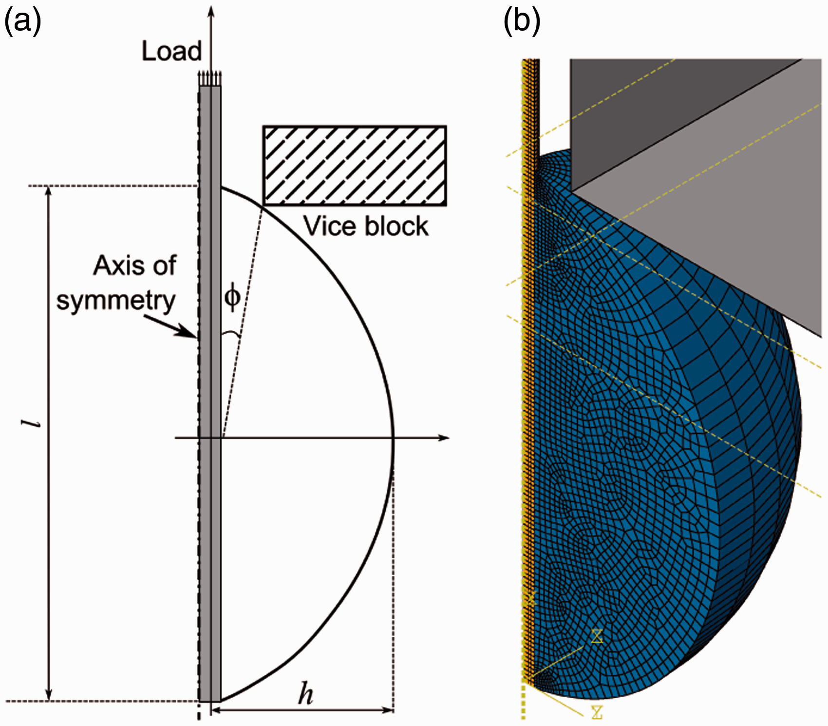
Shear behaviour of the interface for both composite systems was analysed using the microbond technique. Flax/PP specimens were prepared by tying a knot of a thin PP strand around a flax fibre, followed by heating at 190℃ for 10 min. The procedure for flax/epoxy specimens involved applying a single droplet of epoxy resin onto a flax fibre, using a glass fibre as an applicator. It was found that applying the resin 30 min after mixing with hardener made preparation easier, since the viscosity was higher.
Prior to testing, one end of the fibre was glued to the bottom of an aluminium tab using high stiffness cyanoacrylate glue, such that the distance from the bottom of the tab to the top of the droplet was about 1 mm. After capturing the fibre and droplet geometries using an optical microscope, the top end of the tab was mounted in an Instron 5567 UTM, which has a crosshead position resolution of 0.054 µm. The vice grips were mounted on a holder directly below the specimen, with the fibre positioned between the vice grips, and the grips were then brought in until they nearly touched the fibre. The test was then started, with the cross-head speed set to 0.1 mm/min, and the load-extension data were recorded by the computer controlling the UTM. A 10 N load cell was used to perform the microbond tests.
The vice angles were not recorded for the experiments, and it was difficult to control and measure the vice angle with the experimental setup used. Thirty specimens were tested for the flax/PP system, and 23 specimens for the flax/epoxy system.
Analysis
Micromechanical analysis of the microbond test data was done using the Scheer–Nairn model
37
and the Le Duigou model.
38
Thermal stresses are considered in both these models, and the values for coefficient of linear thermal expansion coefficients used were38,45,46 (i) flax – 1 × 10
Normal behaviour of the interface was derived from transverse tensile test data using the modified Cooper–Kelly model.
47
The equation is of the form

A quarter geometry representation of the microbond test (Figure 5(b)) with symmetry boundary conditions was constructed and solved using ABAQUS FE explicit solver. The droplet geometry was generated by revolving a circular arc, and an anaytical rigid body was used to represent the vice. The fibre diameter used was 19 µm and the droplet h and l values (Figure 5(a)) from average optical microscopy results were 0.5 and 0.22 mm for flax/PP and 0.27 and 0.09 mm for the flax/epoxy system. Fibre properties corresponding to 9° CMF helix angle were calculated using the CLT-based ASM2 model, and CMF Vf = 0.7.
The general contact algorithm
48
was employed to handle contact between the fibre, droplet and vice parts, and a cohesive surface interaction with damage was applied to the fibre–matrix interaction. Stiffness for the cohesive interaction was calculated using the linear law
49
for certain simulations, and the damage was specified by applying the experimental interfacial normal strength (IFNS) and interfacial shear strength (IFSS) values to a quadratic traction criterion. The criterion used in ABAQUS is of the form
48

Impregnated yarn failure
Manufacture and testing
In order to manufacture the impregnated yarn specimens, individual flax yarns were extracted from the fabric, and stuck down at the top and bottom to strips of tape, parallel to and separated from other yarns, to create a parallel array of yarns. To produce the epoxy-impregnated yarns, as shown in Figure 6(a), the array of yarns was placed on a vacuum bag sitting on a glass base. Epoxy resin was poured between the yarns, with care taken to avoid air entrapment, after which another sheet of vacuum bag was used to cover the yarns. A heavy steel plate was then used to apply pressure. After room-temperature curing, the assembly was post-cured in an oven at 70℃. As for the PP-impregnated yarns, another array of yarns was prepared, sandwiched between two teflon sheets, and subjected to compression at 185℃ and a pressure of 0.5 MPa for 10 min.
Schematic diagram of manufacture of impregnated yarns.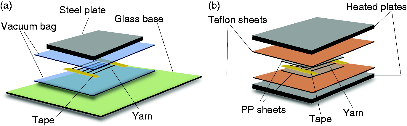
To produce test specimens, thin strips approximately 100 mm long and 5 mm wide were cut from the produced sheets, with one yarn in the middle of each specimen (Figure 7). Since the polymers used were transparent/translucent, yarn diameters could be measured by optical microscopy with the specimens lying down flat. Sections corresponding to each specimen were also prepared from the excess lengths of the produces sheets, and mounted in epoxy to produce discs of epoxy containing the sections in them. These discs were then ground and polished to measure yarn diameters by directly observing their cross-sections as well. The median yarn diameter, assuming a circular cross-section, was 237 µm.
Impregnated flax/PP yarn specimen (a) cross-sectional image and (b) specimen in grip.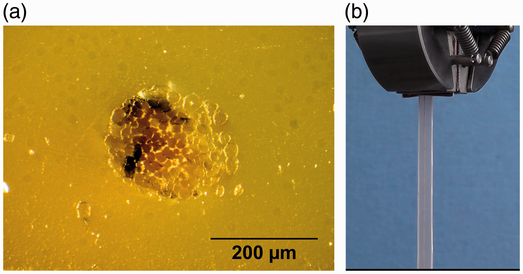
Testing of the specimens was performed in an Instron 5567 UTM, with a 50 N load cell, and using 2 KN tensile testing grips. The crosshead speed used was 5 mm/min, and the specimens were not pre-loaded before the start of data recording.
Numerical simulation
The helix axis of flax yarns was measured using optical microscopy to construct a helix curve. A plane normal to this helix was then constructed, on which a number of hexagons were drawn and packed into a circle by modifying a circle packing code.
50
Fibre diameter distribution data from SFTT measurements were used to generate the hexagons. These hexagons were then swept along the helix to generate the yarn geometry. A part composed of matrix material surrounding the fibres was generated from the same geometry by sweeping a circle, followed by a Boolean cut operation. This part was used for easier meshing of the matrix region immediately surrounding the fibres (Figure 8(b)). The fibres and surrounding matrix part were then cut at the top and bottom, such that (i) the overall length was equal to one pitch of the yarn, and (ii) the top and bottom ends matched. As in the impregnated yarns that were manufactured, the yarn was surrounded by a rectangular block of matrix, extending along the same length as the yarn itself (Figure 8(a)). The majority of the geometry operations were performed using the open source Salome package, with some end operations done in ABAQUS CAE.
Numerical model for simulation of impregnated yarn failure, (a) full cross section of model, and (b) detail of central area with yarns surrounded by matrix.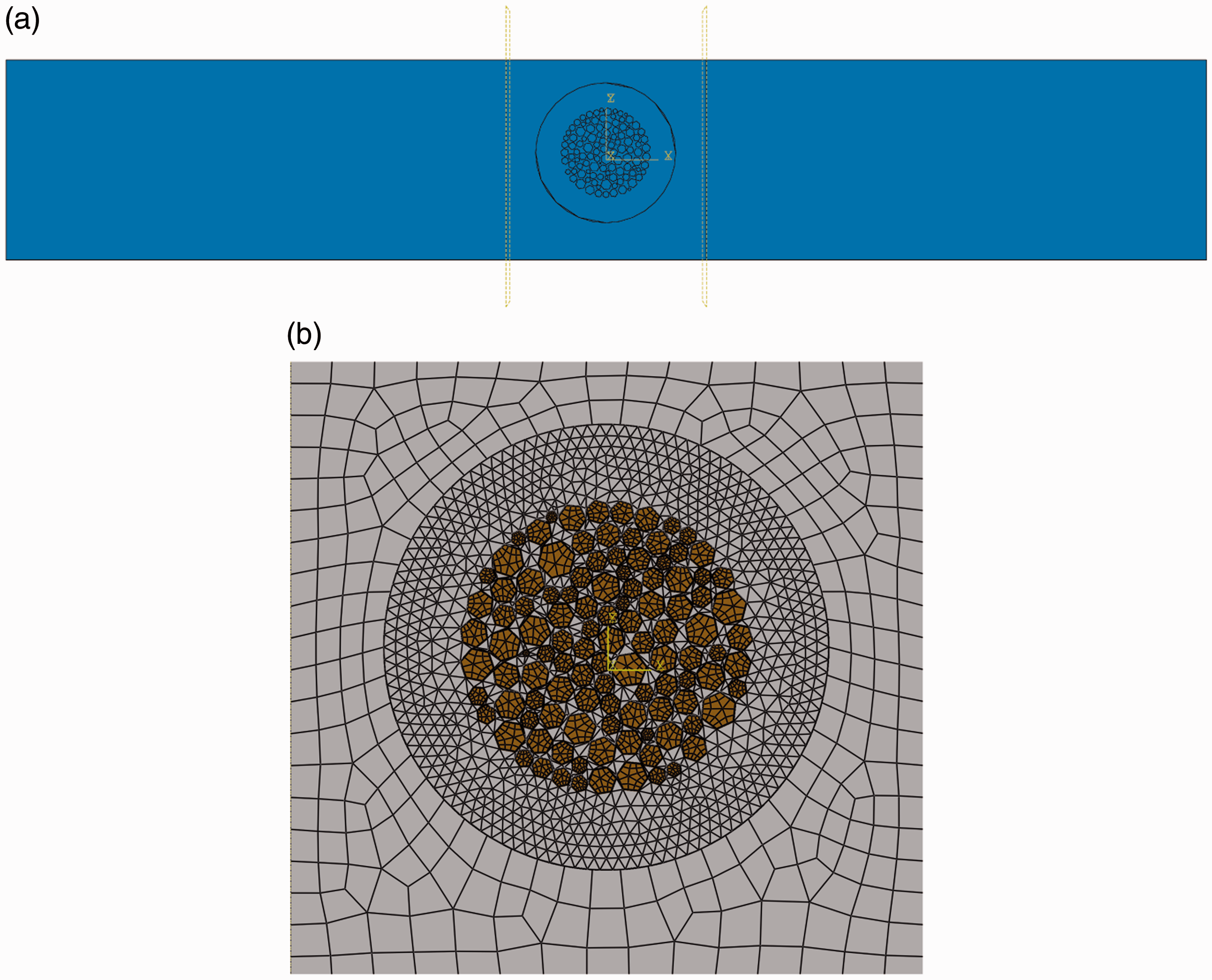
Flax fibre stiffness and strength values used in simulations.
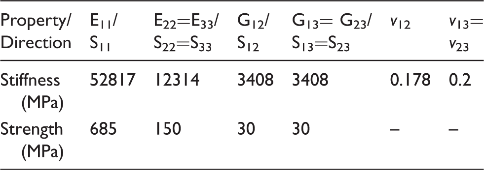
Note: E, stiffness; S, strength; 1,2,3, longitudinal, transverse and out-of-plane directions.
Longitudinal modulus and Weibull parameters for SFTT data from different gauge lengths.
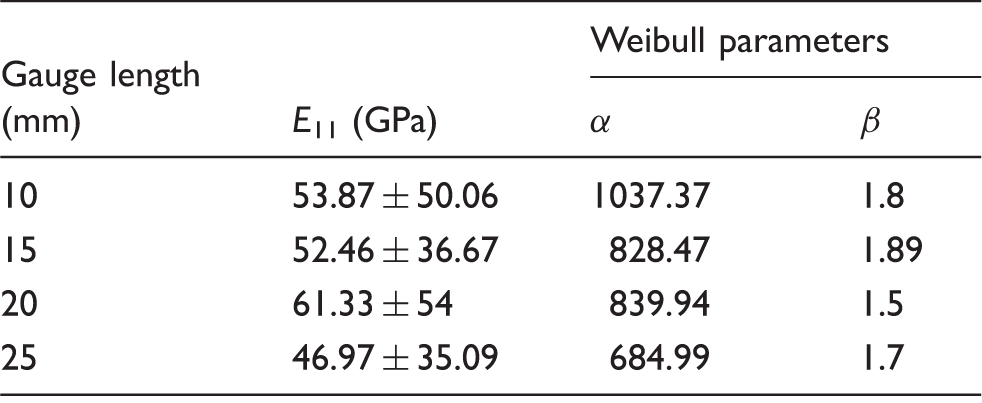
Note: α is the scale parameter, and β the shape parameter of the Weibull distribution.
The failure strain values for flax fibre elements were estimated from their stiffness and strength values (Table 3) using the CLT equations. 51 The tensile strength value for flax in the table was taken from the SFTT results (Table 4), while S22 and S33 were estimated from a study on transverse failure strengths for wood fibres over a range of cellulose microfibril helix angles. 52 The transverse strength corresponding to a helix angle value of 9°, which is the most common in flax fibres,53, 54 was indicated to be in the region of 150 MPa. The fibre shear strengths were estimated from the in-plane shear strengths of composite specimens using a simple Reuss model. For our composites, these lay between 38 MPa and 44 MPa, and the fibre shear strengths calculated were between 10 and 50 MPa. In the simulations, the shear strengths were set to an average of 30 MPa. For comparison, the shear strength value for glass fibres is in the region of 200 MPa.55,56
For both the fibre and matrix elements, the strains corresponding to the failure strengths were set to define the onset of plastic yielding. Damage was assumed to have occurred when any of the elements exceeded their failure strain or plastic strain values. A Hill yield surface
48
was utilised for implementation of the anisotropic plasticity-based failure for the fibre elements, and can be accessed through the *POTENTIAL keyword in ABAQUS. The Hill’s potential function can be expressed as


Cohesive properties with damage were assigned to the surfaces between the fibres and the matrix. The IFSS and IFNS values for flax/PP were 28.59 MPa and 10.95 MPa (Table 6), while for flax/epoxy, the values were 51.87 MPa and 28.38 MPa. The cohesive properties were assigned following the same method used in the microbond numerical models, with penalty-based contact stiffness. The IFSS values and contact stiffness used for each material system are the same as the corresponding values used for that system in ‘Sim 1’ to ‘Sim 3’ (Table 7) microbond models.
Frictional interactions were also added between the fibre and matrix surfaces, and between the fibres themselves, which would be activated in case of cohesive failure. Reported values of static friction coefficients for fibre–fibre friction are 0.22–0.49,57–59 while the values reported for wood-polymer combinations are between 0.3 and 0.5.60,61 In our models, the fibre–matrix friction coefficients and the fibre–fibre friction coefficients were assigned a value of 0.4.
While testing the impregnated yarns, a displacement rate of 5 mm/min was applied to the top of a 100 mm specimen. Our model represents a periodic unit in the middle of a specimen. Hence, the displacements applied to the top and bottom faces were reduced from 5 mm/min, in proportion to their positions relative to the full length of the yarn. Thus, the displacements applied to the top and bottom faces were


Results and discussion
As per the strategy outlined in the ‘Numerical Simulation’ section earlier, a hierarchical approach was applied – obtaining material properties at the micro-scale, linking them to analytical and/or numerical models, and then feeding these micro-scale properties into a larger scale model. Fibre properties were determined first, fit to Weibull distributions, and compared to predictions using CLT theory. The fibre properties were then used in simulations of the microbond test performed to determine the properties of the interphase. The properties of the fibre and the interphase were subsequently used to model the failure of matrix-impregnated flax yarns.
Fibre properties
SFTT data, shear data and Weibull fits
The average longitudinal tensile modulus data from each gauge length was corrected for slip inside the grips as outlined in the ASTM D3822 standard. The average of the corrected mean longitudinal modulus values from all gauge lengths (Table 4) is 52.28 GPa. This is in agreement with the mean values reported by other studies.15,53 There is a large scatter in the modulus values, but this is expected for natural fibres, due to varying properties and defect concentrations at different locations on a stem of a plant, and variations between fibres from different plants.
As explained in the methods section, fibre UTS values for each gauge length have also been calculated, along with Weibull fits for these values, as shown in Table 4.
For the flax fibre data in this study, a value of 0.78 for γ was found to give the best results when scaling from shorter to longer and vice-versa using the modified Weibull scaling method (Figure 9). In the figure, ‘WbCh’ plots the characteristic Weibull strengths at each gauge length, while ‘Wb10Sc’ – ‘Wb25Sc’ are the strengths obtained by scaling from characteristic values for gauge lengths 10–25 mm.
Weibull characteristic strengths by scaling from different gauge lengths. ‘WbCh’ – characteristic Weibull strengths at each gauge length, ‘Wb10Sc’ – ‘Wb25Sc’ – strengths obtained by scaling.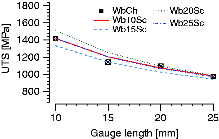
Fibre longitudinal shear modulus from torsion pendulum tests.
Interfacial strength properties from the analysis of microbond test data, and transverse tensile test data.
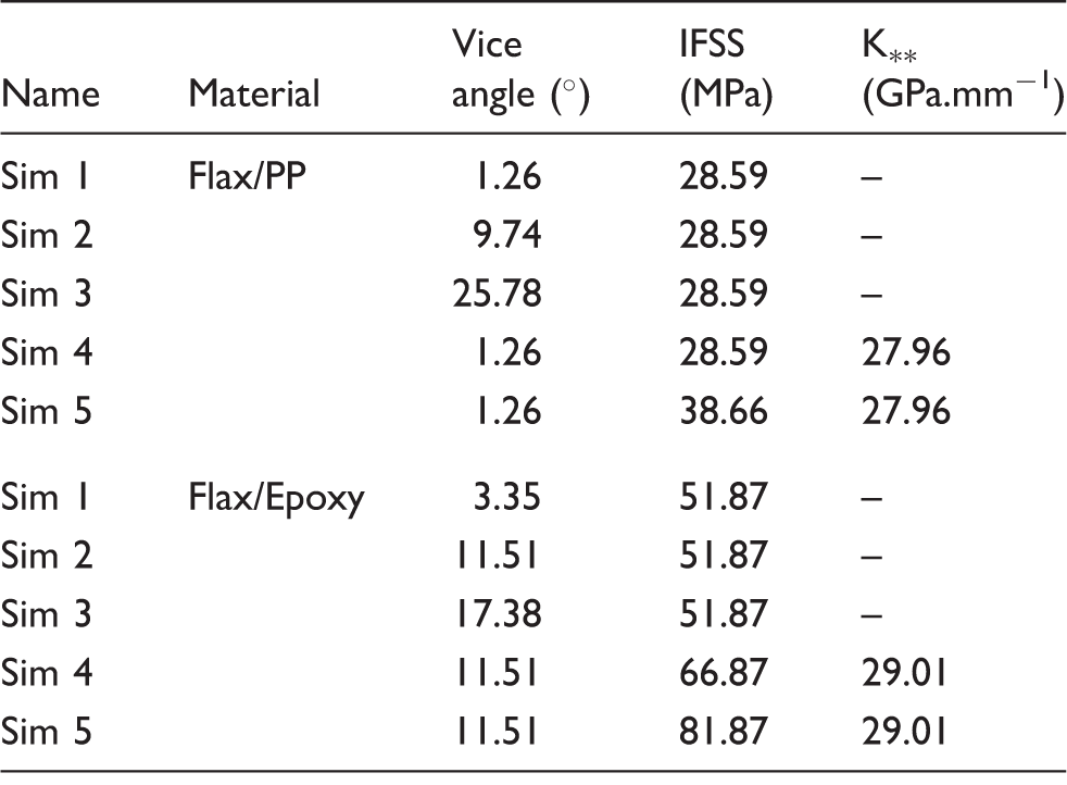
Parameters used for the flax/PP and flax/epoxy microbond models.
Note:
Fibre modulus analytical model
The longitudinal moduli predicted by the different laminate layup models are shown in Figure 10(a). From the SFTT tests, the average longitudinal modulus is 52.28 GPa. Previous studies54,53 have indicated that the MFA for flax fibres lies close to 9°. Among the different models in the E11 plots, the prediction using the ‘ASM2, CMF 0.7’ model lies closest to an E11 value of 52.28 GPa and MFA of 9°. This model has therefore been used for all subsequent numerical models requiring flax fibre properties.
Flax fibre modulus values as S2 only model, Astley model (ASM1), and Gassan model (ASM2), (a) E11 values, (b) G12 values. The ‘CMF’ value indicates the volume fraction of crystalline cellulose microfibrils considered to be in the S2 layer.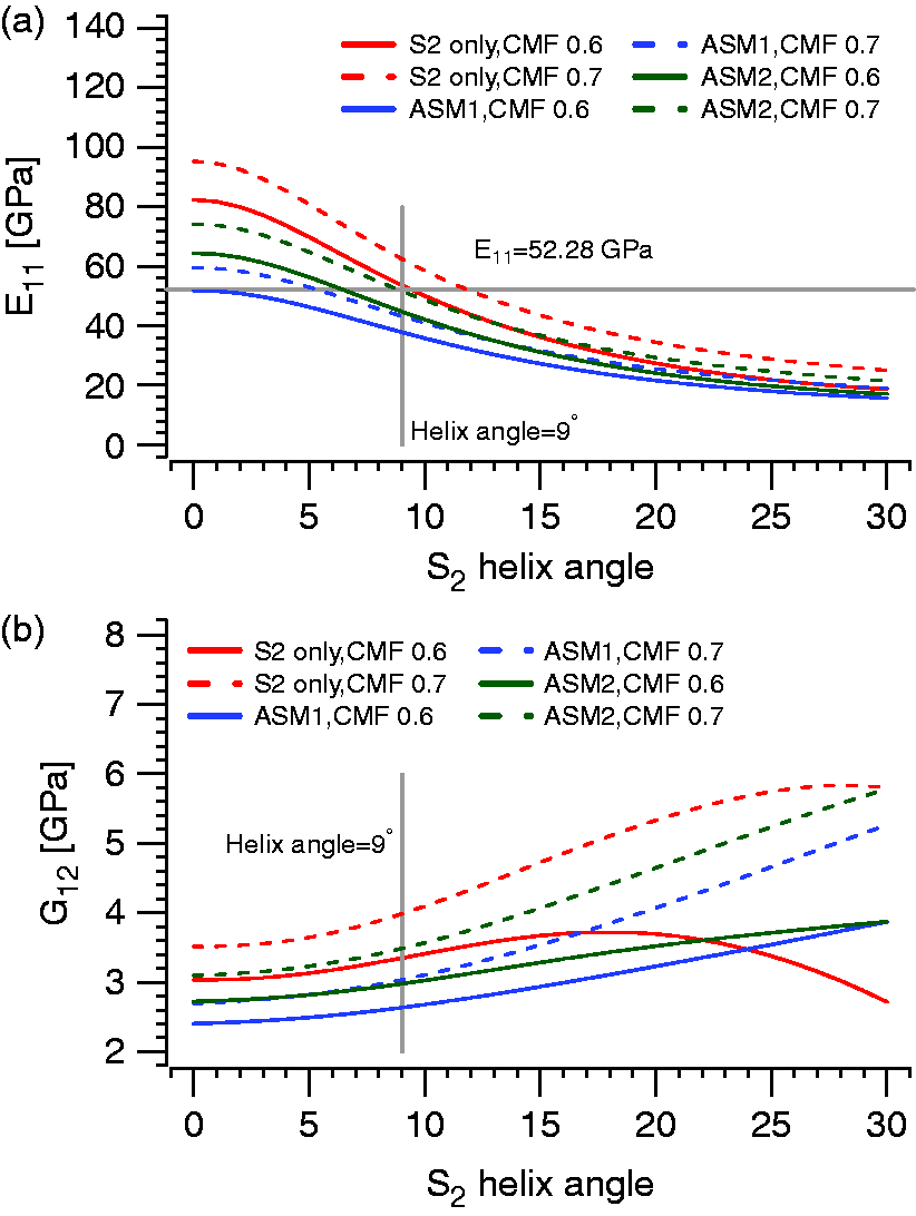
The shear modulus G12 predicted by the ‘ASM2, CMF 0.7’ at MFA of 9° is 3.48 GPa (Figure 10(b)), which is 22.9% lower than the mean value obtained from the torsion experiments, but is still within one standard deviation. The fact that the torsion pendulum experiment is very sensitive to errors in fibre diameter measurement (equation (2)) should also be taken into account. In the analytical model, the fibre is assumed to be a laminated assembly, with direction 1 being along the length of the fibre, and 2 being transverse and in the plane of the lamina.
Interface properties
Microbond tests and micromechanical analysis
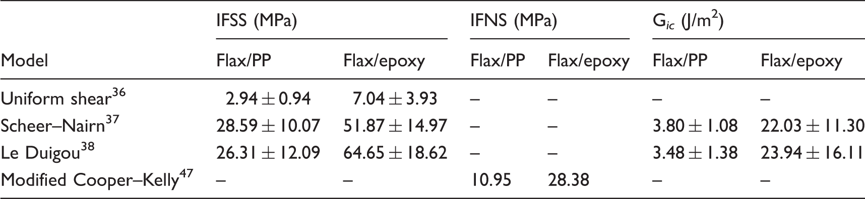
The results from the analysis of microbond tests are listed in Table 6. The IFSS value for flax/PP using the Le Duigou model is 26.31 ± 12.09 MPa, while that for flax/epoxy 64.65 ± 18.62 MPa. For comparison, the mean IFSS values calculated by Le Duigou et al. 38 for a flax/poly(lactic acid) system were in the range of 65–96 MPa.
The transverse tensile strengths for the flax/PP system are 18 MPa and 17 MPa for Vf = 0.22 and Vf = 0.41, respectively. For the flax/epoxy system, they are 39 MPa for both Vf = 0.41 and Vf = 0.51. Interfacial normal strength values calculated using the modified Cooper–Kelly model 47 are 10.95 MPa for flax/PP and 28.38 MPa for flax/epoxy Table 6.
Microbond test simulation
The results from the microbond numerical models are presented in Figure 11. In the initial phase of loading, as yielding of the matrix occurs and the yield zone spreads towards the fibre–matrix contact area (Figure 11(b)), damage is initiated at positions A and B along the interface (Figure 11(a)). On further loading, the damage spreads towards the top and bottom ends of the zone until the contact zone is almost entirely damaged (Figure 11(d)). At this point, the matrix immediately surrounding the zone has completely yielded, debonding has occurred, and stresses in the matrix zone have dropped (Figure 11(e)).
von Mises Stress distribution and damage at the interface for a flax/PP system model. (a) and (b) Damage of the cohesive contact between the fibre and matrix at damage initiation and near debonding, (d) and (e) the corresponding stress states in the matrix (stresses are in MPa).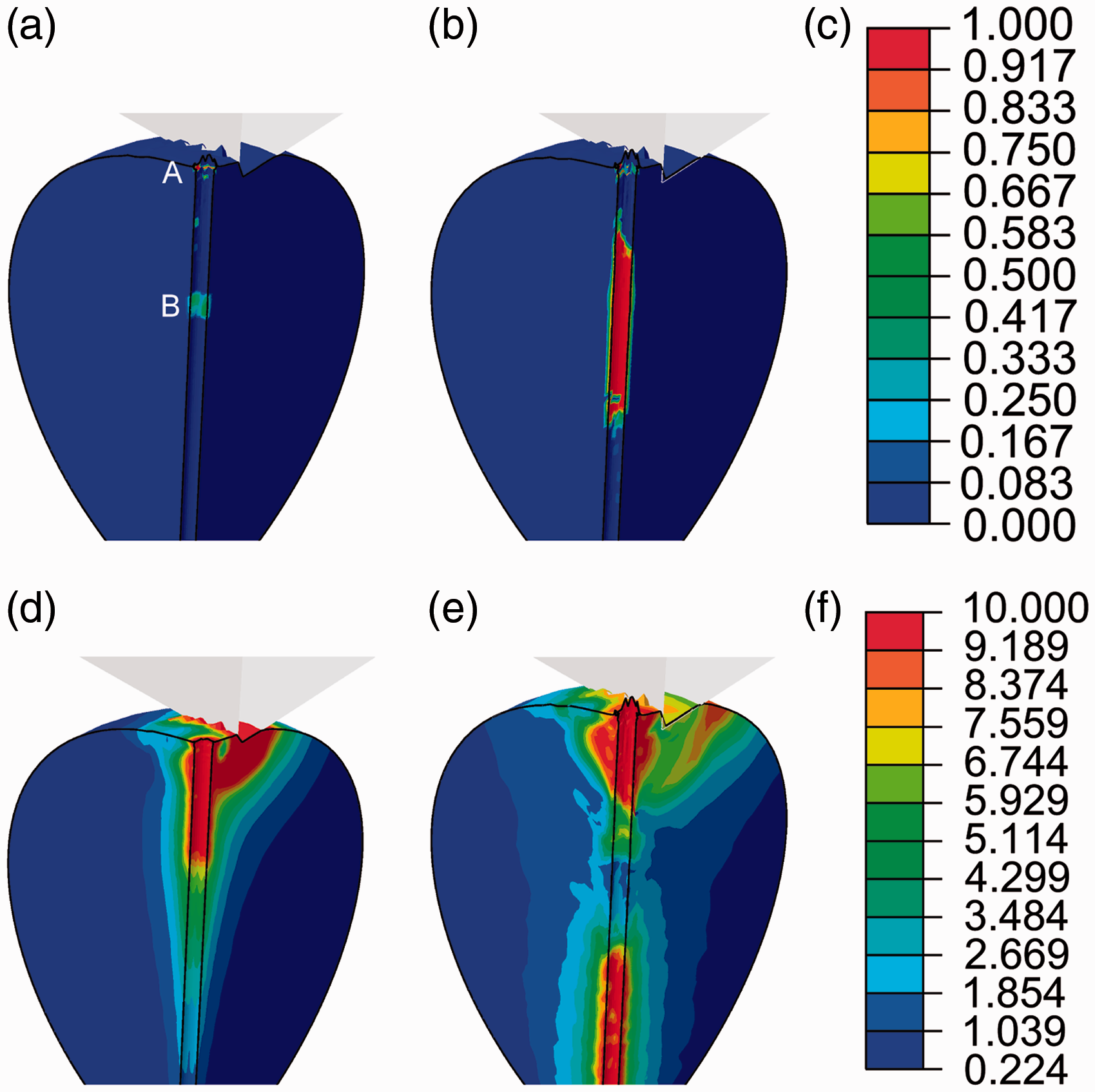
The results obtained from the microbond simulations for the flax/PP and flax/epoxy systems are shown in Figure 12. The results from the experiments have been represented as a region in grey representing the spread in results, to reduce the clutter on the plots.
Load-extension behaviour from microbond finite element model simulations for (a) flax/PP and (b) flax/epoxy systems.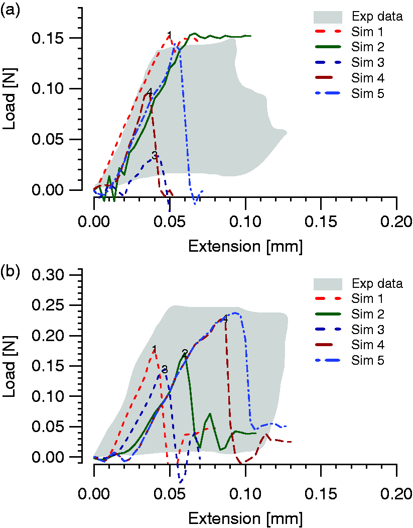
In the flax/PP models, in addition to the parameters listed in Table 7, flax fibre stiffness corresponding to 9° CMF helix angle and IFNS of 10.95 MPa were applied to all models. By increasing the vice angle from 1.26° in Sim 1 to 9.74° in Sim 2, there is no difference in peak load, but only an increase in strain to failure (Figure 12(a)). On further increasing the vice angle to 25.78° in Sim 3 though, there is a 78% drop in peak load prediction from Sim 1 (0.155 N to 0.034 N). In the model, the same IFSS value was used for Sim 2 and Sim 3, but if we were to use a uniform stress assumption, we would have obtained a lower estimate for the failure load. In the Sim 1, Sim 2 and Sim 3, we applied the default contact penalty enforcement method used by ABAQUS for the cohesive surface interaction between the fibre and droplet surface (Figure 5(b)). For Sim 4, the vice angle was returned to 1.26°, and the cohesive stiffness value was estimated by using the linear law.
63
In the case of the flax/epoxy system, the same flax fibre stiffness as in the flax/PP models was used, and the IFSS and IFNS values were applied in a similar manner. As observed in the case of the flax/PP system, increasing the vice angle from 3.35° in Sim 1 to 11.51° in Sim 2 only causes an increase in strain to failure, but increasing it further to 17.38° in Sim 3 causes the load to drop by 18.5% (0.177 N for Sim 1, 0.145 for Sim 3, Figure 12(b)). For Sim 4, with vice angle of 11.51° and default cohesive stiffness constants specified as for flax/PP, the peak load increases to 0.228 N. When the IFSS value was increased by one standard deviation from 51.87 MPa to 66.87 MPa (Sim 5), the peak load increased again to 0.237 N.
Although the microbond test itself is relatively simple to perform, very complex stress states exist in the test system. The failure load recorded for any particular test could depend on a number of factors, including the vice angle, mechanical properties of the interface, mechanical properties of the polymer, fibre diameter and droplet aspect ratio, among others. Depending on the test configuration, failure could initiate due to failure of the interface or that of the polymer. 64 It has been observed that changing the vice angle alone with specimens of the same geometry leads to different peak load values. 65
Here, five different configurations have been used for each material system, varying the vice angle and the properties of the interface. There is considerable overlap between stiffness, peak load and failure strain behaviour between the simulations and the experiments for both the flax/PP and flax/epoxy material systems (Figure 12).
Impregnated yarn failure
Impregnated yarn tests
Shown in Figure 13 are selected results from tests on impregnated flax yarns for both flax/PP and flax/epoxy systems. The result from the numerical model for each system is also shown. The average failure strength of flax/PP impregnated yarns is 24.33 ± 2.18 MPa, with failure occurring at a strain of 0.4 mm/mm. Due to the yielding nature of PP, the stress does not suffer a drastic drop after peak load, and remains around 20–25 MPa (Figure 13(a)). In the case of flax/epoxy impregnated yarns, the failure strength is 70.92 ± 10.67 MPa. However, unlike the flax/PP yarns, since epoxy fails in a brittle manner, the yarns reach peak load, followed by splitting of the specimen into three or more pieces.
Results from tests on impregnated yarns compared to numerical simulations for (a) flax/PP system and (b) flax/epoxy system.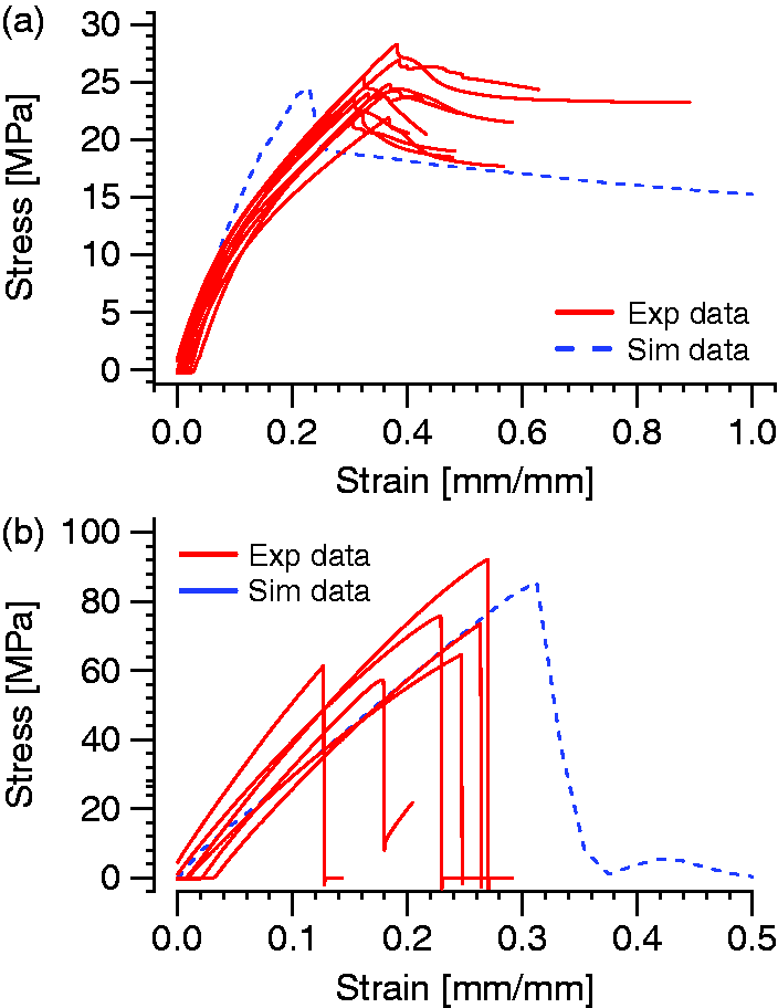
Yarn failure simulation
The peak stress predicted by the flax/PP numerical model is 22.83 MPa, which is only 6.18% lower than the average of the experimental values. The stiffness behaviour, as well as post-yield behaviour is very similar to the experimental values.
The flax/epoxy numerical model was able to predict the stiffness behaviour quite well. However, the failure stress and strain were over-predicted by 20.6% (85.6 MPa simulation v/s 70.92 MPa experimental average) and 27.3% (0.312 simulation v/s 0.245 experimental average), respectively.
Conclusions
A hierarchical framework to obtain composite macro-scale properties from properties on the micro-scale is proposed. In this work, the framework is used to estimate the properties of impregnated yarns from those of the fibres, the matrix material, and the interface between them.
Single flax fibres are considered as analogous to cylindrical composite tubes, and their longitudinal and transverse moduli are estimated by using the CLT theory and varying the microfibril helix angles. From a number of models, one is selected by comparing fibre longitudinal modulus values predicted by the models to values from tensile test data on single fibres. The selected model is then used to estimate flax fibre properties for all numerical models in this study.
The failure in microbond tests is modelled using FE models where the droplet geometry is accounted for, and interface behaviour is described using a traction-separation law between the fibre and matrix surfaces. The values for damage initiation for the law are obtained from the microbond experiments (IFSS) and transverse tensile tests (IFNS). Friction after debonding is defined within the fibre–matrix surface interaction property. The numerical models are able to produce a set of load-extension values that overlap to a large extent with the experimental values. In addition to this, they can also illustrate the effect of varying the vice angle, IFSS and interface strength on the microbond failure load.
Impregnated yarn models with variations in fibre geometry, and hexagonal cross-sections representing the fibres, are generated by sweeping the fibre sections along a helix curve with parameters derived from the actual flax yarn. The fibre, interface and matrix properties are used in these models, to simulate a tensile test. Good agreement with experimental behaviour is observed for both material systems, especially so for flax/PP.
Repeating unit models can be generated from the central fibre-matrix area of the impregnated yarn models to simulate failure in yarns or tows in fabric composites. A link can then be made to macroscale composite part models using yarn-based representations of fabric composites. A multiscale scheme can be constructed, which can enable the prediction of macroscale/structural composite part properties and structural behaviour from the fibre and interface properties obtained in this study.
Footnotes
Acknowledgement
The authors wish to acknowledge the contribution of NeSI high-performance computing facilities to the results of this research.
Declaration of Conflicting Interests
The author(s) declared no potential conflicts of interest with respect to the research, authorship, and/or publication of this article.
Funding
The author(s) disclosed receipt of the following financial support for the research, authorship, and/or publication of this article: The authors would like to thank the Ministry of Business, Innovation and Employment (MBIE) for the financial support through grant no. 3625485 titled ‘Sustainable Composites’ research grant. NZ’s national facilities are provided by the NZ eScience Infrastructure and funded jointly by NeSI’s collaborator institutions and through the Ministry of Business, Innovation & Employment’s Research Infrastructure programme (![]() ).
).