
Abstract
Tubular braided composites are manufactured using a Maypole braiding machine which interlaces yarns in order to manufacture a braided structure. Braids can be produced in Diamond (1/1), Regular (2/2) and Hercules (3/3) patterns. In addition, axial yarns can be included in order to produce triaxial braid structures. Several analytical and finite element analysis models have been developed in order to predict the elastic properties of braided composites. Despite the fact that many models exist for braided composites, a comprehensive model has not been presented that can capture the variety of braiding patterns which can be manufactured using the braiding process. In this study, a new analytical model has been developed that can describe the elastic properties of Diamond, Regular and Hercules braids. The proposed analytical model uses a volume averaging stiffness method in order to account for yarn undulations and the orientation of braid yarns within the braid structure. The model presented here has been compared with the existing FEA and analytical models and has also been validated experimentally. Experimental validation comprised tensile and torsional tests in order to predict the longitudinal and shear moduli for both Diamond and Regular braid geometries. The experimental and proposed model results highlight the effect of braiding pattern and braiding angle on the mechanical properties.
Introduction
Tubular braided composites consist of braided yarns infused in a matrix. Tubular braided composites are fabricated using a Maypole braider or Radial braider and can be manufactured with different braiding patterns. Braiding patterns include: Diamond (1/1), Regular (2/2), Hercules (3/3) and triaxial (Diamond or Regular with axial yarns).1–5 Tubular braided composites can also be manufactured in open and closed mesh configurations.6–10 The different braid patterns and braid configurations allow tubular braided composites to be applied to a wide range of applications.
Braided composites are an attractive manufacturing method over conventional composite laminates due to a high production rate, yarn interlacement and damage tolerance. 11 Due to these factors the use of braided composites is increasing in aerospace, sporting, automotive and marine industries.11–13 Characterization of tubular braided composites is complicated by their non-uniform nature, variable constituents, and variable geometries. The material properties of tubular braided composites are commonly determined experimentally; however, this limits the implementation of tubular braided composite to specific applications. 11
Several models have been developed to predict the mechanical properties of tubular braided composites. The modeling approaches that are currently used for braided composites include: classical laminate plate theory (CLPT)-based models,7,9 finite element models (FEA)13,14 and volume averaging models.11,15–17 Many of the braid models that exist are limited to single braid configurations. For example, the CLPT-based models of Carey and Ayranci are limited to only diamond braided composites and the volume averaging method of Quek et al. is limited to 2D triaxial braids. Several FEA studies have been performed on braided composites where varying braid configurations have been considered;13,14 however, these models are computationally intensive and require specialized training and software to implement. 11 Despite the fact that many analytical, geometrical and finite element models exist for braided composites,7,9,11,13–17 a comprehensive analysis and comparison of the different possible braiding patterns has not been performed. Currently, a generalized analytical model does not exist specifically for tubular composite braids which cover the range of braiding patterns that can be produced using this method.
The aim of this work is to develop a generalized analytical model of tubular braided composites based on the geometrical and mechanical properties of tubular composite braids. A generalized analytical model will provide a powerful tool for the design and implementation of tubular braided composites. In addition, the model will also account for the micromechanical material properties of fiber and resin used to create the braid structure. The proposed model will utilize key braid parameters to provide a powerful design tool for tubular braided composites manufacturers since braids of varying geometry, fiber and matrix can be modeled. Since the material properties of composite braids can be easily predicted using this method this will allow for more widespread implementation of tubular braided composites. The model presented in this manuscript will be validated using data collected from tensile and torsional tests for braid samples produced with Diamond (1/1) and Regular (2/2) braid geometries. The braid samples were produced over a range of braiding angles, 35–55°, in order to investigate the effect of braiding angle on elastic properties. A three-dimensional digital image correlation (3D DIC) measurement technique will be used in order to measure braid sample strain.
Proposed model development
A new generalized model is presented in this paper for describing the mechanical properties of tubular braided composites. The model will be implemented by using micromechanical models to account for matrix and fiber contributions. Geometries of the tubular braid structures will be described using braid equations similar to Alpyildiz et al. 18 The braid equations allow for tubular braided composite to be represented using simple mathematical expressions which can be implemented into solid modeling programs to allow for the visualization and analysis of braid geometries. Finally, a volume averaging method will be used to account for the contribution of the clockwise and counter-clockwise yarns within the braid unit cell.
Micromechanics
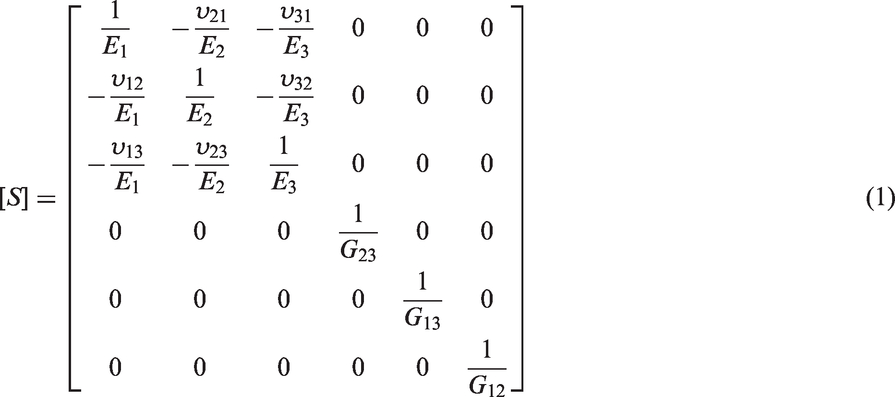
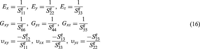
In order to model the mechanical properties of tubular braided composites the mechanical properties of the braid fibers and matrix must be taken into account. The individual braid yarns are assumed to behave as a transversely isotropic material.5,7,9,11,15–17 The compliance matrix, [S], for the braid yarns in the local coordinate system (1-2-3) is shown in equation (1).The stiffness matrix, [C], for the braid yarns in the local coordinate system (1-2-3) can be determined by computing the inverse of the compliance matrix [S] as shown in equation (2). The elastic constants shown in equation 1 were determined using micromechanical models.19,20 The rule of mixtures equations were used to determine the longitudinal elastic modulus E1 and major Poisson’s ratio, ν12. The Halpin-Tsai equations were used to determine the transverse elastic modulus E2 and in-plane shear modulus G12.
20
Finally, semi-empirical models were used to determine the out-of-plane shear modulus G23 and out-of-plane shear modulus ν23.
9
Since the yarns are assumed to be transversely isotropic E2 = E3 and G12 = G13.19,20

Braided composite geometry
The tubular braided composite geometry will be described using equations that take into account key braiding parameters such as braid angle (θ), yarn width (Wy), yarn thickness (a), mandrel diameter (D0), and the number of braider bobbins (N). Example braid geometries for Diamond (1/1) and Regular (2/2) braided composites are shown in Figure 1. The fully parametric braid geometries shown in this figure were generated using a custom Python script and a computer aided design software package (Rhinoceros 3D 5.0, Robert McNeel & Associates, Seattle, WA, USA) to visualize the three dimensional braid geometries.
Example braided composite geometries: (a) diamond braid (1/1) and (b) regular braid (2/2).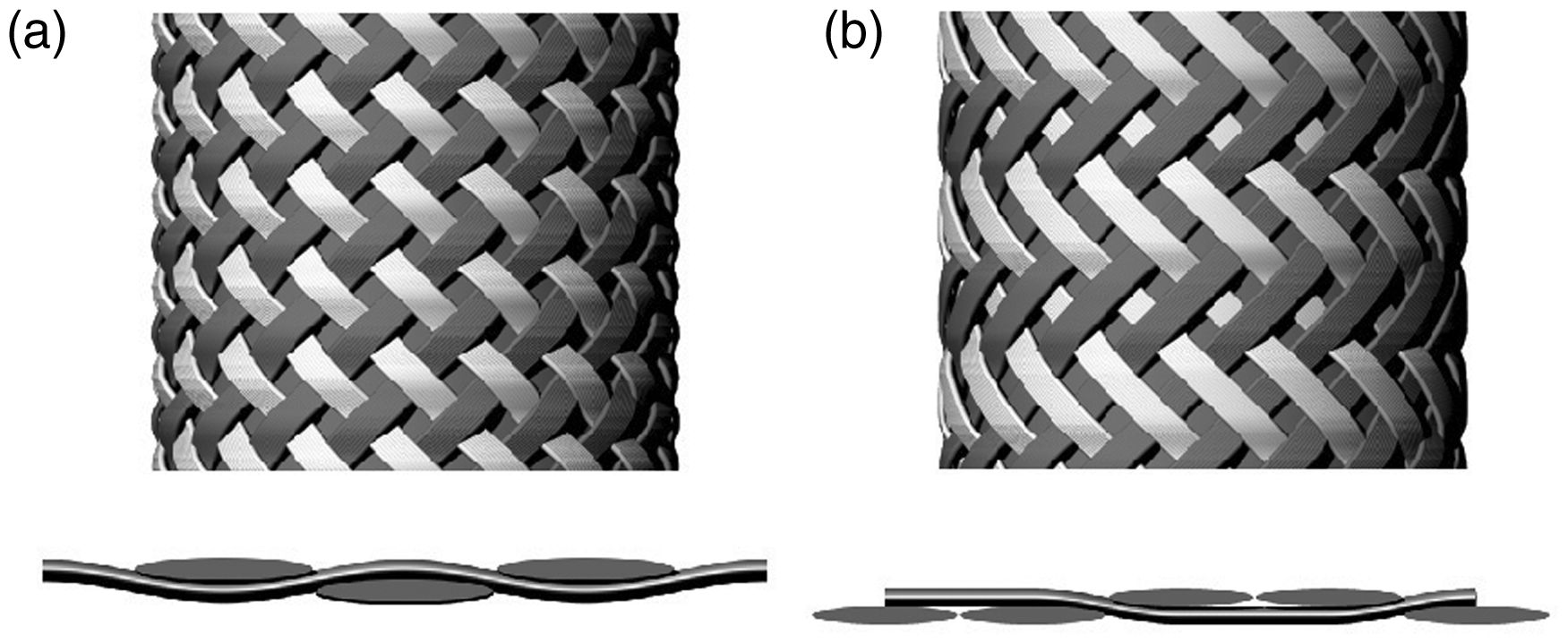
The undulation length of braid yarns within a unit cell was determined based on the number of braider yarns (N), braid nominal radius (r0 = D0/2) and braid angle (θ). The relationship between braid yarn shift angle (β) and undulation length is illustrated in Figure 2. The braid shift angle, β, shown in Figure 2 is related to half the total number of yarn carriers ( Braid unit cell geometry.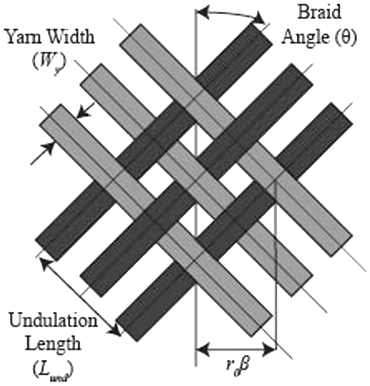


In order to model the mechanical behavior of braided composites, two coordinate system transformations are required. These coordinate system transformations are computed using geometric parameters of the composite braids. The coordinate system transformation in Figure 3(a) is required in order to account for the undulation of the braid yarns and depends on the crimp angle (φ) of the braid yarns. The coordinate system transformation in Figure 3(b) accounts for the braid angle (θ) of the clock-wise and counter-clockwise yarns.
Coordinate system transformations: (a) conversion from yarn coordinate system (1-2-3) to undulation coordinate system (x′-y′-z′) and (b) Conversion of undulation coordinate system (x′-y′-z′) to global coordinate system (X-Y-Z).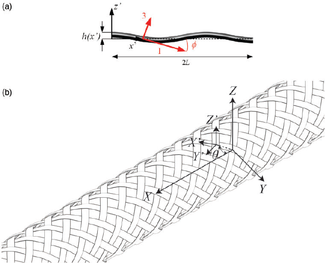
The braid yarns were assumed to follow a sinusoidal path due to the repeating nature of the braiding process.5,18,21,22 The equations for the braid yarns will be described in their local coordinate system (x′-y′-z′). This coordinate system is required since a coordinate system transformation will be required for the volume averaging method described in Volume averaging section.
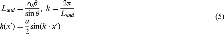
The equation for a diamond braided composite is shown in equation (5). In this equation, Lund represents the length of one undulation of a braid yarn. The variable k represents the braid yarn period and the variable a represents the thickness of the braid yarn. The undulation height of the braid yarn is represented by the variable h(x′) and the position along the undulation length is represented using the variable x′.
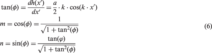
In addition, the crimp angle of the braid yarns (φ) was determined along the braid yarn length. The braid yarn crimp angle was determined by computing the derivative of the braid yarn undulation height equation (h(x′)). Determination of the braid yarn crimp angle is shown in equation (6). The braid yarn crimp angle is necessary for accounting for the effect of yarn undulations of braid mechanical properties.
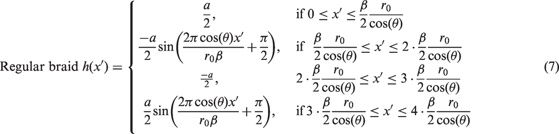
Equations for Regular braids were determined using similar equation to the sinusoidal Diamond braid equation shown in equation (5). Equations for the undulation height of Regular braids are shown in equation (7). The difference between Diamond and Regular is demonstrated in equation (7). This equation shows that Regular braids are described by a piece-wise function. Equation (7) divides the Regular braid yarn path into undulating and non-undulating regions. The yarn crimp angle for Regular braid was computed in a similar manner to the diamond braid shown in equation (6). The undulation of the Diamond and Regular braid patterns are compared in Figure 4.
A comparison of diamond (1/1) and regular (2/2) braid yarn undulations in the undulation coordinate system (x′-y′-z′).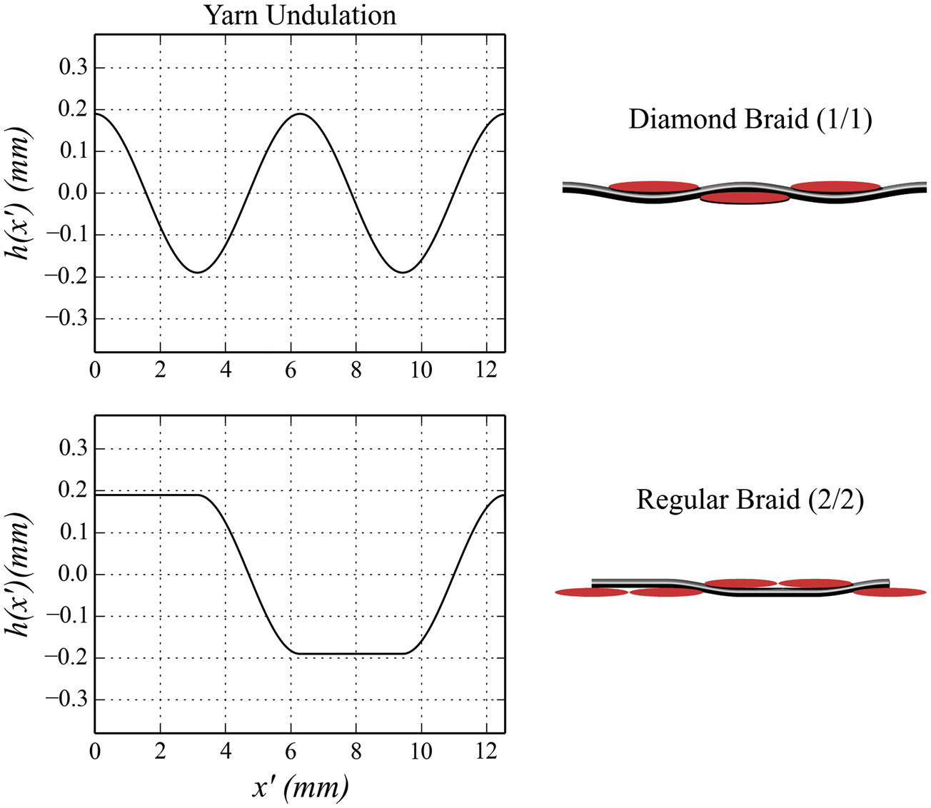
Volume averaging
A volume averaging stiffness method has been utilized in order to determine the material properties of tubular braided composites.23–25 This method was selected since it allows for the mechanical properties of the wide variety of braid geometries shown in Braided composite geometry section to be determined. The volume averaging stiffness method has been previously used to model the behavior of 2D triaxial braided composites;11,15–17 however, this method has not been generalized to account for the braid geometries shown in Braided composite geometry section.
The volume averaging method involves three main steps. First, a coordinate system transformation is performed to convert from the local yarn coordinate system (1-2-3) to the undulation coordinate system (x′-y′-z′). The local to undulation coordinate system transformation is illustrated in Figure 3(a). This figure shows that the braid crimp angle, φ, is used to transform from the local coordinate system to the undulation coordinate system.
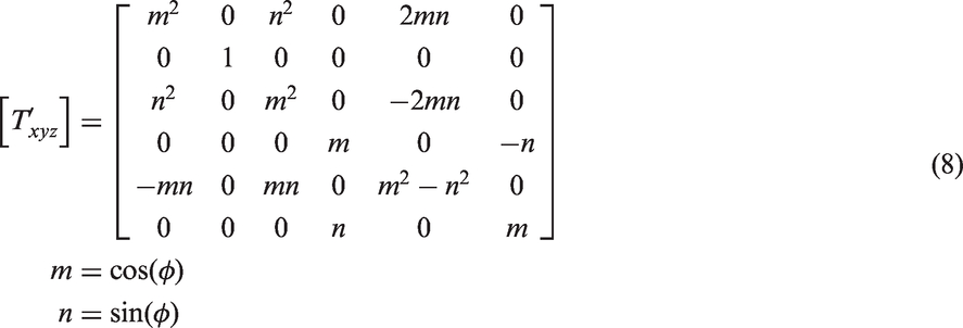
Two approaches have been used to account for braid yarn undulations. The first approach by Byun determined the effective compliance matrix [S′xyz] for the undulating braid yarns. 11 The transformation matrix used to convert from the local (1-2-3) coordinate system to the undulation (x′-y′-z′) coordinate system is shown in equation (8). The yarn crimp angle (φ) is determined by calculating the derivative of the braid yarn equations (5) and (7) shown in Braided composite geometry section. The compliance matrix [S′xyz], shown in equation (9), in the undulation coordinate system is calculated by integrating over the yarn undulation length. The second approach by Quek et al. determines the effective stiffness matrix [C′xyz] of the undulating yarns. 16 The calculation of the effective yarn stiffness is shown in equation (1). The two methods used to determine the effective mechanical properties of the undulating yarns will be utilized in this manuscript. The study by Quek et al. found significant differences between predicted and measured shear moduli when using the effective stiffness calculation shown in equation (10). The discrepancy between measured and predicted shear moduli has been highlighted by Shokrieh and Mazloomi. 17
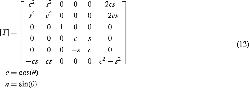
The second step in the volume averaging method is illustrated in Figure 3(b) where a second coordinate system transformation is performed to convert from the undulation coordinate system (x′-y′-z′) to the global coordinate system (X-Y-Z). The transformation matrix [T] to convert from the undulation to global coordinate system is shown in equation (12). In this equation, the braid angle (θ) is used determine the stiffness matrix, [CXYZ], of each braid yarn in the global coordinate system. The calculation of the stiffness matrix [CXYZ] is shown in equation (13).


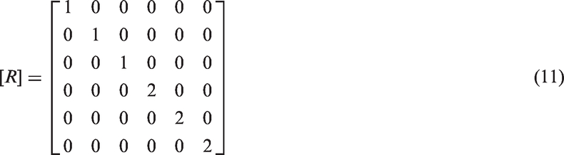

The final step in the volume averaging procedure accounts for the contributions of the clockwise and counter-clockwise braid yarns and, if present, axial yarns. The volume averaging equations for Diamond and Regular braid yarns are illustrated in section Braided composite geometry. The volume averaging method accounts for the contribution of the clockwise (θ+) and counter-clockwise (θ−) braid yarns. In addition, matrix-only regions and axial yarns can also be accounted for. The final overall stiffness matrix [CG] for the braided composite is determined by computing the volume fraction of the clockwise (Vfθ+), counter-clockwise (Vfθ-) and excess matrix (Vm) within the braid unit cell. The equation for the overall stiffness matrix [CG] is shown in equation (14). In equation (14), the stiffness matrices for the clockwise and counter-clockwise braid yarns are


The prediction of the elastic constants of tubular braided composites was automated by creating a custom program (MATLAB, 2016b, The Math Works, Natick, MA) that automates the above volume averaging and geometrical analysis procedure. Using this method the effect of braid geometry or matrix and fiber material properties can be rapidly explored and can therefore be used as a design tool for manufacture tubular braided composites.
Model predictions and discussion
Geometric measurements of the test specimen.
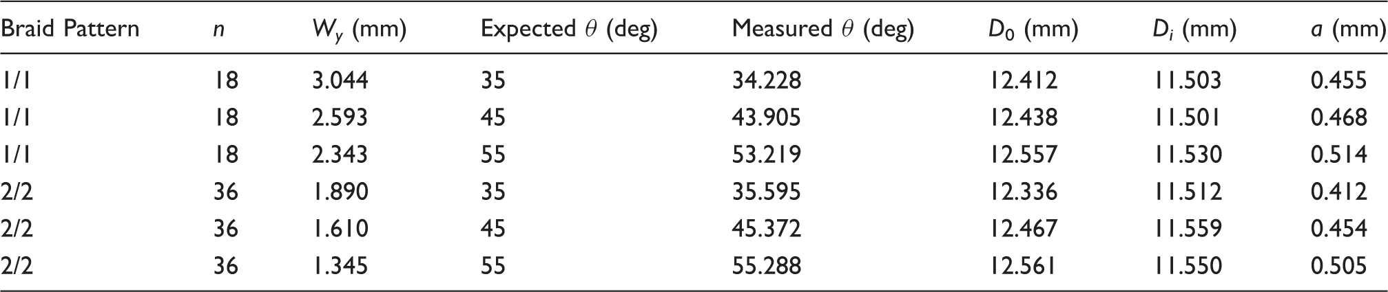
Note: All braid samples were manufactured with 36 bobbins. Twenty braid samples were manufactured for each braid pattern and braid angle combination.
n: number of yarns; Wy: yarn width (mm); θ: measured braid angle (deg); D0: outer diameter (mm); Di: inner diameter (mm); a: yarn thickness (mm).
Example model predictions
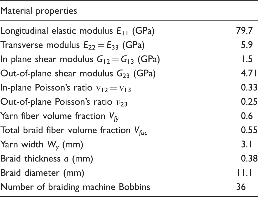
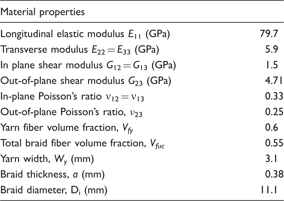
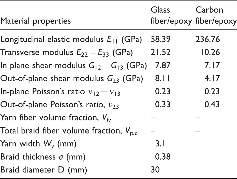
Yarn mechanical and geometric properties for a Diamond (1/1) and Regular (2/2) braided composite.
Representative results comparing the elastic modulus of a Diamond and Regular braid are shown in Figure 5. This figure shows the effect of braiding pattern on the elastic constants for braids produced with equivalent fiber volume fractions. Figure 5 demonstrates that the proposed model predicts that Diamond and Regular braids will have similar Longitudinal (Exx) and Transverse (Eyy) modulus while there are differences in the Shear moduli (Gxy) as can be seen in Figure 5(c). The similar Longitudinal (Exx) and Transverse (Eyy) moduli observed are due to the equivalent fiber volume fractions for both braiding geometries. The small differences in elastic properties between the Diamond and Regular braids are due to the undulation of the braid yarns, as demonstrated in Figures 1 and 4. The difference in the mechanical properties can be attributed to the effect of the crimp angle (φ) of the braid yarns, also demonstrated in Figure 4. In this figure, it can be seen that fiber undulations are limited to specific regions for the Regular braids whereas undulation occur throughout the diamond braid strand path. Since the fiber undulations are more limited for Regular braids than Diamond braids, this results in a greater contribution of the braid yarns to the in-plane elastic properties (Exx and Eyy) of the Regular compared to the Diamond braid pattern. Similarly, the shear moduli of the Diamond and Regular braids are compared in Figure 5(c). The shear modulus for the two braid geometries is not symmetric about 45° as is commonly predicted for braided composites.
8
The asymmetry shown in Figure 5 is due to several factors: the effect of braid angle (θ) on cover factor and the crimp (φ) of the braid yarns. Both the braid cover factor and yarn crimp are a function of braid angle. This figure demonstrates that the Diamond braids exhibit a higher shear modulus (Gxy) than the Regular braid pattern. The model results shown in Figure 5 demonstrate the ability of the proposed model to allow for direct comparison between different braiding patterns.
A comparison of diamond (1/1) and regular (2/2) elastic moduli for braid manufactured using 36 bobbins, a mandrel diameter of 11.1 mm and a yarn width of 3.1 mm: (a) longitudinal elastic modulus (Exx), (b) transverse elastic moduli (Eyy) and (c) shear modulus (Gxy).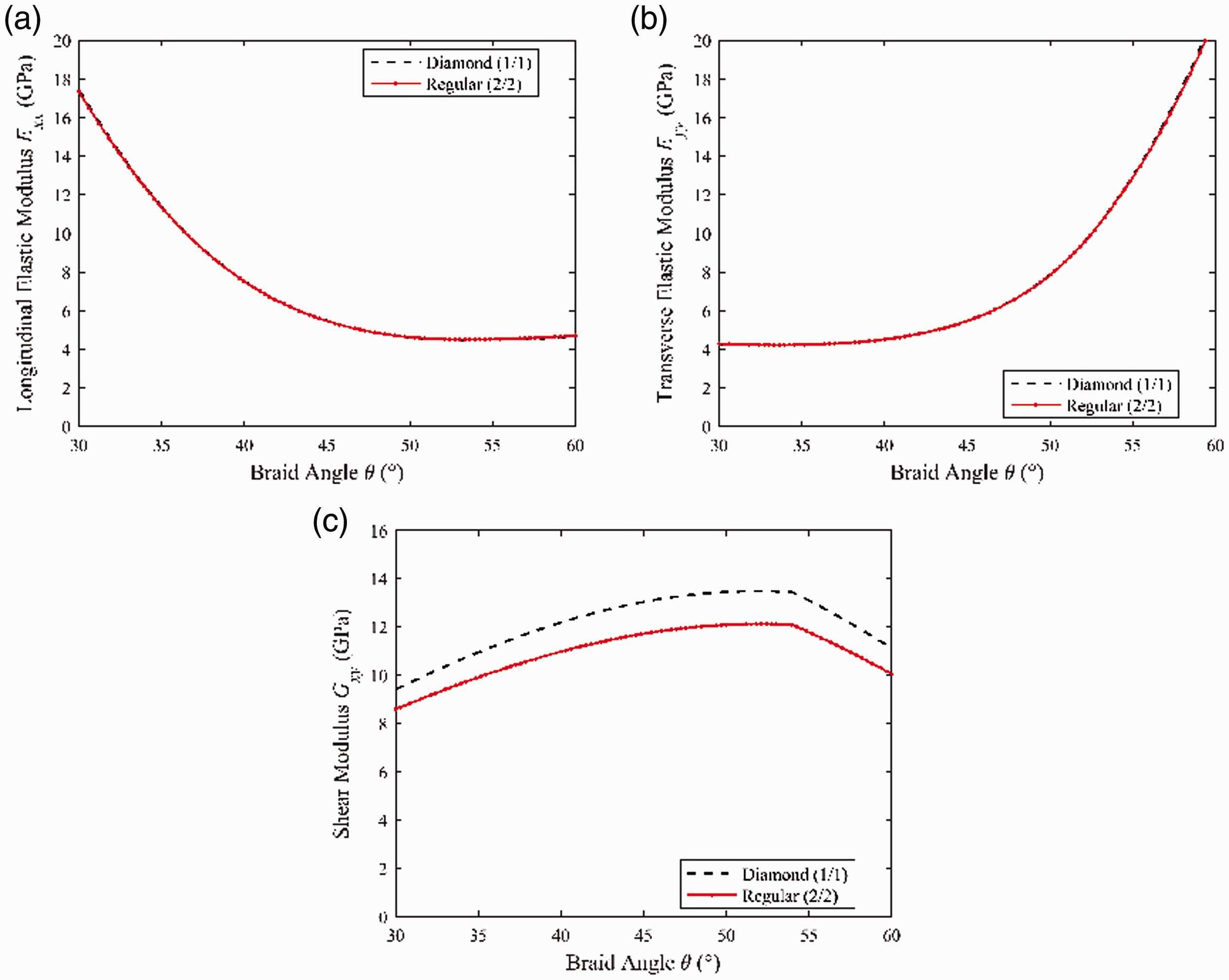
A comparison with the existing models
The braid model developed here was also compared with the results of existing models which exist in literature. Several analytical and finite element analysis (FEA) models exist for braided composites; however, many of these models are limited to only one braid configuration, i.e. Regular braids, Diamond Braids or Triaxial braids.7,9,13–17,27,28 One limitation of the existing studies is that some or all of the critical parameters for manufacturing braided structures including: braid diameter (D0), number of bobbins used to produce the braid structure (N), yarn width (Wy) and yarn thickness (a) are neglected. These parameters are necessary in order to produce comparable braid structures. The motivation behind the model presented here is to allow for various braid configurations to be modeled and for designers to be able produce braids with known material properties using input parameters from the braid manufacturing process.
The study by Ayranci and Carey developed a curved unit cell model based on CLPT theory in order to predict the mechanical properties of tubular braided composites. 7 The model of Ayranci and Carey is exclusively able to predict the mechanical properties of Diamond (1/1) braided composites. The model of Ayranci and Carey stated braid yarn dimensions (Wy and a) but the number of yarns (N) used to produce the braid structure were not stated.
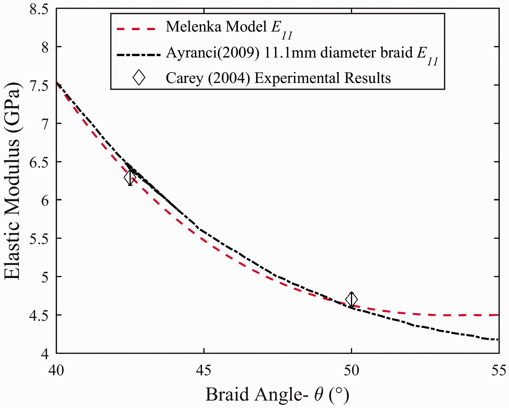
A comparison between the proposed model and the CLPT-based model of Ayranci and Carey is shown in Figure 6. The yarn mechanical properties used for this comparison are summarized in Table 3. This table shows that both models predict a decrease in longitudinal elastic modulus as braid angle increases. The model of Ayranci and Carey assumes that yarn undulation only occurs within defined regions within the braid unit cell.7,9 Braid yarns are assumed to be flat in the cross-over regions (where clockwise and counter-clockwise yarns overlap). This assumption will result in an over-prediction of the longitudinal elastic modulus of a diamond braid since the braid yarn crimp angle is neglected in the cross-over regions. The crimp or undulation of Diamond braids is illustrated in Figure 4. This assumption results in a greater contribution of the braid yarns in the longitudinal direction in the cross-over regions. The braid models of Ayranci and Carey also assumes that the braid unit cell geometry will exhibit symmetrical behavior as a function of braid angle (θ). This means that the braid unit cell height and width will vary proportionally as a braid angle changes. This assumption is not physically possible since the braid unit cell width (WunitCell) is a constant value that will depend on the braid mandrel radius (r0) and the number of braid yarns (n) used to fabricate the braid geometry. The relationship between mandrel diameter, number of braider yarns and braid angle are described by equations (3) and (5).
A comparison of the proposed model results with the CLPT-based model results of Ayranci and Carey.
7
Yarn mechanical and geometric properties for a Diamond (1/1) braided composite examined by Ayranci and Carey
7
Experimentally determined shear moduli by Ayranci and Carey. 8

A comparison of experimentally determined and the proposed model shear moduli.
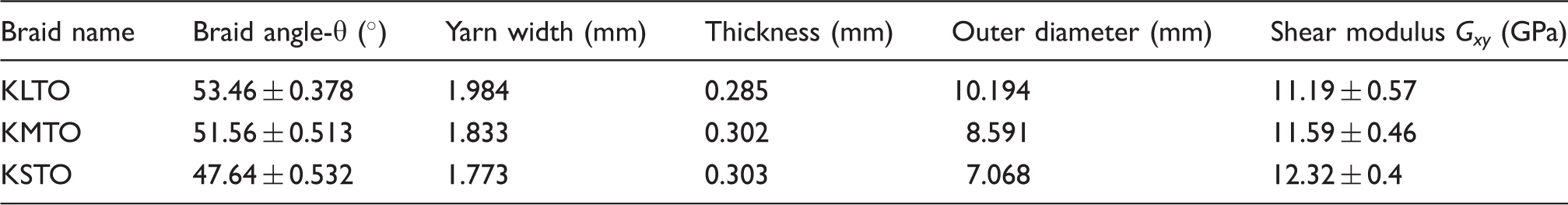
Yarn mechanical and geometric properties for a Regular (2/2) braided composite examined by Ji et al. 13
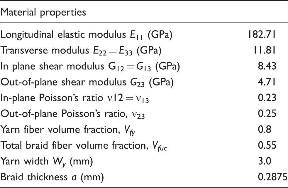
A comparison between the proposed model and FEA model of Ji et al. results can be seen in Figure 8. This figure shows good agreement between the two model results. Both models exhibit a decreasing longitudinal elastic modulus with braid angle and increasing transverse elastic modulus with braid angle. Both models also exhibit an asymmetric relationship between the longitudinal and transverse elastic moduli.
A comparison between the proposed model results and the model results of Ji et al.
13
The longitudinal (E11), transverse (E22) and out-of-plane (E33) elastic moduli are compared.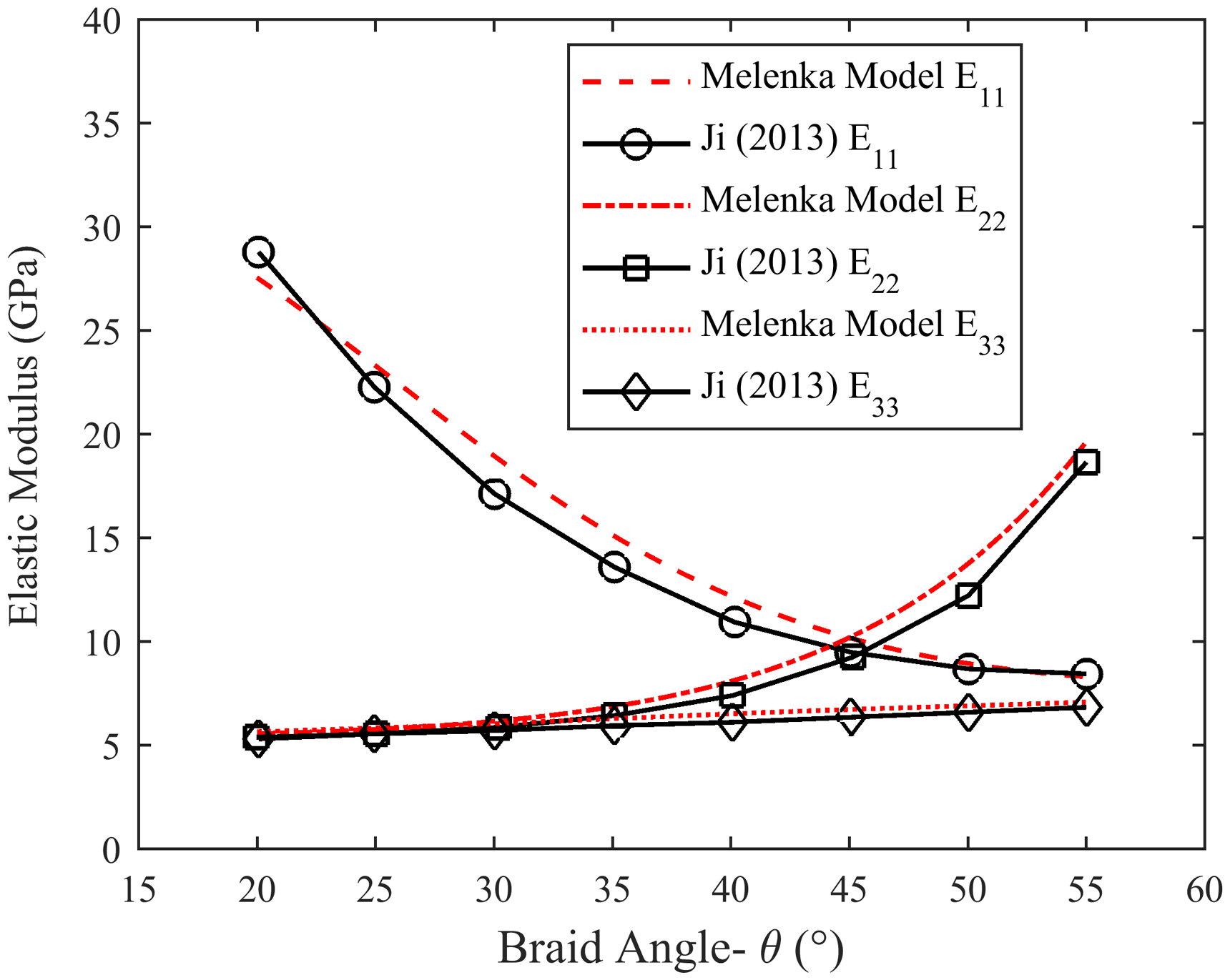
The FEA model of Xu et al. analyzed the mechanical properties of Diamond (1/1), Regular (2/2) and Hercules (3/3) braids. 14 The model presented by Xu et al. is consistent with other braided composite models in that this model predicts decreasing longitudinal elastic modulus with braid angle and an increasing transverse elastic modulus with braid angle. The model by Xu et al. does not demonstrate asymmetrical behavior between longitudinal and transverse elastic modulus as seen by Ji et al. The symmetry demonstrated in the model by Xu et al. is due to the unit cell geometry used to describe the different braid geometries. The unit cell geometry described by Xu et al. varies proportionally with the braid angle similar to the model of Ayranci and Carey.
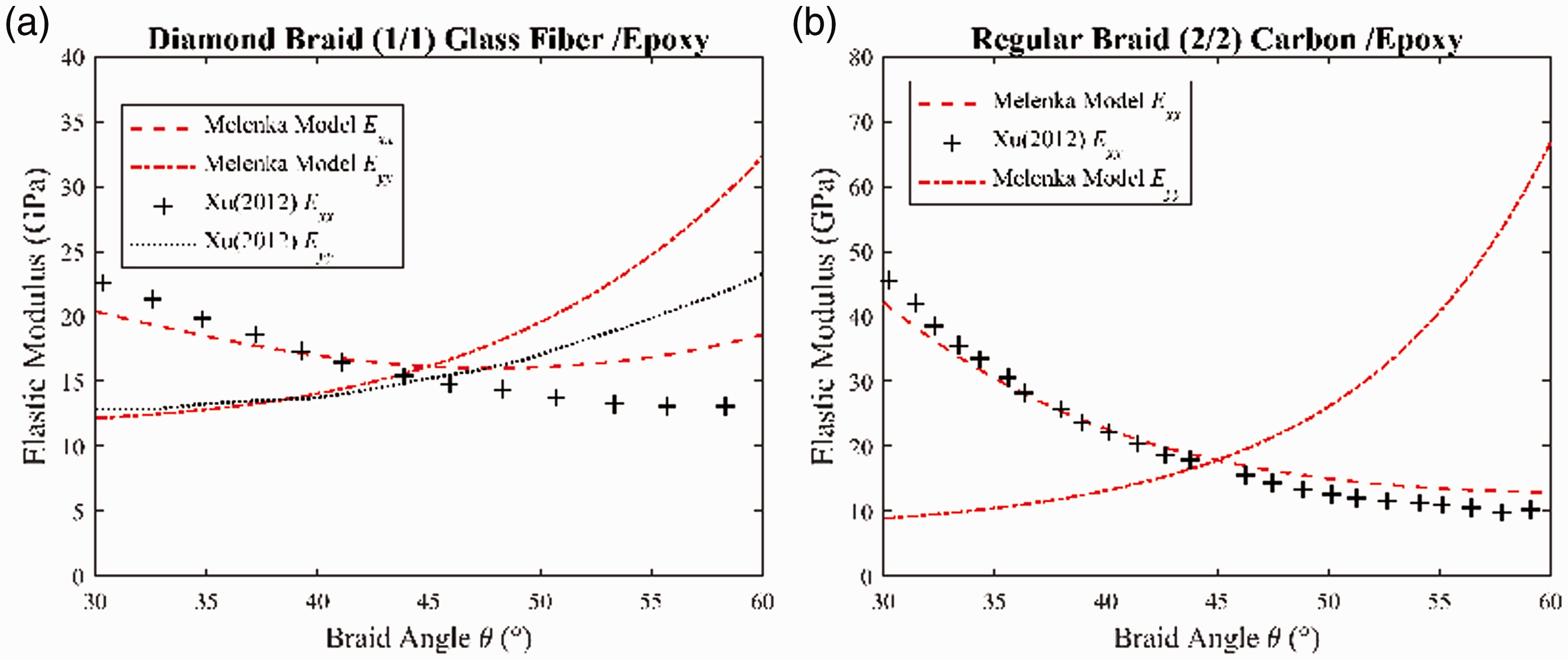
The proposed model and the FEA model of Xu et al. are compared in Figure 9. The yarn mechanical properties used for this comparison are summarized in Table 6. The study by Xu et al. used Glass Fiber/Epoxy for Diamond braids and Carbon Fiber/Epoxy for Regular braids. Subtle differences exist between the proposed model and FEA model of Xu et al. In particular, the model of Xu et al. does not exhibit an asymmetric relationship for the longitudinal and transverse elastic moduli about 45°. The lack of asymmetry in the Xu model results in deviation between the proposed model and the model results of Xu et al., in particular for elastic modulus results above 45°.
A comparison of the proposed model results and the model results of Xu et al.
14
(a) A comparison of diamond (1/1) braid results for a glass fiber/epoxy braid. (b) A comparison of regular (2/2) braid results for a carbon fiber/epoxy braid. Yarn mechanical properties and geometry for a Diamond (1/1) and Regular (2/2) braided composite examined by Xu et al.
14
Experimental model validation
In order to validate the model presented in this manuscript, a series of mechanical tests were performed to compare model predictions with experimental results. To experimentally analyze tubular braided composites three braid angles were evaluated (35, 45 and 55°) and two braid patterns were used (Diamond and Regular). All braids were manufactured using the same number of braider bobbins and manufactured with the same braid mandrel diameter. The braid samples were tested in both tension and torsion which allows for the longitudinal elastic modulus and shear modulus to be determined. The complete experimental methodology is described by Melenka 29 All braid samples were evaluated using a three-dimensional digital image correlation technique in order to measure full-field strain of each braid sample.
Longitudinal elastic modulus
The representative strain fields for a Diamond (1/1) and Regular (2/2) braid are shown in Figure 10. A total of 10 samples were evaluated for each braid angle which resulted in a total of 60 tests. Strain fields like the ones shown in Figure 10 were used to evaluate the stress–strain behavior of each braid sample. The resulting average elastic moduli and standard deviation for each braid angle and braid type are summarized in Figure 11. Figure 11 shows a decrease in longitudinal elastic modulus with an increase in braid angle.
Representative strain fields generated from images collected during tensile tests: (a) diamond braid (1/1) 35° braid angle (b) regular braid (2/2) 35° braid angle. A comparison of experimentally determined longitudinal elastic modulus of diamond (1/1) and regular (2/2) braids.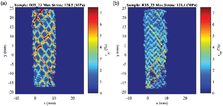
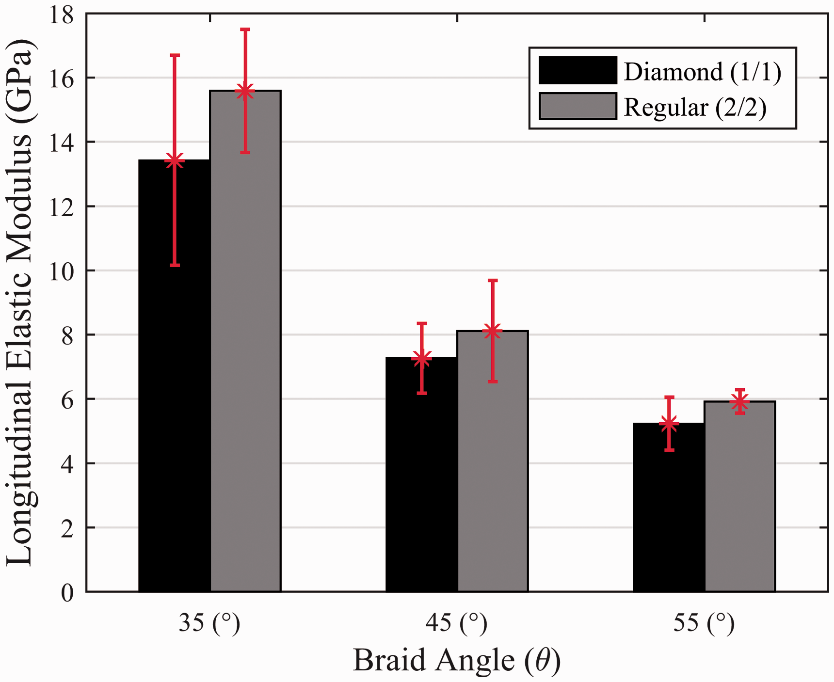
The experimental and predicted results for both the Diamond and Regular braid geometries are compared in Figure 12. This figure shows that the proposed braid model and experimental results both predict that increasing braid angle results in a decrease in longitudinal elastic modulus for both Diamond and Regular braids. Figures 11 and 12 also show that Regular braids manufactured with the same number of braider bobbins and braid yarn Denier result in greater longitudinal elastic moduli than Diamond braids for braids of the same braid angle.
A comparison of longitudinal elastic modulus experimental results with the proposed model results: (a) diamond braid (1/1) and (b) regular braid (2/2).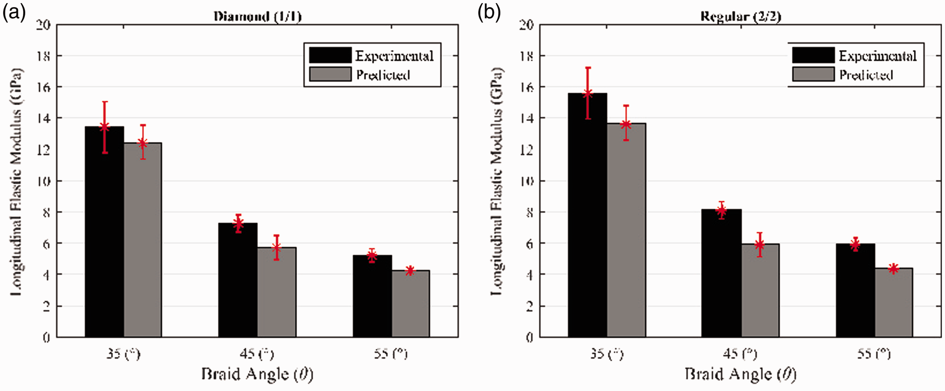
Shear modulus
The shear moduli of Diamond and Regular braids were examined in a similar way to the longitudinal elastic moduli as shown in the Longitudinal elastic modulus section. The representative shear strain fields for both Diamond and Regular braids are shown in Figure 13. In addition, the resulting shear moduli for the experimentally measured braid samples are compared in Figure 14.
Representative shear strain fields generated from images collected during torsion tests: (a) diamond braid (1/1) 35° braid angle and (b) regular braid (2/2) 35° braid angle. A comparison of experimentally determined shear modulus of diamond (1/1) and regular (2/2) braids.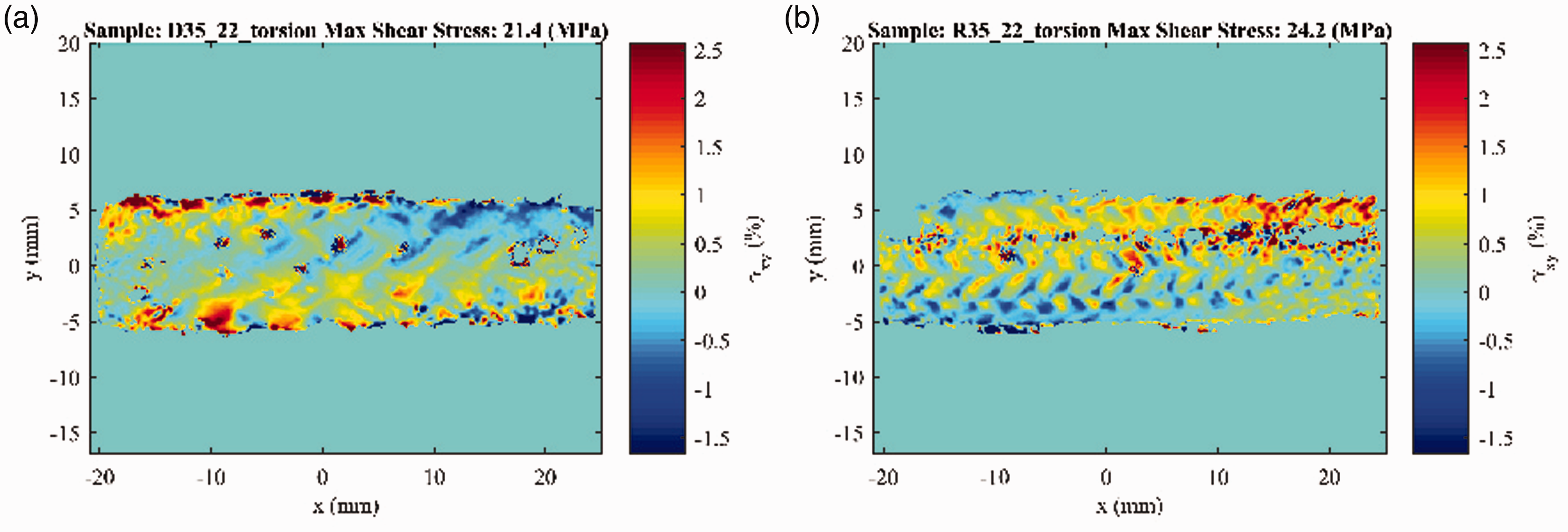
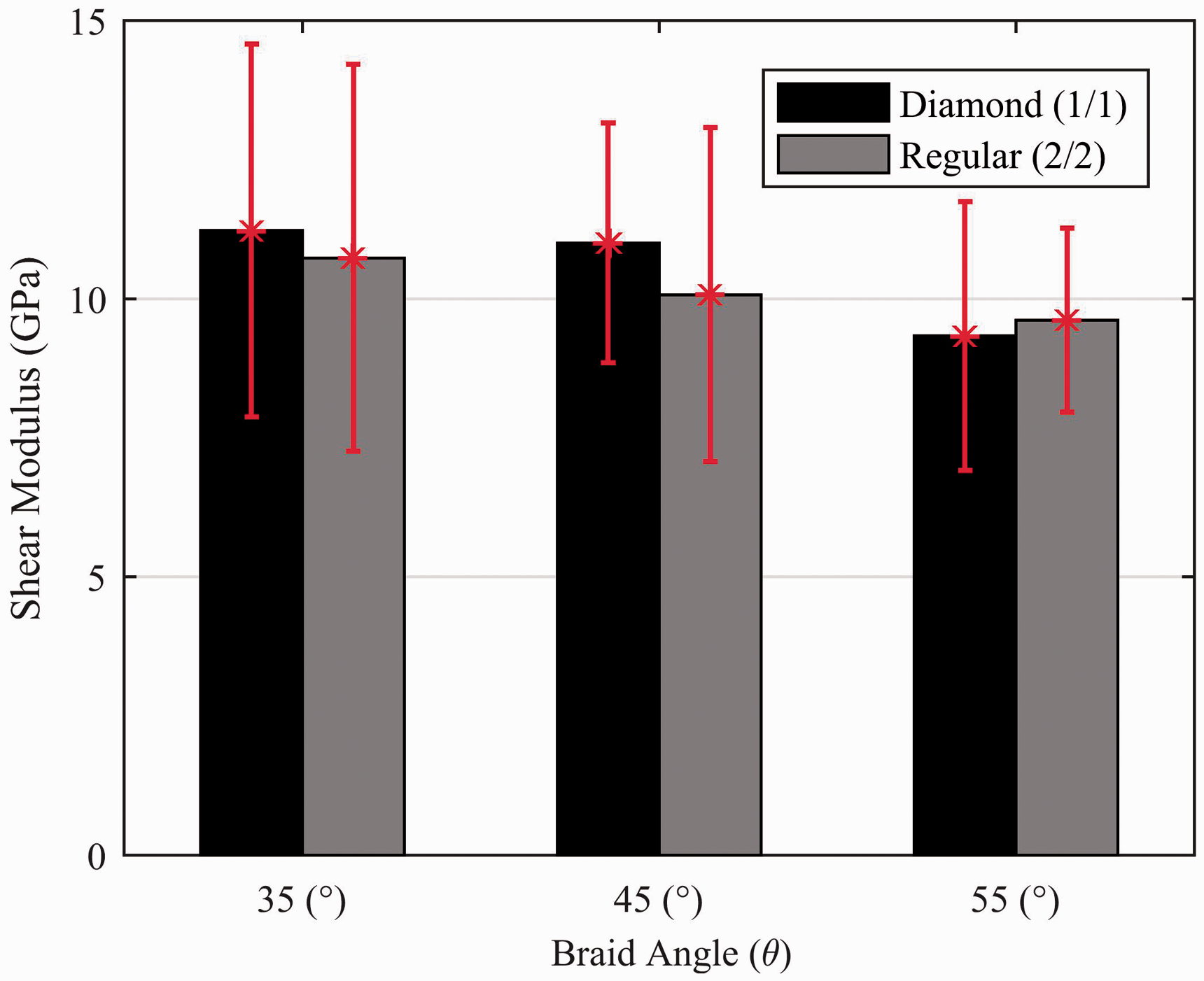
The experimental and model results for the Diamond and Regular braids are compared in Figure 15. Figure 15 shows that there is a decrease in shear modulus with an increase in braid angle. The Diamond braid shear moduli were determined to be 11.22 ± 3.34, 11.00 ± 2.156 and 9.32 ± 2.41 GPa for braids manufactured with braid angles of 35, 45 and 55° respectively. Similarly, the Regular braid shear moduli were determined to be 10.73 ± 3.47, 10.73 ± 3.00 and 9.61±1.65 for braid angles of 35, 45 and 55° respectively. The results in Figure 14 demonstrate that there is significant variation in shear modulus results for both the Diamond and Regular braids.
The effect of braid angle variation on shear modulus: (a) diamond braid (1/1) and (b) regular braid (2/2).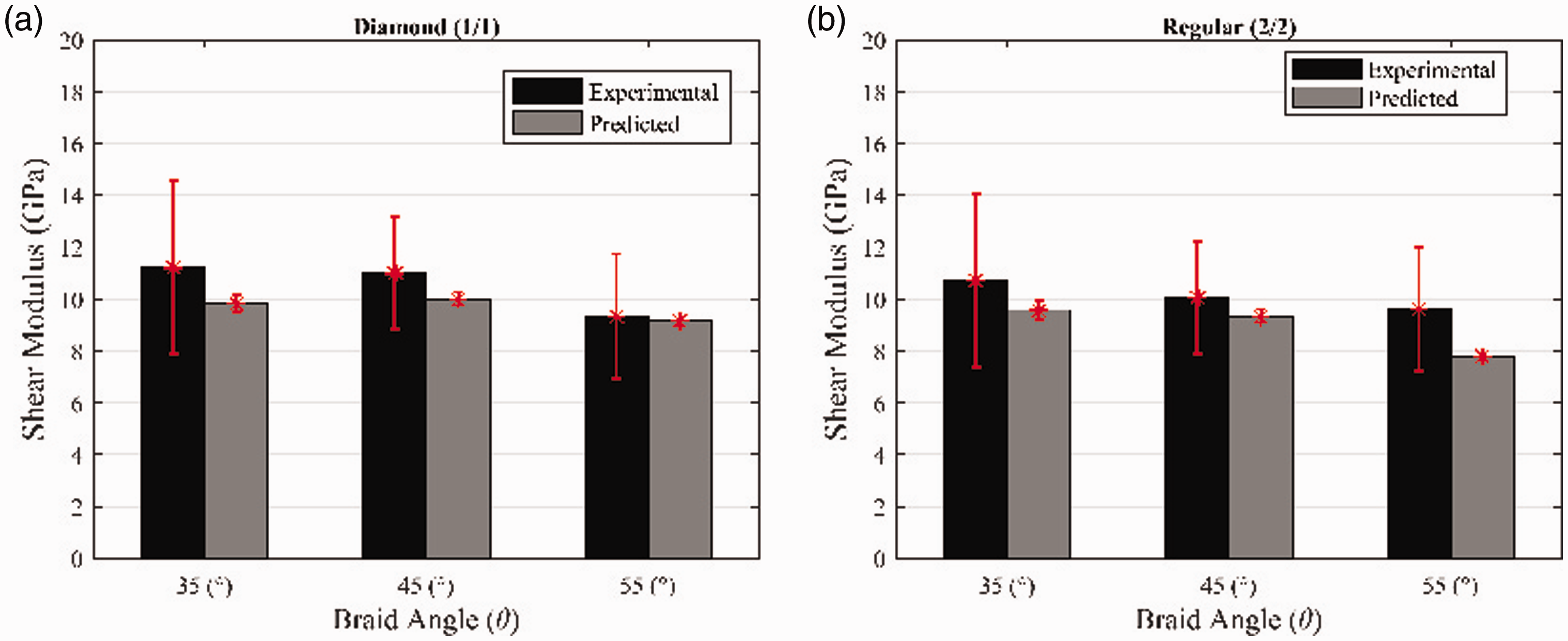
The experimental results for the Diamond and Regular braids were compared with the proposed model results. A comparison of the predicted and experimental results can be seen in Figure 15. This figure shows that there is agreement between the predicted and experimentally determined shear moduli for both the Diamond and Regular braid configurations. The shear modulus for the Diamond and Regular braids was determined by computing the average of resulting shear moduli using equations (9) and (10). Using equation (9) to compute the effective mechanical properties of the composite braids provides a lower bound for the shear modulus while using equation (10) provides an upper bound for the shear modulus. Using the average shear modulus by using a combination of equations (9) and (10) provided agreement between the shear moduli for both the Diamond and Regular braids as can be seen in Figure 15. Similar bounding techniques are used for estimating shear moduli as demonstrated by Jones. 20
Previous studies that have examined the in-plane shear modulus of braided composites have demonstrated that experimental and model results can result in significant differences. For example, the study by Quek et al. found that model predictions and experimental results for the in-plane shear modulus varied by 27%.16,17 A better agreement between the model and the experimental results was achieved by Shokrieh and Mazloomi where the model and the experimental results differed by 6.92%. It has been suggested that using a combination of iso-stress and iso-strain assumptions may result in a better agreement with experiments. 27 The model presented in this manuscript uses a combination of iso-stress and iso-strain conditions in order to predict in-plane shear modulus for braided composites. The results in Figure 15 demonstrate an agreement between experimental and model results for in-plane shear modulus.
Additional model applications
The braid model presented herein can also be applied to Hercules (3/3) braids. The undulations of Hercules braids can be described using an equation in a similar manner to Regular braids as shown in equation (17). The equation to describe the geometry of the Hercules braid is based on the geometric equations of Alpyildiz.
18
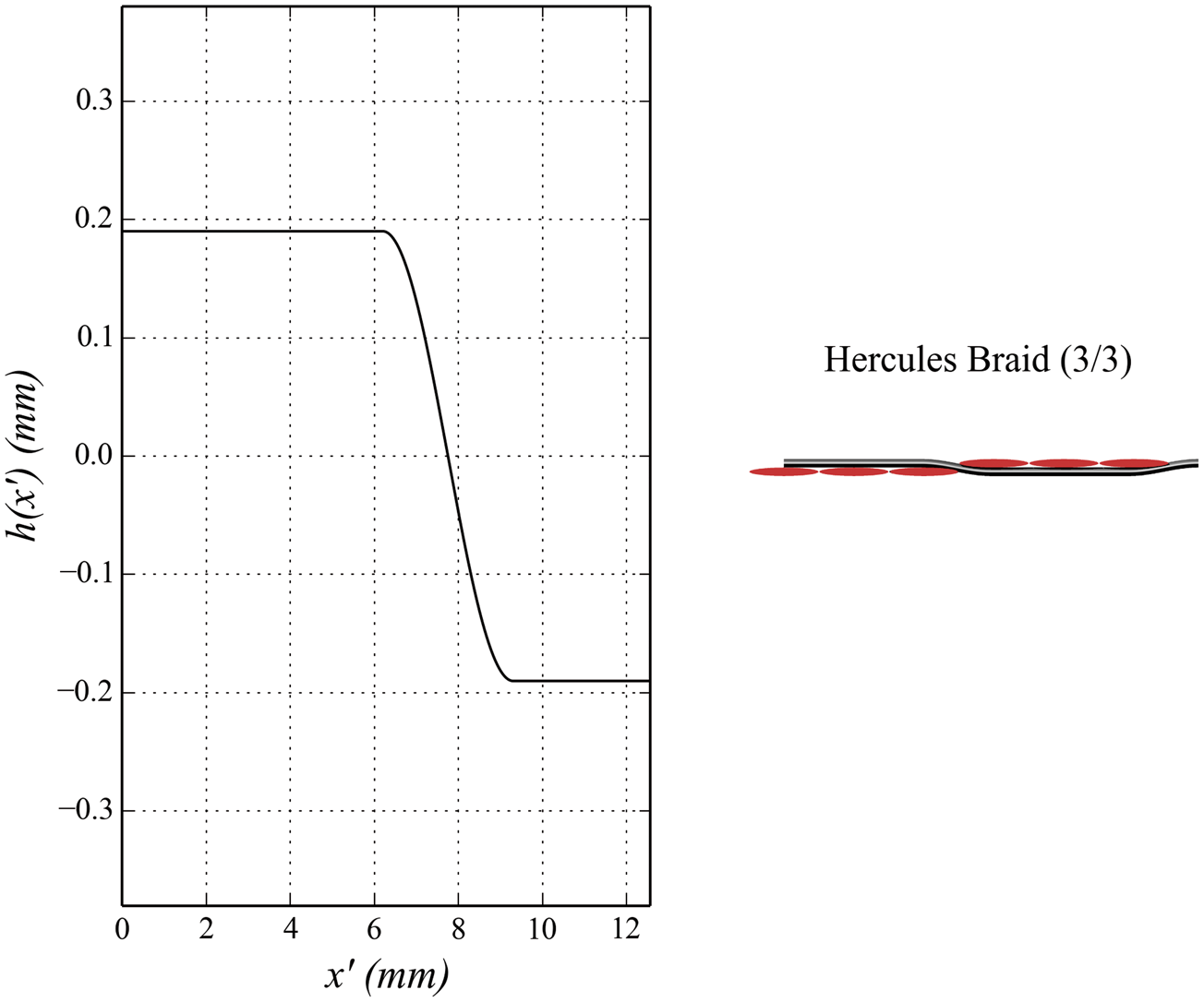
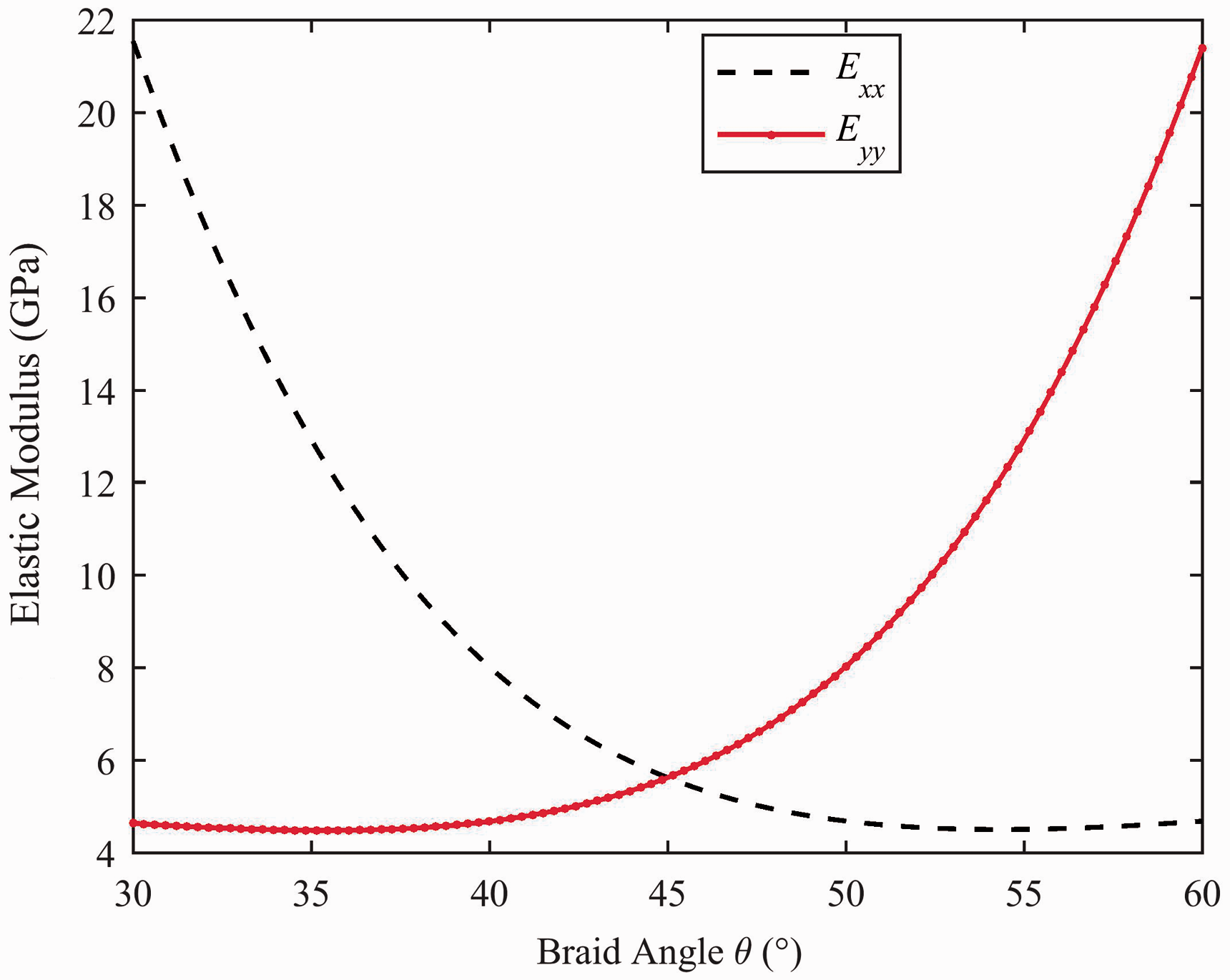
The stand path of a Hercules braid is demonstrated in Figure 16. Similar to the Regular braids, Hercules braids exhibit regions where no yarn undulations occur. Since Hercules braids exhibit less yarn undulation than Diamond and Regular braids, this leads to in an increase in in-plane elastic properties compared to Diamond and Regular braids. The effect of braid pattern on the elastic properties is demonstrated in Figure 17. The Hercules braid is included in this manuscript to demonstrate the capability of the proposed braid model. Experimental validation of the Hercules braid results was not performed as it is not possible to manufacture Hercules braids using a 36 carrier braiding machine; therefore, a comparison with other braid patterns (Diamond and Regular) was not possible. A comparison of the different braiding machine configurations to produce different braiding patterns is described by Melenka et al.
30
Example yarn undulations of a Hercules (3/3) braid. A comparison of longitudinal elastic moduli of a Hercules (3/3) braid.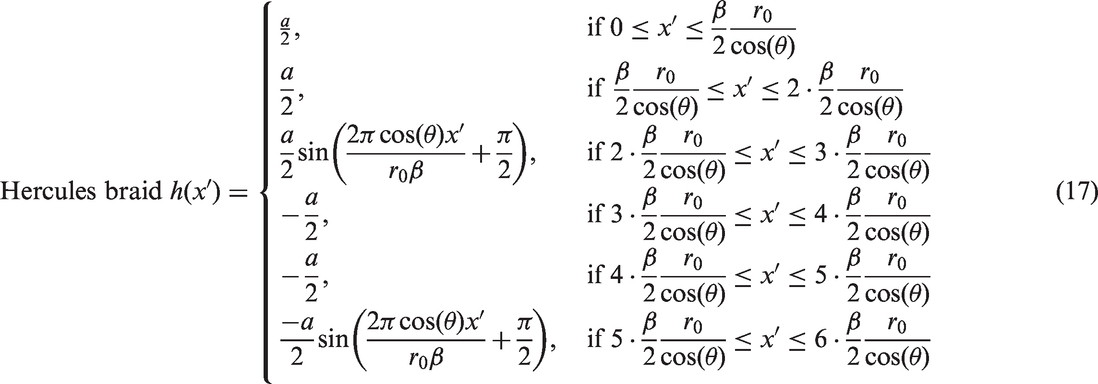
Conclusions
The braid model presented here is a useful method for predicting the elastic constants for tubular braided composites. The presented model is adaptable to a variety of braiding configurations that exist since the model allows for Diamond (1/1), Regular (2/2) and Hercules (3/3) braids to be modeled. The model presented in this manuscript has been validated against the experimental results for Diamond (1/1) and Regular (2/2) braids as these braid configurations can be manufactured using a 36 carrier braiding machine. The model presented utilizes physical parameters utilized during the manufacturing of braids. The ability to use physical braiding parameters allows this model to be utilized during the design of braided composites.
One of the main advantages of the model presented in this manuscript is that this model can be easily implemented using a scripting programming language like MATLAB or Python. Designers can quickly and easily manipulate braid parameters in order to produce a structure with required elastic properties. The analytical model presented in this manuscript is intended to be used as a design tool for designing and manufacturing tubular braided composites and to complement existing FEA models which exist for evaluating tubular braided composites.13,14 Once a suitable braid has been designed using the proposed analytical model a FEA model can then be used to refine the mechanical properties prediction for the particular braid structure. This provides a more computationally efficient process as FEA models will not be required for initial design iterations.