
Abstract
In this work, the performances of circular single- and double-sided composite patch repairs are compared by computing the maximum stress intensity factor of a repaired surface crack. The three-dimensional finite-element method is used to calculate the stress intensity factor along the crack. The effects of the crack depth, composite patch thickness and patch material on the stress intensity factor variation are highlighted. The obtained results show that the selection of single- or double-sided patches depends on both the crack depth and patch thickness.
Introduction
Bonded composite repair has many advantages over a mechanically fastened, which include lower density, improved fatigue behaviour, reduced costs, and excellent formability.1,2 It also provides more uniform and efficient load transfer into the repair patch and less stress concentration. 3 Up until today, however, the certification rules applicable for primary bonded structures prevent the use of boltless bonded joints; 4 therefore, the need to gain knowledge about their behaviour under different conditions and crack types is apparent, and has been a topic of several researches during the last two decades.
The structural stability of bonded composite repairs depends on their mechanical performance during their service life, and most reports dealing with design of bonded patches emphasise the need to have an accurate tool for evaluating repairs against all criteria, measuring crack resistance curves, 5 and predicting stress intensity factors (SIF) and failure strength. 6 There are several methods to perform this analysis, which can be divided into two main groups: analytical and numerical. In general, the analytical method uses elasticity solutions and provides accurate solutions with a small amount of inputs; 3 although, to predict the failure load of a patch-repaired structure, a 3D configuration is required as the stress results can be used to identify critical regions. 7 As a result, due to the increase of computational power, the finite element method has contributed considerably to the knowledge of the mechanical behaviour of defects under patch repairs and has been used by many authors,8–10 finding a detailed review of its application to adhesively bonded repair in Xiaocong. 11
Considering the fact that the geometry and materials of a repair patch are usually determined at an initial design stage and cannot be easily changed, optimisation of repairs should be feasible and reasonable. Some design parameters that have been identified to play important roles in bonded composite patches include: patch size, shape, material selection, and adhesive properties. 12
A way to design a patch repair can be performing a study of its optimal shape, in order to obtain the maximum safety-cost ratio.13,14 In this regard, Ouinas et al. 15 have analysed the performance of octagonal, circular, and elliptical shapes of patches, using the finite-element method. They concluded that the patch shape has a significant effect on the value of the SIF at the crack tip. Ramji et al. 9 have compared the repair performance of patches with circle, rectangle, square, ellipse, and octagon shapes by using the finite-element method, and they found that the octagonal and rectangular patch shapes were better for mixed-mode problems. In spite of the wide range of shapes studied, only double-sided patch repairs were analysed.
The use of single- and double-sided patch repairs has been widely covered in literature, and many authors have studied the influence of both patch configurations on the performance of externally bonded patch repairs. Ramji and Srilakshmi 16 have carried out a three-dimensional finite element analysis to study and compare the performance of single- and double-sided patch on center-cracked aluminum panel. They have shown that the mechanics of both type of repairs is completely different, and concluded that double-sided patch is more efficient. They also highlighted that in case of the single-sided repairs, KI at the unpatched surface exceeded the value obtained in unrepaired panels due to out-of-plane bending. Ouinas et al. 17 have conducted a numerical analysis for studying the repairing cracks from a semicircular lateral notch, determining the SIF for different inclination angles. They observed that the double-sided repair allowed the elimination of the mentioned bending effect, but led to a gain in thickness that was not neglegible in both mode I and mixed mode cases. Albedah et al. 18 have used finite element analysis to estimate SIF for single- and double-sided repairs having a circular patch shape. They concluded that the mass gain given by the double-sided repair can be very significant, depending on both the patch shape and the adhesive properties, and emphasised the difficulty to follow the crack propagation of double-sided repairs. Regarding the adhesive, Bachir Bouiadjra et al. 19 analysed the effect of a disband occurring for cracks repaired with boron/epoxy patch, and they concluded that the SIF is increased by the presence of the adhesive disband.
Thin repaired plates have been modelled in the aforementioned works to represent the skin of an aircraft and a reduction in SIF while using double-sided patches has been observed; nevertheless, not all reparable structures are accessible from both sides, and therefore double-sided patches are not suitable for all applications. The increasing use of composite patching for naval applications has led some studies to consider the use of patches in thicker plates,20,21 and the behaviour of thicker repaired components can be different from those observed in thinner plates.
These previous works focus on analysing the performance of structures with repaired straight-fronts cracks, although fatigue failures in structures usually occur from the initiation and propagation of cracks from notches or defects in the material that is either embedded or at a corner, which propagate with elliptic or near-elliptic cracks fronts.22,23 There is a lack of knowledge in the analysis of the mechanical response of thick metallic panels with through-the-thickness cracks, which initiate near regions of stress concentrations and may cause premature failure of aircraft landing gears, spars, stiffeners, and other components. 24 In this context, realistic assessment of failure conditions requires an accurate determination of SIF and a detailed study of the patch performance.
In the present study, a linear 3D finite-element analysis is performed to investigate the influence of bonded patch repairs on the performance of a thick metallic cracked panel. The study is conducted for aluminium panels and the composite patch is of UD configuration. Different geometries, materials, and crack depths are considered. Particular attention is given to the performance of double-sided compared to single-sided patches.
Geometrical and material properties
The basic geometry of the cracked structure under study is shown in Figure 1, in which a rectangular elastic aluminium plate with a central surface crack is subjected to a remote uniaxial tensile load in the vertical direction (stress amplitude = 70 MPa). The plate is made of aluminum alloy T3 of dimensions 254 × 254 × 12 mm3, and it contains a semi-elliptical crack of length 2a and depth c, as detailed in Figure 1(a). The thickness of the plate is taken from the experimental work presented by Jones and Chiu.
25
Geometry of the model: (a) perspective view and (b) side view. All dimensions are in mm.
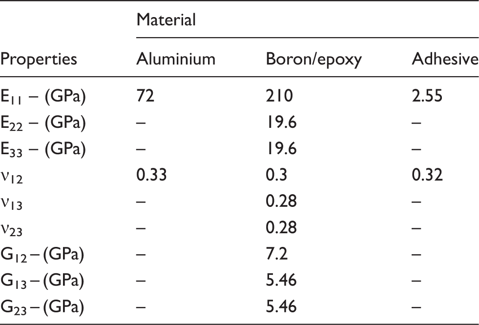
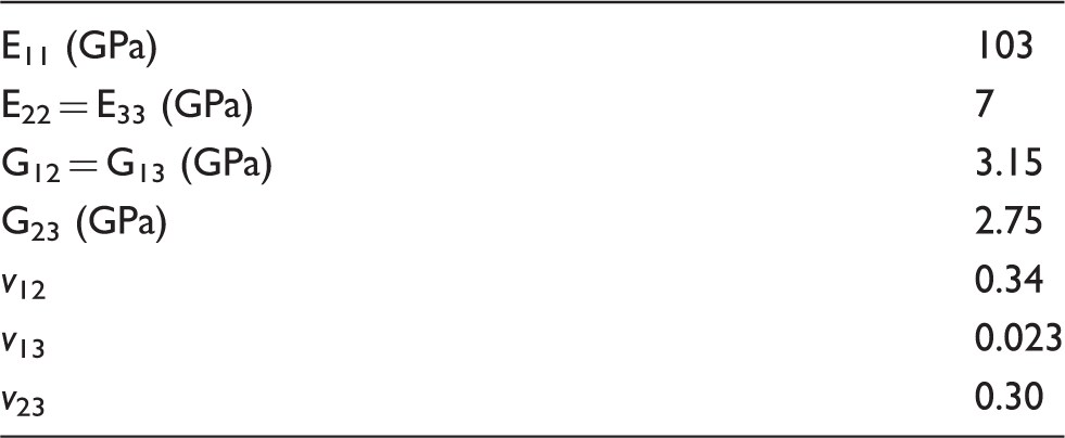
The crack is repaired with a bonded unidirectional boron/epoxy composite patch, in which the fibre direction is parallel to the direction of the load. Figure 1(b) shows that the thickness of double-sided patch is half of that of the single-sided, following the same procedure presented by Albedah et al. 18
Mechanical properties of aluminium, composite and adhesive.
Finite-element model
A three-dimensional model is implemented using the commercial finite-element code Abaqus/Standard.
26
The finite-element model consists of three parts: cracked plate, adhesive, and composite patch. The symmetry of the problem permitted to represent only a quarter of the repaired structure, therefore the size of the analysis domain and the analysis run time were reduced (Figure 2).
Typical mesh of the finite-element model of the repaired structure.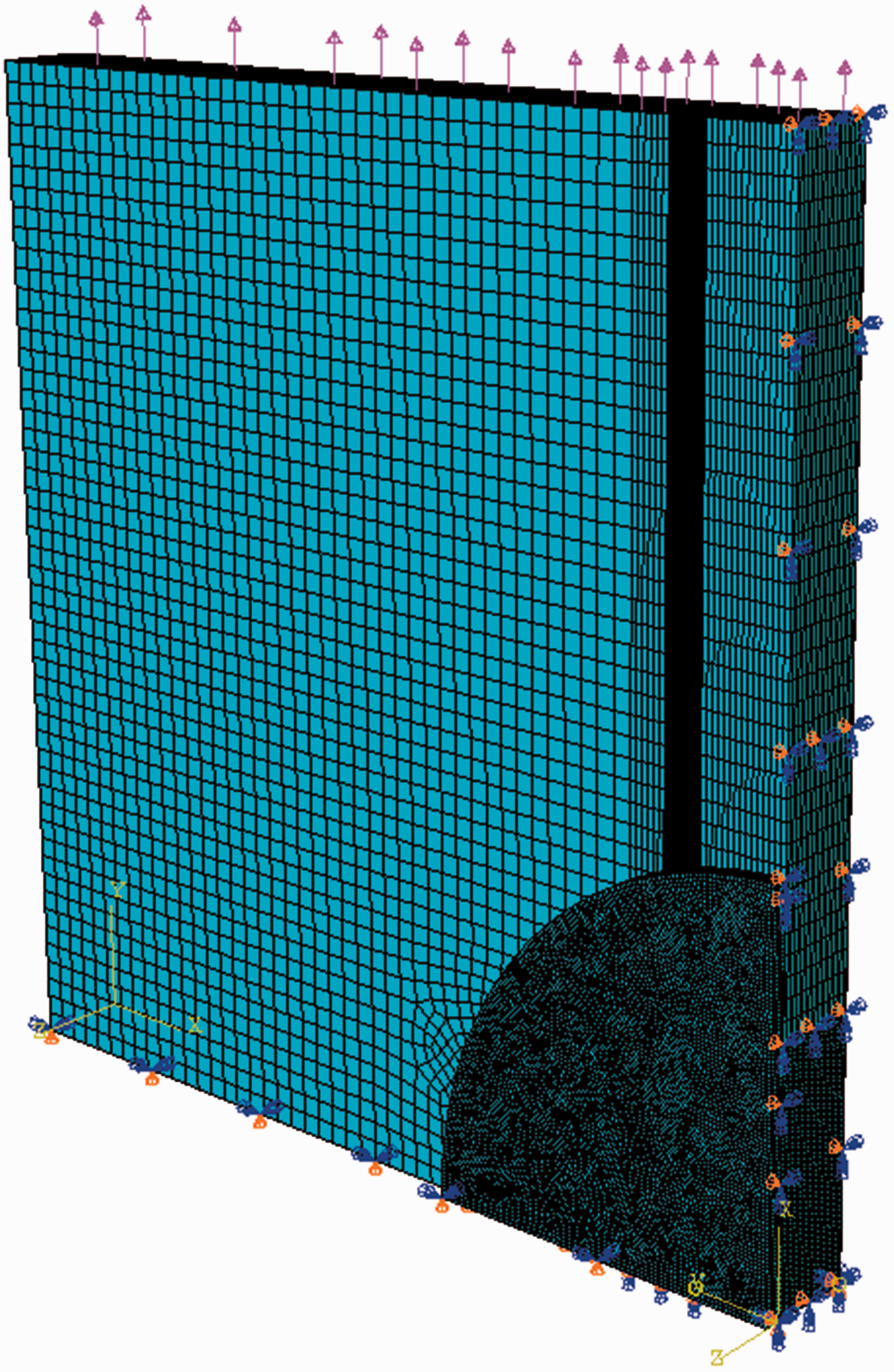
The contact between the different parts is assumed to be perfect9,10 and modelled by means of tie constraints, which are available in the Abaqus/Standard library.
26
The aluminium plate was pulled in tension,
To capture the high stress gradient existing along the crack tip, the mesh has been refined around this area, where the element size is reduced to a dimension of 0.015 mm. Before performing further simulations, the sensitivity of the mesh was evaluated by carrying out successive space discretisations and analysing the mode I SIF of the repaired structure. The SIF is calculated using the J-integral, which is based on the virtual crack extension method available in the commercial FE package Abaqus. For each point of the crack, ten integration contours are computed. Each contour is defined in the normal direction of the semi-elliptical crack front.
The quarter-elliptical surface crack is meshed with 45 elements along its perimeter, hence 45 values of SIF are obtained along the crack tip. For each studied configuration, the result presented corresponds to the maximum value of SIF obtained in each simulation. The adhesive is meshed with one solid element through its thickness, and the patch is meshed with four solid elements through the thickness. The aluminum plate and the adhesive are meshed with 336440 and 9858 elements, respectively, while the patch is discretised with 9858 elements for each milimeter of thickness. All parts are meshed with C3D8R elements (continuum three-dimensional reduced integration eight node elements).
Results and discussion
The objective of this work is to compare the performances of circular single- and double-sided patch repairs by computing the maximum SIF in mode I at a repaired surface crack. The results obtained are presented and analysed in the following subsections.
Mesh validation: comparison between analytical and numerical SIF
In this subsection, the three-dimensional numerical model of the unrepaired cracked plate is validated comparing the obtained results with the analytical solution given by Newman and Raju,
22
in which the SIF for an embedded semi-elliptical crack in a finite plate subjected to tension is defined by the following expression


The finite-width correction, fW, has the form

All geometrical parameters and the coordinate system used to define the parametric angle, φ, are defined in Figure 3. Note that equation (1) is valid for Representation of the geometrical parameters and coordinate system.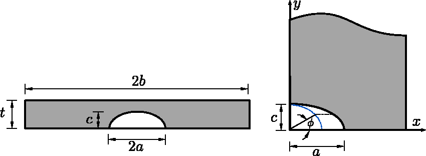
The results of the SIF as a function of the parametric angle are presented in Figure 4. The length and depth of the crack are 12 and 1.5 mm, respectively. The rest of parameters are commented in previous sections. Numerical SIF is very close to analytical SIF, and the difference between them is around 1% when the maximum value is reached. Thus, this confirms the adequacy of the mesh implemented, and similar procedure is considered for further analysis.
Comparison between analytical and numerical results for the obtained SIF.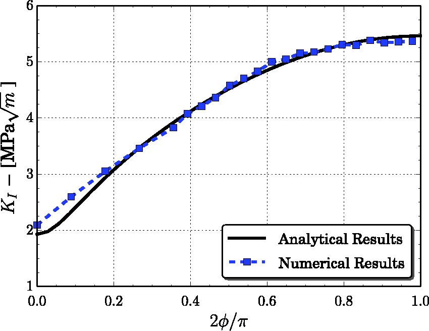
Effect of the crack depth on the SIF variation
Figure 5 presents the variation of the maximum normalised SIF for both single- and double-sided patches as a function of the crack depth (c), normalised with the plate thickness (t). The length of the crack (a) is 12 mm and the radius of the patch is 50 mm. The thickness of the composite laminate is 2 mm for the single-sided patch, and 1 mm for the double. The maximum normalised SIF is defined by
Maximum normalized SIF for single- and double-sided patch vs. normalised crack thickness.
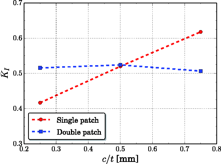
According to the results presented in Figure 5, the performance of the double patch technique is independent of the crack depth, while the effectiveness of the single-patch decreases when the crack depth increases. Results show that the use of single-patched repairs is more effective when the crack depth is less than half the plate thickness, while the double-sided patch performs better when the normalised crack depth is more than 0.5.
Therefore, the selection of single- or double-sided patches will depend on whether the crack depth is less or greater than half the plate thickness. Note that according to the results presented by Albedah et al., 18 the use of a double-symmetric circular patch considerably increases the repair performance in thin-cracked plates having straight-crack front.
Effect of the patch thickness on the SIF variation
The structure studied in the previous section is now considered for different patch thickness (er). Figure 6 shows the variation of the maximum normalised SIF as a function of the patch thickness for both single- and double-sided patches, and for different crack depths (c = 3, 6, and 9 mm). In general, the performance of the repair increases with the thickness of the patch, presenting an asymptotic tendency to a limit of efficiency.
Maximum SIF for single- and double-sided patch vs. patch thickness: (a) c/t = 0.25, (b) c/t = 0. 5, (c) c/t = 0.75.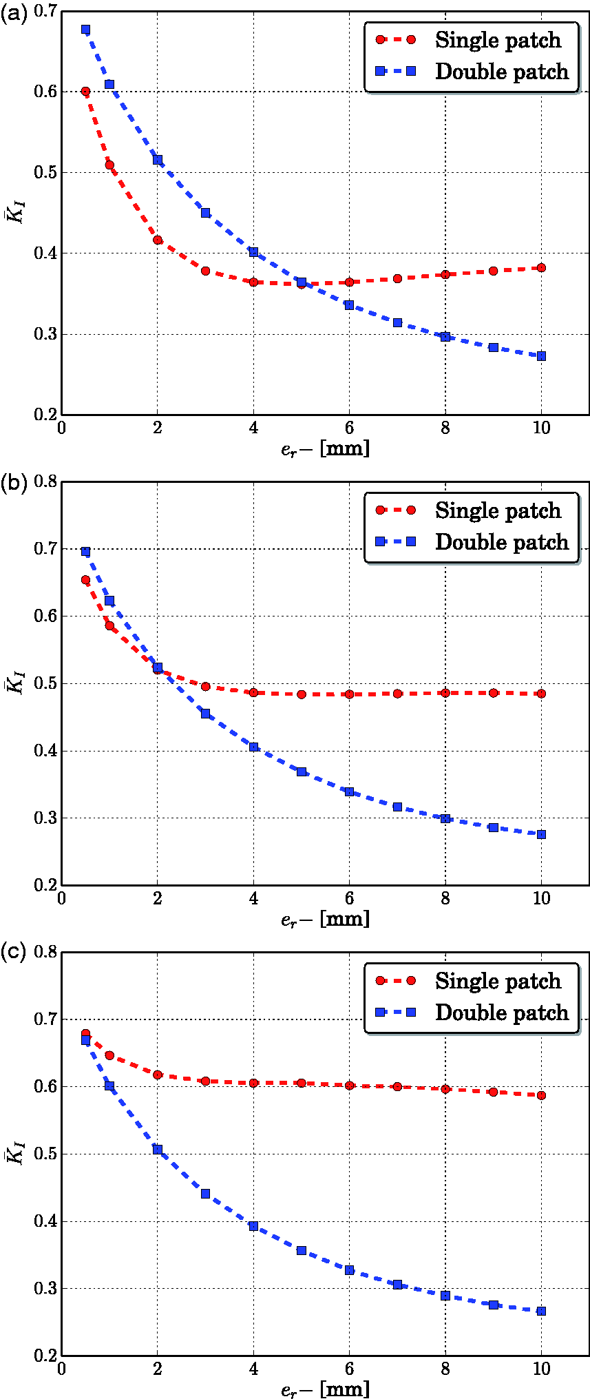
If the ratio of crack depth-to-plate thickness is small (Figure 6a), the thickness of the patch repair seems to be essential to improve the repair performance. For thinner repair patches (<5 mm), it is more useful to use a single-sided patch on the side in which the crack is visible than applying a double-sided, with half the thickness of that for the single-sided. However, single-sided patches prove to have limitations: normalised SIF increases for thicker patches. This could be due to the asymmetry of the repair on which the load is applied: thicker single-sided patches become more asymmetrical with respect to the face without patch. This asymmetry creates a bending field between patch and plate, leading to higher stresses in the vicinity of the crack. 16 Similar results are obtained for surface cracks with depths equal to half the repaired plate thickness (Figure 6b). For surface cracks with depths greater than half the repaired plate thickness, the use of double-sided patches is recommended in all cases (Figure 6c) as the elliptic crack affects the stress distribution in the front and back sides.
Figure 7 presents the difference of the normalised SIF between single- and double-sided patch ( Difference of the maximum SIF between single- and double-sided patch vs. patch thickness.
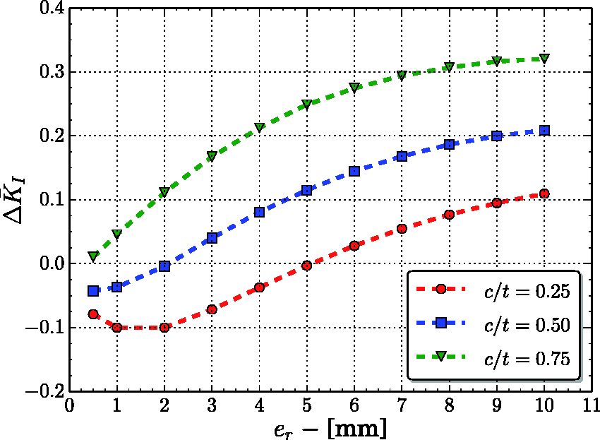
Note that negative values of
Effect of the patch material on the SIF variation
Mechanical properties of composite T600/R368-1. 27
The effect of the variation of the composite patch material on the repair efficiency for single-sided and double-sided repair patches is presented in Figures 8 and 9, respectively. The results are presented as the difference of the normalised SIF between carbon/epoxy and boron/epoxy patch ( Difference of the maximum SIF between carbon/epoxy and boron/epoxy single-sided patch vs. patch thickness. Difference of the maximum SIF between carbon/epoxy and boron/epoxy double-sided patch vs. patch thickness.
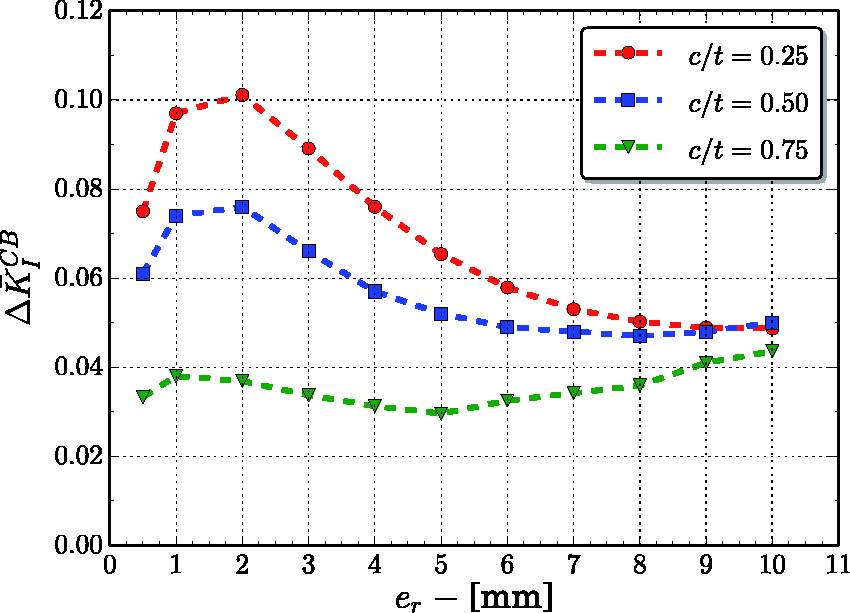
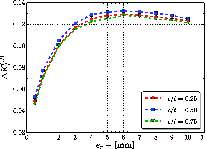
Results show that the repair performance is strongly dependent on the composite patch material. Boron/epoxy patches prove to be more efficent for all cases studied: 0.25, 0.5, and 0.75 crack depth-to-plate thickness ratios. If properties shown in Tables 1 and 2 are compared, it can be seen that boron/epoxy E11 is higher than carbon/epoxy E11, thus this improvement in efficiency is quite evident.
In double-sided repairs the non-dimensional SIF increases with increasing patch thickness for the three c/t ratios studied. Results show similarities in value and trend. In single-sided repairs the non-dimensional SIF decreases with increasing patch thickness. Differences are more noticeable in single-sided repair patches.
Conclusions
In the present study, the influence of single- and double-sided adhesively-bonded composite patch repairs on the mechanical perfomance of thick aluminium plates with semi-elliptical surface cracks is analysed by simulation virtual tests using Abaqus/Standard finite-element code. The repaired cracked plate is subjected to uniaxial tensile load, and maximum value of the SIF in mode I is evaluated. The following parameters are studied: patch configuration (single- or double-sided), patch thickness, crack size, and patch material.
Results show that the choice between using single- or double- sided patches depends on the crack depth, and for surface cracks with depth less than half of the repaired plate thickness, single-sided patch configuration performace is better as compared to double-sided patches, as the crack affects more the side of plate where it is visible. As the ratio of crack depth-to-plate thickness increases, it is recommended to use double-sided patch configuration to repair surface cracks. In all cases, the performance of the patches increases with the thickness of the composite patch. However, due to the increasing asymmetry of single-sided patches with increasing thickness, for surface cracks with depths greater than half the repaired plate thickness, the use of double-sided patches is recommended.
The composite material used for the patch repairs present an important influence on the SIF results, being more noticeable in double-sided patch repairs.
The analysis presented in this work should be useful in predicting the SIF associated to surface cracks with semi-elliptical crack fronts, and in choosing between the use of the single- and double-sided patch configuration depending on the crack dimensions and depth.
Footnotes
Declaration of Conflicting Interests
The author(s) declared no potential conflicts of interest with respect to the research, authorship, and/or publication of this article.
Funding
The author(s) disclosed receipt of the following financial support for the research, authorship, and/or publication of this article: The Ministry of Economy and Competitiveness of Spain (project DPI2013-42240-R).