
Abstract
A meso-finite element model with random voids in matrix is developed to simulate the tensile progressive damage of three-dimensional braided composites. A stiffness degradation method for generating the random void defect element in finite element method is presented. Proper criteria are adopted as initial damage of components, and stiffness degradation is implemented for damage propagation. The tensile strengths are predicted from calculated stress–strain curves. From simulation, void defects in matrix make the redistribution of micro-stress and accelerate the damage propagation of three-dimensional braided composites. Furthermore, void defects reduce the strength and ductility of the composites, but the reduction is not obvious if the porosity is controlled within a range.
Introduction
Three-dimensional (3D) braided composites have great potentialities in aerospace, automobile, marine and other industries because of their excellent mechanical properties such as good structural integrity, high damage tolerance, strong impact and fatigue resistance and excellent designability. In order to make the composites safely applied in primary loading-bearing structures, their structure and mechanical properties have received more and more attention.
There are lots of literatures of 3D braided composites which mainly focus on the geometric structures1–7 and elastic properties8–16 of 3D braided composites. Generally, representative volume element (RVE) (or unit cell) models were used to investigate the properties of 3D braided composites due to their periodical structures. Many researchers studied the structures of 3D braided composites and proposed many unit cell models, such as “fiber inclination model,” 1 “four straight yarns model,” 2 “four bending yarns model,” 3 “three kinds of unit cells”4–7 and “multi-unit cell model.”8,9 Moreover, there are many methods in predicting the effective properties of 3D braided composites, such as laminate theory-based method, 10 strain energy-based method, 11 stiffness volume averaging method, 3 finite element (FE) method12–14 and homogenization method. 15
In recent years, the micro-failure mechanism and strength have become significantly challenging topics for 3D braided composites. Zeng et al. established a multiphase element model for calculating local stress 16 and predicting the nonlinear response and failure 17 of 3D braided composites. Pang et al. 18 and Fang et al.19,20 simulated the microscopic damage behavior of 3D braided composites by means of Murakami’s damage theory and FE method. Dong and Feng21,22 simulated the progressive damage of 3D braided composites by the asymptotic expansion homogenization method. Xu and Xu 23 adopted 3D-Hashin and Tsai-Wu criteria as the criteria of yarns and simulated the damage evolution under longitudinal tension for 3D braided composites. Zhang et al. 24 presented a nonlinear FE model with interface phase to simulate the damage and failure of 3D five-directional braided composites under unidirectional tension. Lu et al. 25 proposed a new damage model based on the Linde failure criterion to describe the damage initiation and evolution in yarns and predicted the longitudinal tensile strengths of 3D full five-directional braided composites. All these studies had got certain achievements that we&re helpful for the strength analysis of 3D braided composites.
Unfortunately, numerical methods mentioned above have generally assumed that the materials have no internal defects and do not consider the effect of random pore defects on their mechanical properties. In fact, since 3D braided composites are generally compounded by RTM forming process, it is almost impossible to completely avoid the existence of defects in the composites. Now, there are few literatures focusing on the effect of the defects on the mechanical properties of 3D braided composites. Liang et al. 26 adopted the Eshelby and Mori-Tanaka theories combined with stiffness averaging method to predict the elastic constants of 3D braided composites. Zeng et al. 27 presented a simplified model of 3D braided composites with transverse and longitudinal cracks to calculate the effective elastic properties of 3D braided composites. Lu et al. 25 studied the influence of pore defects to 3D full five-directional braided composites on stress–strain curves by FE method. Xu and Qian 28 developed an RVE model to predict the elastic properties of 3D braided composites containing two basic types of defects, voids and dry patches. Although all these researches have taken into account the internal defects, they only studied the elastic properties or the constitutive relationship of 3D braided composites but not related to the micro-failure mechanism of these materials.
In this paper, the main objective of the work is to study the effect of void defects on the micro-failure mechanism and tensile strength of 3D braided composites. Firstly, based on a microstructure unit cell model, an FE model considering the random distribution of void defects in matrix is proposed in the section of Meso FE modeling with defects. Then, Section 3 gives the micro-damage criteria for components and the stiffness degradation scheme. Afterwards, the numerical simulations and detailed data analyses of the damage propagation and strength are conducted in Section 4. Finally, some valuable conclusions are obtained in Section 5.
Meso FE modeling with defects
Geometric model of unit cell
Despite the complexity of macro structures, 3D braided composites can be divided into RVEs by the periodicity of their meso structures. Based on the typical structure, 3D braided structures are extensively divided into three kinds of RVEs (i.e. interior RVEs, surface RVEs and corner RVEs).
4
Generally, if the column number and the row number of yarn carriers are large enough, surface RVEs and corner RVEs can be ignored reasonably. Therefore, interior RVEs are the only consideration for our following FE analysis. According to the four-step procedure, the distributions of three kinds of RVEs in 3D braided composites are shown in Figure 1. Considering the periodical distribution of two kinds of interior sub-cells, a unit cell which is the smallest RVE is selected as shown in Figure 1.
Distribution of unit cells on the cross-section of braided preforms.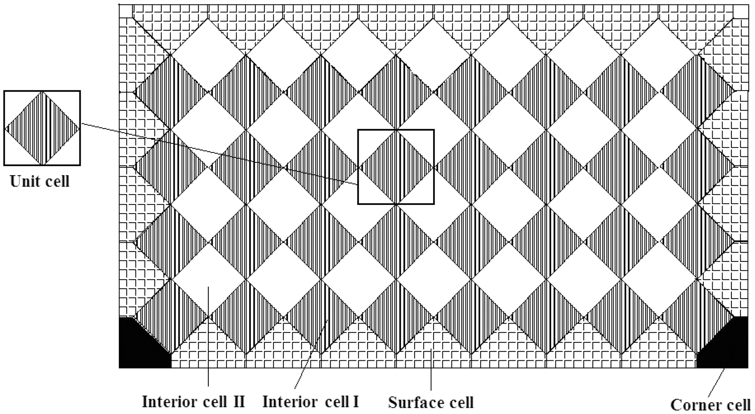
The following assumptions are made to establish RVEs of 3D braided composites:
Based on the experimental observation,
29
and supposing that all the fiber bundles contact closely, the cross section of each fiber bundle is assumed to be a circumscribed octagon of an ellipse (shown in Figure 2). It is assumed that there are no mutual immersion and large voids between fiber bundles; The braiding procedure is maintained relatively steady and the braided structure is uniform; The fiber is regarded as transversely isotropic in elasticity, and the matrix is isotropic; Fiber bundles have adequate flexibility. Section of braiding yarn.
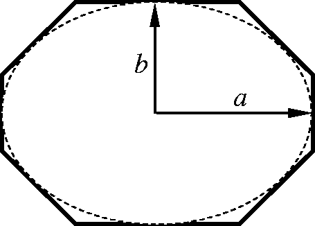
According to the assumptions above, the cross section of a fiber bundle is assumed to be an octagon, and the octagon contains an inscribed ellipse with major and minor radii, a and b, respectively. When the yarns are jamming and contact each other, the relationship between a and b can be deduced as follows
4

The total cross-sectional area of fibers in a fiber bundle is given by

Defining the yarn packing factor κ as the fiber volume fraction in a fiber bundle, the cross-sectional area of a fiber bundle, denoted by Ab, is

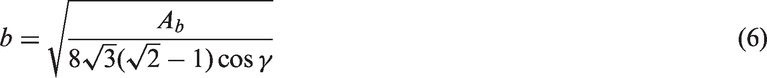
It is known from the assumptions that the cross section of a fiber bundle is a regular octagon before extrusion. The octagon contains an inscribed circle with radius b. Assuming the area of the regular octagon is A1, the relationship between A1 and Ab is

The area of a regular octagon can be simply calculated by

Combining equations (1), (4) and (5) yields
The dimension of the unit cell in the braiding direction is called the braiding pitch, denoted by h. The width Wi, the thickness Ti and the pitch length of the unit cell are, respectively


By analyzing the track movements of the braiding yarn carriers during a machine cycle according to Chen et al., 4 the spatial locations of the yarn axis in a unit cell can be obtained.
Assuming the cross section of the yarn is octagonal and calculating the parameters a and b according to equations (1) and (6), the geometric model of unit cell is established using the software ANSYS. Figure 3(a), (b) and (c) shows the geometric model of yarns, matrix and unit cell, respectively.
Geometric model of unit cell. (a) Yarns, (b) matrix and (c) unit cell.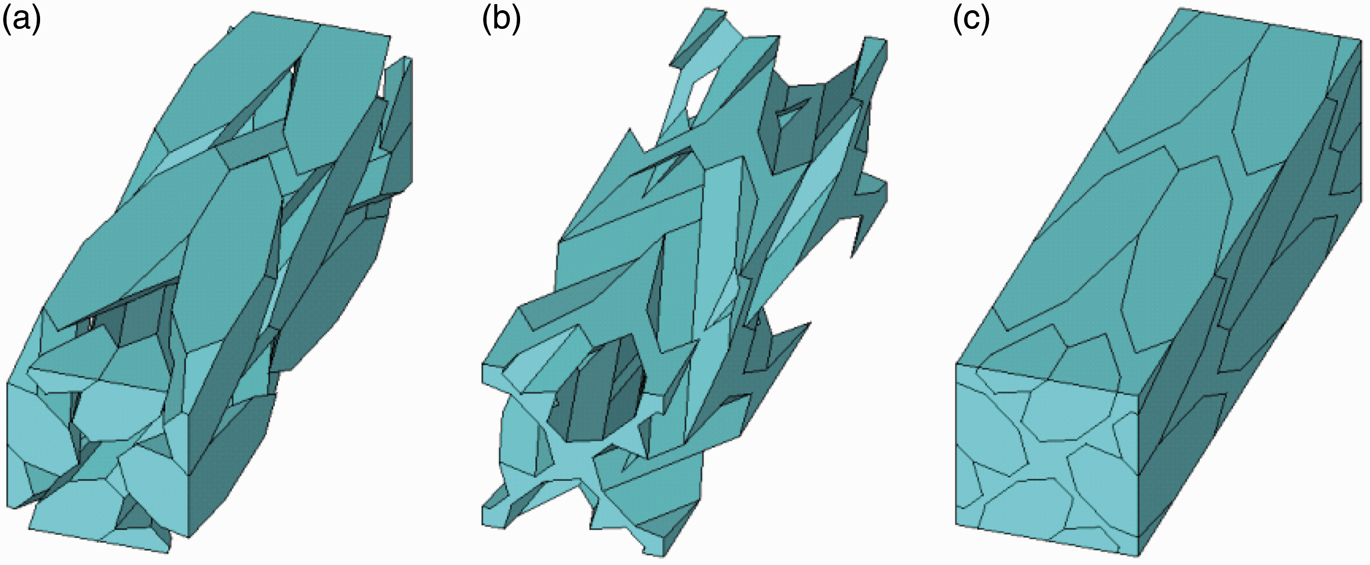
FE model of unit cell
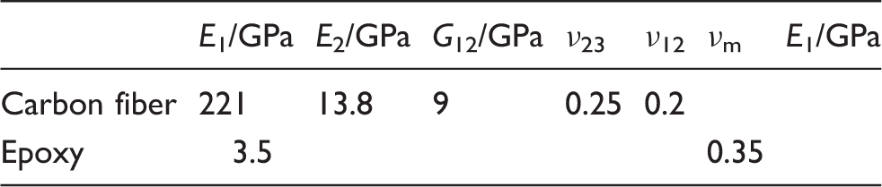
The 3D braided composites are composed of yarns and resin matrix. The resin matrix is assumed to be isotropic and the yarns are regarded as transversely isotropic. The on-axis elastic constants of the yarns can be obtained by using the micromechanics formulae given by Chamis
30
as follows
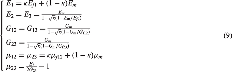
In order to avoid stress transformation in the following damage analysis, local coordinate systems O′x′y′z′ are defined as the principle direction systems of yarns. In the local coordinate systems, z′-direction denotes the axis direction of yarns, the coordinate plane of O′x′y′ denotes the plane of cross section of each yarn. For the unit cell, there are four local coordinate systems as yarns have four directions. The yarns and the matrix were meshed respectively in their own local coordinate systems with the 10-node tetrahedral isoparametric element. Figure 4(a) and (b) shows the FE model of the yarns and the unit cell, respectively.
Finite element (FE) model of unit cell. (a) FE model of yarns and (b) FE model of unit cell.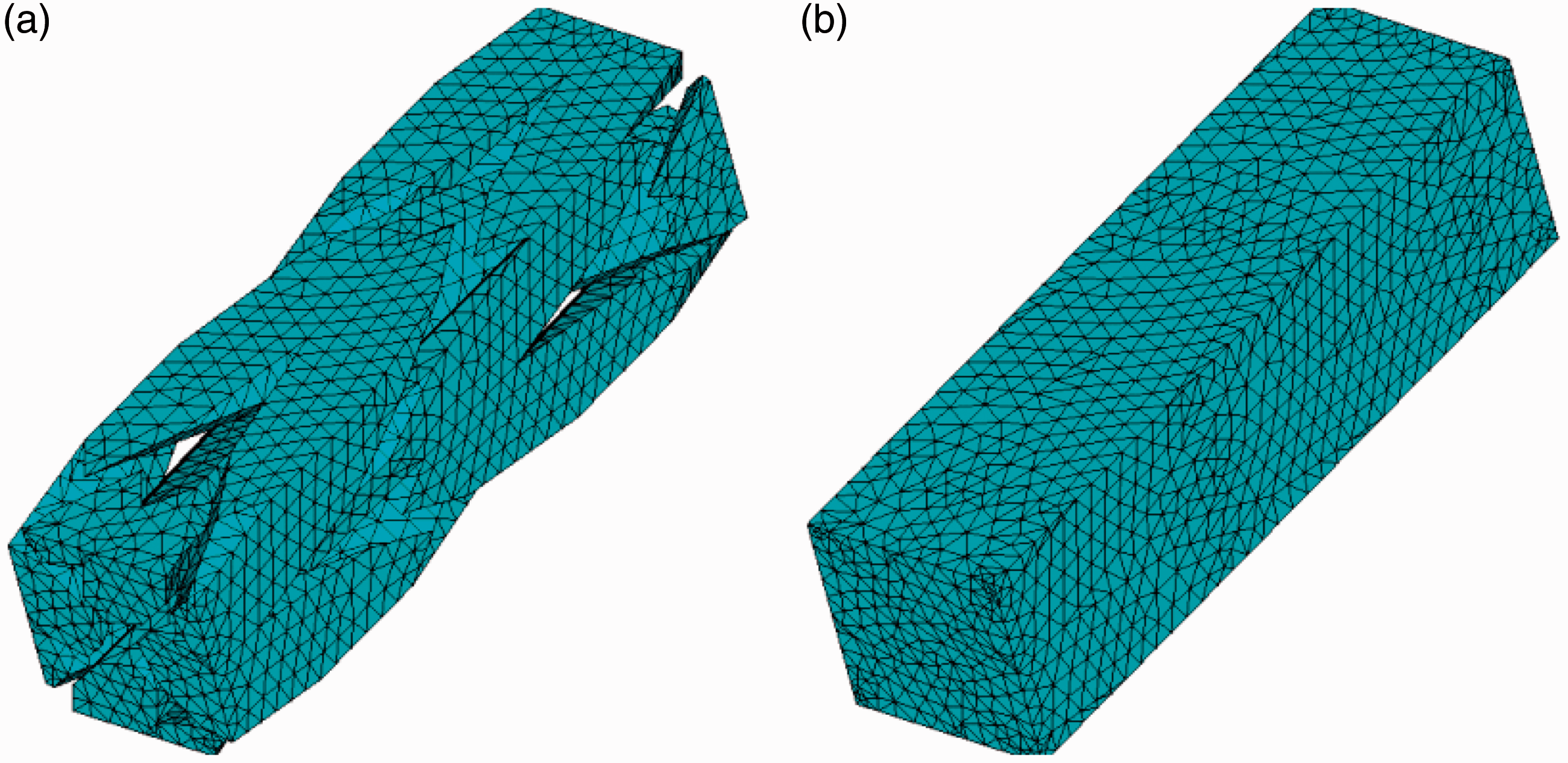
Elements with void defects
During the molding process of 3D braided composites, due to insufficient resin infiltration, pore defects inevitably occurred after curing. Voids in resin matrix are one of the most common types of defects in the resin matrix composites. Their formation is due to the low permeability of flow across the yarns as shown in Figure 5. Only void defects randomly distributed in the matrix are considered in this article.
Formation of voids in matrix.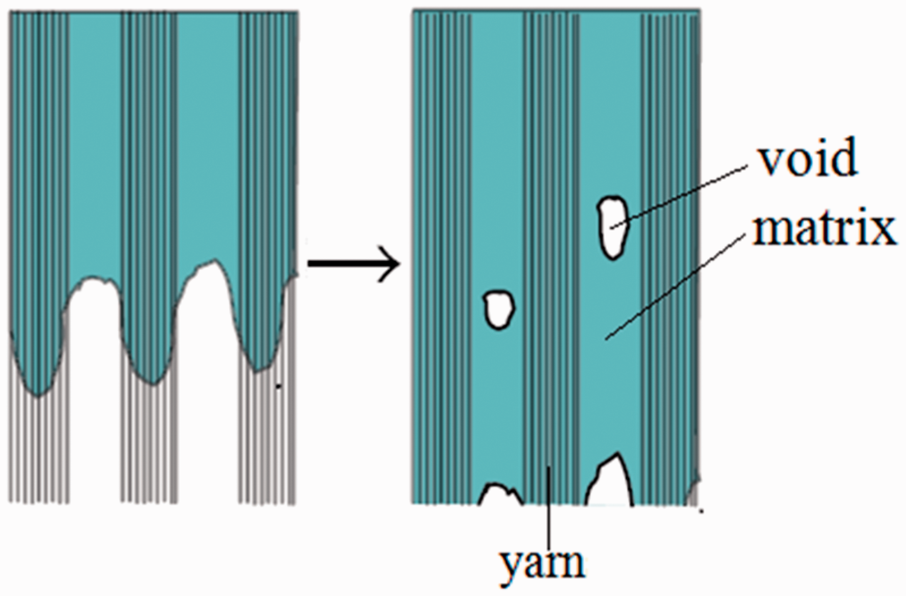
The void volume fraction, namely porosity, is defined as the ratio of the void volume to the unit cell volume. In the model, the porosity, denoted by Pmv, is used as a parameter to control the number of void elements. For any void element, it is assumed that its stiffness is reduced to zero. Thus, the method of endowing the FE model of unit cell with random void defects is as follows: Firstly, a matrix element is randomly selected and its elastic modulus and Poisson’s ratio is reduced by 99.99%. Then, continue to select other matrix elements randomly and reduce their stiffness, until the volume fraction of all selected elements is greater than the porosity. Figure 6 shows the zero-stiffness void elements in the unit cell with the porosity of 3% and 5%.
Zero-stiffness void elements. (a) Pmv = 3% and (b) Pmv = 5%.
Progressive damage model
Damage criteria of components
The failure of heterogeneous composites is the result of damage accumulation. Therefore, it is important to choose proper criteria for components of the composites. For 3D braided composites, porosity near interface may cause weakness along interface, where damage is commonly initiated. However, the constitutive and damage model for interface is hard to define. Therefore, in order to simplify the analysis, interfacial debonding is ignored in this paper.
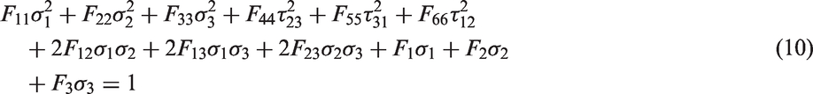
The yarns can be regarded as transversely isotropic material, so the Tsai-Wu second-order tensor polynomial equation (10) is adopted as the criterion of every yarn element
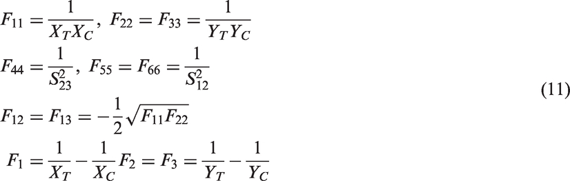
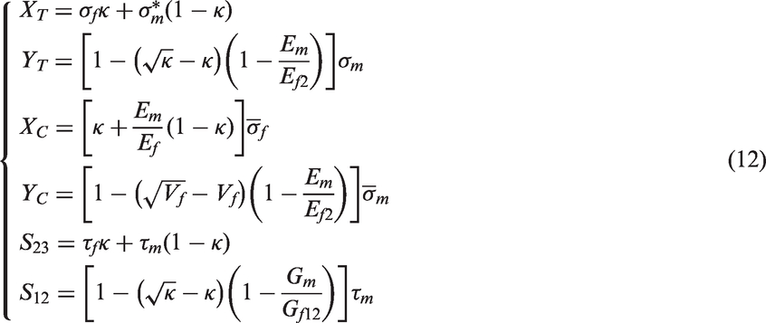
Based on some empirical formulas for predicting the strength of unidirectional composites,
30
the strength parameters of yarns are expressed as
The matrix is isotropic and for each matrix element, the von Mises criterion is adopted as its damage criterion, i.e.

Damage patterns of yarn
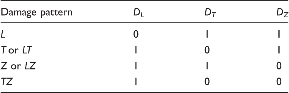
Due to the transverse isotropy of yarns, there are four kinds of damage patterns in yarns: longitudinal breakage, transverse cracking, longitudinal shear damage and transverse shear damage.
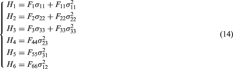
From the Tsai-Wu criterion equation (10), the damage pattern of each yarn element can be judged by maximum value of Hi (i = 1, 2, 3, 4, 5, 6) defined in equation (14)
Stiffness degradation scheme
Geometric damage theory proposed by Murakami and Ohno
31
considers that the reduction of effective loading for damaged model is equivalent to the reduction of effective load-bearing area for undamaged model. Defining

The value of Di denotes the reduced value of load-bearing area and can be expressed as

Due to the reduction of effective load-bearing area, the relationship between the undamaged stress and the effective stress can be written as

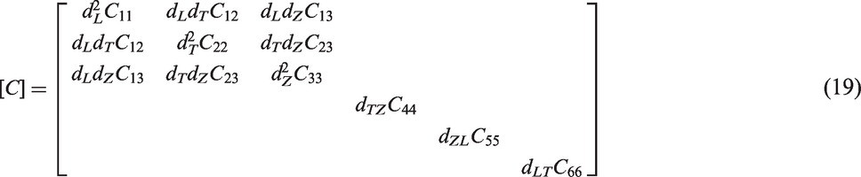
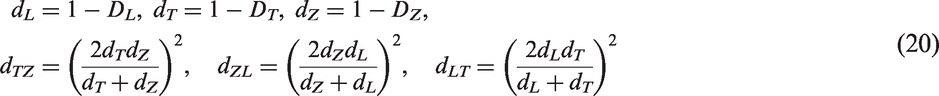
The stiffness matrix of damaged materials can be deduced as

Then, substituting equation (17) into equation (18), it follows that
Damage pattern and principal value of damage tensor.
It is regarded that the matrix loses load-bearing capacity in all directions because it is isotropic and so for damaged matrix element, the stiffness is reduced to zero. In this paper, according to Zeng et al., 17 the stiffness matrix is reduced by 99.9%.
Numerical simulations and discussion
Periodical boundary conditions
As mentioned above, 3D braided composites have periodical structure distributions. According to Xia et al., 32 periodical boundary conditions should be applied to the periodical structures.
The displacement of the periodical unit cell is expressed as

From another point of view, the displacements on a pair of opposite surfaces (with their normals along the Xj axis) are


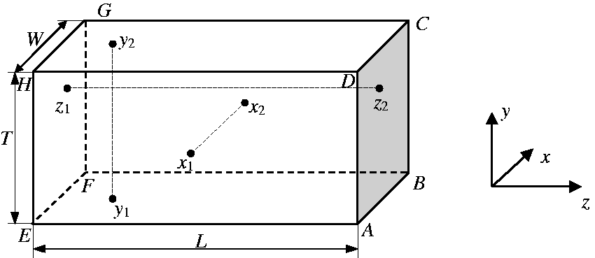
Figure 7 shows a cubic RVE model of an anisotropic material. Here, x1 and x2 are the corresponding nodes along x-axis; y1 and y2 are the corresponding nodes along y-axis; z1 and z2 are the corresponding nodes along z-axis. Supposing z is the longitudinal direction, and the nodal displacement of x, y and z direction are respectively u, v and w, then the periodical boundary conditions for longitudinal tension are expressed as
A cubic representative volume element (RVE) model.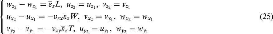
The software ANSYS is adopted to apply the periodical boundary conditions on the unit cell. If a set of nodes have some identical degrees of freedom, the coupling (CP) command should be used to constraint these nodes. On the other hand, if there is a certain relationship between the degrees of freedom of some nodes, a constraint equation (CE) can be defined. Correspondingly, if the right of equation (14) is equal to zero, the nodes coupling will be used, otherwise, the constraint equation defining will be used. Although there are lots of nodes on a pair of opposite surfaces, APDL language in ANSYS can be written to define these boundary conditions easily. The periodical boundary conditions for longitudinal tension load imposed on the unit cell is shown in Figure 8 (here green color represents CP and pink color represents CE).
Periodical boundary conditions for tension. (a) CP in z-direction, (b) CP in all directions, (c) CE in z-direction and (d) CE in all directions. CE: constraint equation; CP: coupling.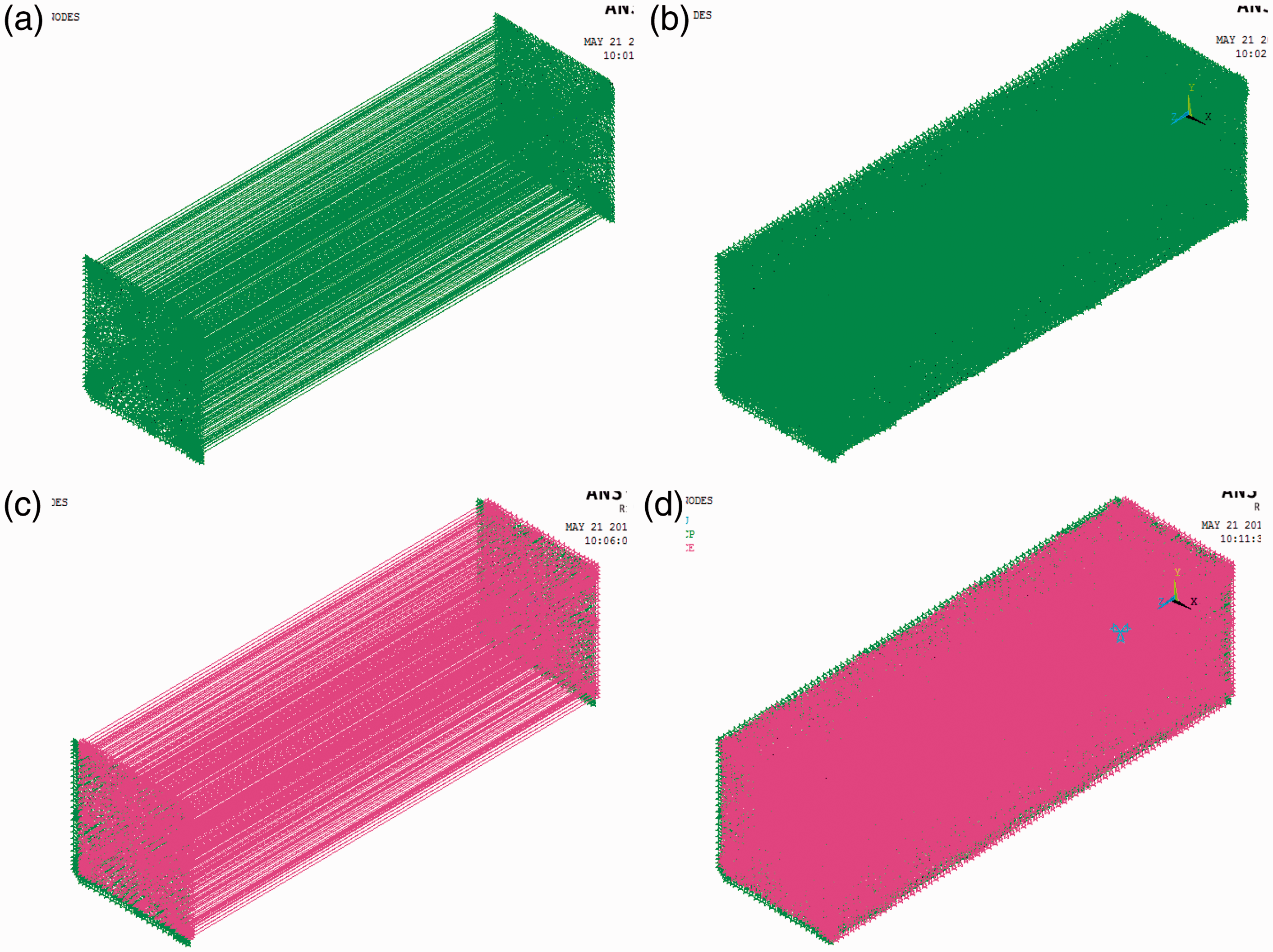
Micro-stress simulation
Elastic parameters of carbon fiber and resin matrix.
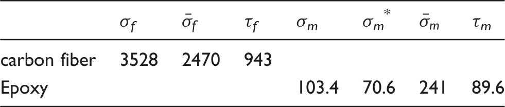
Strength parameters of carbon fiber and resin matrix (unit: MPa).
The longitudinal modulus of the materials is 71.1 GPa, the tensile strength is 665 MPa and the fracture strain is 0.891% according to experimental data.
Based on the periodical boundary conditions for tension, the micro-stress in the unit cells can be simulated, which reflects the heterogeneity of the materials. Figure 9 shows the axial stress in yarns and the Von Mises stress in matrix with different porosity when the average tensile strain is 0.005.
Stress of yarns and matrix with void defects. (a) Yarns (Pmv = 0), (b) yarns (Pmv = 3%), (c) yarns (Pmv = 5%), (d) matrix (Pmv = 0), (e) matrix (Pmv = 3%) and (f) matrix (Pmv = 5%).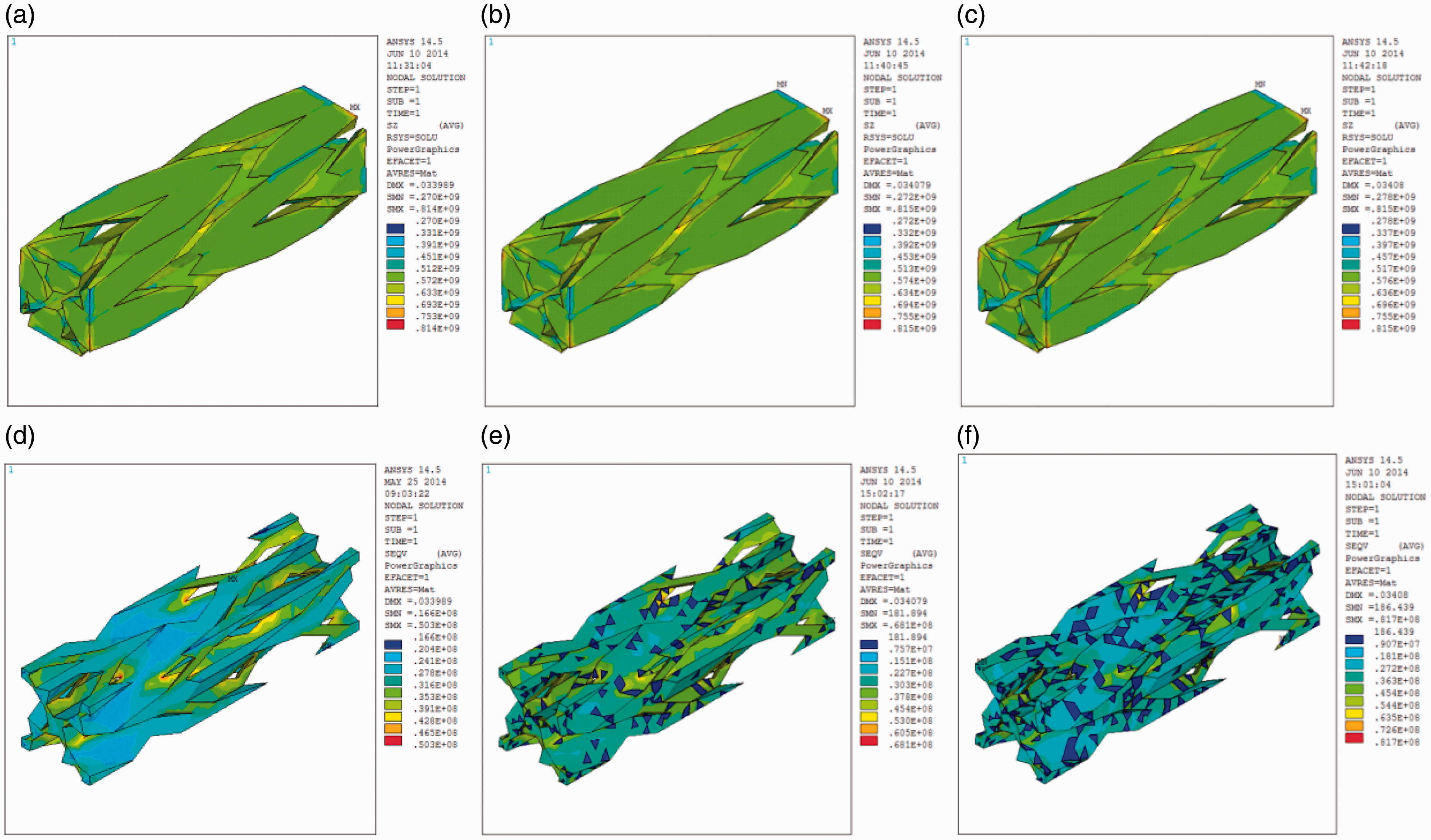
From Figure 9(a) to (c), it is found that the micro-stress in yarns has no obvious change when there are some voids in matrix. But the micro-stress in matrix changes significantly with the increase of void defects as shown in Figure 9(d) to (f). The stress in elements with defects is almost zero, but the maximum value of stress increases from 50.3 MPa to 81.7 MPa when the porosity increases from 0 to 5%. This is because the presence of void defects in matrix causes stress redistribution in matrix but has little effect on the stress distribution in yarns.
Damage propagation simulation
When the micro-stress for each element has been calculated, loads are increased step by step. After each step, each element is verified whether it is damaged with the micro-damage criteria as in Section 3.1. If an element is damaged, the damage pattern is selected by the criteria as in Section 3.2. After each loading step, stiffness degradation method is used for each damaged element according to Section 3.3.
In this example, we use displacement increment method and Damage propagation of components with no defect. (a) Yarns and (b) matrix.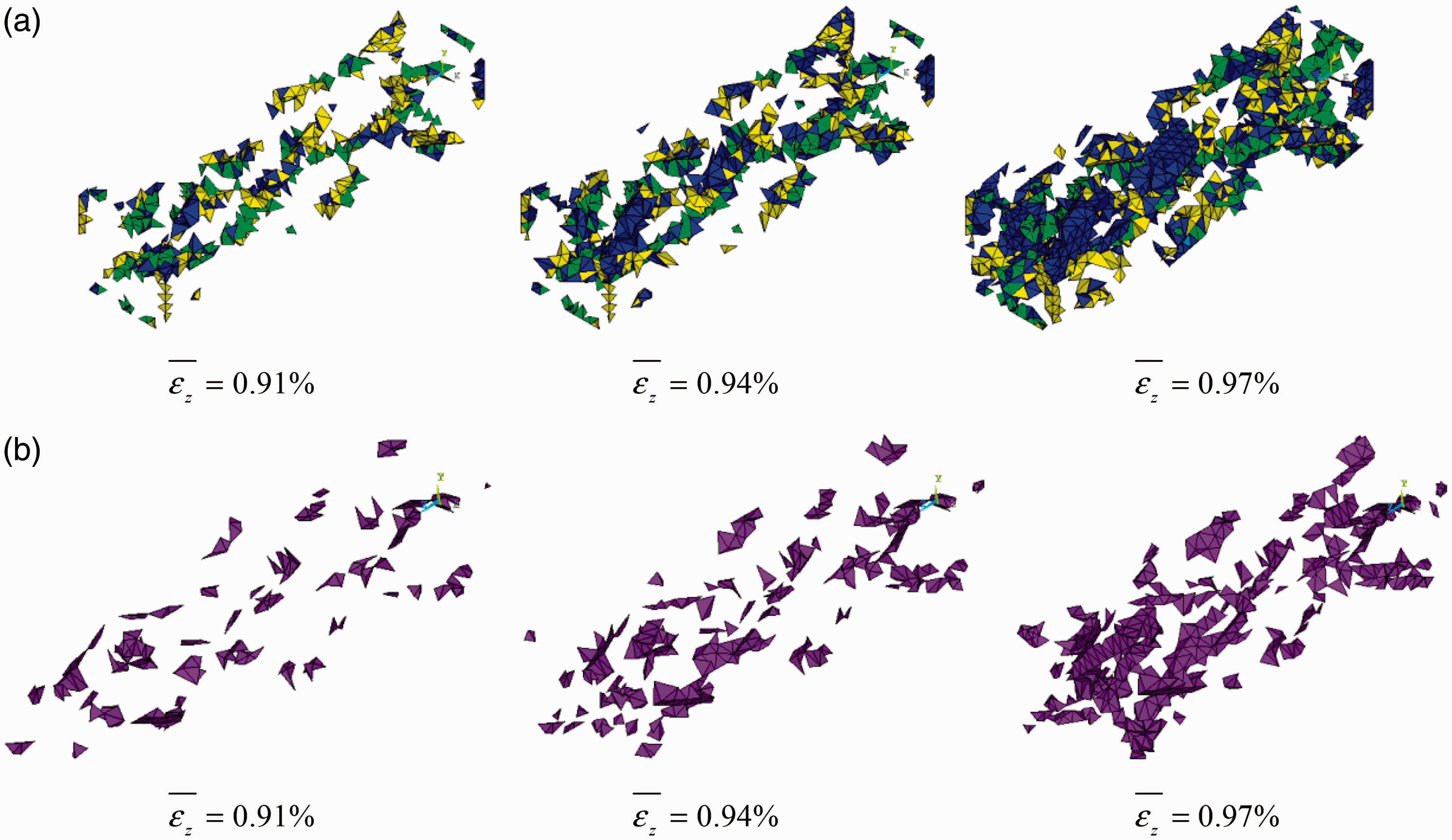
In Figure 10, when the average strain increases from 0.91% to 0.94% and then to 0.97%, the damage percentage of yarns increases from 2.42% to 5.21% and then to 12.23%, while the percentage of matrix increases from 0.3% to 0.74% and then to 2.05%. Obviously, for composites with small braiding angle, there are much more damage elements in the yarns than in the matrix. And the main damage pattern of yarn elements is L pattern. At the beginning of damage, LT or ZL pattern processes a little higher percent than L pattern. But L pattern percentage increase faster than other types of damaged elements. When the structure is going to fail at average strain of 0.94%, L pattern fraction becomes more than LT or ZL pattern and it increases sharply in the subsequent load step. In conclusion, yarn longitudinal breaking is the main reason for the failure of composites with small braiding angle.
Considering the void defects in matrix, as the initial damaged elements cause the stress redistribution, the damage propagation of components will vary with the increase of the porosity. Figure 11 shows the damage propagation of components with the porosity of 3%. On comparing with Figure 10, it is observed that for composites with porosity of 3%, there are more damaged elements in each load step. Particularly, the L pattern damage grows much faster in composites with porosity of 3% than in composites without defects. Thus, the existence of initial voids aggravates damage propagation of 3D braided composites.
Damage propagation of components with void defects (Pmv = 3%). (a) Yarns and (b) matrix.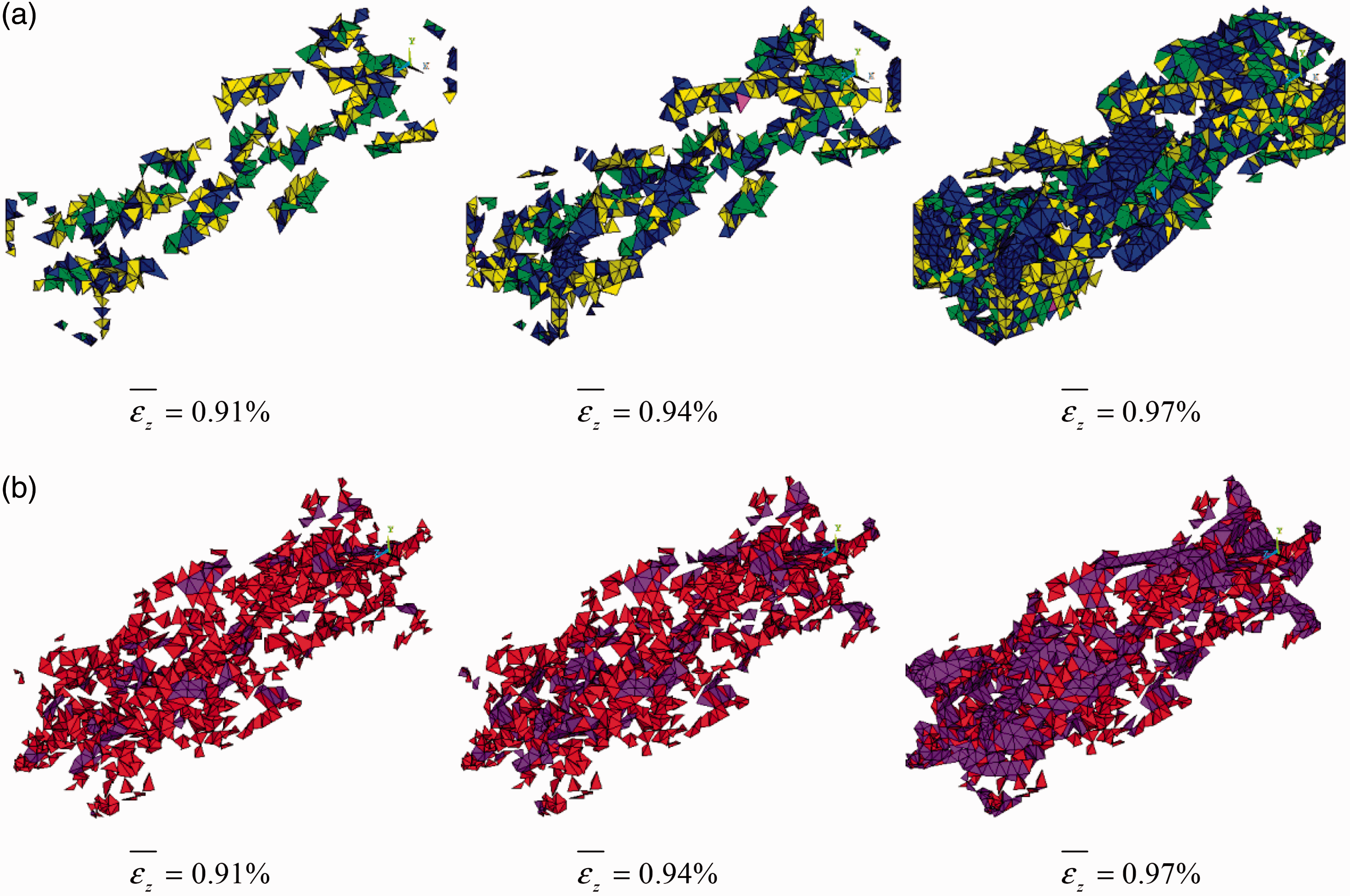
The propagation curves of main types of damage with different porosity are shown in Figure 12, where Figure 12(a)–(c) shows the progressive increase of the L, ZL and LT damage percent of yarns, Figure 12(d) shows the propagation of matrix damage. Above all, it is found that when the average strain increases to about 0.9%, the L pattern is more than other types of damage and it increases more and more sharply with the increase of porosity. However, the ZL pattern firstly decreases when the porosity increases to 3%, but increases sharply when the porosity reaches 5%. The LT pattern increases almost evenly with the increase of porosity. Due to initial damage of void elements, the origin of matrix damage propagation curve with different porosity is different. If the initial damage is not counted, the matrix damage increases slightly with the increase in porosity.
Damage propagation curves with different porosity. (a) L pattern damage of yarn, (b) ZL pattern damage of yarn, (c) LT pattern damage of yarn and (d) matrix damage.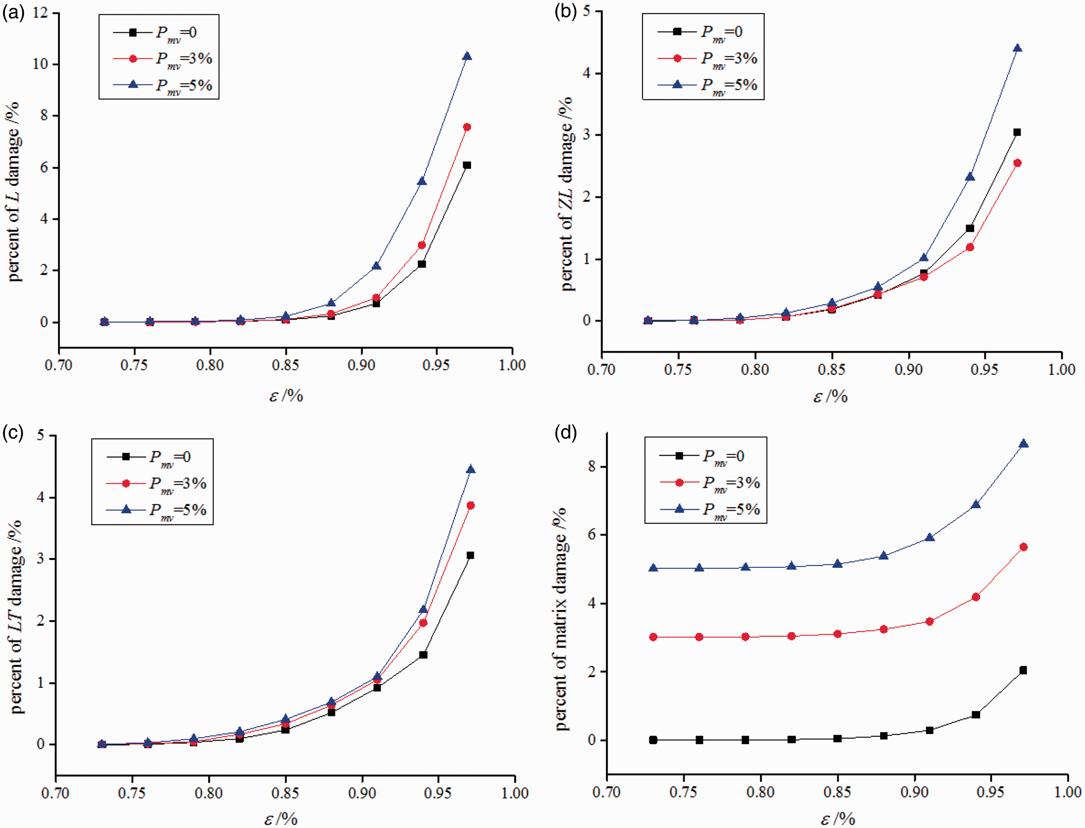
Stress–strain curves and strengths prediction
From the progressive damage simulations, average stress, average strain and stress–strain curves after each step can be drawn. The tensile strength and the fracture strain can be obtained by the maximum point of the stress–strain curve. Figure 13 shows the stress–strain curves of 3D braided composites with different porosity. The tensile strength and fracture strain with different porosity are listed in Table 4. From Figure 13 and Table 4, it is observed that:
Composites with small braiding angle have almost linear constitutive relationship before they break. From the stress–strain curve with no porosity, the longitudinal modulus can be calculated as 71.5 GPa, which is very close to the experiment result 71.1 GPa. The results of the tensile strength and fracture strain from simulations agree well with the experiment results. With the increase of porosity, both the tensile strength and fracture strain decrease. If the porosity is less than 3%, the decrease is not obvious. However, the tensile strength reduces by 3.9% as the porosity increases from 0 to 5%. This reduction is significant and cannot be ignored. Tensile strength and fracture strain with different porosity. Stress–strain curves with different porosity.
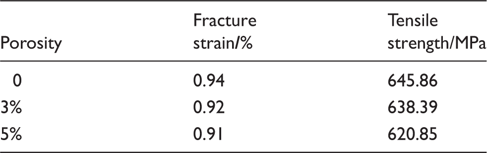
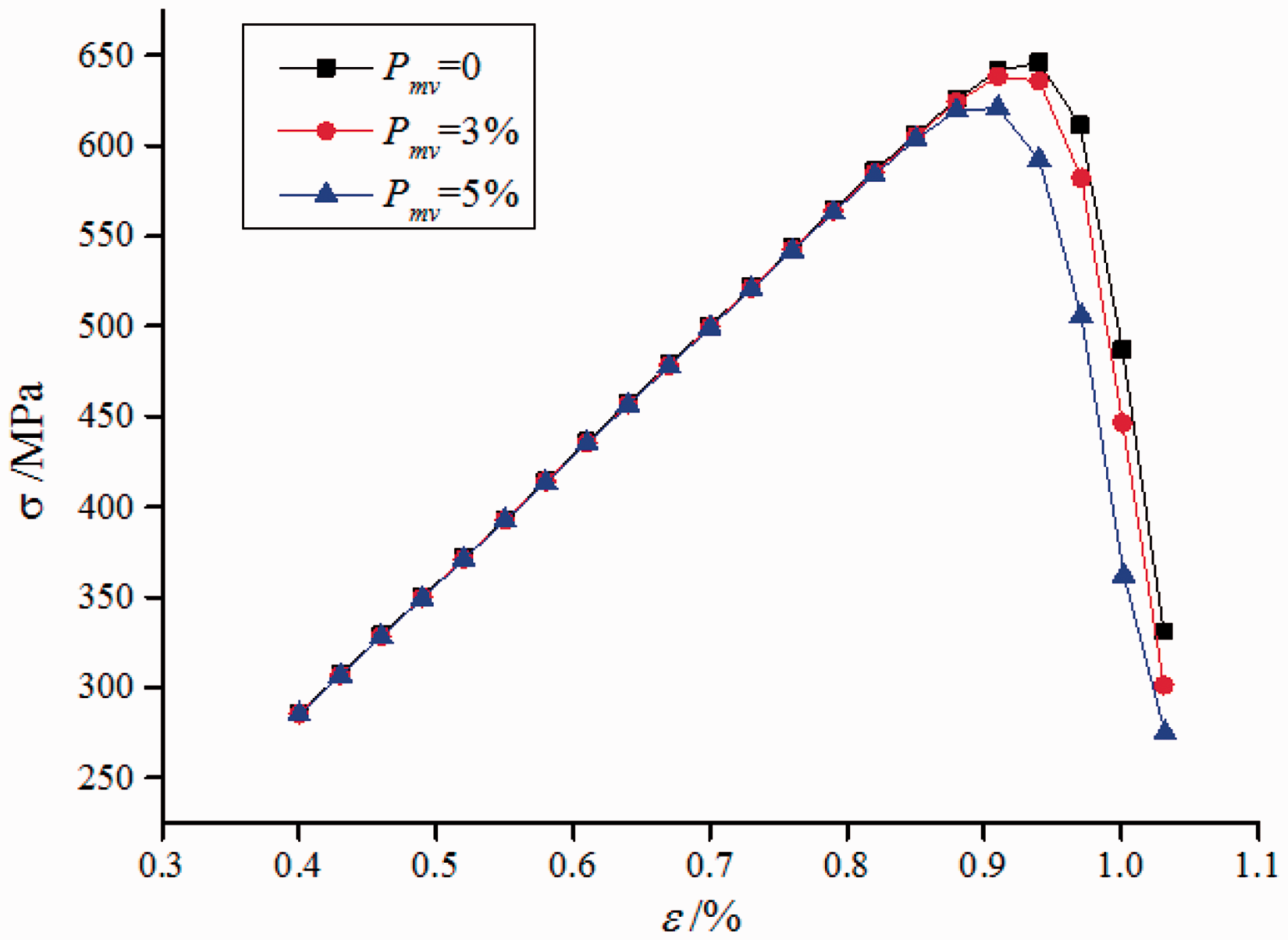
In summary, void defects in matrix will reduce the strength and ductility of the composites. The porosity should be controlled within a range to avoid a remarkable decline in tensile strength.
Conclusions
Considering the initial random void defects in matrix, the progressive tensile damage of 3D braided composites is simulated by the FE method, and then the tensile strength and fracture strain are predicted from the stress–strain curves. Based on the FE model of the unit cell, the void elements are randomly selected and endowed with zero-stiffness elements. Micro-stress in the unit cell is simulated by applying periodical boundary conditions. Tsai-Wu criterion and von Mises criterion are adopted as damage criteria of yarn elements and matrix elements, respectively. The damage pattern of each yarn element is judged by the maximum value of some items in Tsai-Wu polynomial. The geometric damage theory proposed by Murakami is introduced as the evidence of stiffness degradation to deal with the damaged elements. By calculating the average stress and average strain of each loading step, stress–strain curves are drawn and the tensile strength and fracture strain are predicted from the curves. The influence of porosity on the damage propagation and strength of 3D braided composites is discussed. By these results of simulation, following conclusions can be drawn:
Random voids in matrix will cause redistribution of micro-stress in matrix, but will have no obvious effect on the micro-stress in yarns. Yarn longitudinal breaking is the main cause for the failure of 3D braided composites with small braiding angle. The existence of initial voids increases almost every type of damage, especially aggravates longitudinal damage propagation in yarns greatly. The constitutive relationship of composites with small braiding angle is almost linear. Void defects in matrix will reduce the strength and ductility of the composites, but the reduction is not obvious if the porosity is controlled within a range. The calculated results of longitudinal tensile modulus, tensile strength and fracture strain agree well with the experiment data, demonstrating the validity of the method in this article.
Future work will focus on the influence of other types of initial defects, such as dry pots in yarns, micro cracks in yarns and interface debonding, on the strength and micro failure mechanism of 3D braided composites.
Footnotes
Declaration of Conflicting Interests
The author(s) declared no potential conflicts of interest with respect to the research, authorship, and/or publication of this article.
Funding
The author(s) disclosed receipt of the following financial support for the research, authorship, and/or publication of this article: This work is supported by the Fundamental Research Funds for the Central Universities (grant nos.2012QNA54).