
Abstract
This paper reports impact and compression behaviours of three-dimensional angle interlock woven composites after the thermal ageing degradation in both experimental and finite element analyses. The composite coupons have been aged in atmospheric environment for 4, 8, 16 and 32 days at 180℃. Barely visible impact damage was induced by low velocity impact test and the residual strength was evaluated by following compression test. The results show a substantial decline in compression after impact properties after thermal ageing. After aging at 180℃ for 32 days, the compression after impact stress and modulus retention rates of three-dimensional woven composites are 59% and 82.2%, respectively. Such degradation is attributed to interface damage and matrix degradation. The fracture morphologies observed by microscopy revealed that the failure of the original specimen was dominated by matrix crack, while for long time aged specimens interface degradation became main damage mechanism. The numerical study was used to unveil the influence of matrix crack and interface degradation on failure developments of composites. The results indicate a variation from a brittle failure mode to a progressive failure model after long time ageing.
Introduction
Three-dimensional (3-D) woven composites show great potential for aircraft applications due to their good structural integrity, higher fracture tolerance and improved delamination resistance capability.1–3 The aerospace applications require a long service life of materials and often have to be worked in wretched conditions like high temperature. As reported in literature,4,5 the aerodynamic heating at the surface of the aircraft is up to 180℃. Besides, the aromatic epoxide resins (mainly gly-cidylethers of bisphenols) is not intrinsically thermostable, the thermal use limit of the materials is 180℃. 6 Considering high-temperature service environment the composite may confront, it is necessary to evaluate the thermal endurance of the composite materials at extreme use temperature (180℃).
The thermal ageing mechanisms of polymer-matrix composites (PMCs) were widely investigated in literature.7–10 The ageing mostly affects the matrix and fibre-matrix interface and the fibre is usually considered to be stable.11,12 The thermal oxidation degradation mechanism of neat epoxy resin has been reported in literature. 13 A two-stage degradation process was illustrated: chain scission caused by thermolysis first occurs in the absence of oxygen; the second stage of degradation occurs only in the presence of oxygen and leads to the total disappearance of the organic material by thermo-oxidation. Flore et al. 14 found that in the ageing process, thermal degradation rather than thermal oxidation is the dominant degradation mechanism. Fan et al., 15 Zhang et al. 16 and Wang et al. 4 suggested interface degradation caused by thermal oxidation ageing had significant influence on the failure strength and damage modes of composites.
Apart from high temperature conditions, some aeronautical structures are inclined to tool drop and small debris impacts during their life cycle, 17 resulting in degradation of material properties. For composite structure the various impact damage types are classified into three categories, i.e. barely visible impact damage (BVID); visible impact damage (VID); and clearly visible impact damage (CVID). 18 BVID is not visually detectable and would reduce strength of the composite significantly. 4 Therefore it is vital to have knowledge of residual strength after impact. While the compression after impact (CAI) tests themselves are common and numerous investigations can be found in literature,19–24 the lack of data on post impact behaviours of 3-D woven composites after thermal ageing is the rationale behind this work.
The purpose of this study is to evaluate the thermal ageing effects on the CAI behaviours of the 3-D woven composite. The composite was firstly aged at 180℃ in air up to 32 days and the incident energy of 3 J (a threshold value to cause BVID and at higher energy level, visible matrix cracks and fibre damage occur) was used to create a barely visible damage. Damage tolerance is expressed by post-impact residual compressive properties. Besides, a meso-structure scale finite element model (FEM) was set up to reveal the thermal ageing effects on failure mechanisms of 3-D woven composites. The damage developments and failure modes before and after ageing were also discussed.
Experimental
Materials
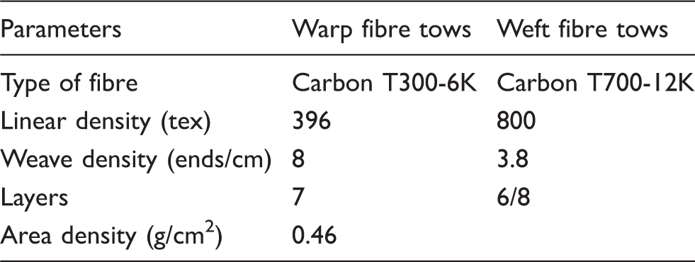
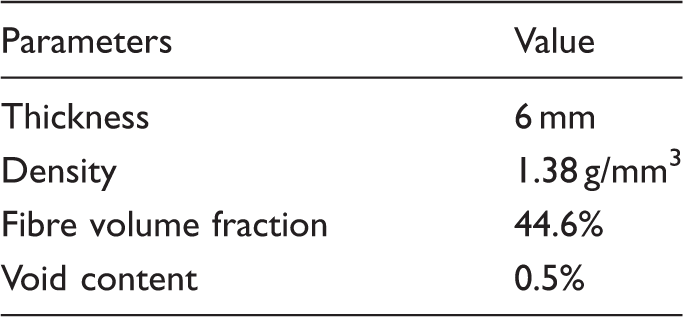
The 3-D angle interlock woven composite (3DAWC) was fabricated with JA-02 epoxy resin supplied by Changshu Jiafa Chemical Inc (China), using vacuum assisted resin transfer molding (VARTM) method. The composite was consolidated with the curing process: 90℃/2 h + 110℃/1 h + 130℃/4h. The specifications of 3-D angle interlock preform and composite (shown in Figure 1) are listed in Tables 1 and 2 respectively. The specimens were cut with 150 mm in length along the warp direction and with 25 mm in width along weft direction. To investigate the mechanical properties change of epoxy resin in the ageing process, resin casting was made and cut into 6 × 3 × 6 mm cubes.
Three-dimensional woven preform and composite: (a) three-dimensional angle interlock woven fabric; (b) three-dimensional angle interlock woven composite. Specifications of three-dimensional woven fabric. Note: T300 and T700 are two kinds of carbon fibre tows supplied by Toray Inc(Japan). 6K(12K) means there are about 6000(12,000) carbon fibres in a single fibre tow. Specifications of three-dimensional woven composite.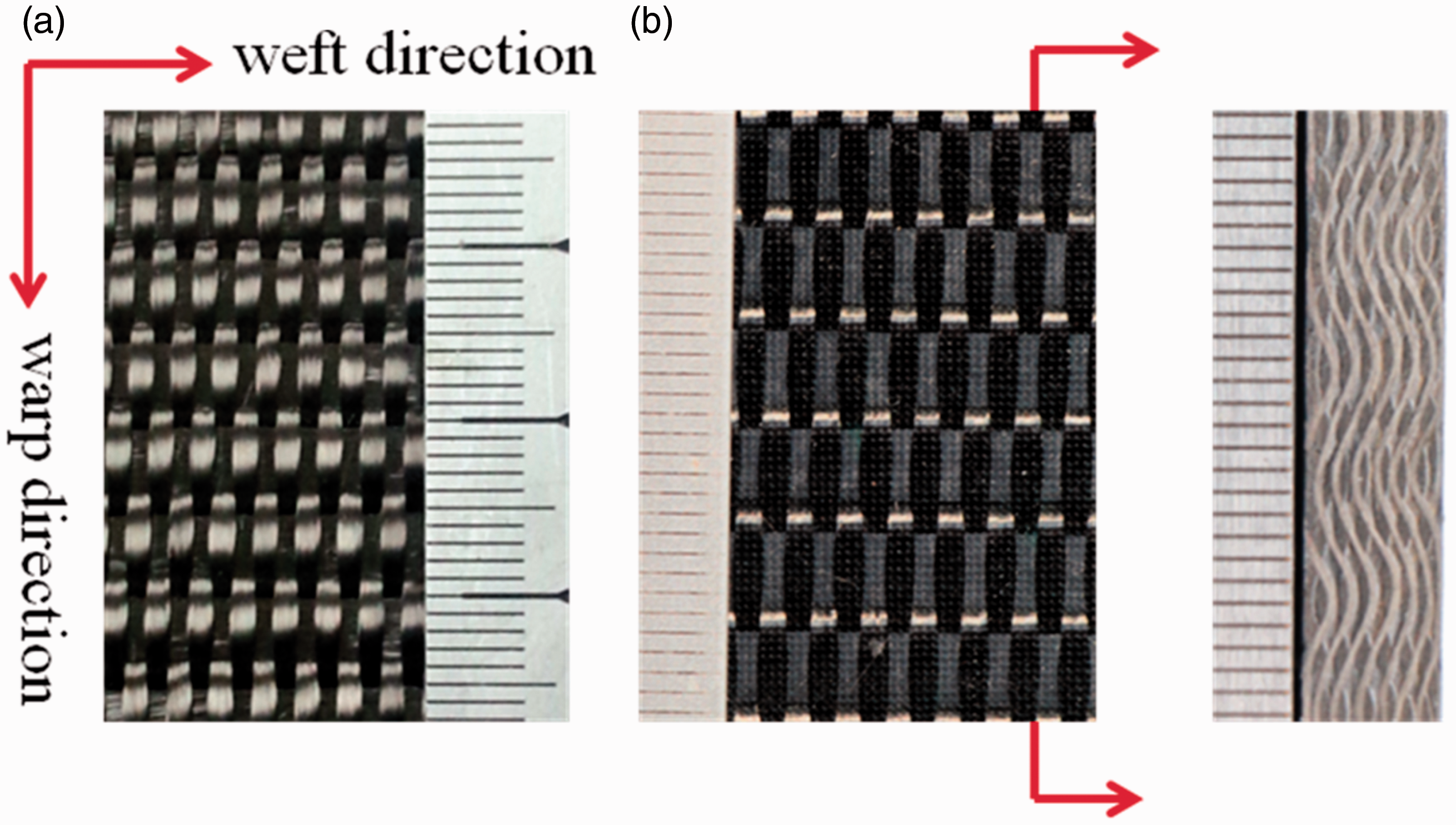
Accelerated ageing experiment
All testing coupons were pretreated in an oven for 1 h at 80℃ and then divided into five groups. One group (control group) was tested for comparing the ageing effect and the other groups were isothermally aged for 4, 8, 16 and 32 days at 180℃ in an air-circulating oven. All of the specimens were supported at two ends to ensure every surface received same heat.
2.3 Microscopy observation
Scanning electron microscopy (SEM) was used to observe surface morphologies of composites after thermal ageing to reveal the thermal ageing effect on composite coupons. Microscopy was also used to observe the fracture surface morphologies of both unaged and aged specimens after CAI testing.
Mechanical properties test
Compression tests on pure resins
To investigate the effect of thermal ageing on mechanical behaviours of the epoxy resins, compression tests were performed on MTS 810 material test system and the compressive speed was set to 2 mm/min. The tests were at room temperature (20℃). Three repeated experiments have been done and the average compressive behaviours were obtained.
Low velocity impact test
Low velocity impact properties of both the aged and the unaged 3DAWC were tested on Instron Dynatup 9250 impact tester (Figure 2). All specimens were tested at the incident rate of 0.696 m/s corresponding to the impact energy level of 3 J. The set up of test was similar to three point bending test in which a rectangular specimen was impacted in the middle while supported at the two ends. During all impact tests, a steel mass was attached to the steel impactor with a hemispherical tup of 12.7 mm diameter for a total weight of 12.4 kg. The test apparatus also incorporates a latching mechanism which catches the impactor after its initial impact so as to eliminate multiple impacts.
Photograph of Instron Dynatup 9250 impact tester.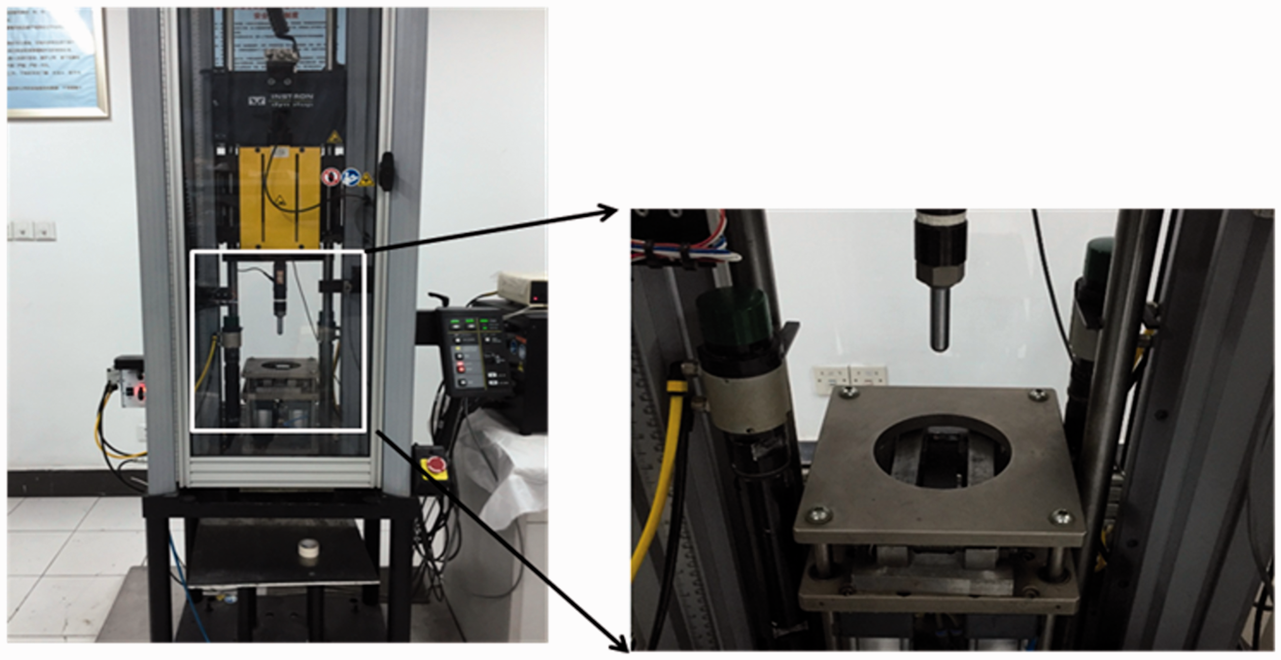
Compression tests after impact
To evaluate the residual strength of each composite after the impact tests, the samples were subjected to a quasi-static CAI. The residual strength tests of specimens were performed on MTS 810 material test system (Figure 3) and the compressive speed was set to 2 mm/min. The tests were at room temperature (20℃). Each sample includes three specimens and the average compressive behaviours were obtained.
In-plane compression test on MTS 810 material test system.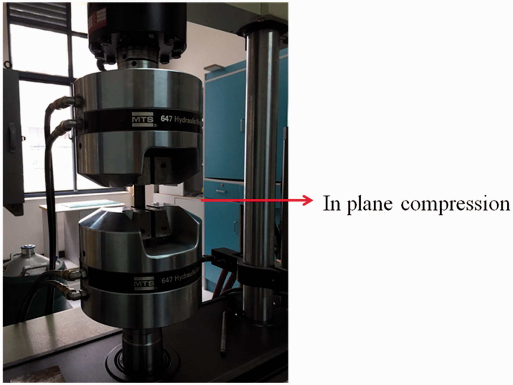
Finite element modelling
CAI testing model
Numerical simulation of CAI process was conducted using the commercial finite element analyses (FEA) software ABAQUS/CAE. The CAI testing model includes low-velocity-impact model and compression model as shown in Figure 4. The meso-structure model of 3-D angle-interlock woven composite was established on the basis of the spatial geometrical characteristic of yarns. Based on the symmetrical structure of the 3DAWC, only a half of the composite was modelled to save computing time. The model consisted of 596,160 solid elements, where 432,000 elements for the epoxy resin, 164,160 for the 3DAWF perform, 1596 for the impactor and 350 for the support plate. Eight-node hexahedral reduced integration elements (C3D8R) were selected to mesh the whole system. The impactor and support plate were defined as isotropic material which only undergone elastic deformation under the impact process. The carbon fibre tows were regarded as transversal isotropic elastic material. As they were impregnated with resin during the consolidation process, the mechanical properties of all fibre tows are obtained by the method of the bridging model.
25
The mechanical properties of carbon fibre tows were assumed to be unchanged during the ageing process due to its good thermal stability under the given ageing conditions.11,12 The mechanical behaviour changes of the epoxy resin were introduced into the model to calculate the CAI behaviours. It is assumed that the resin is an elastic-plastic solid obeying the J2-isotropic hardening plasticity theory with an associated flow rule and a von Mises yield criterion.
26
Finite element analyses model: (a) low velocity impact model; (b) compression model.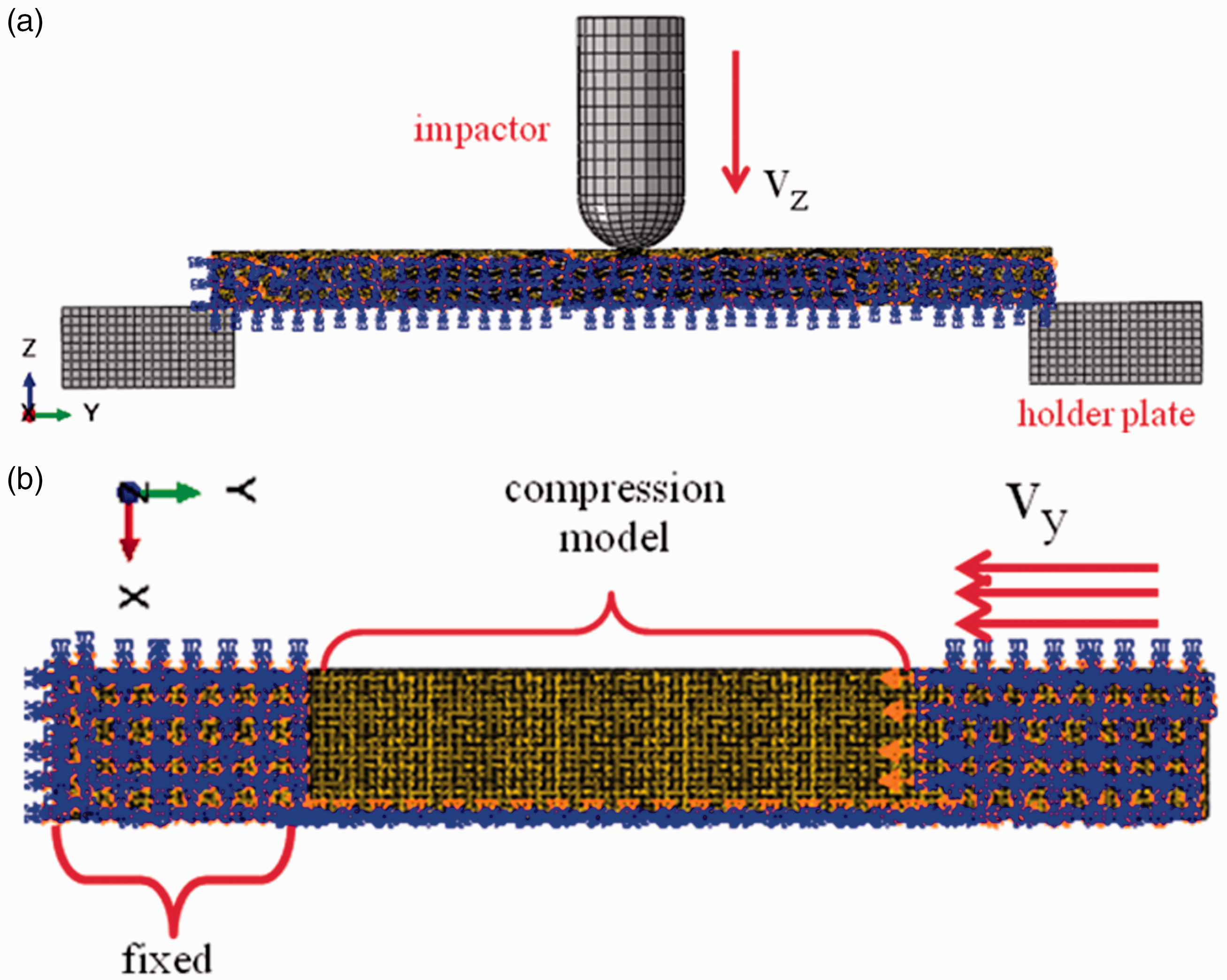
Damage criterion
3-D Hashin criterion for 3-D woven fabric reinforcement 27
Fibre tensile failure (
Fibre compressive failure (
Matrix tensile failure (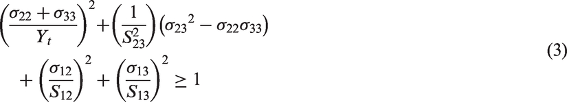
Matrix compressive failure (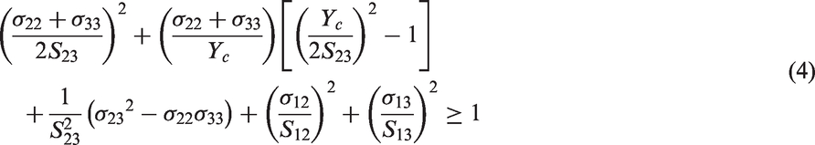
Ductile and shear criterion for resin28,29
Ductile criterion
The model assumes that the equivalent plastic strain at the onset of damage, 
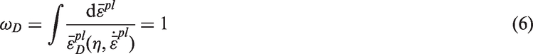
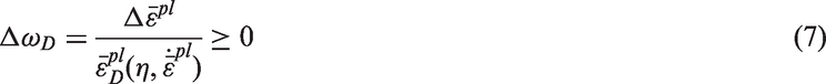
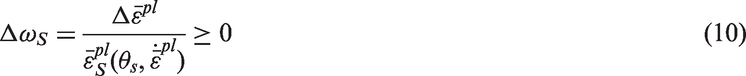
Shear criterion
The shear criterion is a phenomenological model for predicting the onset of damage due to shear band localisation. The model assumes that the equivalent plastic strain at the onset of damage, 
Here 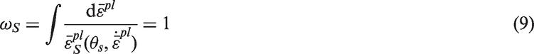
Interface damage criterion
Figure 5 shows the constitutive model of surface-based cohesive behaviour based on bilinear traction law,
30
relating the traction (t) and separation displacement (δ) between two adjacent faces. This model is consisted of three phases: linear elastic phase, damage initiate phase and damage evolution phase.
Bilinear cohesive constitutive law.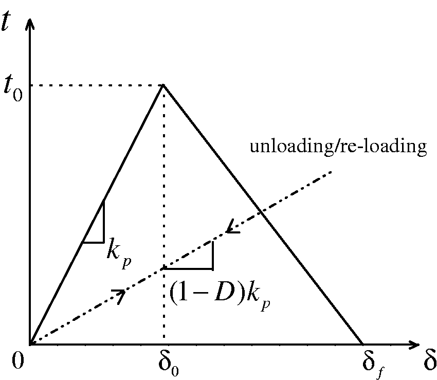
Linear elastic phase: the tractions across the interface increase linearly by increasing the separation displacement, with a prefixed slope (penalty stiffness 
Damage initiate phase: damage is assumed to initiate once the peak value t0 is reached.
Damage evolution phase: this phase is used to describe the rate of degradation of the interface stiffness once damage initiate. Benzeggagh–Kenane fracture criterion
31
was used to govern the damage evolution process. The damage variable D which can vary between 0 (undamaged interface case) and 1 (complete decohesion case) could be expressed as follows

There are different coefficients of thermal expansion (CTE) between the carbon fibre and the epoxy resin which resulted in the residual stress. The existence of residual stress led to the degradation of interface between fibre and matrix as ageing time continued. 16 Therefore, the interface properties specified for damage initiation and damage evolution would be poorer in the later stage of the ageing.
Results and discussions
Mechanical behaviours
Compression behaviour of the epoxy resin
Compressive behaviours of epoxy resin at different ageing days.
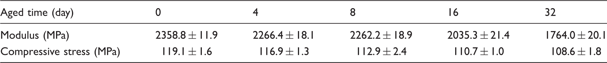
Accelerated thermal ageing effect on compression behaviours of epoxy resin.
Low-velocity impact properties of 3DAWC
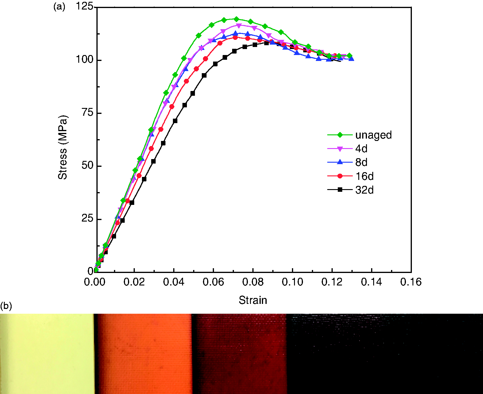
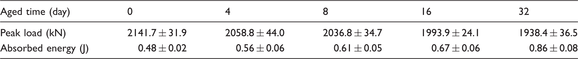
Typical load-time curves and energy-time curves of composites aged for different days are given in Figure 7(a) and (b) respectively to compare the effect of thermal ageing on strength and energy dissipation. The detail values of the peak load and absorbed energy are listed in Table 4. Peak load decreases gradually along with ageing time. Besides drop of maximum force, curve appearance also changes with the extension of accelerated aging time. For the longer aged composites, the curve shape changes: the loading time is shorter than the unloading time. As a result, total impact time increases continuously with ageing time. The absorbed energy is the energy absorbed by the composite in form of damage and friction between the impactor and the composite. The absorbed energy increased continuously with the ageing time which indicates that more damage was caused by impact loading although no macro crack occurs.
Low velocity impact properties of three-dimensional woven composite: (a) experimental results of load–time curves of composite coupons with different ageing time; (b) energy–time curves of composite coupons with different ageing time. Low velocity impact behaviours of three-dimensional woven composites at different ageing days.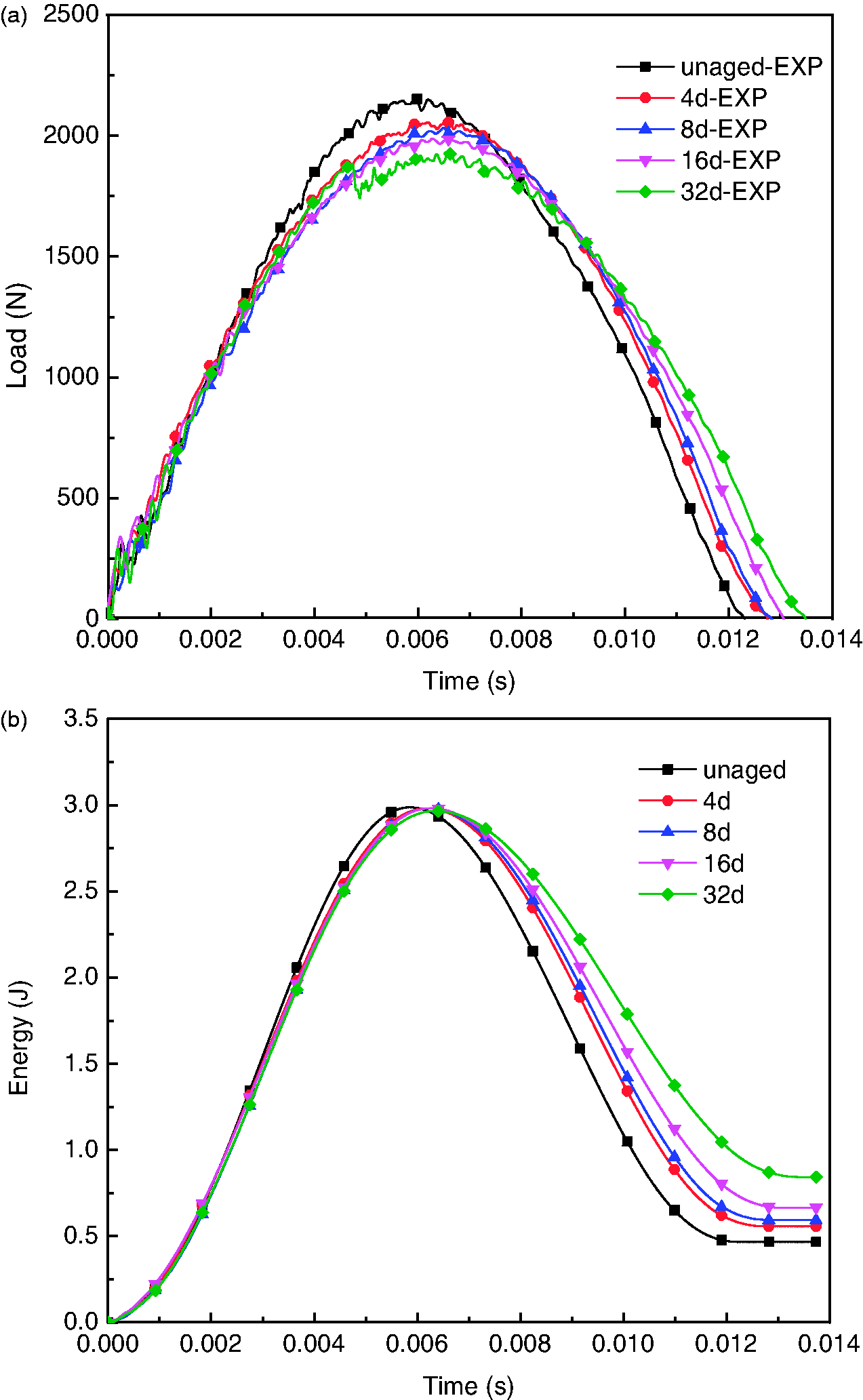
CAI behaviours of 3DAWC
Compression after impact behaviours of three-dimensional woven composites at different ageing days.
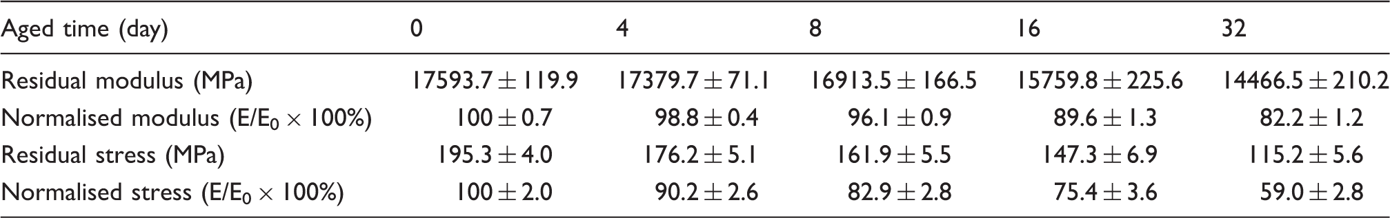
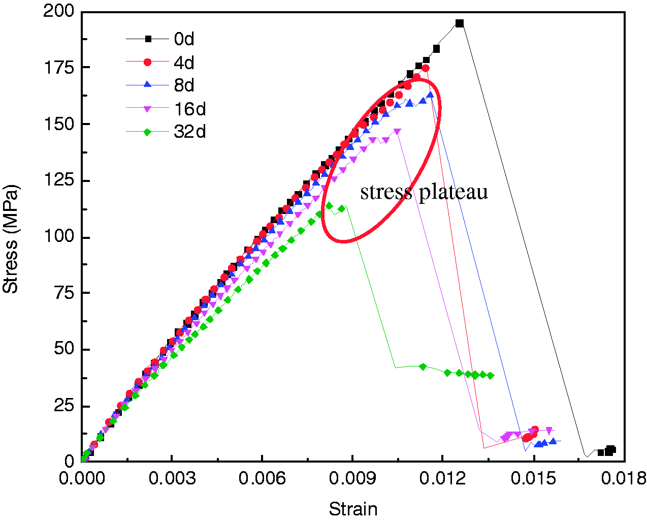
Accelerated thermal ageing effect on compression after impact behaviours of three-dimensional interlock woven composites.
Surface morphology observation
Surface morphology observation was conducted to find out the effect of thermal ageing on failure mechanisms of composites. Figure 9(a) to (e) shows the morphologies of the free surfaces (perpendicular to the weft yarns and exposure to hot air) as ageing time increases. The spontaneous micro cracks initiate at the fibre/matrix interface and propagate to the nearby resin rich area due to the brittleness of epoxy resin as ageing continues. These cracks provide additional surfaces and pathways for oxygen delivery which cause the aggravation of ageing. In loading process, the microcracks grow under the action of loads leading to premature failure of composites.
Scanning electron microscopy observations of three-dimensional composite coupons showing the initiation and propagation of spontaneous crack along with ageing time.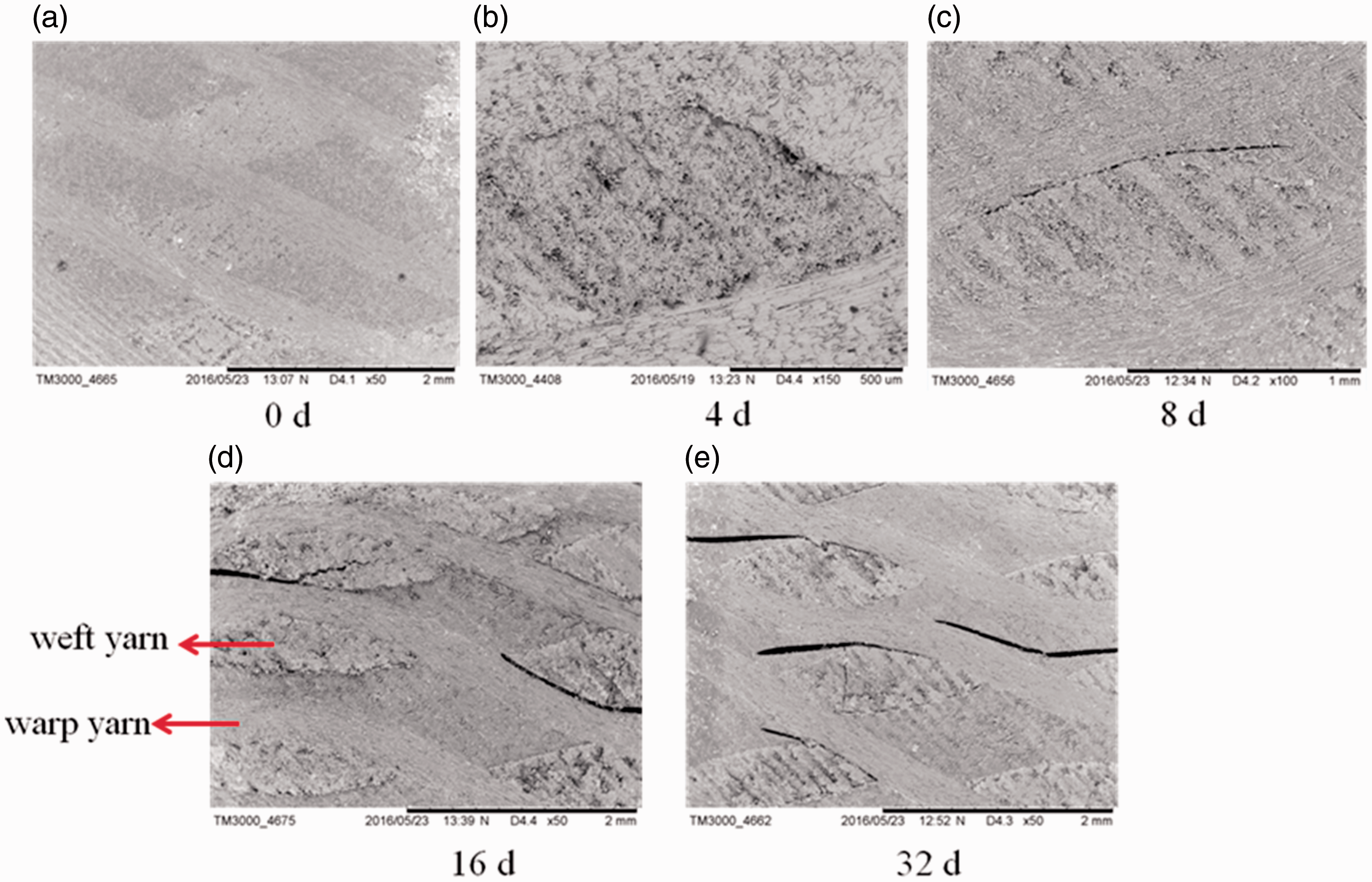
The thermal ageing effects on fracture surfaces of the specimens were depicted in Figure 10(a) to (d). It can be found that the crack path of aged specimen is different from the one in the unaged specimen. Cracks propagate along yarn-matrix interface after ageing. It is possible once the yarn/matrix interface is weakened to such extent that it becomes the favoured crack path. But for the unaged specimen, crack path was irregular, it might run through the fibre tows and more matrix was caused. Figure 10(d) shows the fracture surface morphologies of the unaged specimen and the 32 days aged specimen. It is noted that for the unaged specimen, the fibres are still adhered by matrix and the interface is bonded finely. Matrix cracking is the primary failure mechanism consequently. However, after long time exposure to high temperature, little resin is attached to the fabric in the fracture surface which reveals a loss of adhesion integrity at the yarn/polymer interface. This phenomenon suggests that interface damage becomes the main failure mode after long time ageing.
Photos of failed specimens after the compression after impact tests: (a) side view; (b) front view; (c) microscopic photo of failed specimens: unaged & 32 days aged specimens; (d) fracture surface morphologies of unaged specimen & 32 days aged specimen.
Stress distribution and failure evolution
The FEA model was used to simulate the CAI process. Figures 11 and 12 illustrate a good agreement between experimental and FEA results.
Load-time curves obtained by finite element analyses model: (a) finite element analyses results of load–time curves with different ageing times; (b) Comparison between finite element analyses and experimental results of unaged specimen. Load–time curves obtained by finite element analyses model: (a) finite element analyses results of stress–strain curves with different ageing times; (b) comparison between finite element analyses and experimental results of unaged specimen; (c) comparison between finite element analyses and experimental results of 32 days aged specimen; (d) four representative moments in loading process chosen to describe the stress transfer process.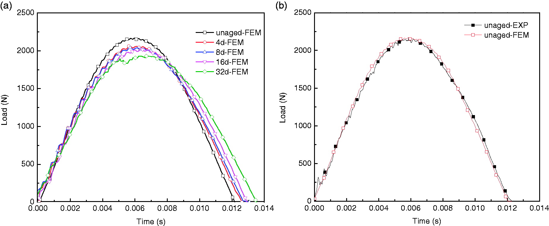
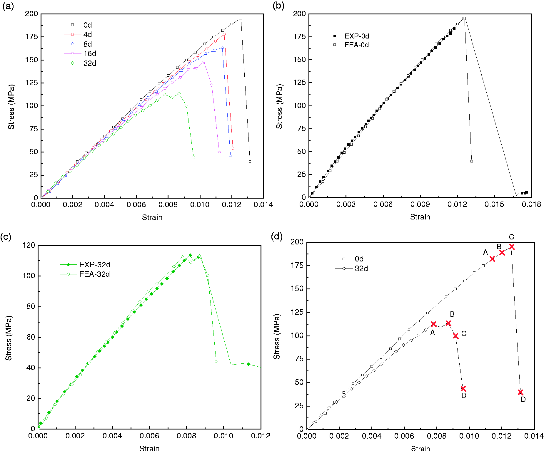
Figure 13 shows surface damage morphology of the FEA models and microscopy images near impact point after low velocity impact. Interface crack propagation can be found in the upper side of 32 days aged composite, while no obvious damage induced by impact loading can be observed for composites aged for less days. It indicates that the impact resistance of composite decreases as ageing time continues.
Interface damage morphologies of side view in finite element model and microscopy images.
Figures 14 and 15 show the stress distributions evolution on 3DAWF preform and epoxy resin after the exposure at 180℃ for different days. Four representative moments (Figure 12(d)) in loading process were chosen to describe the stress transfer process. As low velocity impact induces interface damage within a region near impact point. The transmissibility of stress is impeded by the degraded interface. And this will cause stress concentrations in matrix as shown in Figure 15. Meanwhile, the failure of interface leads to stress reduction in the neighboring yarns.
Stress distribution of three-dimensional woven fabric aged after different days at 180 C. Stress distribution of epoxy resin aged after different days at 180 C.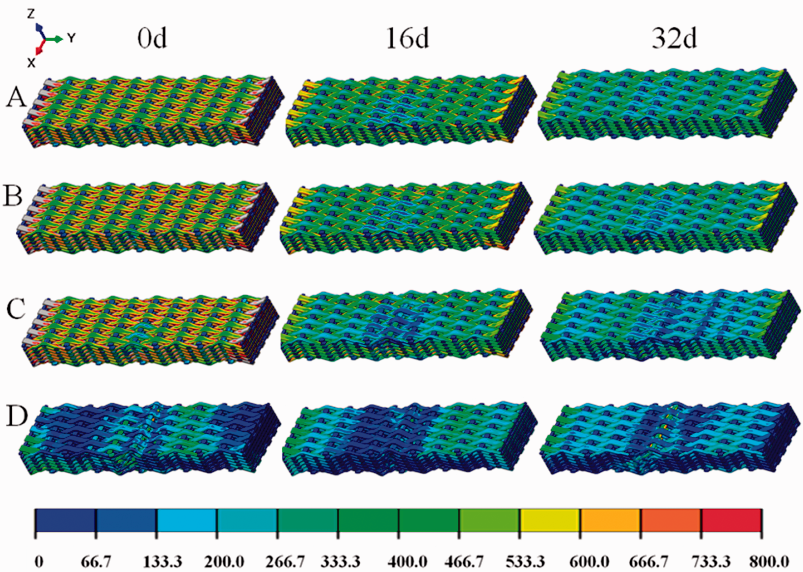
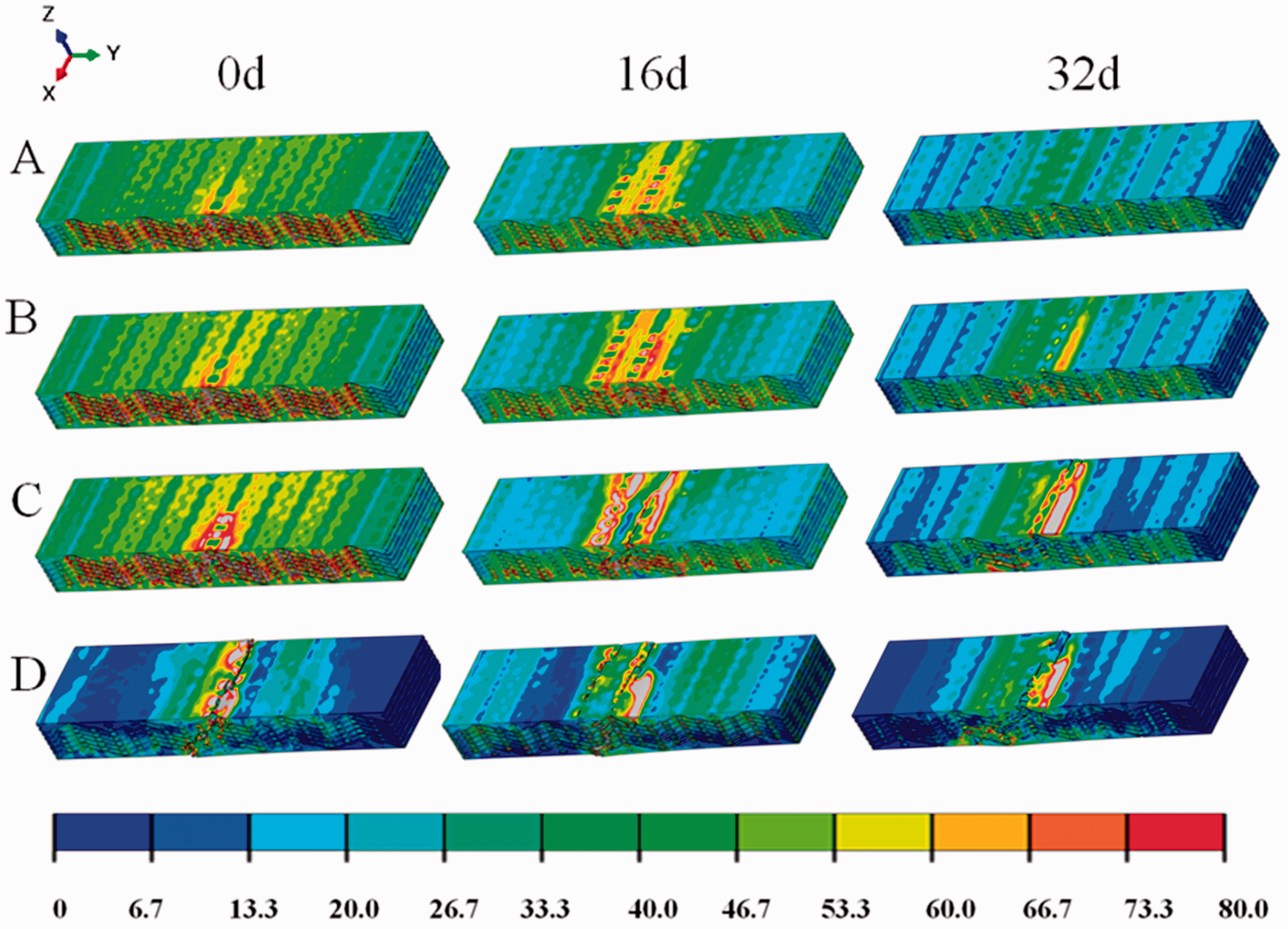
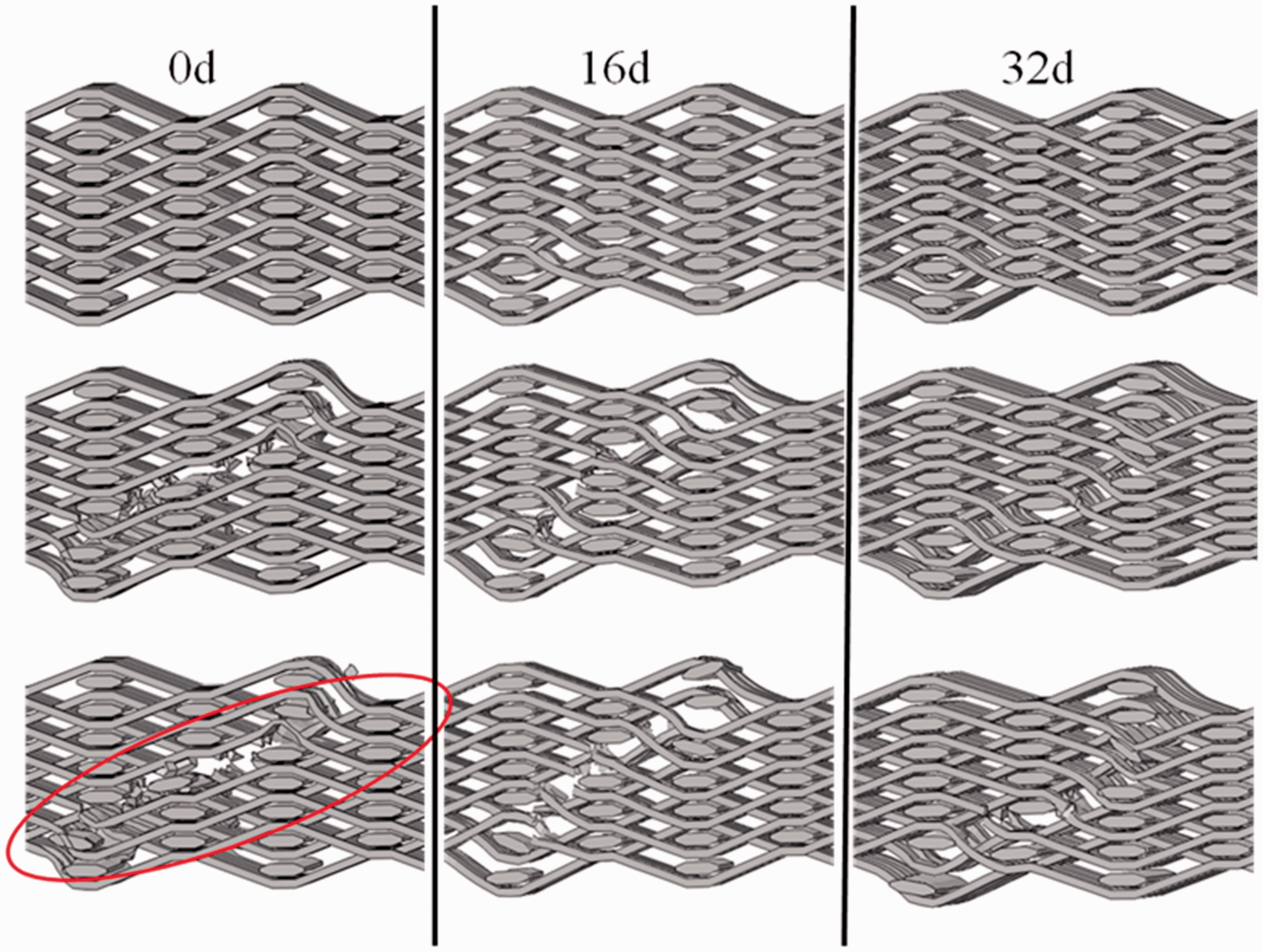
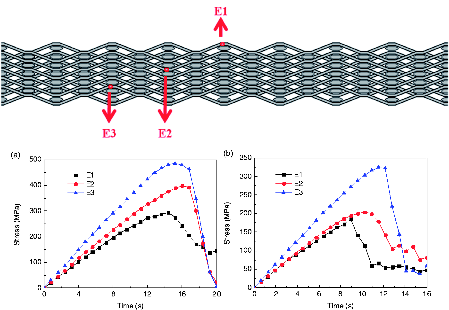
Figure 16 compares the interface damage evolution in the failure process of composites ageing for different days. The grey scale represents the damage variable D in Section ‘Damage criterion’. It can be seen that no significant interface damage occurs in the unaged specimen until final failure. However, the fibre/epoxy interface was seriously damaged with the increase of ageing time. Interface damage evolves gradually along with crack propagation leading to ultimate failure of specimen. It indicates interface damage becomes the main failure mode after long time thermal ageing. Damage evolution in 3-D woven fabric preform is depicted in Figure 17. Yarn breakages almost take place simultaneously in unaged preform. While after ageing, yarns fail progressively which seems consistent with interface damage evolution. Figure 18 shows stress curves for elements E1, E2 and E3 in both the unaged specimen and 32 days aged specimen respectively. Compared with the unaged specimen, the elements in aged specimen fail one by one as depicted in the Figure 17. Taking the photograph of the 3-D woven composite after compression, it was found that there was a good agreement between experimental and FEM results which were compared in Figure 19. Both experiment and FEM results depict the rough fracture morphologies in the unaged specimen due to more matrix crack and the smooth fracture surface of aged specimen resulting from severe interface damage.
Damage evolution of the interface aged after different days at 180 C. Fracture process of three-dimensional woven fabric aged after different days at 180 C. Stress curve for three elements in warp yarns: (a) unaged; (b) aged for 32 days. Damage morphologies in finite element analyses model versus experiment: (a) front view; (b) side view; (c) rough fracture surface in unaged specimen caused by matrix crack; (d) smooth fracture surface in 32 days aged specimen induced by interface damage.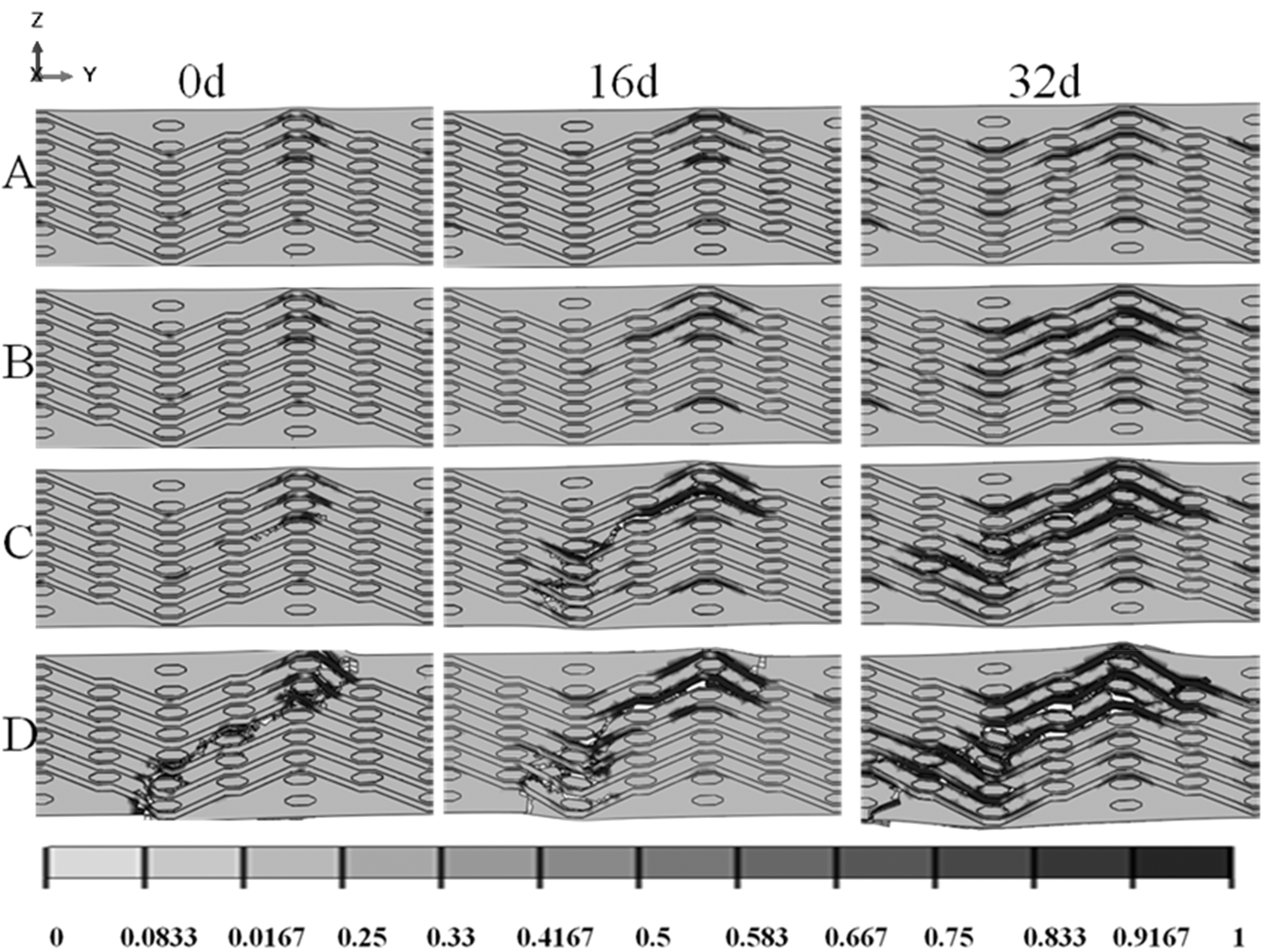

Conclusions
This investigation aims at illustrating thermal ageing degradation mechanisms on the CAI properties of 3DAWCs in both experimental and FEA methods. The specimens have been exposed to air for 4, 8, 16 and 32 days at 180℃. The FEA model was established at meso structure level to simulate the failure evolution before and after ageing. The following conclusions have been obtained:
Thermal ageing was shown to have remarkable influence on CAI properties. Residual stress declined greatly along with ageing time. The retention rate of CAI stress after ageing for 32 days is approximately 60% compared to that of un-aged one. The fracture morphologies indicate the failure of the unaged specimen was dominated by the epoxy resin while it transformed to interface damage after ageing. To insure the integrity of the composites long time operated at high temperature environment, the interface strengthening is essential. The FEA method was used to trace damage evolution until the final failure. The unaged sample exhibits a brittle fracture mode. While after long time ageing, the sample shows a progressive failure mode. The variation from a brittle failure to a progressive failure model might be account for the stress plateau occurred in stress–strain curve.
Footnotes
Declaration of Conflicting Interests
The author(s) declared no potential conflicts of interest with respect to the research, authorship and/or publication of this article.
Funding
The author(s) disclosed receipt of the following financial support for the research, authorship, and/or publication of this article: The authors acknowledge the financial supports from the Chang Jiang Scholars Program and National Science Foundation of China (Grant Number 11572085 and 51675095). The financial supports from Foundation for the Fok Ying-Tong Education Foundation (Grant No. 141070), Shu-Guang project (Grant No. 14SG31) supported by Shanghai Municipal Education Commission and Shanghai Education Development Foundation, the Fundamental Research Funds for the Central Universities of China and DHU Distinguished Young Professor Program are also gratefully acknowledged.