






Abstract
An alternative route for producing aluminium matrix reinforced with continuous carbon fibres is proposed in this paper. On the one hand, liquid aluminium does not wet carbon; on the other hand, however, the two form a reactive system leading to carbide formation. A novel way to obtain continuous carbon fibre-reinforced aluminium was investigated, using spark plasma sintering with aluminium foils as raw material. Sintering parameters were adjusted to achieve the effective welding of aluminium foils and penetration of the metal between the filaments. A quality assessment of the fibre/aluminium coupling is presented. Interfaces were then investigated by scanning electron microscopy, transmission electron microscopy and energy-dispersive ray spectroscopy. An effective cohesion of fibres with the matrix was shown. The manageable fibre positioning could result in unidirectional architecture and reinforcement rate should be handled through foil thickness and yarn properties. Using tensile tests, cohesion between aluminium and carbon fibres can be quantified.
Introduction
Aluminium matrix composite materials (AMCs) represent tremendous potential for many industrial applications, particularly for heat sink. An aluminium matrix reinforced by highly thermal conductive continuous carbon fibres represents a high potential for thermal applications. Over the last decades, many processing routes have been explored to develop AMCs, both in liquid and solid form.1,2
However, coupling liquid aluminium and carbon fibre can be difficult, due to their incompatibility. For example, a really low wetting of carbon by liquid aluminium3,4 and its chemical reactivity can lead to the formation of aluminium carbide Al4C3 which is harmful to the properties of the material.5–7 Many studies have tried to find solutions to these problems. These include the use of ceramic or metal fibre coatings.8,9 Metallic coatings mainly of nickel or copper are used to improve the wettability of fibres by aluminium.10,11 These coatings can be obtained through electrolytic methods, with current or by electroless techniques.12,13 Other techniques consist on the chemical activation of wetting by deposits of fluorinated salts K2ZrF614 or K2TiF615,16 or even processes involving the use of infiltration by ultrasound or by means of a pressurized chamber.4,17,18
The use of the solid processing route is another alternative for developing carbon fibre-reinforced AMCs. These processes consist of maintaining a discontinuous material under pressure at a temperature below its melting temperature. This solution eliminates wetting problems. In addition, the diffusion mechanisms are largely slowed down, as the carbon can be considered insoluble in solid aluminium. 19
In order to employ continuous reinforced metal matrix composites (MMCs) by means of powder metallurgy, it is essential to be able to control the placing of the reinforcement in the matrix. By using slurry20,21 or a continuous titanium powder pre-deposition technique on silicon carbide (SiC) filaments that have been positioned before being sintered,22,23 MMCs can be produced. However, as the diameter of the carbon filaments is more than 10 times smaller than that of the SiC filaments, this process proves to be unsuitable for obtaining sufficient fibre volume fraction.
The use of sheets instead of powders may in some cases be a suitable alternative as this will considerably restrict fibre swimming24,25 during implementation. This technique is used to produce titanium matrix composites reinforced with SiC filaments. 26
In the case of aluminium, however, the presence of a thin layer of alumina makes penetration difficult and it is essential that it is disrupted during the process to ensure a good penetration of the aluminium. 27 To encourage this disruption and promote good consolidation, some authors have suggested initially using a powder with an irregular morphology, 28 or sintering in a nitrogen atmosphere, 29 or adding magnesium to the aluminium powder. 30 However, as sheets have a flat surface, they are not sufficiently able to ensure that this disintegration takes place during conventional hot compression.
Spark plasma sintering (SPS) is a technique that has proved effective for quickly and easily sintering a large number of materials, even those which are difficult to sinter, and obtaining new microstructures at room temperature. 31 It differs from traditional hot compression as its heating mode is by pulse current directly through the mold and the sample if it is a conductor. With this technique, very rapid heating rates can be achieved (up to several 100 K/min), notably making it possible to obtain vitreous structures. 32 In addition, there are many mechanisms at the interfaces associated with the strong SPS currents that can activate sintering more effectively than the traditional hot compression processes.33–37 Al-Cf composite materials with particulate reinforcement38,39 or with discontinuous fibres have already been obtained by powder metallurgy by mixing chopped fibres with the powder before hot compression by SPS. 40 Continuous fibre-reinforced aluminium has also been achieved by SPS by sinking fibres into an ethanol suspension solution before sintering. 41 Thus, SPS can be a solution for sintering aluminium while doing away with the layer of oxide.
Until now, its use has mostly been restricted to the sintering of powders, and the use of metallic foils has only been investigated within this process in a few cases. 42 Hence, a new way to manufacture aluminium matrix composite reinforced by continuous carbon fibres using the fibre–foil technique processed by SPS was investigated. The application only aims at providing a good local bonding between fibre and aluminium to ensure a thermal conductive interface. The objective is not to obtain good mechanical properties for the composite material.
After carrying out studies to adapt the sintering parameters (temperature, pressure and time) in order to obtain well penetrated carbon fibres, qualitative and chemical analyses of the interface are presented.
Experimental setup and starting material
Pitch-based carbon fibres (YS-80 A, Nippon Graphite Fibre) with high-modulus and high thermal conductivity (800 GPa; 320 W/(m.K) – manufacturer’s data) and made up of 3 k filaments were cut into 10 mm lengths then placed between 25 µm-thick sheets of aluminium 1050 A (EN 573-1, Goodfellow).
There are different techniques for removing the seizing from carbon fibres;4,5,17,43 this has to be done to avoid any fibre–matrix interface contamination by polymer species. After carrying out a thermogravimetric analysis on our fibres, a 30-min finish removal at 400℃ was put in place. There is also a preparation of the surface of the aluminium foils before the SPS: degreasing with deionized water/pickling 10 s in a NaOH solution – 4 g/L at 50℃ with movement/several prolonged rinses with deionized water/drying in an oven.
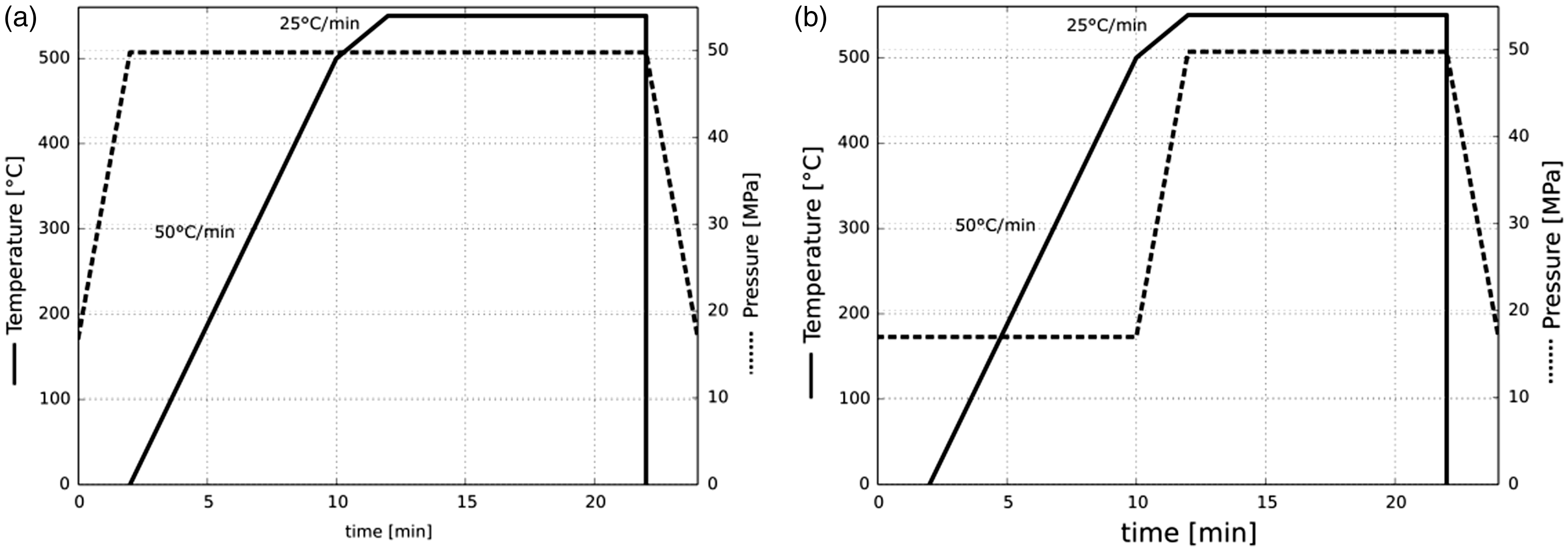
The different stacks of sheets and fibres were placed in a graphite mold (Graphitech) comprising a floating matrix of 15 mm in diameter and two pistons (Figure 1) then placed between the two electrodes of the SPS equipment (Dr. Sinter LAB (SPS-515), SPS Syntex Inc.). Sintering was carried out in a vacuum. Uniaxial pressure was applied gradually until reaching 50 MPa after two minutes. The heating sequence was 12:2, a heating rate of 50℃/min up to a temperature level of 500℃, then 25℃/min for the last 50° to reduce overshoot. The 12:2 pulse used in the study is the pulse condition recommended by the manufacturer SPS Syntex Inc: the first number corresponds to the time ON and the second to the time OFF. The current pulses are ON: OFF sequences of 3 ms. In addition, a minimal force of 3.3 kN (i.e. pressure of about 17 MPa for our setup) was applied before beginning the experiments to ensure adequate electrical contact. Temperature was measured and controlled by a type K thermocouple placed 3 mm from the outer surface of the matrix. At the end of the sintering process, the electric current was turned off and the sample cooled in a vacuum in the mold. The sample was kept separate from the different parts of the mold by sheets of graphite (papyex) to prevent them from sticking.
Experimental setup (SPS). SPS: spark plasma sintering.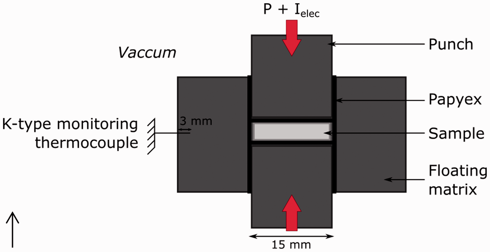
After cutting, polishing and lastly ionic abrasion, the resulting samples were characterized by optical microscope (Keyence), scanning electronic microscope (SEM, Hitachi S-3000 N), electron dispersion spectroscopy (EDS, Bruker XFlash 6l10 or Oxford Instrument Xmax) and transmission electron microscopy (TEM, JEOL JEM-ARM 200 F).
Results and comments
Adapting experimental parameters
Tests without reinforcement
Before processing composite samples, it was necessary to ensure that SPS was effectively able to bond aluminium foils and determine the sintering temperature for further experiments. Sintering trials were carried out on a stack of simple sheets (without reinforcement) comprising two 500 µm sheets between which were placed three 25 µm sheets (Figure 2). Different sintering temperatures were tested (500, 550 and 575℃) with isothermal hold for 10 min at a pressure of 50 MPa.
Cross-section diagram of sheet stack for adjustment of sintering temperature.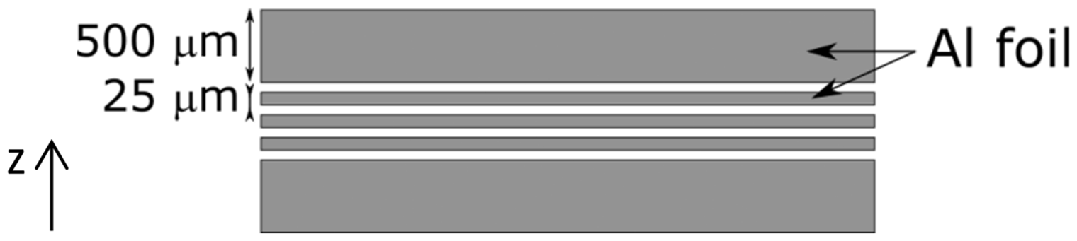
The 575℃ test caused the aluminium to melt, although the temperature measured by the thermocouple was lower than the melting point of aluminium. Many numerical and experimental studies have indeed reported strong temperature gradients in the SPS assembly.44–47 When dealing with a conductive material, the current passes directly into the sample, which therefore heats up by the Joule effect. Thus, the temperature in and around the sample is higher than at the point used as the temperature control point. The temperature measured by the thermocouple placed 1 mm from the sample did indeed show that there can be a difference in temperature of 80℃ between this point and the control thermocouple for a control temperature of 550℃, which confirms the results found in the literature.
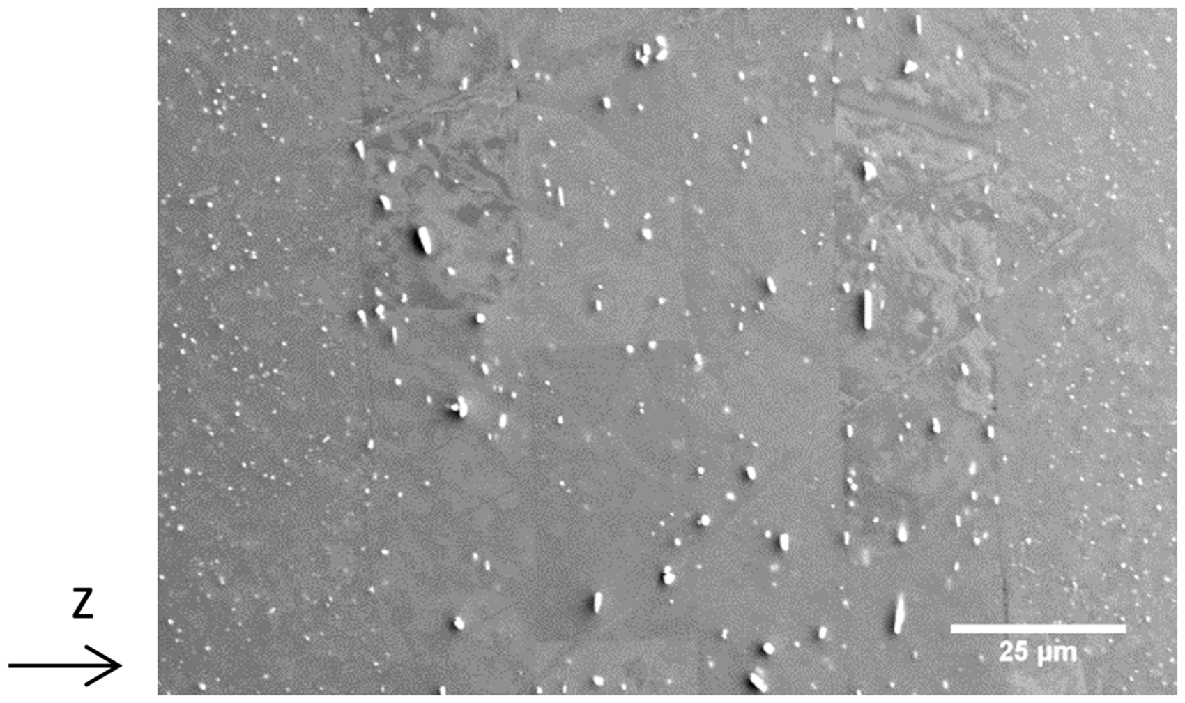
Samples obtained for temperatures of 500 and 550℃ appeared to be well consolidated. The 500℃ sample was prepared for microscopic examination and showed delamination along its entire length (Figure 3). The samples obtained at 550℃ were well consolidated, although the interface between the different sheets remained visible under the SEM (Figure 4). We also noted the presence in the aluminium of intermetallic compounds appearing white, which under EDS analysis proved to contain iron, the common main additional element present in 1050 aluminium.
Cross section of a sample of aluminium alone produced at 500℃ (optical microscope). Demonstrating bonds between sheets (SEM). SEM: scanning electronic microscope.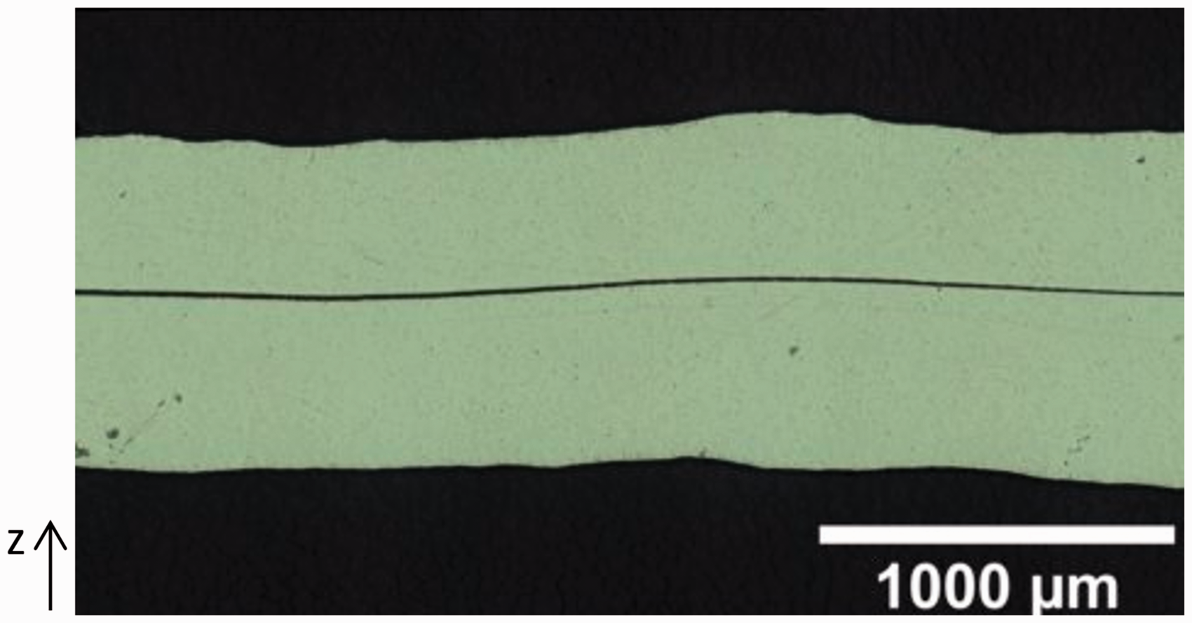
Experiments with reinforcement
After these encouraging results, we moved on to composite samples, retaining the sintering temperature at 550℃. Carbon fibres were introduced manually between each of the 25 µm-thick sheets, in the same direction (Figure 5). The filaments were laid out widthways in order to reduce the number of filaments that made up the thickness of the fibre and facilitate infiltration by the aluminium. This step was carried out by hand, resulting in a non-uniform distribution of filaments within the consecutive layers. Two configurations of pressure application and temperature were studied, with pressure applied either at the beginning before heating or when hot just before the sintering stage (Figure 6).
Diagram of composite stack to study the influence of time. Different pressure and temperature profiles during sintering: (a) pressure applied on the specimen at room temperature; (b) pressure applied on the specimen from 500℃.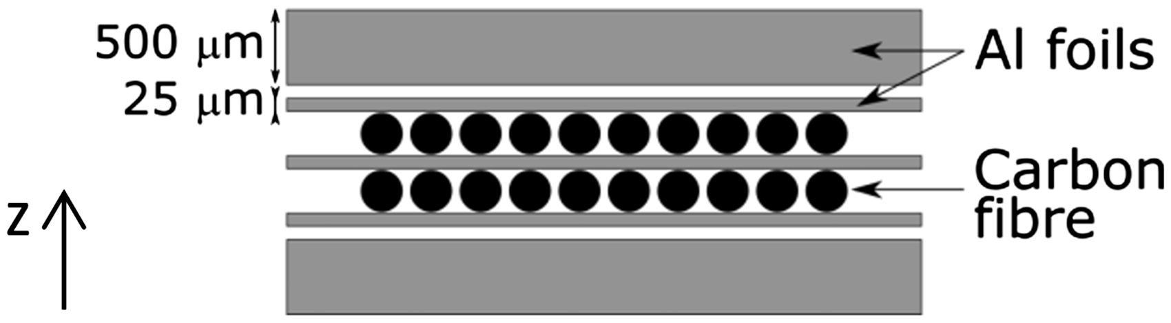
Pressure application
Observations of polished cross sections show that the fibres retained their original position, thus the structure of the material can be compared to that of a multilayer material (Figures 7 and 8). When pressure is applied at room temperature, the filaments are mostly compacted and partially crushed, forming a continuous mass of carbon that the aluminium is unable to infiltrate (Figure 7). Around the edges, however, the filaments in contact with the aluminium are well embedded in the metal. When the thickness of the fibre is a single filament, these filaments are completely infiltrated by the aluminium.
Cross section of a sample produced at 550℃ with pressure applied on the specimen at room temperature (SEM). SEM: scanning electronic microscope. Cross section of a sample produced at 550℃ with pressure applied on the specimen from 500℃ and holding time of 10 mn (SEM). SEM: scanning electronic microscope.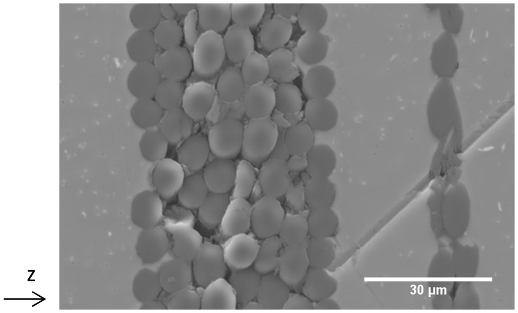
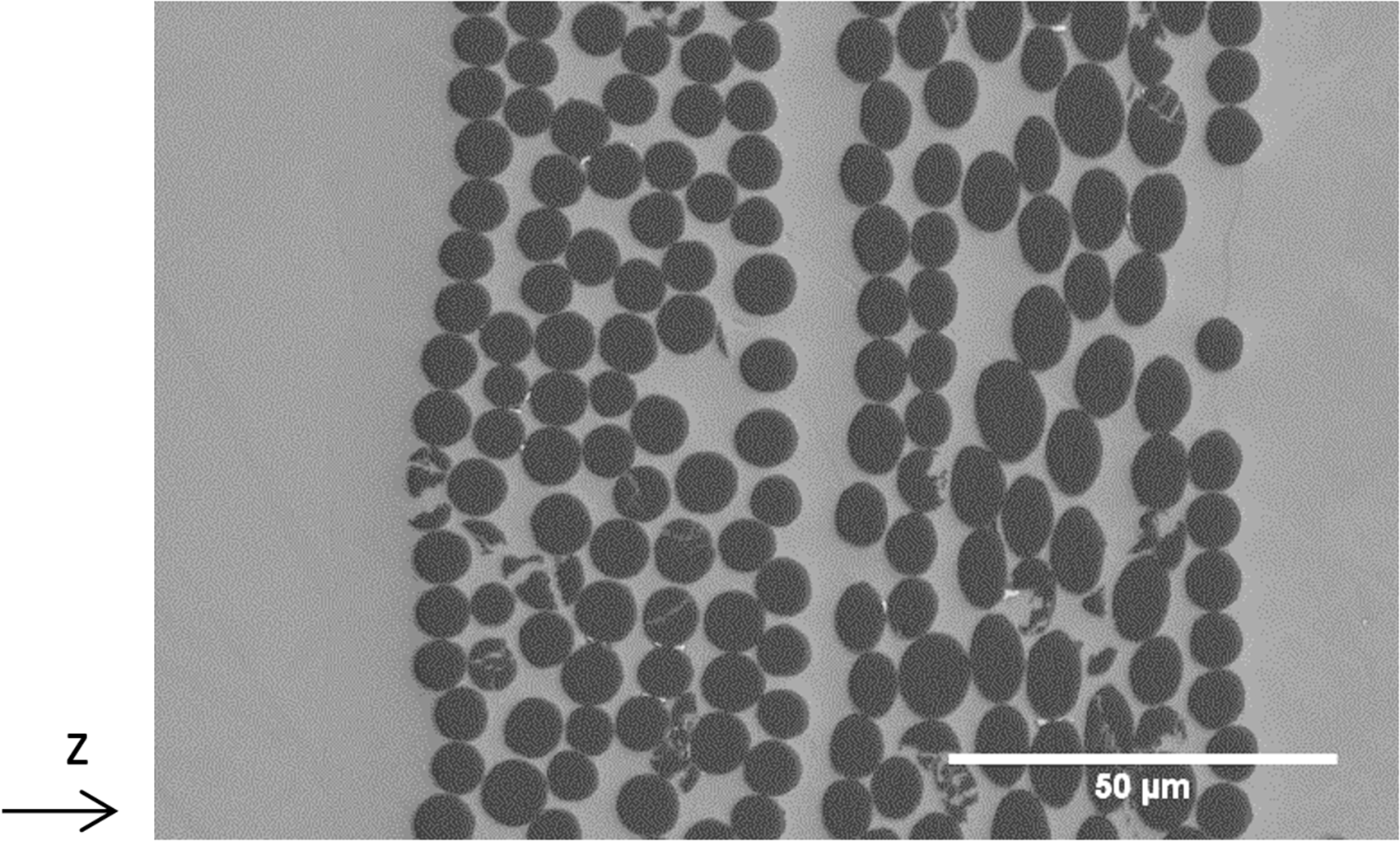
The samples produced by applying hot compression included fibres that were perfectly infiltrated by the aluminium (Figure 8). When pressure is applied as the temperature reaches 500℃, the aluminium penetrates the fibre, which shows no signs of crushing. At this temperature, the viscosity of the aluminium state is assumed to be sufficiently low to enable it to deform between the filaments without crushing the fibre: each filament is then completely surrounded by aluminium, even when the filaments are very close together, with spacing of less than 1 µm. Nevertheless, some damaged filaments were observed.
Isothermal holding time
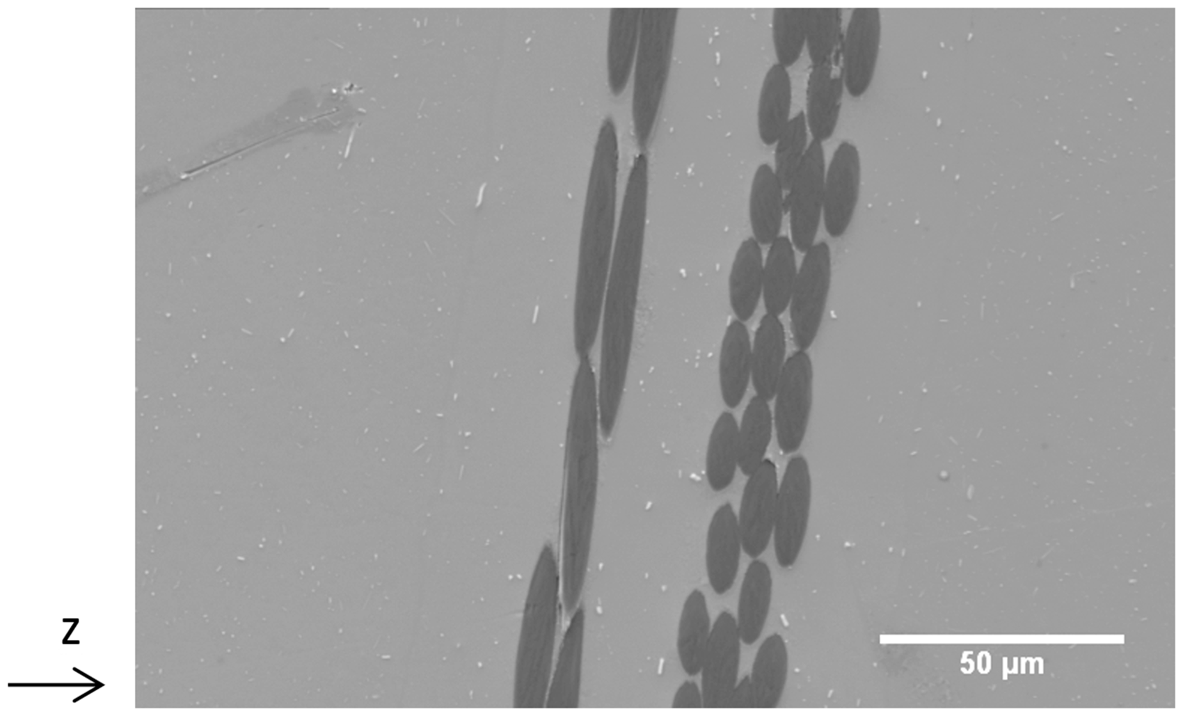
Samples were produced by being held at 550℃ for 5, 10 and 20 min with hot pressure applied. A holding time of five minutes proved insufficient to obtain a satisfactory result (Figure 9): the sample revealed considerable defects linked with infiltration, cohesion and filament scouring. After a 10 min holding time (Figure 8), the infiltration we obtained was very satisfactory and the samples showed no fibre scouring and few areas of debonding. The results are similar after a holding time of 20 min (Figure 10). For the continuation of the study, the holding time is equal to 10 min.
Debonding between filaments and aluminum in a cross-section of a sample produced at 550℃ with pressure applied on the specimen from 500℃ and holding time of 5 mn (SEM). SEM: scanning electronic microscope. Cross section of a sample produced at 550℃ with pressure applied on the specimen from 500℃ and holding time of 20 mn (SEM). SEM: scanning electronic microscope.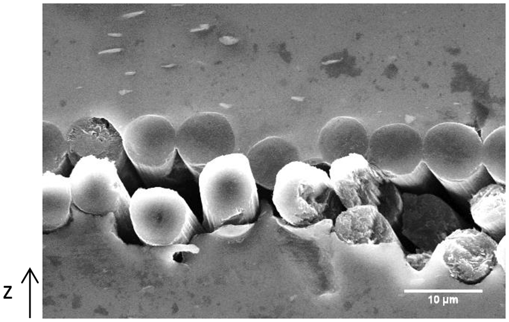
Summary
Early studies to develop a carbon fibre-reinforced aluminium matrix composite by the SPS process from aluminium sheets led to the choice of applying uniaxial pressure of 50 MPa at 500℃ immediately before 10 min sintering at 550℃. These experimental parameters gave well-infiltrated fibres which maintained their position and had limited damage. These results were reassuring with the view to obtain full composite samples.
Implementing a multilayer composite
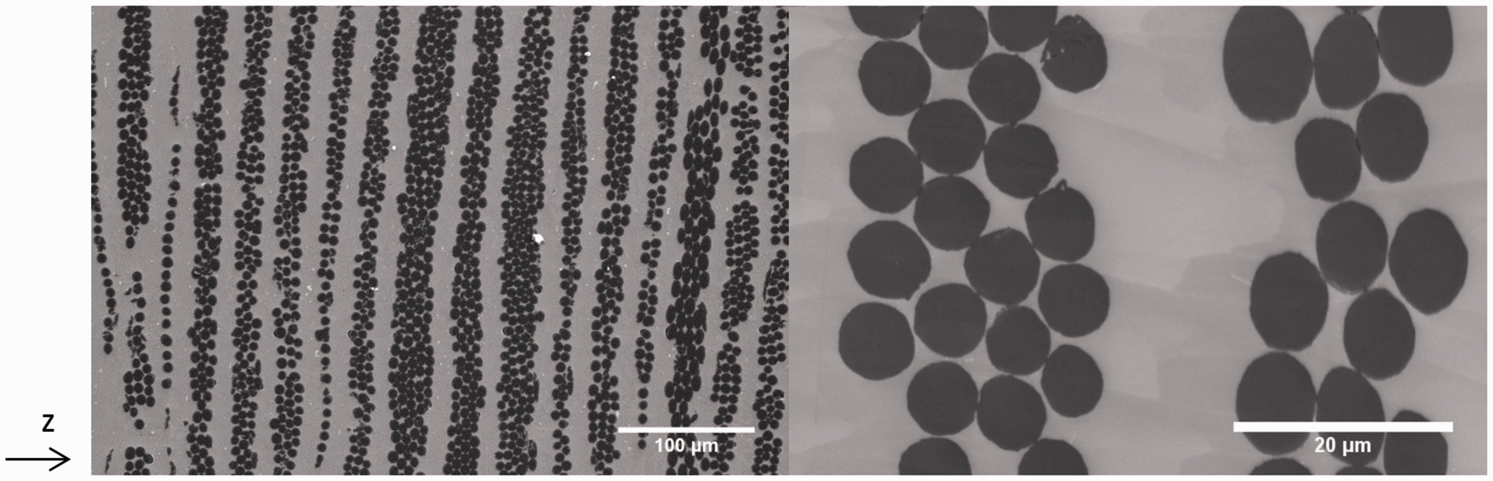
Samples were developed comprising a stack alternating only thin sheets and carbon fibres, giving a sample containing 20 layers of carbon fibres (Figure 11). Our observations suggest that the fibres are very well infiltrated, with position and orientation conserved despite alignment defects due to being put in place manually (Figure 12). In addition, filament density is not uniform across the width of the sample for the same fibre. The volume fraction of carbon fibres is estimated from image analyses to be around 40% and may be higher, thus changing the raw materials’ properties resulting in thinner foils and/or yarns with more filaments.
48
Cross-section diagram of stack of a multilayer composite sample. Cross sections inside a 20-layer composite sample for two magnifications (SEM). SEM: scanning electronic microscope.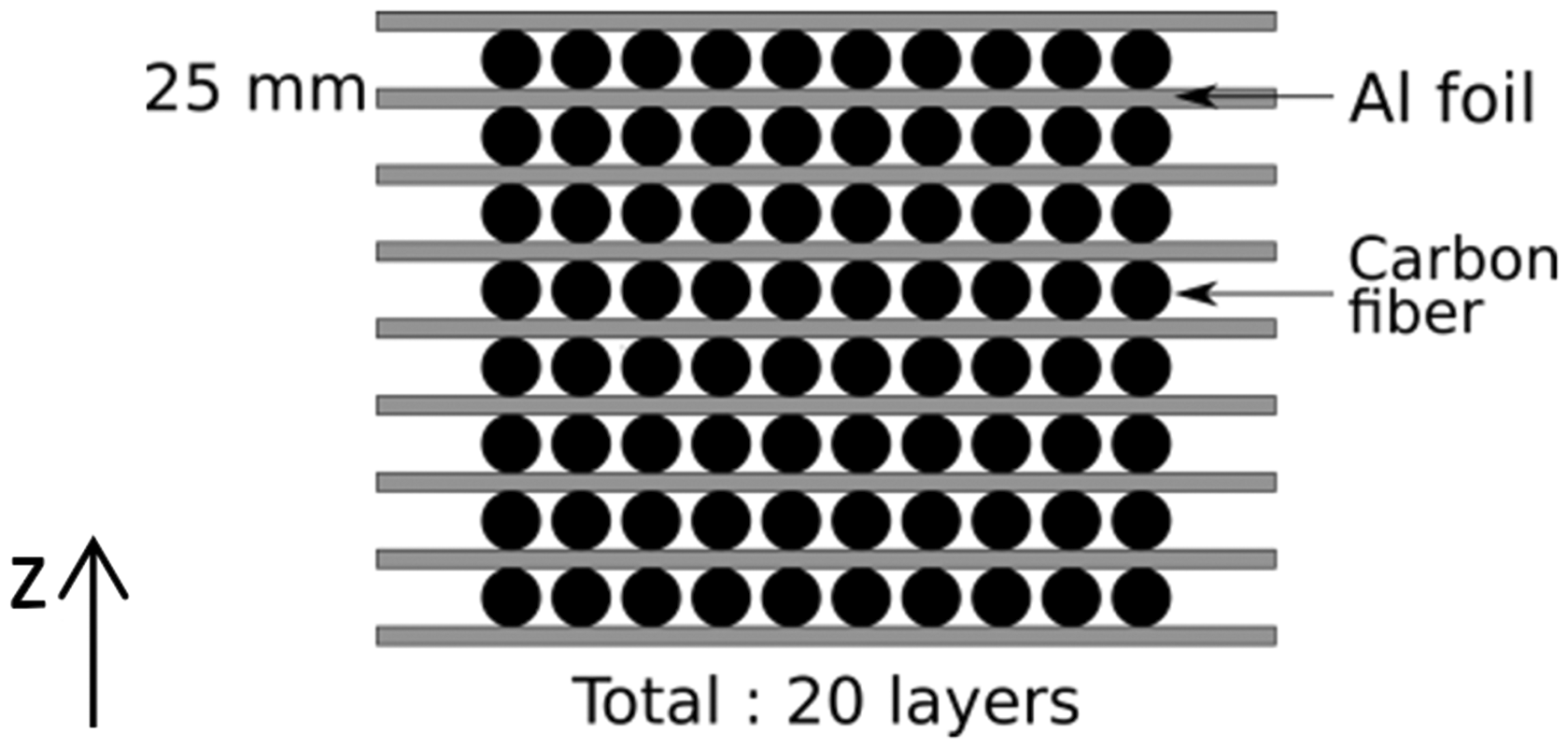
Quality assessment of fibre/matrix coupling
The study of the interfaces gives an idea of the quality of the MMC obtained. It is important to examine them closely, carrying out physico-chemical analyses, mechanical tests and observations of the fibres (orientation and degradation). For instance, aluminium carbides may include notch effects that decrease the ultimate composite strength. There are two types of interface to study: the interface between the aluminium sheets, when it is discernible, and the interface between the carbon fibres and the metal matrix.
Mechanical coupling
In order to check if the bonding between aluminium and carbon fibres shows cohesion, tensile tests were carried out on halter-shaped composite samples with 5 × 0.5 cm2 cross section. With a fibre volume fraction of 40%, the modulus predicted by the rule of mixture is 355 GPa.
The stress-strain curve first shows an elastic behaviour up to a strain close to 0.02%. Then the curve bends slightly before rupture, which occurs at a strain rate equal to three times the strain at the yielding point (Figure 13). This change in slope appears to have occurred following an effect presumed to be damaging because unloading curves are linear and return to a null strain. Reloads then follow the same path with a slope designated Edamaged. This damage effect is then not due to plasticity but is related to “damageable elasticity”.
Stress-strain curve of composite sample until rupture (blue), discharge curve (red).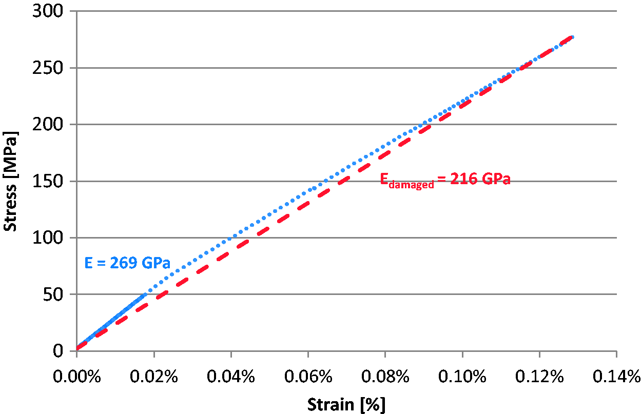
The average measured modulus for the processed composites is 269 GPa, which is lower than expected by the rule of mixture. This result can be attributed to fibre disorientation. Indeed, fibres are placed manually and their disorientation could be measured at between 1 and 14°. Hence, we could evaluate the expected modulus Eθ using the formula related to a disoriented unidirectional (UD) ply.49 This leads to an expected modulus of 302 GPa. Fibre disorientation actually impacts the composite modulus by more than 10%.
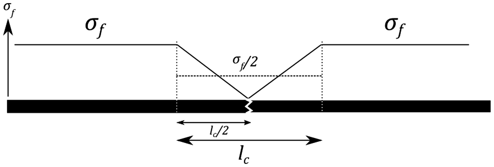
Another phenomenon that has an impact on composite modulus is fibre damage. Carbon fibres may indeed suffer multiple ruptures. Although fibre damage was low, SEM observations showed that it did occur. This suggests that fibre fragmentation already occurs during the manufacturing process. In addition, in a discontinuous fibre-reinforced composite, there is a critical length lc required for the load to be fully transferred to the fibres (Figure 14). Hence, each time a fibre breaks, its length supporting the load is lowered (Figure 15). This fragmentation phenomenon may then occur gradually during the tensile tests, lowering the composite modulus without resulting in any non-elastic behaviour for the material. A coefficient representing this damaging effect was set up, assuming that the load is linearly transferred along the critical length lc.
Representation of the transfer of charge between a filament and the matrix in a composite material. Representation of the distribution of the stress around a filament break.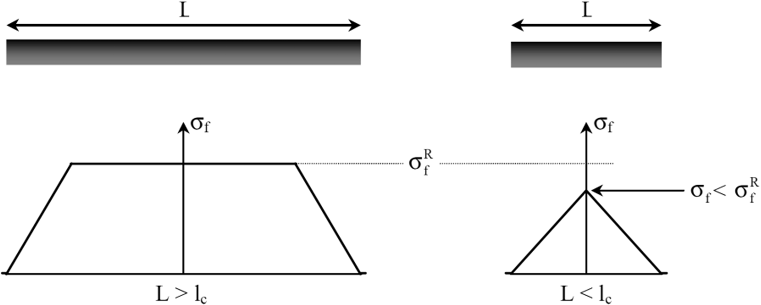


The evolution of this coefficient could then be drawn together with the strain rate (Figure 16). On the tensile test previously shown in Figure 13, η is initially 0.87 until the composite modulus lessens around 0.022%. The rupture occurs for η = 0.66, before maximum damage (η = 0.5). This result could be predicted as the composite rupture took place for 0.13%, whereas the maximum fibre elongation is 0.5%. Aluminium carbides may also be the cause of that rupture.
Young’s modulus and efficiency coefficient evolution during tensile test of a composite sample.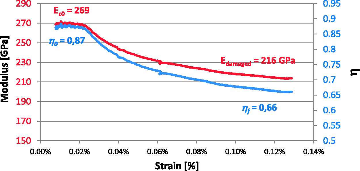
The observation of fractographs has shown very interesting behaviour of the sintered materials. Samples obtained with aluminium foils show only ductile rupture but delamination occurred between each pair of initial foils (Figure 17). When we add carbon fibres, aluminium still appears ductile but the bonding between sheets is more effective as much less delamination occurs (Figure 18(a)). Aluminium is ductile deformed between filaments even though some left their cavities following the rupture (Figure 18(b)).
Fracture surface of aluminium sample (sample produced at 550℃ with pressure of 50 MPa applied on the specimen from 500℃). Fracture surface of composite sample (sample produced at 550℃ with pressure of 50 MPa applied on the specimen from 500℃).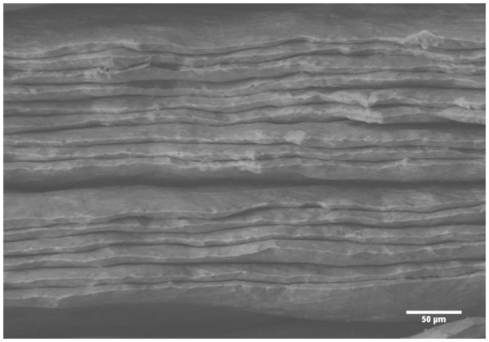
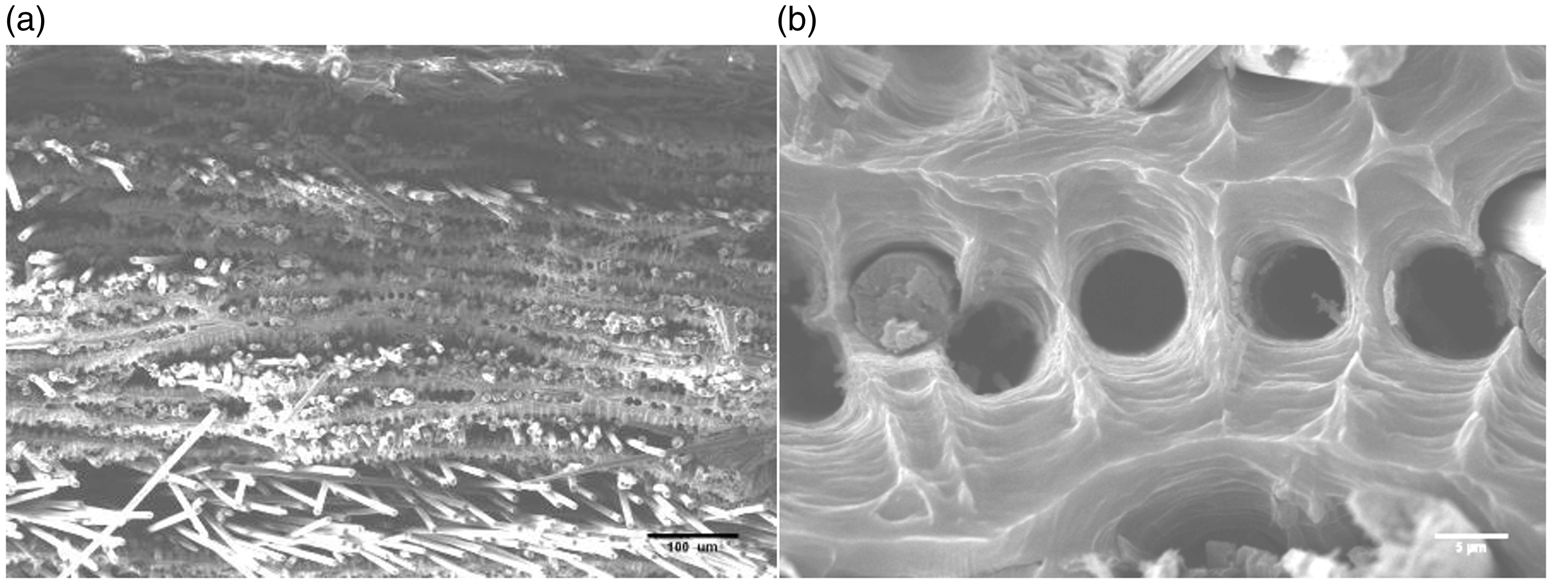
Hence, the addition of carbon fibres to aluminium through the foil–fibre–foil technique resulted in high specific stiffness but also improvements in the bonding between aluminium sheets. This mechanical analysis provides information about the quality of the coupling between aluminium and fibres. Physico-chemical analysis of bonding may explain such behaviour and give additional information on the process and the presence of carbides.
Analysis of interfaces
Aluminium sheet bonding
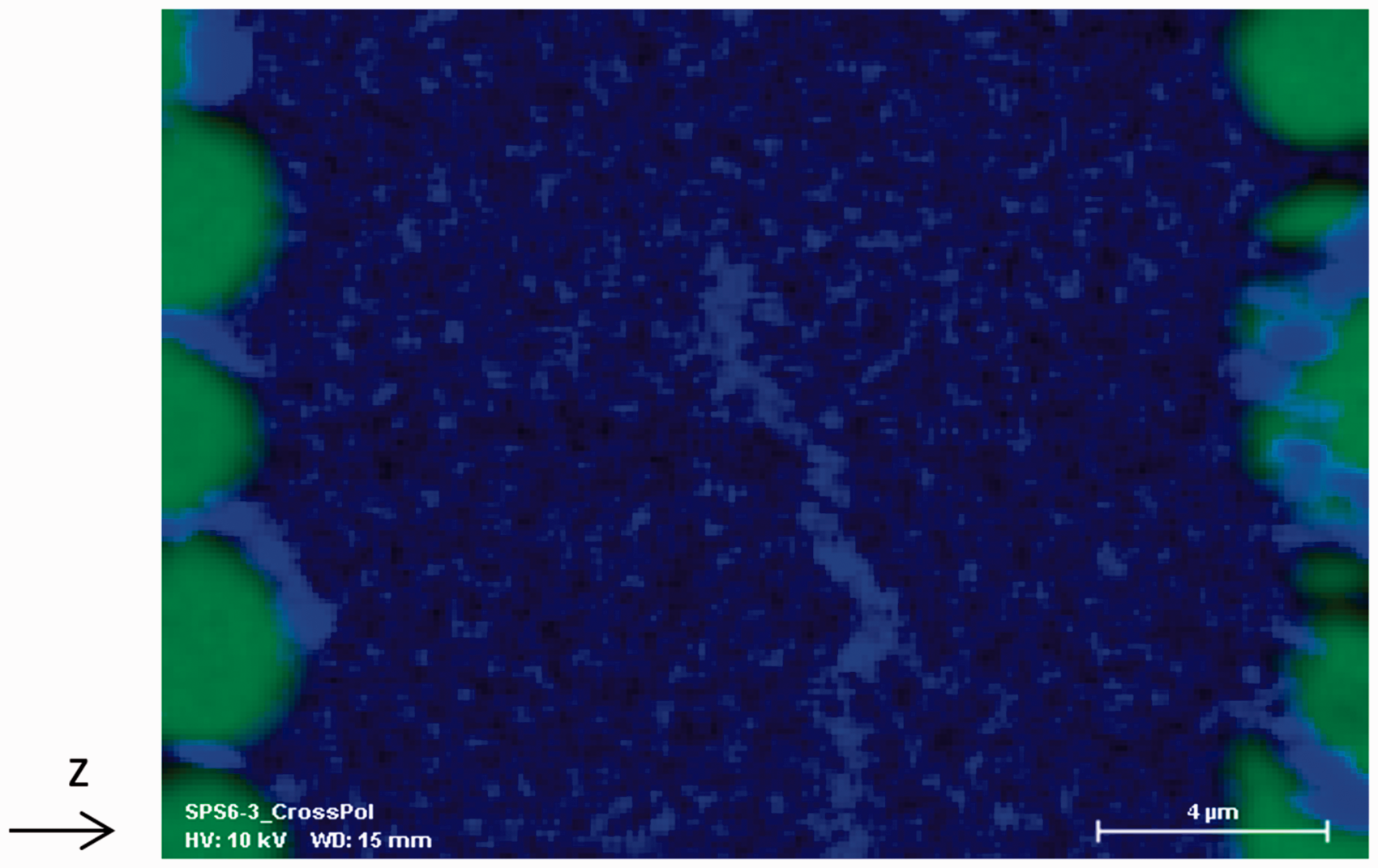
Interfaces between sheets remain discernible when there is contact between two sheets with no carbon fibre (Figure 19). They are clearly discernible under the electron microscope and are free of apparent cohesion defects. EDS analysis reveals peaks in the presence of oxygen within the samples. These oxygen peaks coincide with the boundaries of the layers of aluminium sheets, but also with the ferrous compounds present in the sample. An analysis shows that this alumina layer may be discontinuous along the junctions between sheets (Figure 20).
(a) Cross section of a sample without fibres showing interfaces between sheets (SEM – BSE); (b) Associated EDS line analysis of Al and O along the arrow (non-quantitative data – normalized with Al signal – 10 kV). EDS: electron dispersion spectroscopy; SEM: scanning electronic microscope; BSE: Back Scattering Electron. EDS mapping of oxygen (blue) and carbon (green) in a cross section exhibiting oxide break along sheet junction (10 kV). EDS: electron dispersion spectroscopy.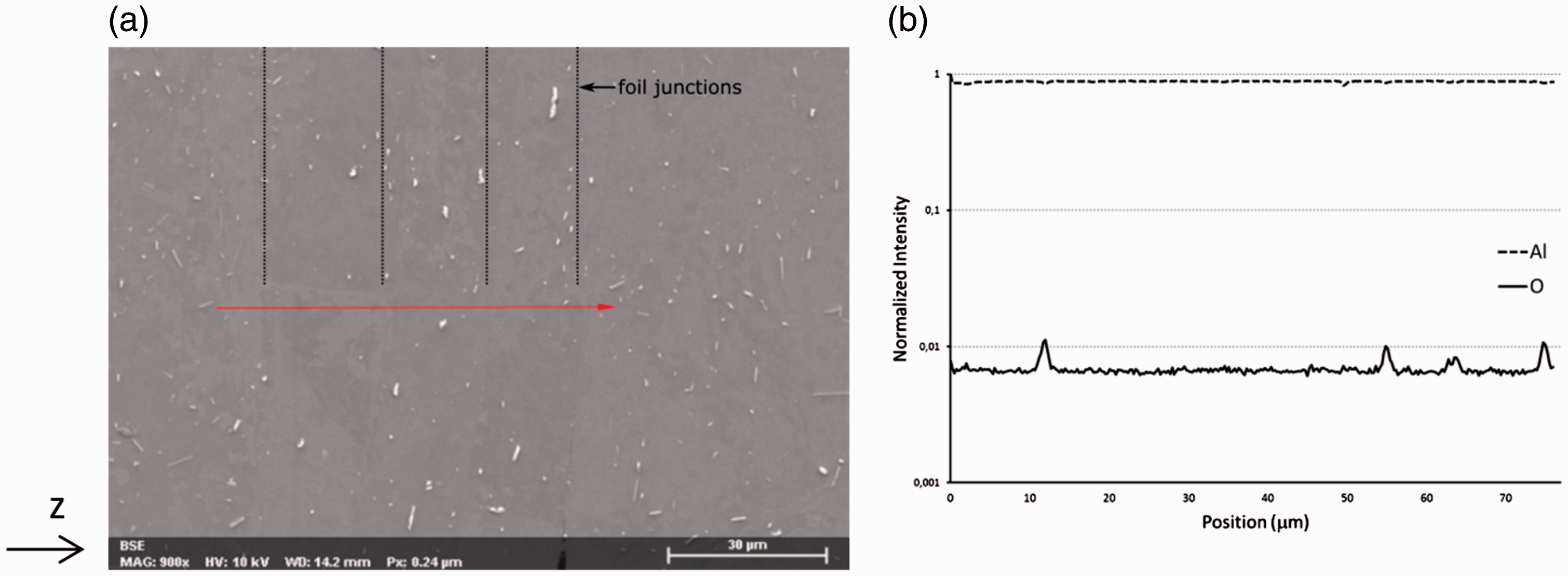
Analysis of fibre–matrix interfaces
One of the reasons for choosing the solid form was specifically to avoid the formation of aluminium carbides. Observations using the SEM at lower acceleration tension (5 or 10 kV) to show cross sections of composite samples reveal compounds entirely surrounding the filaments (Figure 21). Although the matrix shows great penetration between filaments, even in spaces tighter than a few 100 nm, a few spots seem to be still free of aluminium and a lack of bonding between fibre and matrix remains discernible.
Compounds surrounding filaments and partial debonding between filaments and matrix (SE). SE: Secondary Electron.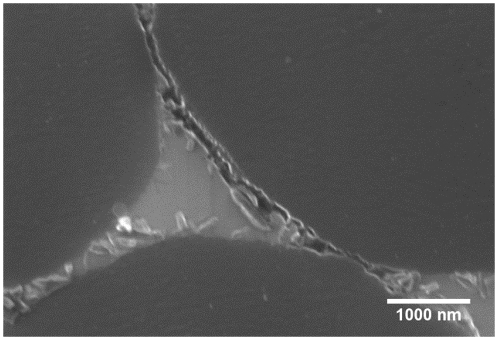
An EDS mapping of Al, C and O was performed; Fe was not detected within the area (Figure 22). This shows that carbon does not overfill the filament section and aluminium is not detected within the filaments. Meanwhile, the compounds surrounding the carbon clearly contain oxygen and aluminium but no carbon, leading to the conclusion that it is made of alumina. The origin of such alumina compounds is assumed to be the result of the rupture of the original surface alumina layer of foils used in manufacture. Because of the loss of resolution due to the nature of the analysis, carbon fibres seem to be bonded. Still, the detection of oxygen within these gaps and higher magnification captions (Figure 21) show that fibres may indeed be down to a few nanometres and close together or even in contact with each other but that they are not bonded. The presence of aluminium carbides was not shown within this scale of analysis.
(a) SEM – BSE picture and associated EDS mapping of (b) carbon, (c) aluminium and (d) oxygen on a cross section of composite sample (5 kV); red square represents an area where thin blade was processed for TEM analyses. EDS: electron dispersion spectroscopy; SEM: scanning electronic microscope; TEM: transmission electron microscopy.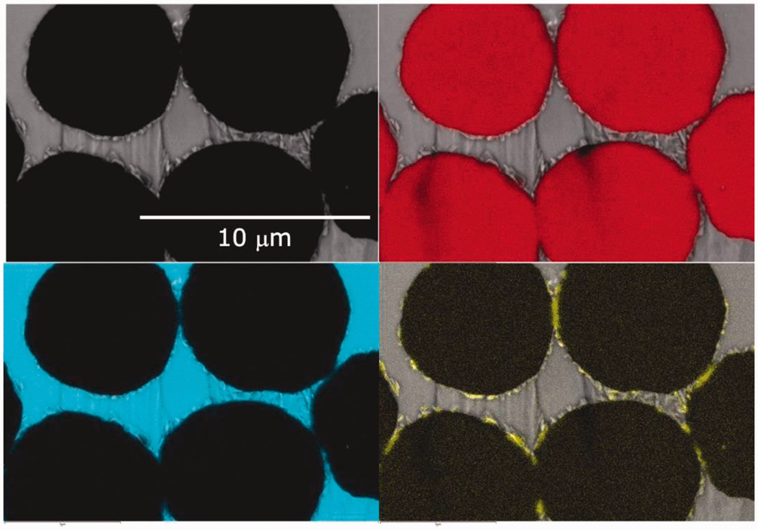
TEM analyses were carried out on a thin blade to study the foil–fibre interfaces in greater detail. The blade was processed using focused ion beam between two filaments closer than 1 µm. Such tight areas – where aluminium infiltrated – are the most crucial for interfaces since they are the most suitable for aluminium carbide (Al4C3) to create, as will be discussed later. These analyses have shown that aluminium carbide was indeed created within the process. Lath-like crystals under 0.5 µm in length and a few tenths of a nanometre wide were sometimes found stuck along the carbon fibres (Figure 23). EDS analysis of these crystals confirmed that they are made of aluminium carbides and their morphology matches the literature descriptions. However, the number and size of the observed carbides are lower than the amounts created through liquid routes,
50
confirming the short duration of local melting.
(a) STEM observation of aluminium penetrated between two carbon filaments showing the presence of lath-like crystals along filaments; (b) magnification on a carbide crystal. STEM: Scanning Transmission Electron Microscopy.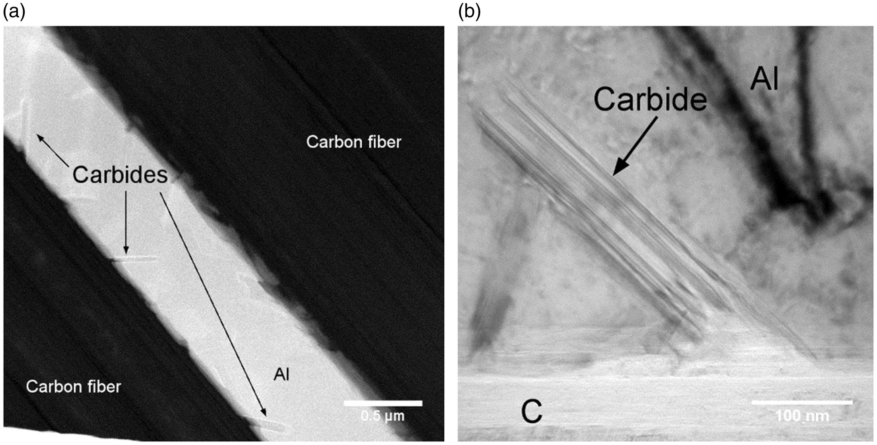
In order to complete the study of the quality assessment of fibre/aluminium coupling, we have characterized the diffusivity of the composite material.
Thermal coupling
To measure the thermal diffusivity of the composite material in the direction of the fibres, we used a technique developed specifically for thin plates. 51 It consists in sending continuous power onto a sample surface using a bonded heated resistance. The difference in temperature change at two measurement points enabled us to estimate thermal diffusivity. The first results obtained show that the thermal diffusivity of the composite material is 1.7 times higher than that of aluminium alone, thus confirming the previous results.
Discussion
Processing aluminium foils and carbon fibres by SPS resulted in samples with perfect penetration of the matrix into reinforcements. To achieve such a result, the dwell temperature was set to 550℃ for 10 min under vacuum. A mechanical pressure of 50 MPa was applied between 500 and 550℃ during the last two minutes of the heating step after it was found that filaments suffered heavy damage and the matrix did not penetrate the fibres.
In cases where the aluminium is molten, such as those at 575℃, the metal leaks out along the pistons as the assembly is not watertight. In the tests carried out at 550℃, resulting in full penetration of the metal, this phenomenon was not observed. It is therefore acknowledged that full melting of the aluminium is excluded.
In addition, it was shown that applying pressure when the metal is hot rather than cold results in good penetration of aluminium into tight gaps between carbon filaments. Hence, aluminium creep may be the first mechanism involved. When hot, the metal is in a viscoplastic state and tends to flow between the filaments with the action of the applied pressure. This phenomenon requires a certain amount of time to reach full penetration, which would explain the insufficient penetration of the matrix observed when the hold time was under 10 min (Figure 9). Still, the presence of aluminium carbides suggests that the liquid state was reached, in accordance with the literature.19,50 Localized melting over a short period must therefore be considered.
Other studies have estimated that in the case of powders sintered by SPS, the temperature can therefore be very much higher at the contact points between two aluminium particles than in the bulk of the material because of the convergence of the current in necking representing a tight section.52,53 Within our study of foil–fibre–foil technique, similar hot spots may be formed at the contact between foils and fibres. These can then result in localized melting of the aluminium which then infiltrates between the carbon filaments into tight areas under the action of pressure. Carbides may form during this step. However, the further the infiltration progresses, the wider the interfaces between the sheets and carbon become. Hot spots resorb as the current becomes more uniform.
Consequently, it seems that a gradient of several tens of degrees/µm may occur during the process. This is part of the numerous debates about SPS that are still ongoing and for which many studies are willing to determine the real temperature reached by the sample, whether it is an electrical conductor or not.31,44,54–57
Conclusion
We conclude that continuous carbon fibre-reinforced aluminium could be manufactured by SPS using the foil–fibre–foil technique. The sintering temperature was selected to ensure good infiltration of the fibres. Applying pressure (50 MPa) when hot and with a holding time above 10 min, we observed good infiltration into the fibres by the aluminium with little filament damage. Apart from a few occasional defects, little lack of bonding between fibre and matrix could be seen in the samples. Local melting of aluminium has been identified as playing a role in achieving full infiltration as aluminium carbides were found. However, the amounts observed are moderate compared to liquid processing routes and hopefully could be controlled in further studies along with a better understanding of SPS technique. In addition, the foil–fibre–foil technique led to a high specific stiffness. The overall results show that AMCs could be a solution to improving the properties of aluminium, such as thermal conductivity.
Footnotes
Thanks to Alain Largeteau and U-Chan Chung Seu of ICMCB (University of Bordeaux – France) for providing the SPS facilities and to the Raimond Castaing Characterization Center for TEM analyses (University of Toulouse – France).
Declaration of Conflicting Interests
The author(s) declared no potential conflicts of interest with respect to the research, authorship, and/or publication of this article.
Funding
The author(s) disclosed receipt of the following financial support for the research, authorship, and/or publication of this article: The authors gratefully acknowledge the financial support from BPI France.