
Abstract
High-performance textiles are used for reinforcing concrete structural parts. This paper presents a technique for producing coated weft-inserted warp-knitted fabrics for concrete applications. Three types of reinforced fabrics differing in coating type and composed of alkali-resistant-glass rovings resulting in a cement composite matrix were produced. The investigated coatings include potassium silicate, carboxylated styrene butadiene rubber and epoxide. The mechanical properties of the developed fabrics and cement composites were determined according to the coating type. Thereafter, the mechanical performance of the warp-knitted reinforced fabrics was investigated using tensile tests. Finally, the properties of the composites were examined according to the coating type using a four-point bending test. The results of the characterization of the coated weft-inserted warp-knitted reinforced fabrics and cement composites based on them are presented and discussed. It is shown that the coating material has high influence on the composite properties. Samples with potassium silicate showed highest strength at the limit of proportionality, while samples with epoxide showed the highest flexural strength.
Keywords
Introduction
Fibrous materials have found widespread application in the reinforcement of structural composites in recent years. 1 In the past, focus has been laid on textile fabrics made from continuous yarns and rovings. Unlike discrete particle and short-fibre fillers, textile reinforcement allows for the realization of high-performance yarns or rovings. Such textile reinforcement is widely used for reinforcing composites using a polymer matrix. Moreover, now high-strength textile finds new applications such as reinforcement of concrete composites, representing a combination of textile-reinforcing fabrics and the concrete matrix. This combination has led to the formation of a fundamentally new class of structural materials – textile-reinforced concrete (TRC).1,2 TRC finds diverse applications, ranging from a variety of architectural elements to load carrying reinforced concrete-based structural members. The main advantage of TRC is the minimal concrete covering required for textile fabric bonding. 3 Its advantages also include minimized need for concrete material, good ductile failure behaviour, thin-walled structure of elements and flexible design possibilities, which make it an ideal candidate for various applications such as façade panels,4,5 pedestrian bridges 6 and heating elements. 7 With regard to load behaviour, TRC having no plastic capacity has no distinct failure symptom when the ultimate load is reached, and this limits its use in load-bearing applications. 8 In general, TRC elements exhibit improved load capacity, energy absorption and impulse absorption. 9
The development of new types of textile reinforcement with the use of new types of high-strength yarns led to improved properties of load carrying structural building elements.10,11 Various yarn structures have been employed for composite reinforcement. These yarns include not only rovings but also high-strength yarn structures composed of alkali-resistant (AR) and carbon materials. In recent years, the development of appropriate yarn structures has been investigated intensively10,12–15 to improve the performance of reinforced fabrics and thus the mechanical performance of structural elements made of TRC. It has been observed in some studies that existing design methods for concrete cannot be applied to new types of TRC. Therefore, some new approaches for designing cement composites reinforced with textile have been developed.16–18 It has been shown that the mechanical properties and bond strength of reinforced concrete are mainly determined by the properties of reinforced fabrics. The reinforcement efficiency (RE) is determined by fibre type, fibre diameter, fibre volume fraction and fibre orientation. Further, it has been noted that TRC exhibits different bond behaviour from that of steel-reinforced concrete owing to the inhomogeneous cross-section of rovings. 1 For the manufacturing of TRC, yarns or rovings are usually processed for warp-knitted 2D12–14 and 3D 15 textile reinforcement structures. These textile reinforcements are embedded into fine-grained concrete with particle size <2 mm to absorb the applied tensile forces. The parameters of the structure of the textile fabric, as well as the properties of its constituent yarns, affect the properties of the resulting concrete matrix.1,10,12 Variation of these parameters can improve the adhesion to the concrete matrix and hence enhance the reinforcing effect.12,13 For uncoated textiles, only the outer filaments are anchored in the cement matrix. The anchorage of the outer filaments in the cementious paste is good. The inner filaments are not reached by the cement matrix during the production of TRC components. Therefore, there is no anchorage between the cement matrix and the core filaments. The distribution of applied loads to the core filaments is only possible via low friction between the filaments. 1
The dimensional stability and strength efficiency may be improved by applying polymer coating to the reinforcing fabrics.1,4,8,19–31 Due to the high viscosity behaviour of the polymer, the impregnated textile is less drapable and thus stiffer to handle and cast using conventional processes. With thermoset polymers, such as epoxy resin, it is possible to produce stiff reinforcing skeletal structures, similar to steel reinforcement. The second effect of the coating provides an improved stress distribution within the yarn. The coating locks the filaments through adhesion and thereby improves the inner bond and load transmission within the yarn. An important aspect of the use of polymer coatings is the adhesion and force transmission to the concrete matrix. Pull-out tests with various epoxy resin systems have been carried out by Hegger et al. 4 It was found that the highest pull-out force is achieved by the application of a coating of vinyl ester urethane resin. An impregnation of the AR-glass fibres with different epoxy resins increases the pull-out force significantly. 22 The degradation of glass fibres in alkaline environments has been known since mid-1970s. Different approaches can be found for making glass fibres more resistant to alkaline environment. The application of acrylic polymer dispersion to the glass roving as well as to the concrete matrix has been investigated using pull-out tests, four-point bending tests and micro-strength tests. An embrittlement of the bond has been observed in the analysis of the four-point bending and pull-out tests. Simultaneously an increase in micro-strength of the interface was also observed. 23 An impregnation of AR glass fibres with styrene butadiene coating material was carried out by applying coatings of two different polymer contents (2.4 and 7 wt%). After an exposition of the fibre material to a defined alkaline environment coated AR-glass rovings featured a higher durability and better mechanical performance. 24 In recent publications, styrene butadiene coating material is combined with multi-walled carbon nanotubes and nanoclay. The nano-modification improves the environmental corrosion resistance of AR-glass fibres. 25 A combination of a soluble polymer and fine-grained cement was applied to AR-glass rovings. The unhydrated cement in-between the filaments reacts completely when embedded in concrete samples. The cement between the filaments forms a continuous bond between roving and concrete matrix after crystallization. Pull-out tests showed an enhanced strength of the bond between roving and the matrix. 26 In another approach, the application of inorganic coatings onto the rovings was investigated. E-glass fibres were coated with a CaO–BaO–SiO2–TiO2 and showed a better bond between fibre and concrete as well as a better durability. 27 The application of a SiO2–ZrO2 coat via sol–gel coating results in an increased durability of the E-glass rovings. 28
In general, coating the textiles makes them more stable, improves mechanical properties, bonding and increases the rigidity compared to non-coated fabric cement composites.29–31 The mechanism of transferring stresses from the fibres to matrix is improved by better bonding of inner and outer filaments in the roving. Epoxy coating enhanced the ultimate load bearing capacity by more than 70% compared with uncoated textiles. 29 Dvorkin et al. studied the mechanical performance and fluid ingress of fabric cement-based components made of epoxy-coated and non-coated multifilament carbon fabrics. It was shown that coated system improves mechanical behaviour, bonding and reduces crack width and develops dense branched network cracks. 30 In Donnini et al., 31 three different levels of epoxy impregnated carbon fabric-based cement composites were investigated using tensile, shear and pull-out tests. It was found that the mechanical capacity of all samples increases for both tensile and shear tests. Along with this, epoxy resin adversely effects the ease of applications. The transition point between the uncracked and cracked phase showed a capacity drop due to the insufficient reinforcement required to support the load transfer after the formation of the first crack.
Materials and methods
Materials
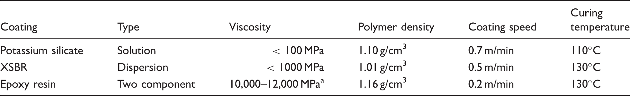
As a reinforcing material for concrete composites, AR-glass (Cem-FIL) yarns are used. The linear density of the yarn is 1200 tex. A continuous filament polyester yarn, used primarily as the knitting yarn, has a linear density of 16.7 tex.
Development and production of coated warp-knitted fabrics
For the production of coated fabrics, weft-inserted warp-knitted fabrics are selected as the baseline, consisting of biaxial structures of glass rovings laid in two directions and connected by a knitting yarn. Such a reinforced fabric contains straight yarns, in contrast to woven fabrics, and the knitting yarn provides reliable anchorage of the reinforcing rovings, which results in a high dimensional stability of the fabric geometry. The fabric samples are produced on a warp-knitting machine (MALIMO/c/P2-2S, Karl Mayer Textilmaschinenfabrik GmbH) at the Institute of Textile Technology of the RWTH Aachen University. AR-glass rovings were used as the warp and weft inlay yarns. The samples contain two pairs of rovings per inch of fabric width as shown in Figure 1. The parameters of the reinforced fabric samples are listed in Table 1.
Structures of warp-knitted fabrics. Characteristics of the warp-knitted fabrics. CTF-N: non-coated fabric; CTF-S: coated fabric with the silicate; CTF-X: coated fabric with XSBR; CTF-E: epoxy-coated fabric.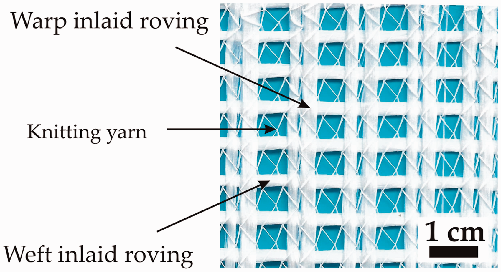
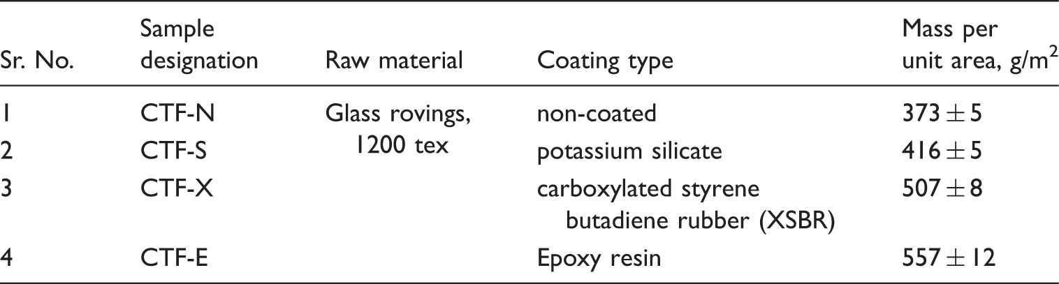
All fabric samples were coated continually on a Jakob Weiss PCS 30 coating machine. All textiles were coated roll to roll. The polymers were added in a Foulard, calibrated by squeezing rollers and cured in an oven. The coating machine is shown in Figure 2. While applying the epoxy resin, the Foulard and the squeezing rollers were heated to a temperature of 80℃. The coating speed was adjusted to achieve an optimum impregnation of the fabric. An increase in viscosity of the coating material led to a reduction in coating speed. The time required for complete penetration of the coating material into the fabric is directly proportional to the viscosity of the coating material. The process parameters and properties of the applied coating materials are given in Table 2. The process parameters of the coating process were selected according to the manufacturer’s recommendations in order to provide optimal results.
Coating process. Characteristics of the coating process. at room temperature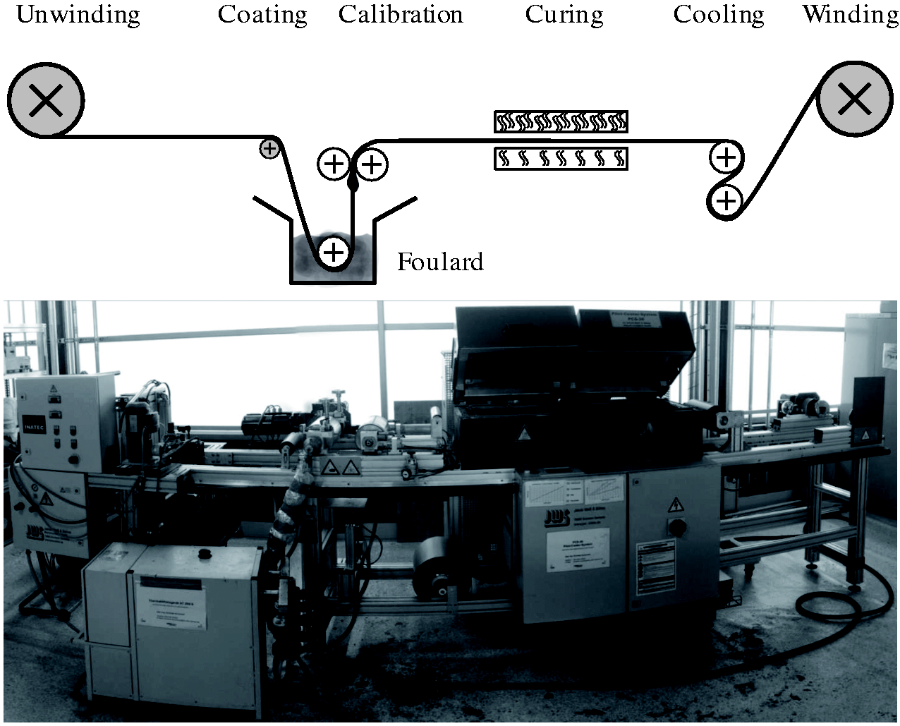
The amount of coating material applied on the fabric is measured by weight and is given in Table 1. Due to the different viscosity of the materials, the coating speed is also different. Potassium silicate is applied with the highest speed of 0.7 m/min, carboxylated styrene butadiene rubber (XSBR) is applied with 0.5 m/min and epoxy resin with 0.2 m/min. Potassium silicate and XSBR are single-component systems, whereas epoxy resin is a two-component system. This means that epoxy resin is mixed with component A and component B before coating and is usable only for a limited time, typically several hours. Single-component systems are not constrained by cure time. All systems chosen for these experimental trials were solvent free.
Fabrication of cement composite samples
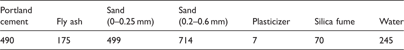
Fine-grained concrete was used to manufacture the cement composite samples. The mix proportion of fine grain concrete is given in Table 3.
32
Samples of TRC are made using the mould shown in Figure 3(a) to (b). The mould, which is made of Teflon, is a prefabricated construction consisting of three frames. This structure allows for the fixing of two layers of fabrics at a certain distance from each other. The length of the samples was 270 mm, width 180 mm and thickness 30 mm. Two samples of the reinforced fabrics are placed in tension and compression areas at a distance of 7.5 mm from each edge, as shown in Figure 3(c). Thereafter, the resulting plate is cut into three separate specimens with width of 60 mm, as shown in Figure 3(d). The fibre volume fraction in the manufactured samples is approximately 0.7%. The test samples are kept for 28 days at 23℃ and 95% relative humidity before testing.
Mould for casting the concrete samples: (a) scheme of the mold, (b) fabrication of the concrete specimen, (c) side view of the reinforced concrete, (d) cutting of the reinforced concrete sample. The constituents of fine grained concrete (kg/m3).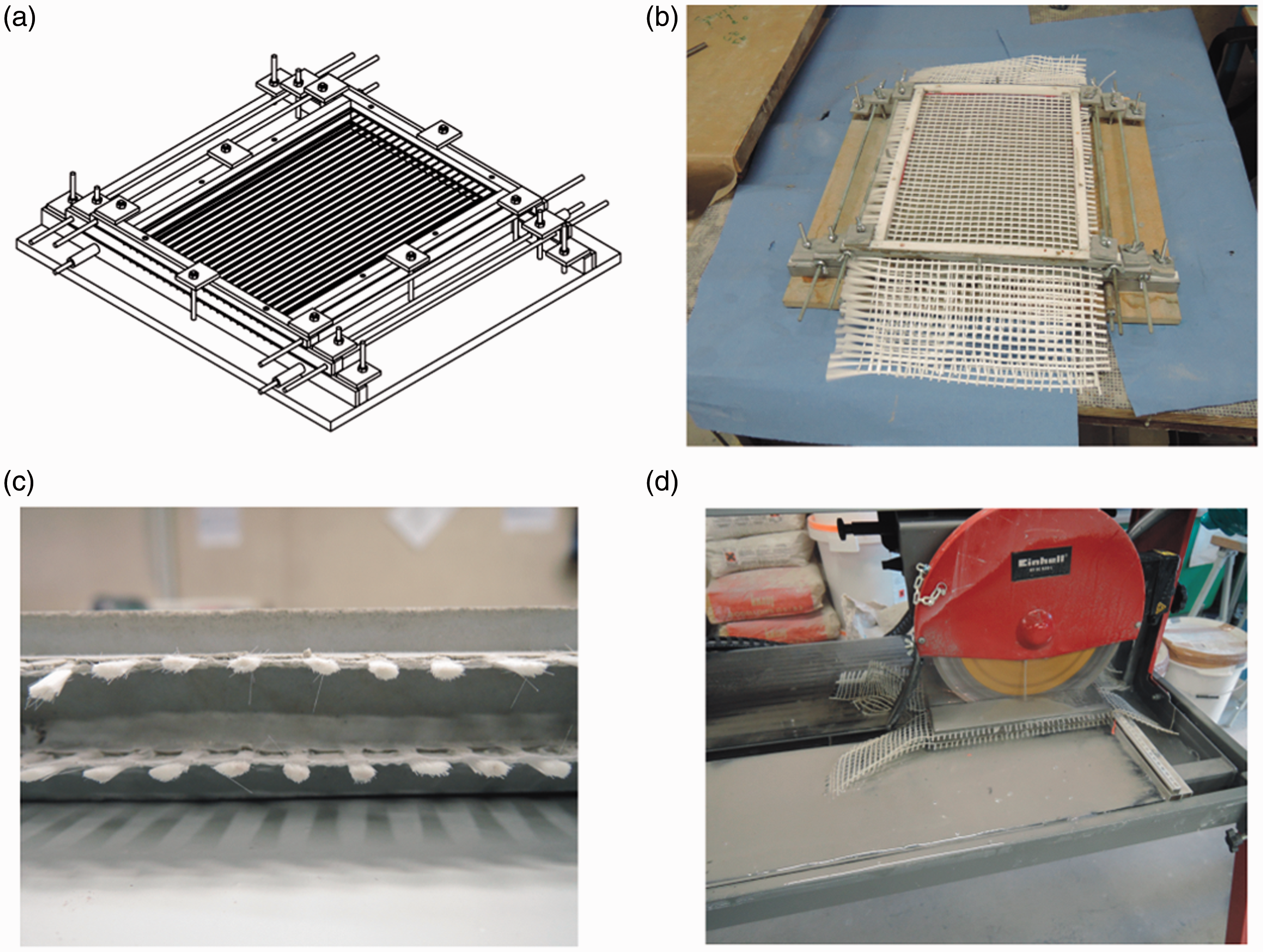
Tensile testing of the coated fabrics
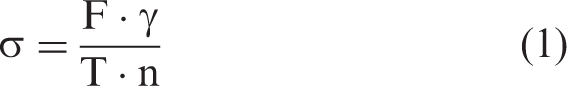
Samples of coated fabrics for tensile testing are prepared in the form of strips with a width of 50 mm and a length of 200 mm. The clamping length is 100 mm. To prevent damage to the free ends of the fabrics in the clamps, they are impregnated with epoxy resin. The test is carried out at a speed of 10 mm/min. Based on the results of tensile test, the two most important characteristics namely, tensile strength (TS) and Young’s modulus were determined. Tensile stress was determined as follow
Four-point bending test of concrete
Samples of cement composites were tested in a four-point bending test according to DIN EN ISO 12390-5. The specimens with dimensions of 30 × 60 × 180 mm were cut. The flexural tests were carried out in a Zwick Z100 testing machine at a span of 60 mm. The specimens were constantly loaded at a rate of 1 mm/min. No fewer than five concrete specimens were tested.
Based on the results of the bending test, two most important characteristics including strength at the limit of proportionality (LOP) and maximum flexural strength (MFS) were determined. The strength at the LOP shows the highest stress in the linear region of the stress–strain curve and MFS determines the highest stress that the specimen withstands during the test. It should be noted that deflection of the samples was determined from crosshead displacement.
Analysis of coated fabric cross-section
The cross-sections of the coated fabric samples are examined by optical microscopy in order to reveal the effect of the coating type on the structure. In order to achieve this, the fabric is impregnated with a transparent epoxy resin. Upon curing, the surface of the samples is polished. Micrographs of cross-sections are obtained with the help of a digital camera of an optical microscope (Leica type DM 4000 M).
Statistical analysis
Statistical analyses were conducted using one-way analysis of variances (ANOVA) for significant differences at 0.05 significance level. One-way ANOVA was performed to evaluate the effects of the coating type on the TS of coated fabrics and flexural properties of cement composites. Tukey honest significant difference (HSD) post hoc test was performed to examine the significance of the differences between the average values of TS of coated fabrics, strength of the LOP and MFS of cement composites.
Results and discussion
Effects of coating type on the mechanical properties of fabrics
Based on the studies conducted towards determining and analysing the mechanical behaviour of coated fabrics, a significant influence resulting from the coating type is observed. The stress–strain diagrams of the coated fabric samples are shown in Figure 4. The main tensile characteristics of the fabric samples including TS and Young’s modulus are determined. The obtained data are presented in Figure 5, where the column bars indicate the average TS with 95% confidence interval. It should be noted that in determining the TS and Young’s modulus of the fabric samples, the values were calculated relative to the cross-sectional area of the original non-impregnated roving.
Stress–strain curves of fabric samples using different coatings. Tensile properties of coated fabric samples, including 95% confidence interval.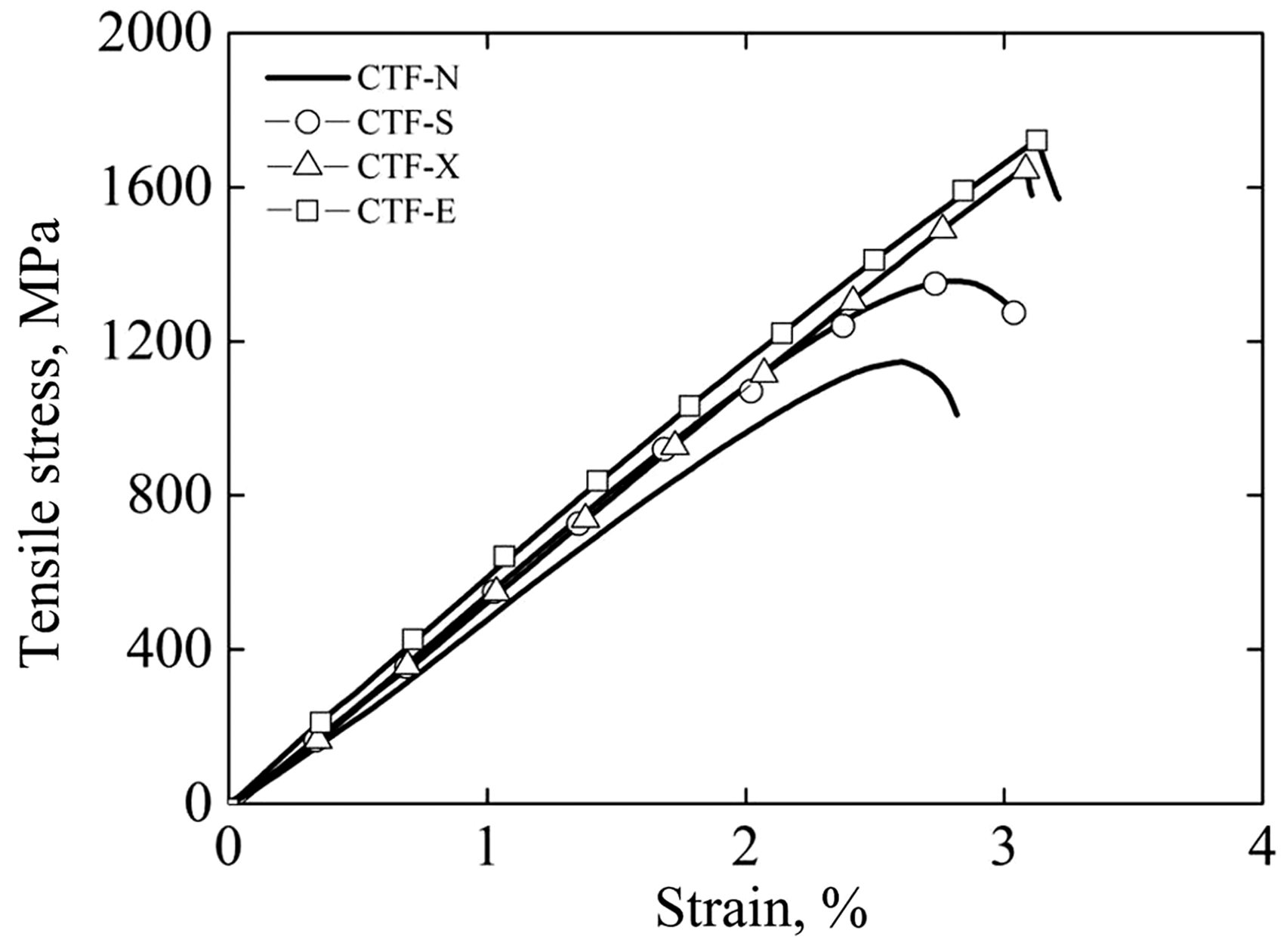
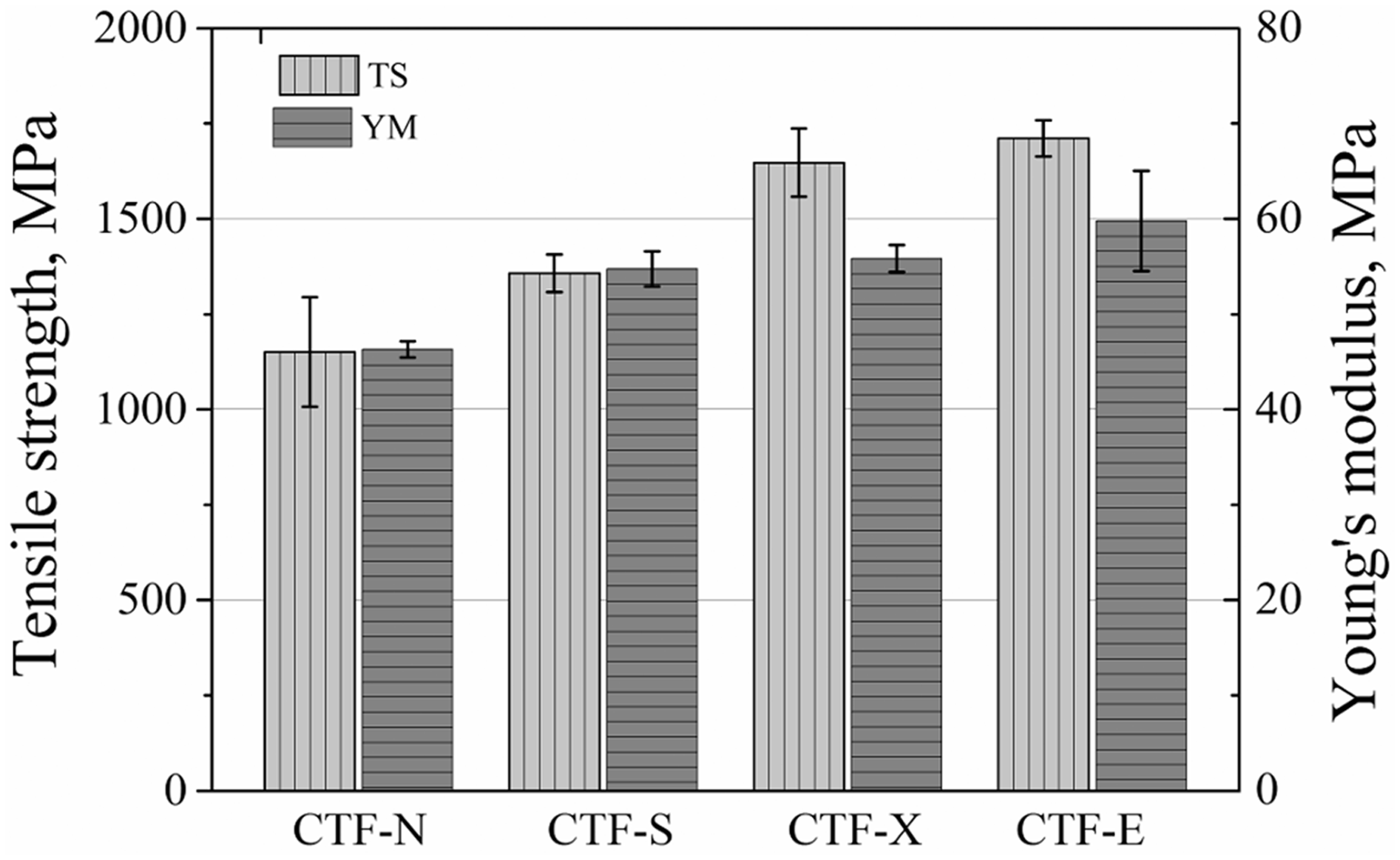
As can be seen from the graph, TS of the coated fabrics increases with the application of coating and is a function of the mass per unit area of the fabric. The TS of the reference non-coated sample (CTF-N) is 1150 MPa, while the TS of the epoxy-coated fabric (CTF-E) is 1711 MPa, i.e. it increases by a factor of ∼1.5. In the case of sample (coated fabrics with the silicate (CTF-S)), the TS increased by 18% in comparison to that of the reference sample. The sample of the fabric with XSBR (CTF-X) showed higher TSs (value of CTF-X was higher by 43.3%, in comparison to the values shown by CTF-N). It can be explained by the fact that increase of strength is based on an even stress distribution among the filaments. Due to the coating, local stress peaks caused by imperfections such as broken filaments or undulations are transferred to the neighbouring filaments.
The effect of the coating type on the Young’s modulus is not as significant as the TS. However, with the use of epoxy coating (CTF-E), the value of the Young’s modulus increased by almost 30%. In comparison to the non-coated fabrics, the Young’s modulus for the epoxy-coated fabrics increased because the filaments in the rovings are not perfectly oriented in the load direction. Small variations in the orientation angle lead to a state where some filaments are already load bearing while others are free to translate under load. This leads to a lower Young’s modulus. When epoxy coated, the slip of the filaments is decreased highly and thus the state of moving filaments is decreased. This leads to an increase in Young’s modulus. The Young’s modulus for the coated fabrics with the silicate (CTF-S) and XSBR (CTF-X) are about 18.3 and 20.6%, respectively, higher as compared to the corresponding non-coated fabric sample.
The observed characteristics of the tensile curves are also different. With increased stiffness of coated fabrics (CTF-X and CTF-E), a sharp increase in load carrying capability is observed. However, the failure characteristics observed in this case mimic those of a brittle material transitioning to plastic deformation while providing little or no preceding failure warning. In fabric samples, CTF-N and CTF-S failure occurred earlier than that in fabric samples CTF-X and CTF-E. The observed increase in the strength and elongation of coated fabric samples is mainly due to a significant increase in the strength properties of individual filaments and the resulting composite matrix after impregnation.
Cross-section observations
The tensile behaviour of investigated samples showed that the coating increases strength and stiffness of the AR glass rovings. Due to inner bonding, the stress is distributed more evenly between the filaments and local stress peaks were prevented. With increase of the coating volume fraction, elongation and strength of fabric samples increased. Depending on the type of coating, different bonding effects between the filaments were noted. The schematic design and micrographs of the rovings for the different coating materials are shown in Figure 6. The epoxide fabric (CTF-E) was completely impregnated by the epoxy resin. The XSBR dispersion did not impregnate the core of the roving. Dispersion is applied with high water content. The water evaporates during the curing process. The volume needed for penetration during coating is much higher for dispersions. Within the inner part of the roving, the filaments are more compact and have less space for the coating. In addition, air voids result from the evaporated water. The void in the roving was filled with embedding resin during preparation of the micrographs. For the potassium silicate coating the appearance of the coating, on and in the fabric was distributed randomly with very little volume fraction. There were certain areas in the micrograph that presented a flake-like appearance. Potassium silicate is applied in dispersion with high water content. During the curing process, water evaporates. During evaporation, the water film splits into smaller fractions due to shrinkage. The remaining solid agglomerations look like small flakes with small gaps in between each other.
Appearance of the coated roving and micrographs of the coated textiles.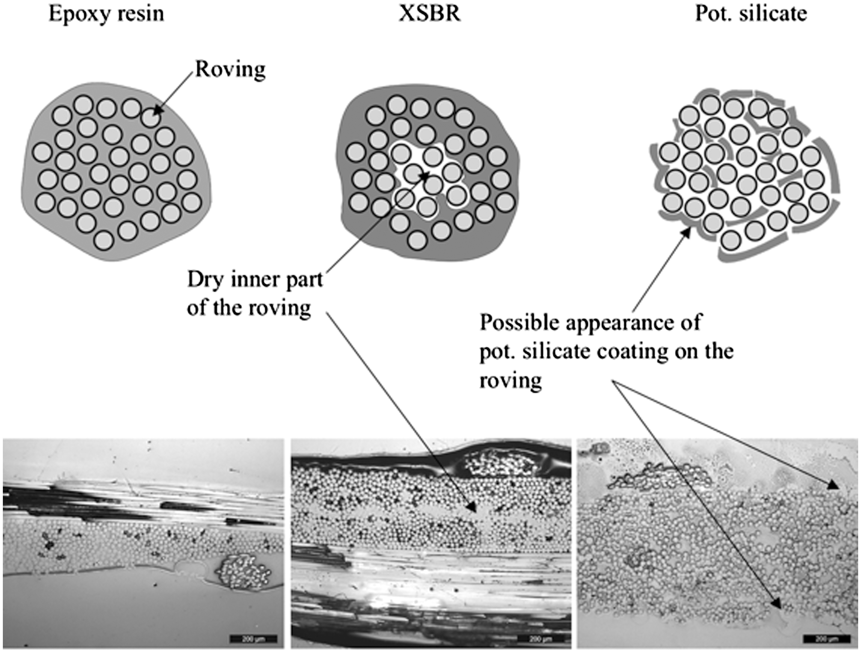
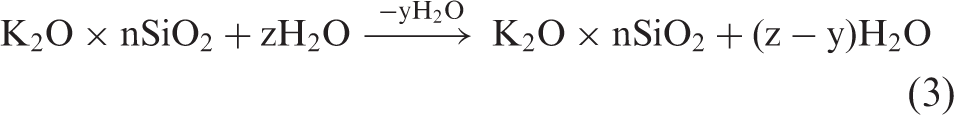
Potassium silicate is supposed to chemically react with concrete. The coating of rovings with potassium silicate enables two effects. First, the penetration depth of the concrete is increased, since the coating reacts with the concrete and does not work as a separation layer like in the case of other polymers. Second, adhesion is increased, because the surface between concrete and fibre is more compatible. The coating of potassium silicate added 43 g/m2 in comparison to the non-coated textile. This exceeds the lowest amount of coating material applied to the fabric. The coating of XSBR added 134 g/m2 and the coating of epoxy resin added 184 g/m2. Because of the high viscosity, epoxy resin forms a thicker layer when coated leading to increased weight. During the curing process, the epoxy resin and the amine-based hardener form a cross-linked network. XSBR is dispersed in particles in water with a content of 40%wt polymer. During the curing process, a closed film of XSBR on the fabric was created by polymerization of rubber. While exposing the coated fabric to heat in the oven, the water evaporates and the ratio of XSBR particles to water increased. When the water evaporated, the polymer particles were packed in a close packing of spherical particles. In the next step, the particles started to undergo deformation and the outer boundaries of the particles were seen to be in contact with one another. In the last step, a closed film was formed since the temperature in the oven was higher than the glass transition temperature of the XSBR particles. In this case, the polymer chains diffuse over the boundaries of the particles. The last coating material, potassium silicate was a solution of potassium silicate in water. The stoichiometry of the glass used for the production of the solution depends on the ratio of potassium carbonate to silicon dioxide.
33

In the solution, the soluble potassium silicate forms a complex system composed of poly silicate ions with a range of a few –O–Si–O– units up to ions with numerous repeat units. The evaporation of water leads to the formation of polysilicic acids.
34
It was found that coatings based on soluble potassium silicate exhibited a moderate strengthening and fixating property as seen from the results of tensile test. In addition, the potassium silicate is an inorganic material, which is preferable when dealing with construction materials in terms of fire resistance and recycling. The epoxy resin consolidates the roving in the most effective manner. It incorporated the entire roving and established a completed inner bond of the filaments of the AR glass rovings. Therefore, epoxy-coated textiles withstand the highest stress in tensile tests. Epoxy coating has the highest strength in this investigation while referring to polymer TS. When the filaments start to break, it has the best properties in transferring the load of broken filaments within the cross-section. Thus, stress peaks are decreased and the bearable maximum stress is the highest. For XSBR coated fabrics, the inner bond was not completely achieved. In the middle of the roving, there was no impregnation with the XSBR copolymer present. This led to a decrease in strength of the inner bond of the roving. The inner bond of the roving that was established by the XSBR coating was less effective compared to the epoxy resin. The XSBR coating leaves uncoated areas in between the filaments. At the state of maximum load, this leads to stress concentrations resulting in rupture and failure as the load levels are further increased. The interaction between the solution of potassium silicate and the AR-glass-based fabric was not completely clear. The increase in mechanical performance in tensile tests of the fabric when compared to the uncoated reference was indicative of the application of some form of coating on or the establishment of an inner bond in the roving. Due to constraints restricting the optical identification of potassium silicate coating in or on the roving of the coated fabric, the exact appearance of the potassium silicate on the roving is uncertain.
Effects of coating type on the flexural properties of cement composites
Figure 7 shows the stress–deflection curves of bending for specimens of reinforced cement composites with different coating types. The results of the bending test of cement composites are taken as a mean curve of five tests for each specimen and are shown as stress–deflection curves in order to evaluate the flexural behaviour of the composite. From the curves, it is clear that the behaviour of the samples varies and depends strongly on the type of coating. These curves characterize the flexural behaviour of the cement composites under flexural loading. In samples with the non-coated (CTF-N) and silicate (CTF-S) fabric reinforcement, a partial destruction occurs, primarily because of the high adhesion of reinforcement and matrix. With further deformation, a miniscule increase in the flexural strength due to resisting fibre glass is observed, reaching a peak with a load level lower than that of the LOP load level. In samples with the XSBR (CTF-X) and epoxy resin (CTF-E) coating, after reaching the first peak, failure occurs stepwise, thereby achieving a high residual load capacity. The initial part of the stress–deflection curve of each sample is characterized by linear properties, with subsequent transition to a part with a slight non-linearity. Following this, there is a first transverse crack corresponding to the maximum peak in the curve. Then, an increase in bending strength due to the resistance of the reinforcing rovings occurs. This process progresses in steps with the formation of several additional peaks. This effect is well pronounced for the CTF-X and CTF-E samples and less for the CTF-N and CTF-S samples. The magnitudes of the flexural strength for different samples corresponding to the LOP are shown in Figure 8(a), and the results of MFS in Figure 8(b).
Stress–deflection curves of cement composites with different fabric stitch types. Strength at the limit of proportionality (a) and maximum flexural strength (b).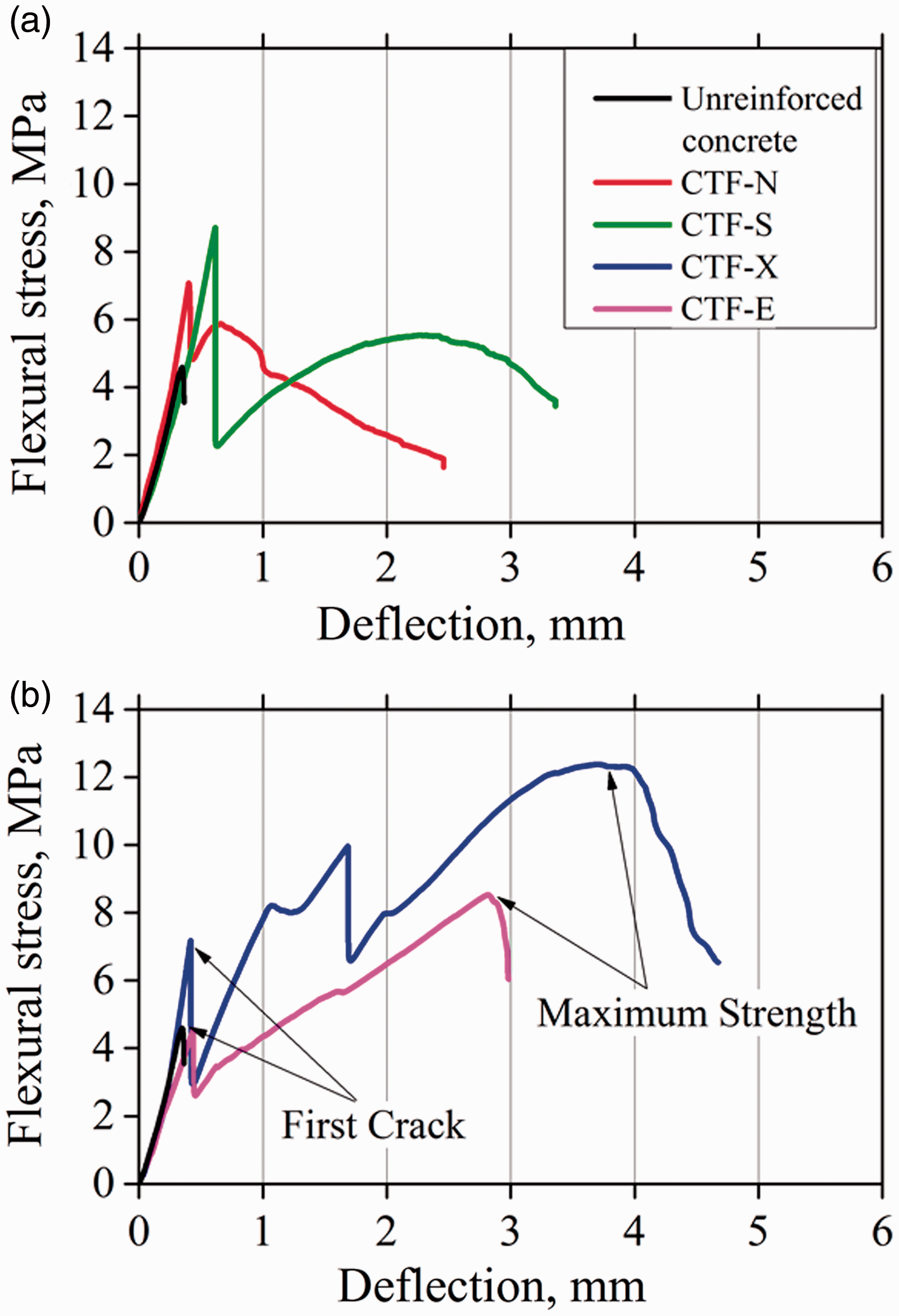
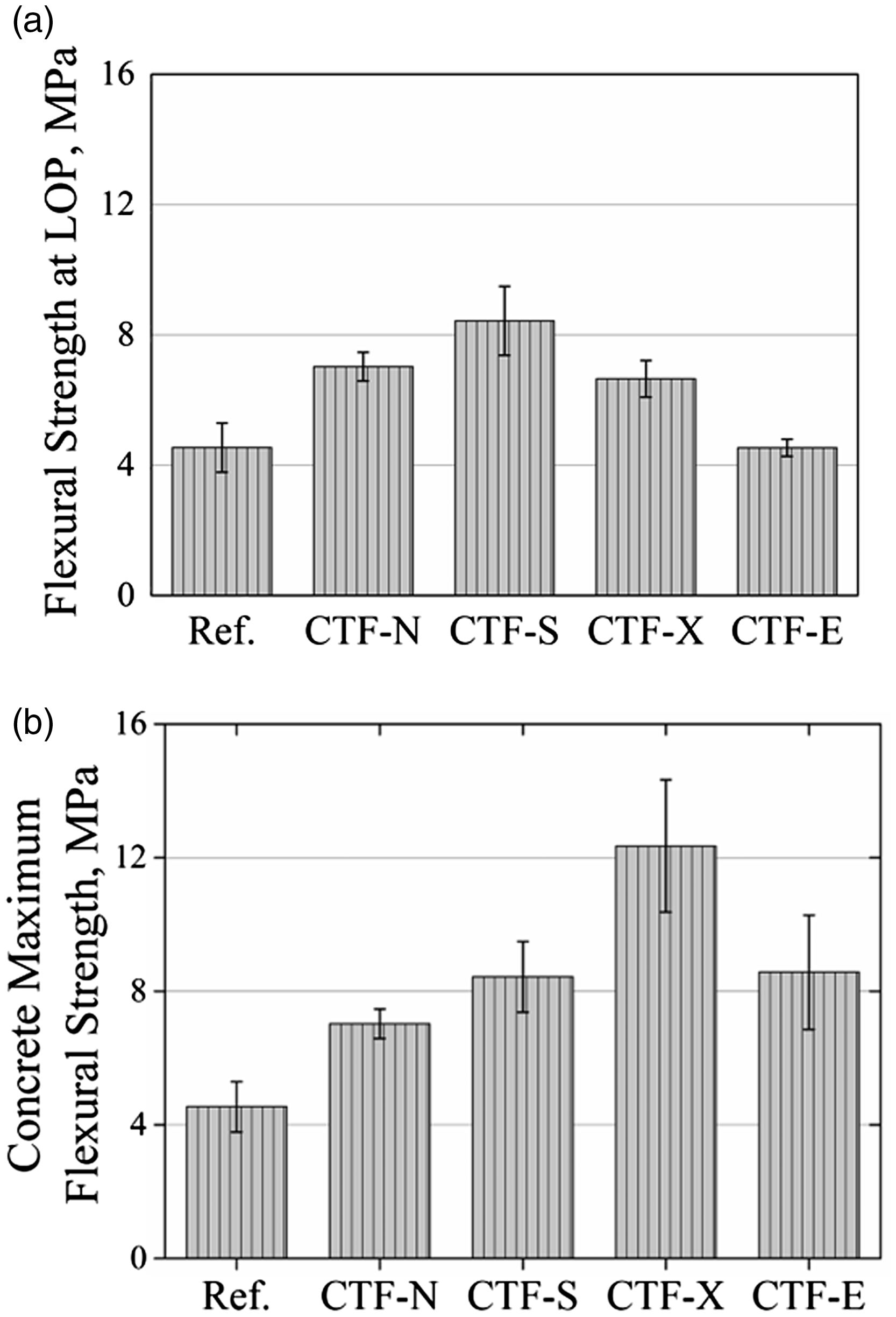
Analysing these results shows that the samples of cement composites reinforced with the non-coated (CTF-N) and silicate (CTF-S) fabrics have a lower bending strength. However, as seen from the curves in Figure 7(a), the first peak in the graph is achieved at very high stresses of bending for the CTF-N and silicate CTF-S samples. The strength at the LOP in these two samples is equal to withstands peak sample. The samples of cement composite CTF-N and CTF-S were destroyed at the first crack because of strong bonding between the fabric and matrix. Samples of cement composites with the XSBR (CTF-X) and epoxy resin (CTF-E) coating achieve a value of the first peak of about 0.49–0.53σmax. The relationship between the concrete flexural strength and the strength corresponding to LOP depending on the coating type is shown in Figure 9. Further, with increasing deflection, load increases because of the resistance of the rovings. In this behaviour, the coating plays a significant role in achieving the maximum strain at rupture. In the case of the CTF-X and CTF-E samples, the reinforced concrete matrix continues to resist much longer compared with the CTF-N and CTF-S samples. This is clearly seen in Figure 7(a) and (b), where the maximum deflection is approximately 3 mm for the CTF-E sample and exceeds 3 mm or the CTF-X sample. This capacity of maintaining the form and performance without fracture at very large strains can be utilized in critical application areas, such as those associated with the seismic resistance of buildings and constructions. It should be noted that this material characteristic is inadequate to prevent the failure in these critical applications. However, the use of such materials will sustain the residual load-bearing capacity for a longer time.
Relationship between strength at the limit of proportionality and maximum flexural strength of cement composite.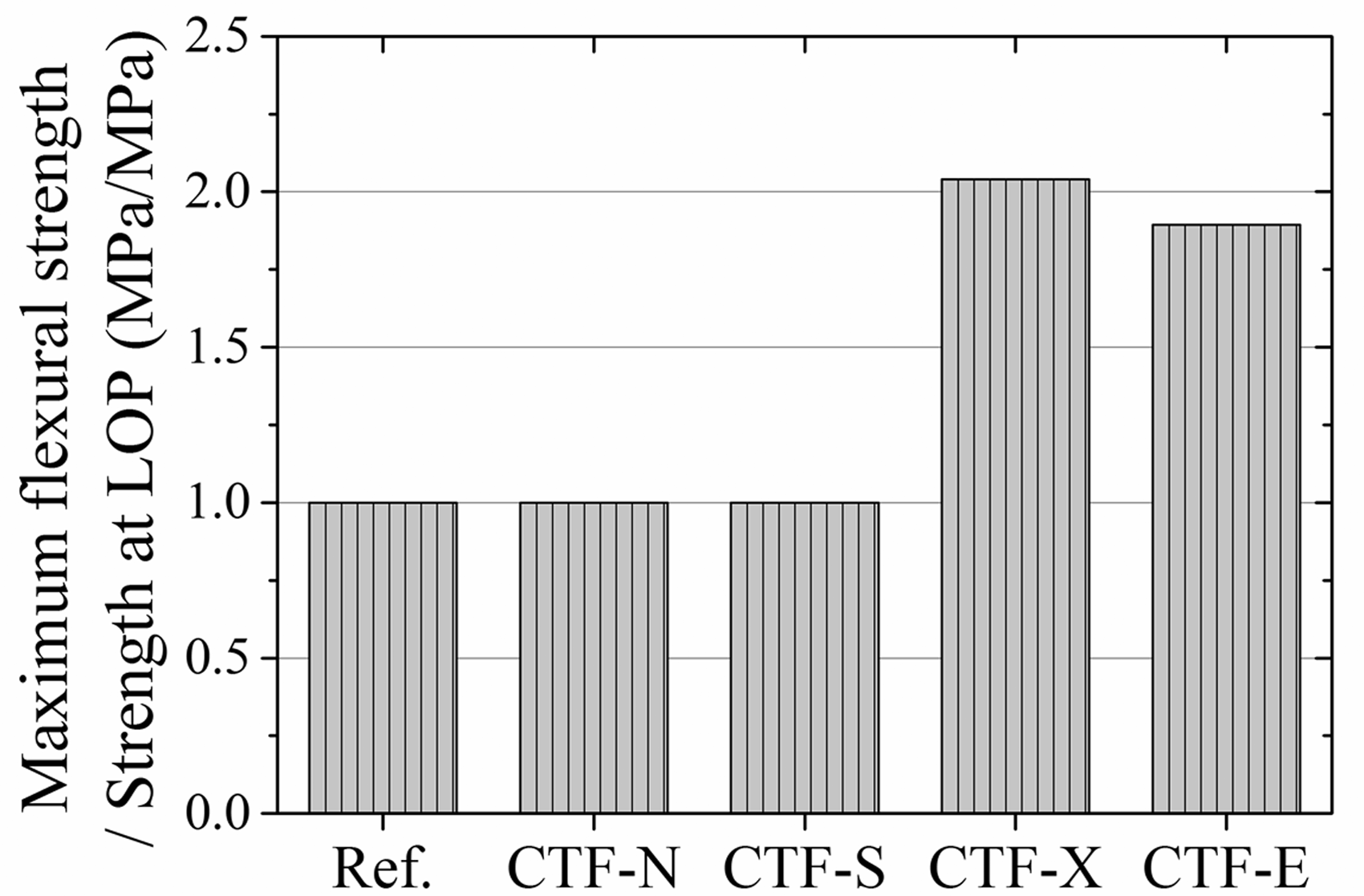
Figure 10 illustrates the crack behaviour of different coated fabric types. For the non-coated (CTF-N) and silicate (CTF-S) fabric-reinforced composites, a single crack occurs, as shown in Figure 10(a). In the case of the XSBR (CTF-X) and epoxy resin (CTF-E), multiple cracks are produced as can be seen in Figure 10(b), respectively, whereas in the case of the epoxy resin (CTF-E), this effect is more pronounced.
Examples of crack behaviour in composites without and with different coating types: (a) CTF-N and (b) CTF-E sample.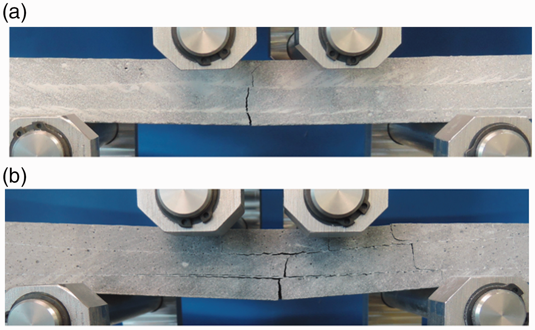
Summarizing the above results of the four-point bending test, it is concluded that the coating type defines mainly the flexural behaviour of samples. The concrete samples reinforced with non-coated fabric and potassium silicate coating provided a better bond with the cement matrix. In this case, the non-coated fabric provided adhesion due to better permeability of cement matrix. Without coating, the cement can directly penetrate between the filaments and grow crystals during hydration to perform a cross-link. However, this effect is limited due to the limited penetration depth. Whereas in the case of reinforcing potassium silicate coated fabric, an increase in the strength at the LOP due to better penetration of cement matrix into the glass roving was observed. Potassium silicate is similar in its chemical composition to the concrete. During curing of the concrete, the crystal growth is not blocked as in the case of polymers but on the contrary, the crystal growth rate is enhanced. Thus, it is likely that the concrete penetration depth is increased. The potassium silicate does not penetrate the roving completely and is randomly distributed among the cross-section as seen in Figure 6. Therefore, the composite strength of the roving and the coating is lower compared to the polymer coatings. Although the amount of coating is the lowest, the potassium coating showed very good bonding to the concrete matrix. This is due to similar chemical nature of the coating and the cement. As a result, the composite properties of the reinforced concrete were comparable, resulting in the highest strength at the LOP. The polymer coatings affirm to the sizing of the rovings and form a good adhesion with the fibres. Therefore, the tensile properties increased with the applied coating. The coating effect was similar to the mechanical behaviour of fibre reinforced plastics. 35 Due to the polymer matrix, the load was distributed more evenly among the filaments and higher loads were achieved. The epoxy resin formed a very smooth, hydrophobic surface with very little adhesion to concrete. The load was transferred within the concrete composite only by the firm locking of the grid and the surrounding matrix. As a result, the epoxide coated fabrics had comparably low strength at the LOP due to the bonding between concrete and epoxide and a high maximum strength due to the good bonding between epoxide and fibre.
Statistical analysis
Statistical analyses of the properties of coated fabrics and cement composites were conducted using one-way ANOVA for significant differences at the 0.05 significance level. Tukey HSD post hoc test was performed to examine the significance of the differences between the average values of tensile characteristics of coated fabrics and flexural characteristics of composite samples.
One-way ANOVA test results.
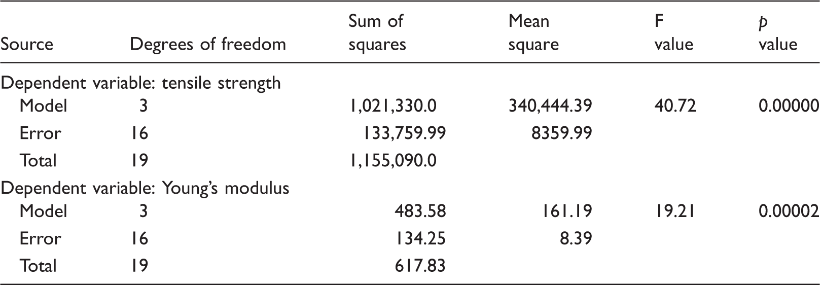
ANOVA: analysis of variance.
One-way ANOVA test results.
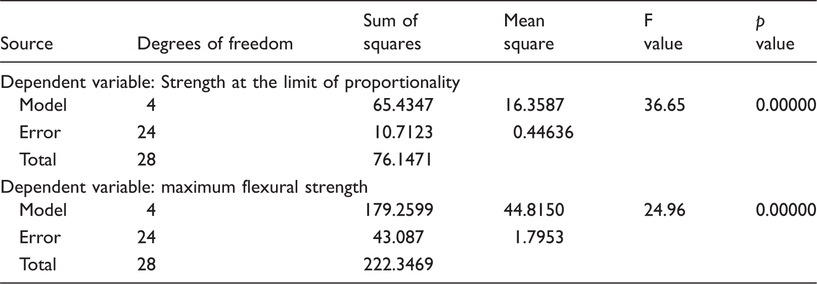
ANOVA: analysis of variance.
Tukey HSD post hoc test results.
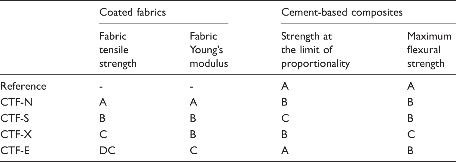
Ref.: unreinforced concrete; CTF-N: non-coated fabric; CTF-S: coated fabric with the silicate; CTF-X: coated fabric with XSBR; CTF-E: epoxy-coated fabric; HSD: honest significant difference
Note: The same letter indicates that the difference of the means is not significantly different at the 0.05 level.
Efficiency of coated warp-knitted reinforcement in cement composites
In order to evaluate the RE of the investigated materials, the coefficients that show an increase in composite properties relayed to original material may be used. The RE was calculated as
Figure 11 shows the coefficient of RE with respect to the original non-reinforced cement sample. As can be seen, the sample of non-coated fabric reinforcement has minimum efficiency by a factor not exceeding 1.55. For the data samples of coated fabric cement composites, the RE factor was greater than 1.86 in terms of MFS. However, the cement composite reinforced with CTF-X and CTF-E fabrics showed the lowest strength efficiency in terms of strength at the LOP, although these coated fabrics possessed the highest TS. The obtained results indicate a significant improvement in RE. In addition, some positive effect can be found in deformation behaviour of cement composites.
Reinforcement efficiency.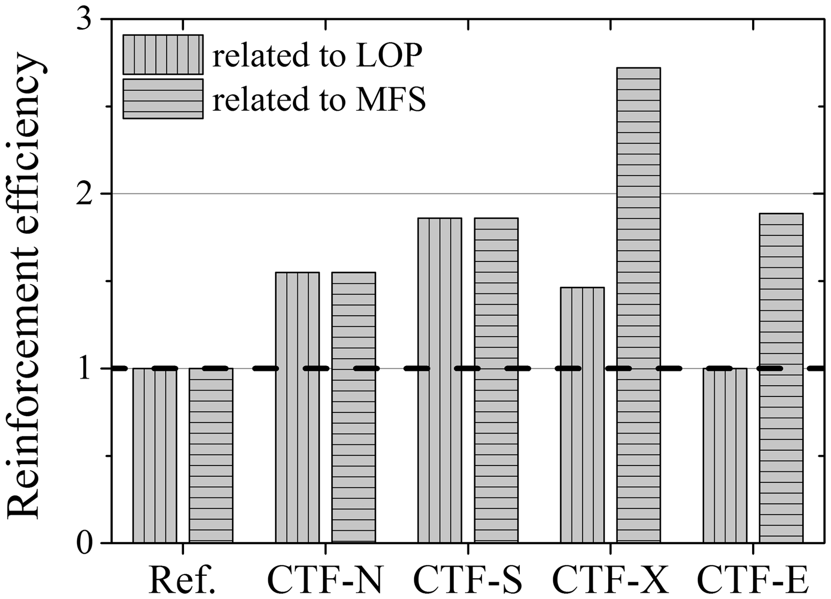
Based on these results, it was concluded that the potassium silicate coating (CTF-S) provided better mechanical characteristics and provided an optimal effect of reinforcing efficiency in terms of the strength at the LOP. Besides, this type of coating has a lower weight and low cost. The remaining two coating types (CTF-X and CTF-E) led to a weight increase and lower fabric adhesion. The surface bonding was divided in bonding between fibre and coating and bonding between reinforcing textile and concrete. The strength at the LOP resulted from the stress distribution within the concrete composite. A good adhesion between the reinforcing textile and the concrete led to an even stress distribution resulting in multiple cracks and higher strength at the LOP. The potassium silicate coating led to high strength at the LOP – even with the lowest amount of coating applied to the highest values as compared to polymer coatings. The polymer coatings formed a good adhesion within the roving that led to higher values in terms of maximum strength.
Conclusions
Experimental work has showed that the type of coating has a significant impact on the properties of cement-based concrete composites. In order to improve the load-carrying capacity of composites, weft inserted warp-knitted fabrics made of AR glass rovings are produced. The influence of coating type on properties of the fabrics and cement composites reinforced with them is described in this paper. It is observed that the coating type significantly affects the properties of the fabrics and cement composites based on them. In general, coated fabrics show better strength characteristics as compared to non-coated fabric. However, the flexural behaviour of the different composite samples varies considerably. Cement composites reinforced with fabrics with XSBR (CTF-X) and epoxy (CTF-E) coating demonstrate very high residual strength and low strength at the LOP. This can be explained by the high TS of the reinforced fabrics that are able to withstand higher deformation than concrete. Samples CTF-N and CTF-S provide very high adhesion between the fabric and the cement matrix, which leads to instantaneous fracture of the cement composite. The strength at the LOP is equal to the maximum cement composite strength.
In order to confirm the observed effects, statistical analysis was conducted. One-way ANOVA for significant differences is performed. The results showed that the effects of coating type are very pronounced at a significance level of 0.05. Statistical analyses of the tensile properties of the cement composites are conducted using Tukey HSD post hoc test to examine the significance of the differences between the average values of tensile characteristics of coated fabric samples and flexural characteristics of the composite samples.
Footnotes
Declaration of Conflicting Interests
The author(s) declared no potential conflicts of interest with respect to the research, authorship, and/or publication of this article.
Funding
The author(s) disclosed receipt of the following financial support for the research, authorship, and/or publication of this article: This work was supported by German Academic Exchange Service (DAAD).