
Abstract
A computationally efficient multiscale modelling approach for predicting impact damage within fabric reinforced laminated composites is presented. In contrast to common ply-level approaches, the topology of a multi-layered fabric reinforced laminate is resolved at tow-level for a sub-domain embedded in a shell layer with homogenised representation of the laminate. The detailed sub-domain is entirely modelled using shell elements, where material nonlinearities such as damage and plasticity-like behaviour of the tows, inelastic behaviour of unreinforced resin zones up to failure and delamination between plies are accounted for. To exemplify the capabilities of the approach, an explicit finite element simulation of a laminated plate consisting of eight carbon fabric reinforced epoxy plies with eight harness satin weaving style in a drop weight impact test setup is conducted. The spatial and temporal distribution of intra- and inter-ply damage is predicted and the total energy absorption by the plate, as well as the contributions of individual damage mechanisms are evaluated. The predictions show very good agreement with corresponding experimental data from the literature and give insight into the impact behaviour of the laminate beyond the capability of usual experiments. The new approach allows to resolve the stress concentrations due to fabric topology in detail. Compared to common ply-level approaches this is reflected in different predicted energy absorptions per mechanism although, the total energy absorption hardly differs. This is especially important when the post impact behaviour of laminates is predicted as it is strongly influenced by the extent of the individual damage mechanisms.
Keywords
Introduction
Laminated composites are advantageously used in many lightweight applications, ranging from aerospace structures over automotive components to sports equipment. Besides the high stiffness-to-weight and strength-to-weight ratios, these materials show good environmental and fatigue resistance as well as good formability during manufacturing. However, fibre reinforced polymer (FRP) composites exhibit a complex damage and failure behaviour involving various mechanisms such as delamination, matrix cracking, fibre rupture and plasticity-like effects. The general behaviour of laminated composites subjected to impact is summarised in the review papers Davies and Olsson 1 and Bibo and Hogg. 2 Experimental testing of the impact behaviour of FRPs is very time consuming and expensive and, in most cases, only information on the overall impact behaviour is gained. Hence, predictive tools such as simulations by means of the finite element method (FEM) are needed for an efficient assessment of FRP structures subjected to impact.
The simulation of impact on fibre reinforced composite laminates has been studied extensively within the literature.3–8 These papers focus on the simulation of impact tests on multidirectional laminates consisting of unidirectionally (UD) fibre reinforced plies with impact energies up to 40 J. The simulations feature explicit time integration schemes to predict the dynamic impact response. All the models use sub-laminate-level or ply-level based modelling approaches, where the laminate is discretised by three-dimensional continuum elements3–7 or continuum shell elements. 8 The interfaces are modelled by cohesive zone elements (CZEs). Specific continuum damage mechanics (CDM) constitutive models are applied to model damage and failure within the UD plies. Additionally, discrete interface elements within the plies can be used to account for matrix cracking.9,10
Many applications, however, feature fabric reinforced laminates. One way of modelling woven composites is to consider the ply as homogeneous orthotropic material, similar to the approach typically applied for UD composites.11–13 The laminate is modelled as a stack of sub-laminates represented by individual layers of shell elements. The interfaces between the sub-laminates are modelled by a traction-displacement based contact formulation. Another energy based CDM approach for modelling impact on woven composites at the ply level is presented in Iannucci and Willows. 14 Schwab et al. 15 presents a shell element based ply-level approach for modelling the intermediate velocity/mass impact behaviour of woven composite laminates up to complete perforation. It features exceptional numerical efficiency and is directed towards the application to large composite structures. 16
The homogeneous representation of the woven plies, however, neglects effects arising from the fabric topology such as fluctuations of the stress and strain fields. These fabric topology induced effects, consequently, influence the damage and failure behaviour of an impact loaded laminate. Some modelling approaches discretise individual bundles of fibres in order to simulate the high velocity impact behaviour of a single layer of dry fabric.17,18 Strategies for modelling the topology of polymer/fabric plies at the level of individual tows are presented in Barbero et al. 19 and Lomov et al. 20 Since 3D continuum elements are used for the discretisation, the complexity of these models restricts the range of application to the static analysis of periodic unit cells. A shell element based approach for modelling periodic unit cells of textile composites at tow-level is proposed in Gager and Pettermann.21,22 This approach is applied to static analyses of woven and braided plies and proves to be of exceptional computational efficiency while providing accurate results. Another approach for modelling the topology of the fabric reinforcement is presented in Pascal et al. 23 There, the interwoven topology of a five harness satin weave is simplified by an approximation with rod and shell elements to simulate low to medium velocity impact.
To the authors’ knowledge, however, there are no numerical investigations of the impact response of fabric reinforced laminates which account for the fabric topology in a detailed way. Moreover, numerical predictions on the effect of the weaving pattern on the impact behaviour and the associated energy absorption of a fabric reinforced laminate have not yet been reported within the open literature.
This paper presents a strategy for modelling impact on multi-layered fabric reinforced laminates while resolving the fabric topology in a detailed way. It is efficient enough to allow for the simulation of the highly dynamic, nonlinear behaviour of woven composite coupon specimens under impact loading with reasonable computational effort. Thereby, the topology of the laminate is modelled at the tow-level for a sub-domain in the proximity of the impact zone, which is embedded in a region with a homogenised representation of the laminate. The modelling approach is exemplified by numerical simulations of a rectangular laminated composite plate with quasi-isotropic layup in a drop weight impact test setup. Results from accompanying experiments are used to verify the numerical model. The effect of different weaving styles, i.e. different degrees of tow undulation, on the energy absorption of the laminate is investigated based on the present model’s predictions. Moreover, the effect of the length scale of the geometrical discretisation on the predicted impact behaviour of woven laminates is investigated by comparing the results obtained using the present tow-level modelling approach with results from a shell element based ply-level modelling approach. 15 The simulations are realised using the explicit FEM code Abaqus/Explicit v6.14 (Dassault Systemes Simulia Corp., Providence, RI).
Modelling approach
Fabric reinforced laminates exhibit complex topologies leading to inherent fluctuations in the stress and strain fields. Within this paper, the fabric topology is resolved by discretising individual tows within a laminate. This way, the influence of the fabric topology on the damage and failure behaviour of laminated fabric composites is accounted for.
Discretisation of the fabric topology
A fabric reinforced laminate consists of several layers comprising two main constituents, i.e. resin impregnated bundles of fibres (tows) and unreinforced resin zones (matrix pockets). A shell element based modelling strategy is utilised to discretise the fabric topology, which represents an extension of the approach presented in Gager and Pettermann.
21
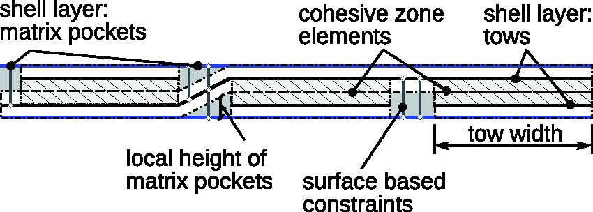
Thereby, the tows as well as the matrix pockets are discretised by individual layers of shell elements, where the following geometrical idealisations of the fabric topology are applied. The weaving pattern is assumed to be perfectly periodic, the tow undulation path is modelled piecewise linear and the tow cross-section is assumed to be rectangular and uniform along the undulation path. A schematic of the idealised geometry of a single ply is given in Figure 1 (left), where a section of a woven fabric reinforcement, as modelled by the present approach, is depicted. First, the modelling of a single ply is discussed. Considering the shell representation of the tows, the corresponding reference planes are located at the tow mid-planes. The matrix pockets are modelled by two shell layers with the corresponding reference planes located at the top and bottom of the ply, cf. Figure 1 (right), and cover the whole top and bottom surface. The shell thickness is varied according to the local geometry as illustrated in Figure 2. Where the tows touch the top or bottom surface, the matrix pockets are modelled with a thickness of 10−6 mm. In the areas shaded in grey they possess the corresponding physical thickness. As the shell layers representing the tows and matrix pockets are not connected directly, appropriate coupling conditions have to be utilised. The interface between touching tows (i.e. at tow-tow crossings) is modelled by CZEs with finite geometrical thickness, as illustrated in Figure 1 (middle) and Figure 2. This way, the shell layers representing individual tows are properly connected to each other and, provided that appropriate constitutive laws are applied, debonding of individual tows can be modelled. The top and bottom matrix shell layers are coupled to the tows using surface based constraints, see Figure 2. Thereby, the nodes on the slave surface (matrix layers) are constrained to have the same motion as the closest point on the master surface (tows), taking into account the local shell thickness as well as the shell kinematics.
24
Left: Schematic of an eight harness satin fabric ply as modelled by the present approach (showing tows only). Middle: Coupling of individual tows via CZEs at tow-tow crossings. Right: Cutaway view of a single ply. The shell thickness is rendered in all figures. Schematic of the coupling between the individual shell layers representing the tows using cohesive zone elements and the coupling of the shell layers representing the tows to the shell layers representing the matrix by surface based constraints, respectively.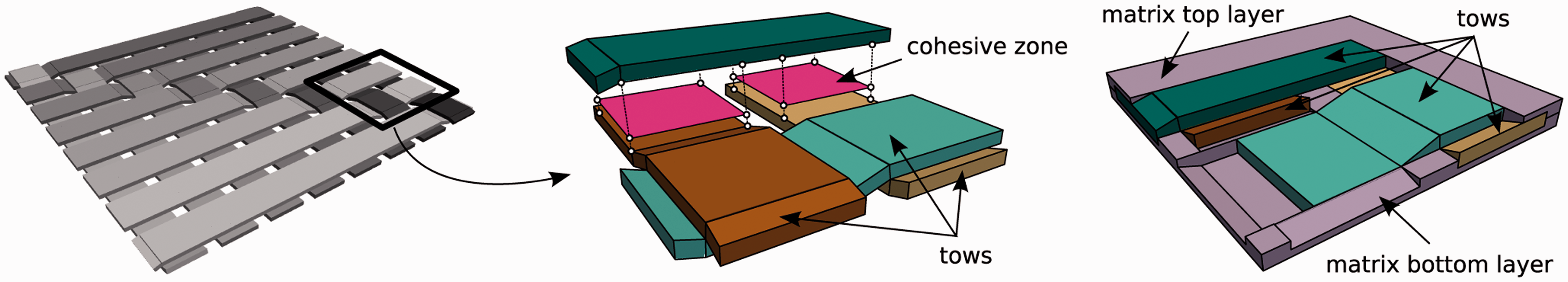
The extension to a laminate comprising several plies is straightforward. Zero thickness CZEs are introduced between surfaces of adjacent plies where surface based constraints are used to couple the CZEs to the corresponding ply surfaces, cf. Figure 3. This way, arbitrary stacking sequences can be modelled and, provided that appropriate constitutive laws are applied, delamination between plies can be accounted for.
Expanded schematic of the composition of a laminate comprising several plies. The shell thickness is rendered.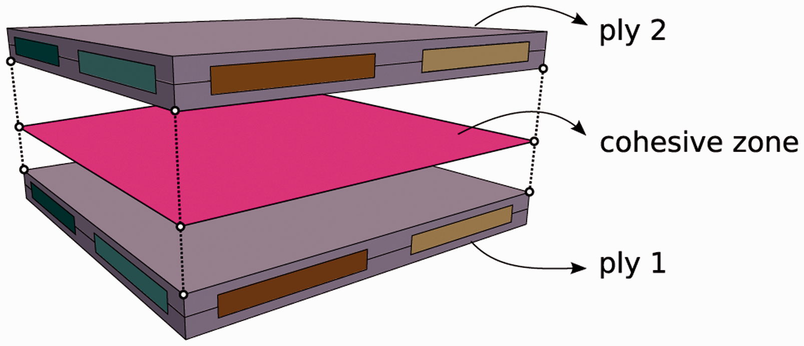
Due to the geometrical idealisations of the fabric topology, the modelled tow volume fraction is smaller than the tow volume fraction in a real fabric reinforced ply, where nesting and other irregularities are compacting the topology. This circumstance has to be taken into account when the mechanical response of some real fabric ply shall be predicted, as the overall fibre volume fraction (FVF) of the model needs to match the real FVF. In order to achieve corresponding FVFs with the proposed modelling approach, a scaling procedure for the tow material properties is applied.25,26
One aspect of the explicit FEM solver Abaqus/Explicit is that every element within the computational domain has to be assigned some mass density. Hence, also the interfaces represented by CZEs need to be assigned some mass density and, therefore, part of the nominal mass of the tows and matrix pockets is attributed to the interfaces while ensuring the correct representation of the laminate mass. As Abaqus/Explicit uses lumped mass matrices, the nodal masses remain unchanged and the dynamic behaviour of the laminate is retained, regardless of the actual mass distribution between shell elements and corresponding CZEs.
It shall be noted that the pre-processing step for the generation of such a FEM model is fully scripted so that various weaving patterns and laminate stacking sequences can be generated in an automated way.
Constituents’ constitutive modelling
The tows are treated as homogeneous orthotropic plane stress material where an energy based CDM approach is utilised to account for tensile and compressive damage along the tow direction, as well as along the transverse direction of the tows. Furthermore, plastic deformation due to shear is accounted for. The described behaviour is modelled using a built-in VUMAT user subroutine, 27 which is readily available within the FEM package Abaqus/Explicit v6.14. A summary of this material model is given in Schwab et al. 28
The mechanical behaviour of the matrix pockets is modelled as isotropic elastic-plastic with isotropic strain hardening. The linear Drucker–Prager plasticity model 24 is applied, being a typical choice for polymeric resins.26,29,30 In order to account for damage and failure within the matrix pockets, additionally, ductile damage behaviour is assigned.
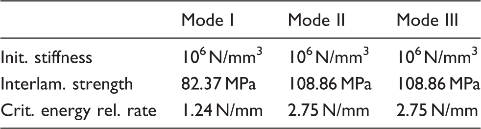
The constitutive response of the ply–ply and tow–tow interfaces is modelled using the Abaqus built-in traction-separation based constitutive model for CZEs. 24 The normal and shear traction components are assumed to be uncoupled within the elastic range. Damage initiation is predicted using a criterion based on the quadratic interaction of interface tractions. Damage progression is driven according to the corresponding critical energy release rates of the interface, where a linear softening relation based on an effective displacement is assumed. Mixed-mode conditions are accounted for using the criterion proposed by Benzeggagh and Kenane. 31
The stiffness degradation associated with the damage models used within the tows, matrix pockets and interfaces can lead to excessive element distortions and further numerical difficulties. In order to overcome these issues, element deletion 24 is utilised. Thereby, a shell element of a tow is deleted when both damage variables, i.e. damage along the tow and damage transverse to the tow, reach a value of 0.99. A shell element of the matrix pockets is deleted when the corresponding damage variable reaches a value of 1.0. Finally, CZEs belonging to the ply–ply or tow–tow interfaces are deleted when the corresponding damage variable reaches a value of 1.0.
It shall be noted that all necessary material parameters can be determined from coupon experiments which are independent of any experimental impact test. Hence, no inverse calibration needs to be conducted and the predictive capability of the model is ensured. Moreover, all but one of these experimental setups are standardised. Only the determination of the intra-ply critical energy release rates is still subject to research, where an overview of proposed methods is given in Laffan et al. 32
Multiscale embedding approach
The tow-level modelling of the fabric topology, as described above, necessitates the use of a shell element based discretisation in order to get FEM models with a reasonably low number of degrees of freedom (DOFs). However, simulations of whole coupon specimens entirely discretised using such a tow-level modelling approach are still very demanding in terms of computational resources. Considering the case of transverse impact, the domain where material nonlinearities are encountered is limited to the region in the proximity of the impact zone. Therefore, it is justified to limit the domain with tow-level discretisation of the fabric topology to this region and use some less detailed (i.e. homogenised) representation for regions remote from the impact zone. This way, the number of DOFs is decreased considerably while maintaining a sufficiently high resolution to capture the nonlinear mechanisms within the fabric reinforced plies.
Within the present work, the tow-level domain is surrounded by a single layer of shell elements with layered section definition representing the plies of the laminated composite as homogeneous orthotropic elastic material, as illustrated in Figure 4. The elastic properties of the plies within the surrounding (embedding) domain are chosen to be identical to the homogenised properties of the plies within the tow-level domain in order to yield the corresponding mechanical behaviour. These are obtained using the numerical homogenisation approach presented in Gager and Pettermann
21
in combination with symmetry boundary conditions in out-of-plane direction. These symmetry boundary conditions are introduced to prevent warping which occurs for a single free-standing fabric ply but is suppressed in a stack of laminated plies. Consequently, the homogenised properties of a fabric ply within a laminated composite are different to those of a single one.
Embedding of a patch with discretised topology of a fabric reinforced laminate (matrix pockets are not shown) in a homogenised shell region.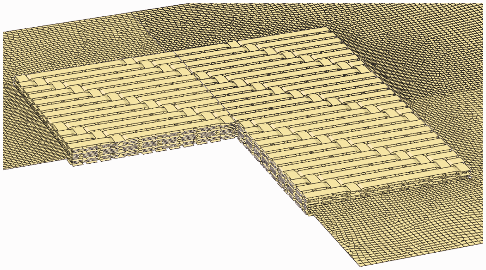
The size of the tow-level domain is chosen according to the spatial extent of the arising material nonlinearities as they shall be contained entirely within the tow-level domain.
The edges at the transition between the two domains are coupled according to shell kinematics, so that spatial offsets in thickness direction are taken into account appropriately. Therefore, so-called edge surface based tie constraints 24 are used. The resulting multiscale shell-to-shell coupling is particularly favourable in terms of coupling interferences as the element kinematics are identical in both domains. Nevertheless, to avoid premature damage accumulation possibly arising due to coupling interferences, elastic behaviour of tows and matrix pockets is modelled within a small region at the transition between the tow-level domain and the embedding domain. Note that the edge surfaces which are going to be coupled are not required to be perfectly aligned. In the case of non-aligned edge surfaces, a rigid connection is modelled within the corresponding offset distance. The composition described within this section will be referred to as multiscale embedding approach (MEA) in the following.
Contact modelling
As contact between an impactor and a target is an inherent part of any impact problem, appropriate contact modelling is particularly important in order to make conclusive numerical predictions of the impact behaviour. Within this work, all contact constraints are enforced using the general contact algorithm of Abaqus/Explicit, which utilises a penalty algorithm to compute the contact forces. 24 The associated penalty stiffnesses are chosen such that the work done by the contact forces is small compared to any of the other energy contributions. Within the present simulations the contact work is kept smaller than a tenth of any other energy contribution. This way, proper contact definitions are ensured.
The CZEs at the interfaces between adjacent plies and between touching tows also model the contact behaviour between the plies and tows. In regions of delaminations, however, CZEs are deleted and, thus, are no longer available to model inter-ply and inter-tow contact. Therefore, additional contact definitions between every tow and matrix layer are applied in order to prevent inter- and intra-ply penetrations. These additional contact definitions are just active in regions of delamination, which is ensured by scaling the thicknesses of tow and matrix layers used within the contact calculation by a factor of 0.95. It shall be noted that frictionless behaviour is assumed for inter- and intra-ply contact.
Application example—Verification
The described MEA is exemplified by the numerical simulation of a rectangular laminated composite plate with quasi-isotropic layup in a drop weight impact test setup. A verification is conducted based on a comparison of the simulation results with results from corresponding experimental tests.
15
The laminate consists of eight carbon fabric/epoxy plies with a nominal thickness of
Geometric modelling and boundary conditions
The presented MEA is utilised to model the laminated plate, where an exploded view of the modelled drop tower test setup is shown in Figure 5.
Exploded view of the modelled drop tower test setup.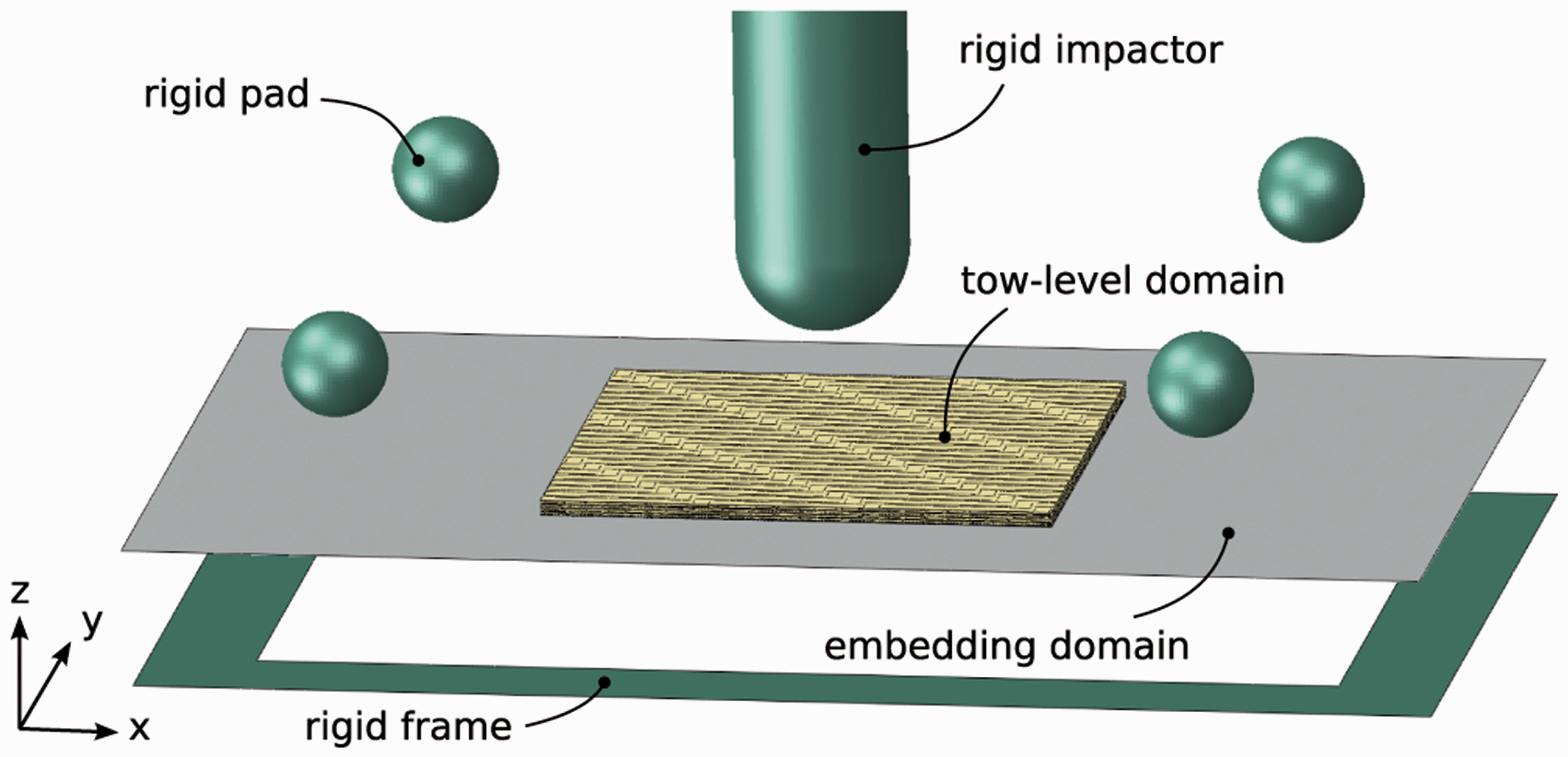
A section of the modelled (idealised) fabric topology and the corresponding dimensions which are based on real fabrics26,29 are shown in Figure 6. The quasi-isotropic [0/45/0/45]
s
laminate layup with respect to the fabric topology is modelled such that all 0 Idealised topology of the woven fabric reinforcement with dimensions in mm. Finite element discretisation of the tows, shown for a single ply of an eight harness satin weaving pattern.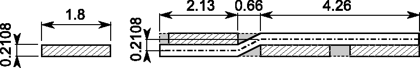
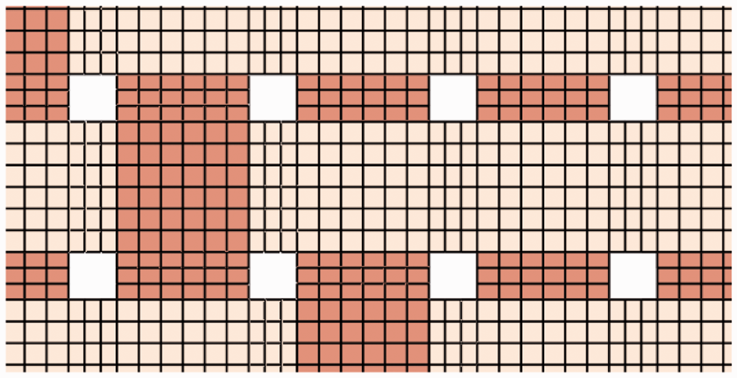
The embedding domain is discretised by a single layer of linearly interpolated, fully integrated four-noded shell elements with layered section definition, where each section corresponds to an individual ply of the laminate and features five section points for the thickness integration using the Simpson rule. The average element edge length varies from 0.5 mm at the transition to the tow-level domain to 1 mm at the outer regions.
The mounting of the laminate is modelled by four spherical rigid pads of 12.2 mm diameter at the corners of a 100 mm × 87.5 mm rectangle on top of the laminate and a rigid frame with an inner cut-out of 125 mm ×75 mm at the bottom of the laminate, cf. Figure 5. The movement of the pads and the frame is fixed in all DOFs. Contact is defined between the top surface of the laminate and the pads, as well as between the bottom surface of the laminate and the top surface of the frame, where Coulomb friction with a friction coefficient of 0.3 is modelled.
The impactor is modelled as a hemispherical rigid body and its movement is fixed for every degree of freedom except the translational movement along the z-direction, cf. Figure 5. The total mass of 2 kg of the impacting part is modelled by assigning two regions of different mass densities to the impactor. The region which comes into contact with the laminate features the mass density of steel whereas the top region of the impactor is assigned a higher mass density in order to reach the total mass. An initial velocity of 20 m/s is assigned to the impactor, resulting in an impact energy of 400 J. Frictionless contact is defined between the impactor and the top surfaces of every tow and every matrix layer.
To limit the effect of any high-frequency spurious oscillations that may occur during the simulation the Bulk-Viscosity method is used, where the Abaqus default settings are applied.
Material properties
Mass densities assigned to tows, matrix pockets and interfaces.

Note: See the text for an explanation.
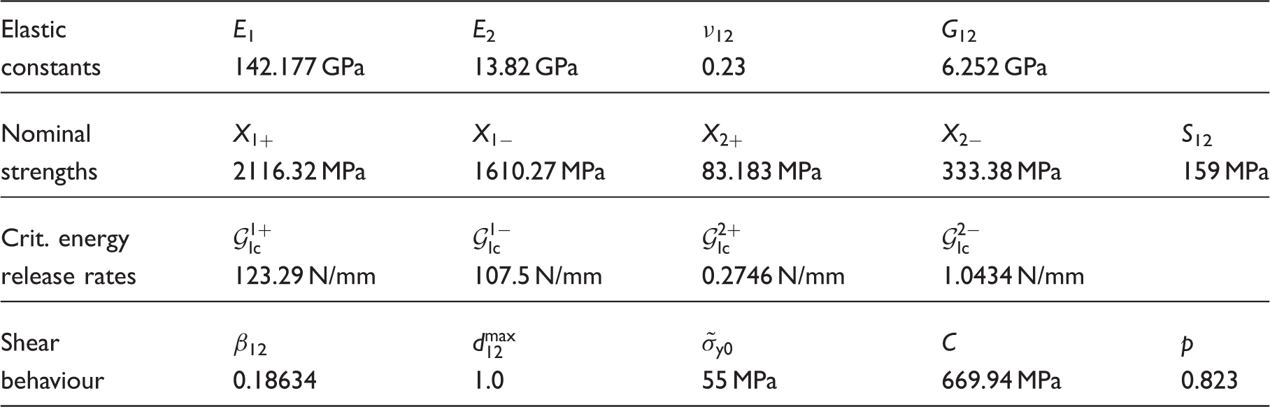
Material properties defining the constitutive response of the tows.
Material properties assigned to the matrix pockets.
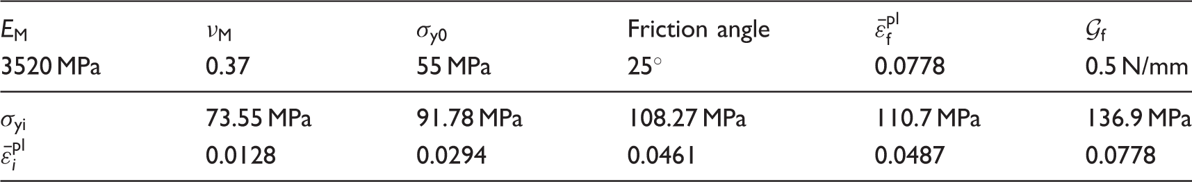
Note: See the text for an explanation.
Material properties of the homogenised plies within the embedding domain.
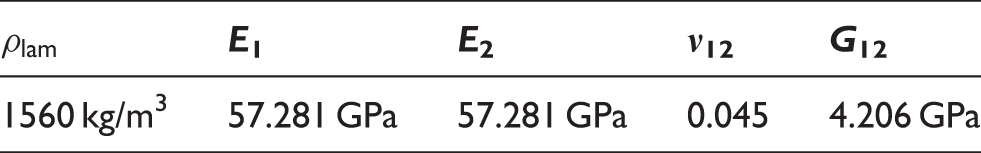
Note: The subscripts 1 and 2 indicate the tow directions.
Ply–ply interface properties describing the initial stiffness of the interface, as well as damage initiation and propagation.
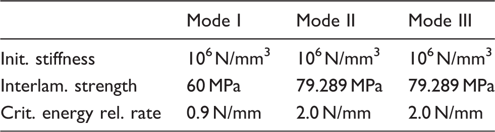
Tow–tow interface properties describing the initial stiffness of the interface, as well as damage initiation and propagation.
Results and discussion
In the following, the predictions by the MEA model are presented and compared to results from corresponding experiments. Details regarding the experimental setup are described in Schwab et al.
15
The impactor hits the plate with an initial velocity of 20 m/s and then stays in contact with the plate until it is fully perforated. This is observed for both the experiment and the impact simulation. In the following the plate is denoted to be fully perforated if no further change in the kinetic energy of the impactor can be observed, i.e. the reaction force on the impactor has vanished. Figure 8 shows the predicted and the experimentally observed failure pattern at the back face of the laminate after a 400 J impact. The predicted failure pattern depicted in Figure 8 (left) is recorded at 0.8 ms of simulation time, directly after the plate was fully perforated, whereas Figure 8 (right) shows the failure pattern after the specimen was removed from the experimental setup. Permanent deformations are not studied in the simulation as it is stopped at 0.8 ms. The simulated failure pattern compares extremely well to the experimentally observed one. In both cases the plate is fully perforated and the predicted cross shaped cracks in Figure 8 (left) in the back face of the laminate correspond very well to the experimentally observed cracks. These intra-ply cracks arise due to propagating damage within individual tows, as well as within matrix pockets. Also, some small cracks between tows within the unreinforced resin zones are predicted. Such small cracks are also visible in the tested plate, cf. Figure 8 (right).
Failure pattern at the back face of the laminated plate after 400 J impact. Left: Predicted impact response. Right: Experimentally observed response. The images are depicted at the same length scale.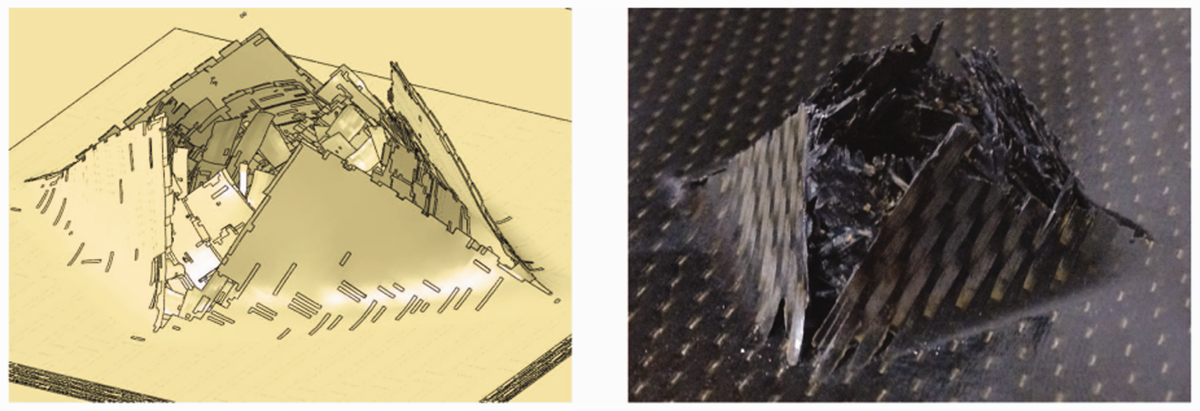
The predicted delamination pattern within the ply–ply interfaces at the end of the impact event is shown in Figure 9 (left). The shadings indicate an overlay of the delamination areas of all seven interfaces. The darker the shadings are, the more interfaces are delaminated at a specific location of the laminate. Figure 9 (right) shows the front face of the experimentally tested plate. The white lines indicate the projected delamination area as determined by an ultrasonic scan, which is also represented by the black solid lines in Figure 9 (left). As can be seen, the predicted shape and size of the projected delamination area is in very close accordance with the experimentally determined one. Hence, as far as the comparisons in Figures 8 and 9 show, the spatial distribution of intra- and inter-ply damage is predicted very well by the MEA model indicating that the corresponding damage and failure mechanisms are represented appropriately.
Left: Overlay of predicted delamination areas. A value of 0.0 indicates that no delamination is predicted, whereas 1.0 corresponds to delamination at every interface. The impactor hits the plate at x = 29.5 mm and y = 29.5 mm with respect to the depicted coordinates. Right: Projected delamination area according to an ultrasonic scan of the impacted plate. The images are depicted at the same length scale.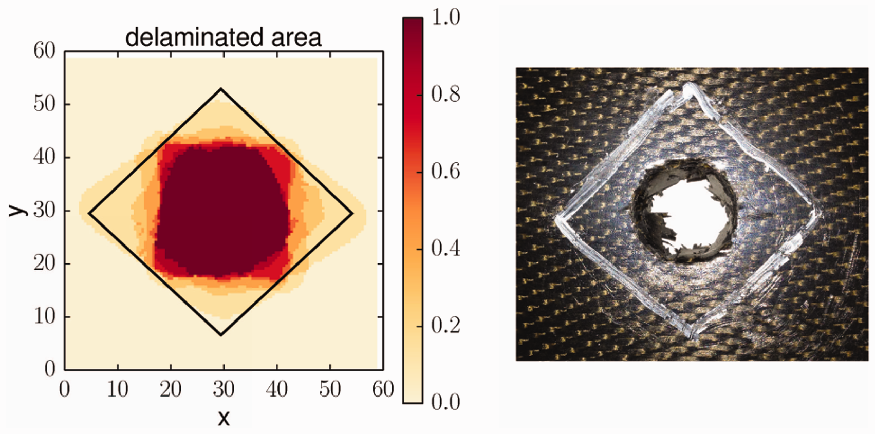
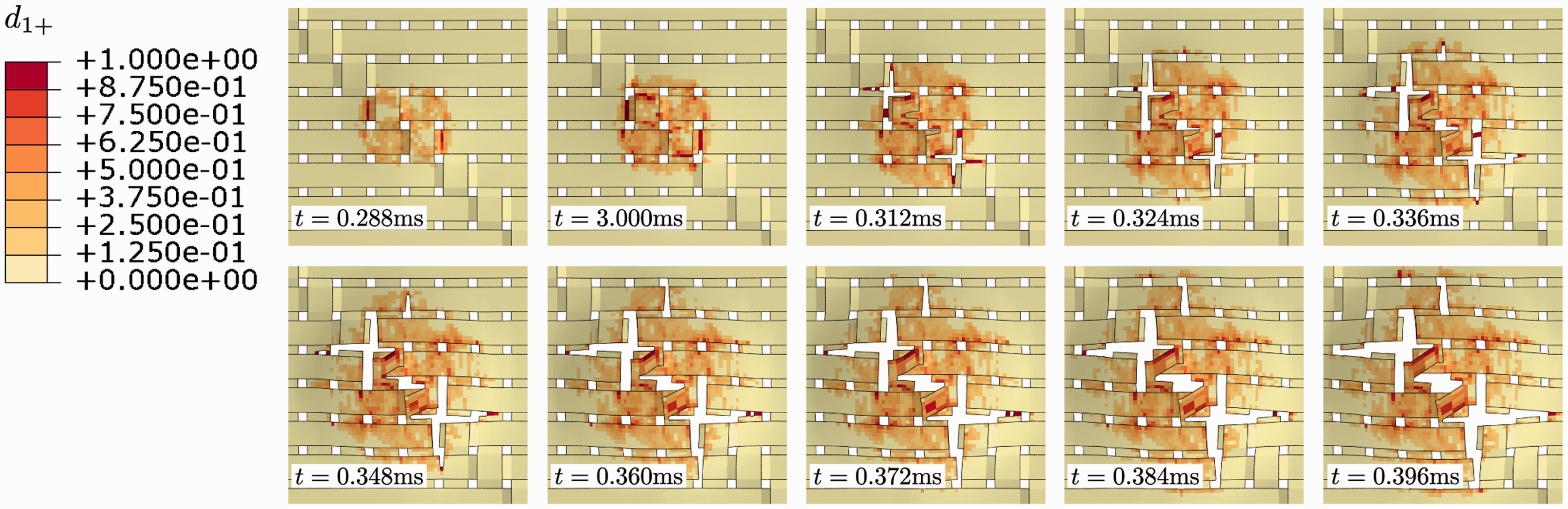
As can be seen in Figure 10 both intra- and inter-ply damage start directly under the impactor where the stresses are mainly introduced by the bending deformation of the plate. The damaged zone then grows towards the edges of the plate but stays within the tow-level domain. The distance to the interface with the embedding domain is large enough such that no influence of the coupling between the two domains on the damage pattern can be observed. The damage/fracture in the individual tows between t = 0.300 ms and t = 0.396 ms is resolved in more detail in Figure 11. Ply failure starts at the two horizontal tows directly under the impactor and then proceeds towards the neighbouring horizontal tows and the vertical tows under the impactor. The two vertical tows in the centre of the impact zone are not fully ruptured until the end of the impact simulation, although the neighbouring vertical tows have already failed, see also Figure 10.
Predicted development of the delamination Predicted damage and failure over impact time in the individual tows directly under the impactor for the ply closest to the impacted surface.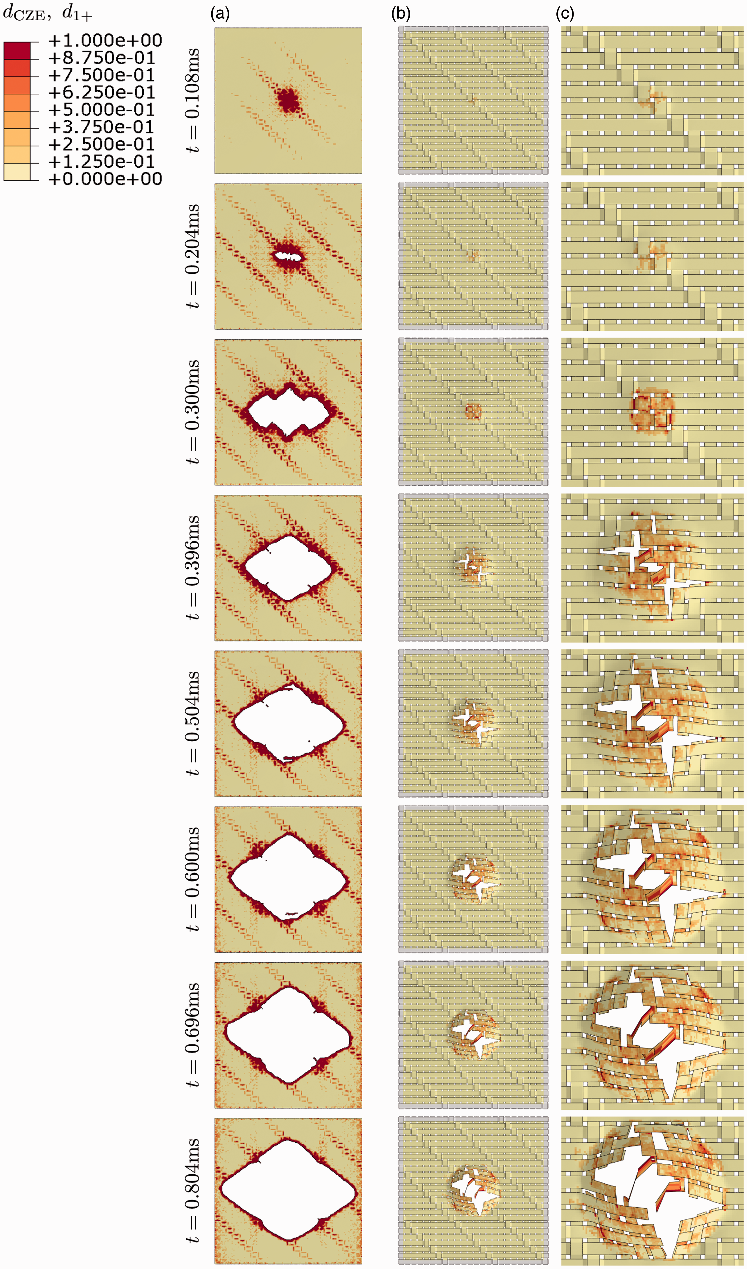
Now, the quantitative predictive capabilities of the MEA are assessed. Figure 12 (left) shows a comparison of the predicted and experimentally evaluated amount of energy absorbed by the laminate during the impact event.
Left: Comparison of the predicted and experimentally obtained energy absorbed by the laminate with respect to time. Right: Comparison of predicted and experimentally measured total force acting on the impactor with respect to time. At time t = 0 ms first contact between the impactor and the plate is observed.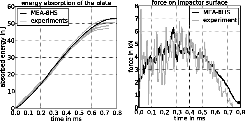
The predicted energy absorption is evaluated as the reduction of the kinetic energy of the impactor whereas the measured energy absorption is evaluated from the recorded force–time signal. The prediction matches not only the total amount of absorbed energy of the laminate but also the progression of energy absorption with respect to time very closely. Damping of spurious oscillations leads to very little energy dissipation due to viscous effects. As this energy contribution is negligible compared to the energies dissipated by the individual damage mechanisms, it can be concluded that spurious oscillations do not influence damage development. Considering Figure 12 (right), the predicted and measured total force acting on the impactor during the impact event are compared. Very close agreement is found at every instant of time throughout the impact event and the time of occurrence of the peak force, as well as its magnitude is well predicted. Note that the oscillations of the measured force–time signal are partly caused by slight elastic deformations of the impactor and that the sudden stop of the measured force–time signal at about 0.74 ms is due to the activation of the anti-rebound mechanism of the drop tower test system. These effects are not modelled within the present simulation. From the comparisons presented above it is concluded that the MEA model is able to predict the qualitative and quantitative impact behaviour of a fabric reinforced laminate to a high degree of precision. Furthermore, it is shown that the presented approach allows a detailed evaluation of individual damage mechanisms being active throughout the impact. The evaluation capabilities exceed usual experimental evaluation capabilities and as damage in the tows can be explicitly accounted for also the capabilities of standard ply-level approaches. Some more detailed evaluations of the simulation results are discussed in the following section.
The MEA model features approximately 12.5 million DOFs and the computations are conducted using a distributed memory cluster system of four standard PC workstations with, in total, 16CPUs at 3.3 GHz. In this configuration, the computation of the laminate’s impact response for a time span of 0.8 ms takes about 2.4 days.
Effect of fabric topology
Degree of tow undulation
In the following, the effect of different weaving patterns on the energy absorption behaviour is investigated based on the example of a laminate in a drop weight impact test setup, as discussed in the previous section. Further, some detailed evaluations of the simulation results, exceeding usual experimental evaluation capabilities, are discussed.
Figure 13 shows the three weaving patterns which are going to be investigated, an eight harness satin (8HS), a 2/2 twill weave and a plain weave. As can be seen, the degree of tow undulation varies depending on the weaving style. The MEA is utilised in order to study the effect of these weaving patterns (i.e. the effect of different degrees of tow undulation) on the impact behaviour and the energy absorption behaviour of fabric reinforced laminates, where the FEM modelling and simulation strategy are the same as presented in the previous sections. Thereby, the micro-geometry of the fabric, i.e. the tow cross-section and the distance between the tows, is kept identical and just the tow undulation is varied. The quasi-isotropic [0/45/0/45]
s
laminate layup with respect to the fabric topology is modelled such that all 0 Weaving patterns considered for comparison. Left: Eight harness satin. Middle: Plain. Right: 2/2 twill. Homogenised elastic properties of plies with different reinforcement weaving styles. Notes: The subscripts 1 and 2 indicate the tow directions.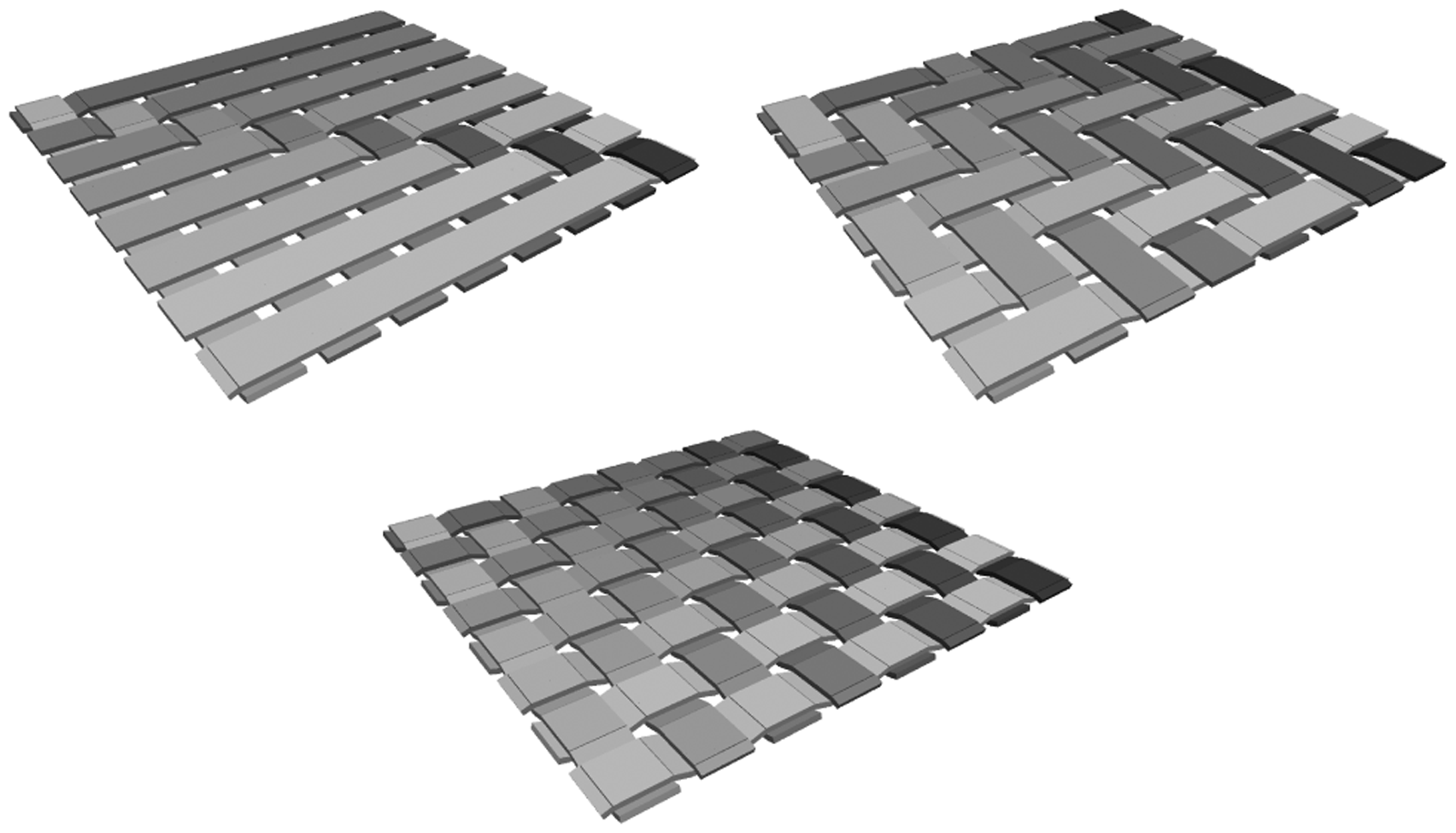
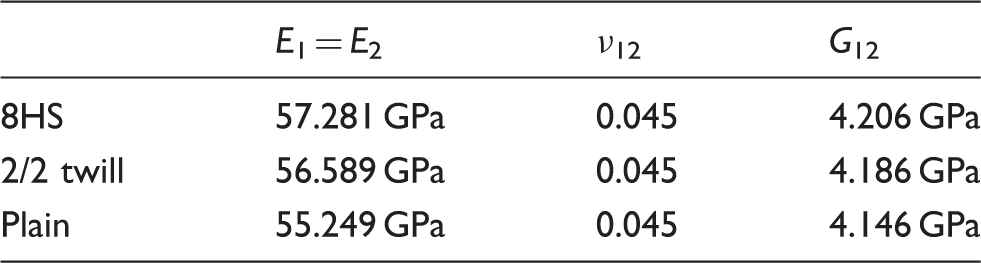
Figure 14 shows a comparison of the total energy absorbed by laminates with different reinforcement weaving patterns. The solid line corresponds to the laminate with eight harness satin fabric reinforcement, the dashed line represents the laminate with the 2/2 twill weaving pattern and the dotted line represents the laminate with the plain weaving pattern. The progression of energy absorption is almost identical for all configurations. Considering the scatter in the experimental data, cf. Figure 12 (left), the differences in the predicted total energy absorption of laminates with different reinforcement weaving pattern are very small.
Comparison of the effect of different weaving patterns on the predicted total energy absorption of the laminate.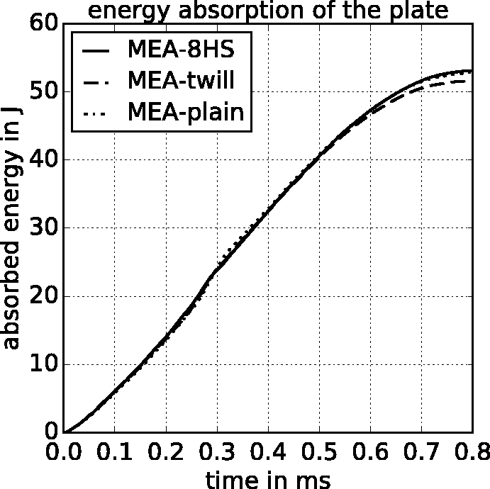
Figure 15 shows the contributions of individual mechanisms to the total amount of energy absorbed by the laminate. The bars with index “DAMAGE” identify the amount of energy absorbed by ply fracture, where the major part is attributed to tow fracture. The bars with index “PLAST” correspond to the energy absorbed due to plastic deformation within the tows and the matrix pockets. The bars with index “DELAM” represent the energy absorbed by ply–ply and tow–tow delamination. The bars “RECOV” identify the recoverable part of the absorbed energy being the sum of the plate’s kinetic energy and the elastic strain energy stored within the plate. They correspond to the elastic oscillation of the plate. As can be seen, there is no significant difference in the energy absorption of individual mechanisms with respect to the different reinforcement weaving styles. The highest contributions to the absorbed energy are predicted to arise from ply fracture and from the elastic oscillation of the laminate. The energy dissipated due to ply–ply delaminations is roughly 9 J and the energy dissipated due to tow–tow delamination is about 2 J. The energy dissipated due to plastic deformations is roughly 8 J and, thus, also represents a significant contribution. It should be noted that plastic deformations resulting from the transverse compression (out-of-plane compression) of the tows are not considered due to the plane stress assumption of the shell elements used to model the tows. Interestingly, roughly one-third of the total plastic dissipated energy is associated with plastic deformations within the matrix pockets. Note that the modelled volume fraction of the matrix pockets is slightly higher than the one in a real fabric reinforced laminate due to the applied geometrical idealisations. Concluding from Figure 15 it can be stated that all mechanisms represent a significant part of the total energy absorption. However, the degree of tow undulation does not seem to have a significant effect on the extent of any of the mechanisms.
Comparison of the effect of different weaving patterns on the predicted energy absorption of individual mechanisms at the end of the impact event.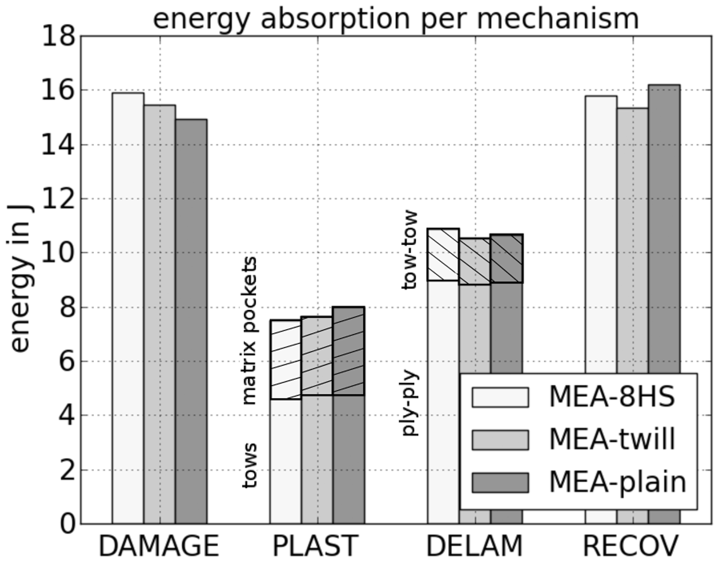
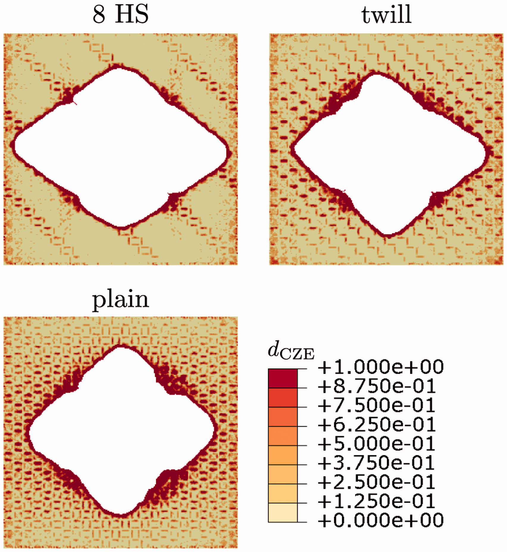
Figure 16 shows the delaminated areas within each interface, as predicted by the MEA model. A trend with delamination areas becoming larger towards the back face of the laminate is recognisable. The delaminated area within the interface closest to the back face of the laminate is significantly larger than the one within the other interfaces. This corresponds to the failure pattern shown in Figure 8, where the ply at the back face exhibits a long cross-shaped crack. It can be seen that there is almost no difference in the delaminated areas with respect to the different reinforcement weaving styles. The delamination patterns for the different fabric topologies obtained in the interface closest to the back face of the laminate are depicted in Figure 17. Not only the size of the delaminated areas is similar for the different weaving styles but also their shapes. Hence, the conclusions from Figure 15 are affirmed. However, the weaving style has an impact on the damage distribution within the interfaces. As can be seen from Figure 17 the zones with high matrix concentrations, i.e. the matrix pockets, show higher values of the damage parameter Prediction of delaminated areas within individual interfaces of the laminate after impact. Interface number seven is the one closest to the impacted surface. Delamination patterns in the interface on the back face of the laminate for the different fabric topologies at the end of the impact simulation (t = 0.8 ms).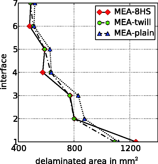
Tow-scale vs. ply-scale modelling
In the following, the effect of the length scale of the geometrical discretisation on the predicted energy absorption of a fabric reinforced laminate is investigated. Thereby, a shell element based ply-level modelling approach 15 is opposed to the proposed tow-level modelling approach (MEA). Within the ply-level approach each individual ply is modelled using a layer of shell elements and the interfaces between the plies are discretised using CZEs. 15 In contrast to the proposed tow-level approach the plies are treated as homogeneous orthotropic material and the tows and matrix pockets are not resolved. The investigations are based on the simulation results for the presented drop weight impact test setup.
Figure 18 shows a comparison of the total absorbed energy. The ply-level simulation is indicated by the dotted line and the tow-level simulation (MEA) is represented by the black solid line. As can be seen, the progression of energy absorption is almost identical for both models up to 0.5 ms after the impactor hit the laminate. Afterwards, the ply-level model predicts a slightly higher energy absorption. Considering the experimental scatter, cf. Figure 12 (left), the differences in the total energy absorption are not significant and, thus, Figure 18 indicates that the length scale of the geometrical discretisation does not influence the predicted overall energy absorption of a fabric reinforced laminate subjected to impact.
Comparison of the effect of the length scale of the geometrical discretisation on the predicted total energy absorption of the laminate.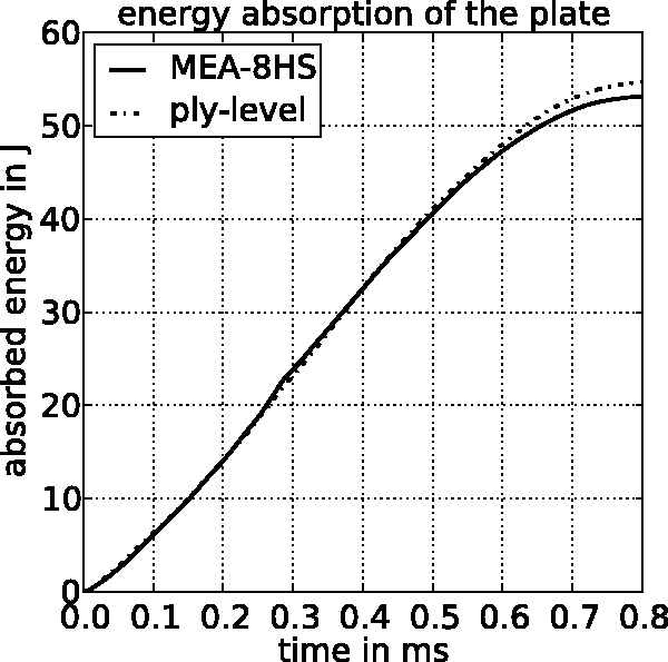
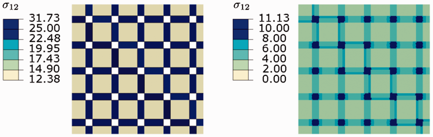
However, considering the energy absorption of individual mechanisms, cf. Figure 19, significant differences with respect to the energy dissipated due to plastic deformations (bars with index “PLAST”) are observed. The predicted plastic dissipation by the tow-level model is approximately half of the amount which is predicted by the ply-level model. The tow-level model predicts the amount of energy dissipated due to plastic deformations within a ply based on the plastic deformations within the matrix pockets and the tows. The ply-level model considers a fabric ply as a homogeneous material and, therefore resolves the plastic dissipation in a homogenised way. The fluctuations in the stress and strain fields (i.e. stress concentrations) arising due to the fabric topology are not resolved within the ply-level model which, in turn, influences the accumulation of plastic strains. Figure 20 illustrates the distribution of the in-plane shear stress component within the tows and the matrix pockets of a tow-level patch subjected to in-plane shear. The stress concentrations in regions of tow-crossings, as well as in unreinforced resin zones are clearly visible.
Comparison of the effect of the length scale of the geometrical discretisation on the predicted energy absorption of individual mechanisms at the end of the impact event. Fluctuations in the field of the in-plane shear stress component σ12 (in MPa) within a tow-level patch (eight harness satin) subjected to in-plane shear. Left: Tows. Right: Matrix pockets.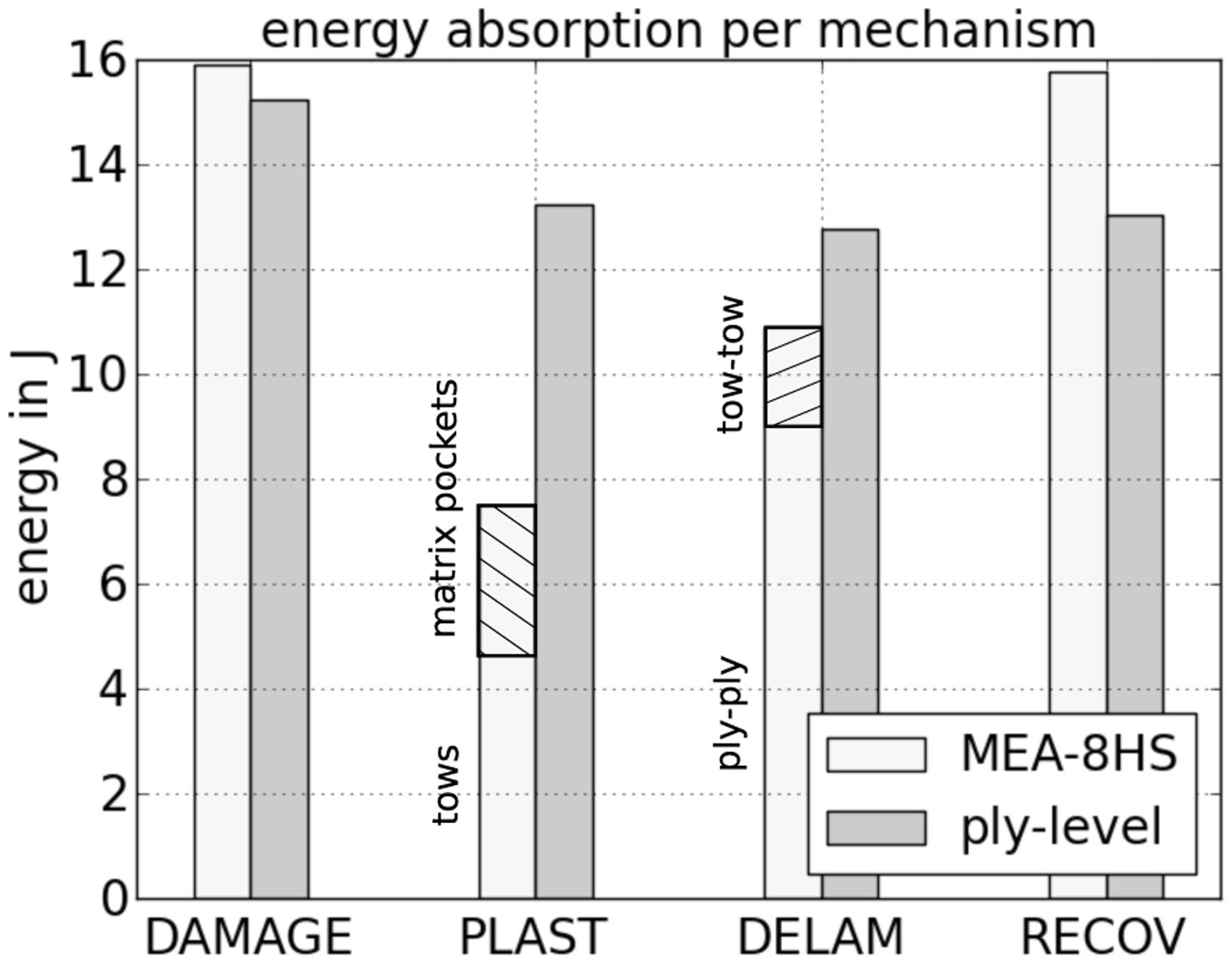
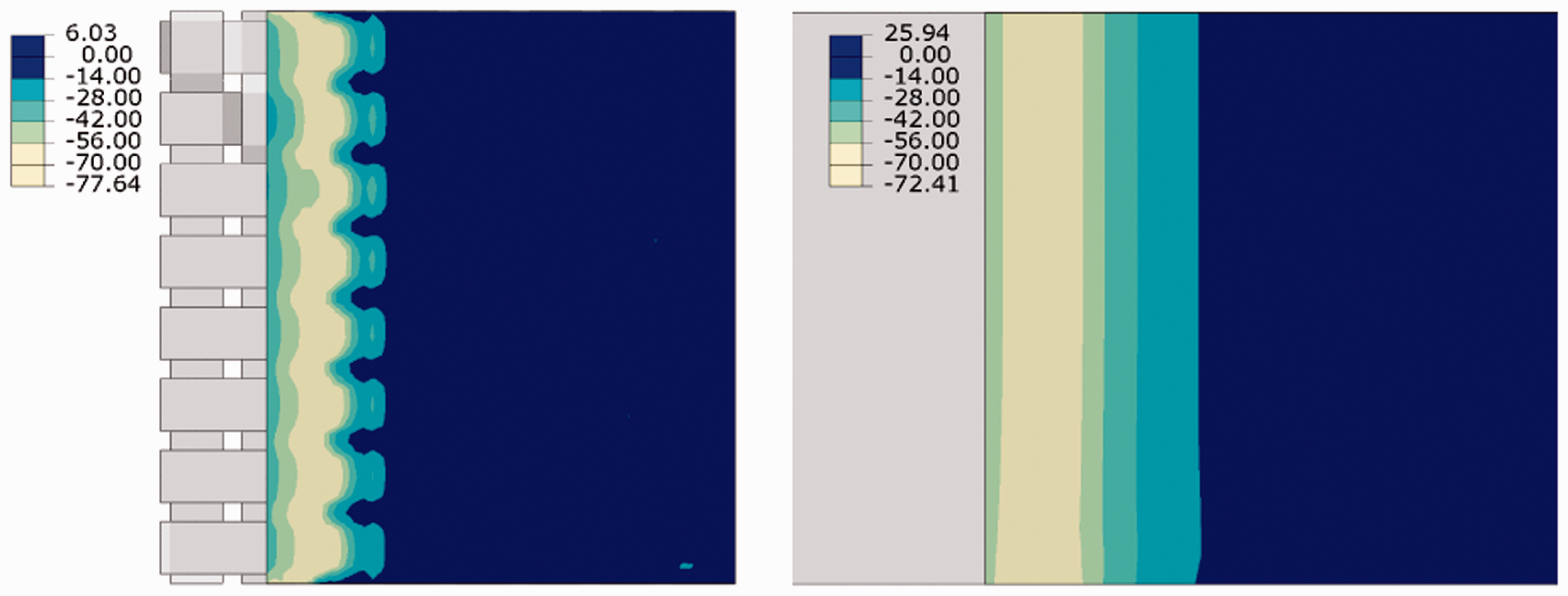
Considering the energy dissipated due to delaminations, cf. the bars “DELAM” in Figure 19, there is just a slight difference in the overall dissipated energy. However, within the tow-level model delaminations are also occurring between individual tows whereas this mechanism is not accounted for in the ply-level model. Hence, when comparing just the ply–ply delamination behaviour differences between the models become more apparent. Figure 21 shows a comparison of the delaminated area per inter-ply interface between the tow-level model (MEA-8HS) and the ply-level model. It can be seen that the ply-level model predicts larger delaminated areas in every interface. The through-thickness distribution predicted by the ply-level model follows the same trend as predicted by the tow-level model, where the differences get slightly larger towards interfaces at the backside of the laminate. One cause of these differences, obviously, is represented by the tow-level model’s capability to account for tow–tow delamination. Another reason is represented by the effect of the fabric topology, i.e. the fluctuations in the stress and strain fields within the fabric plies, on the interface tractions. Figure 22 shows a comparison of the predicted transverse shear stress component distribution within the middle interface of a laminate in a three-point bending end notched flexure test.
35
It can be seen that the distribution of the transverse shear stress component is markedly influenced depending on whether the fabric plies are modelled at the tow-level or at the ply-level. As the onset of delamination is predicted by a traction based criterion, the effect of the length scale of the geometrical discretisation of the plies on the distribution of the interface tractions obviously influences the predicted delamination behaviour.
Comparison of predicted delaminated area per inter-ply interface. Interface number seven is the one closest to the impacted surface of the laminate. Fluctuations in the field of the transverse shear stress component (in MPa) within the middle interface of a laminate in a three-point bending end notched flexure test.
35
Left: Tow-level model. Right: Ply-level model.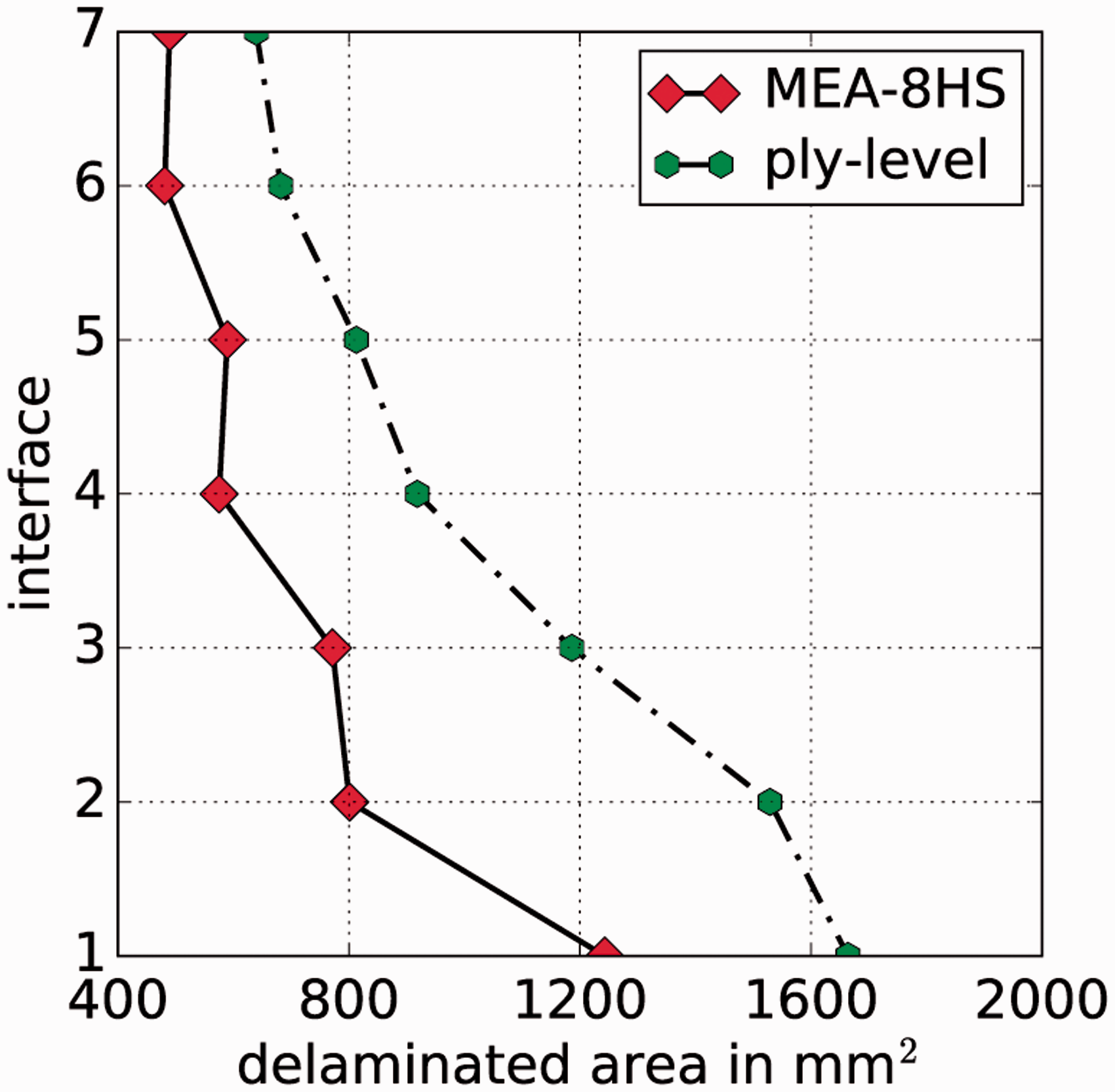
The energy absorbed due to ply damage is represented by the bars “DAMAGE” in Figure 19. Considering the tow-level model, this part of dissipated energy encompasses fibre damage and matrix damage within the tows, as well as matrix damage within the matrix pockets. In the ply-level model, these failure modes are modelled in a homogenised way, i.e. as ply damage. As can be seen, the predicted amount of energy dissipated due to ply damage is almost equal for both models indicating that there is no significant influence of the modelling length scale.
The difference in the recoverable energy, cf. the bars “RECOV” in Figure 19, originates from a different amount of predicted kinetic energy within the laminate, which is higher in the case of the tow-level model. &A reason might be that the laminate can be split up into more individual parts (e.g. individual tows may be separated from each other) in the case of the tow-level model and, thus, the damaged laminate exhibits more motion after impact.
Summary
A multiscale modelling approach for simulating impact damage within fabric reinforced composite laminates is developed. Thereby, the topology of a multi-layered fabric reinforced laminate is modelled at tow-level for a sub-domain embedded in a shell layer with a homogenised representation of the laminate. Within the tow-level domain, individual tows as well as unreinforced resin zones are entirely modelled using shell elements, which are coupled appropriately. The interfaces between adjacent plies, as well as the interfaces between tows, are modelled using CZEs. Material nonlinearities such as damage and plasticity-like behaviour of tows, inelastic behaviour of unreinforced resin zones up to fracture and delamination of plies and tows are accounted for.
As an example, a numerical simulation of a laminated plate consisting of eight carbon fabric epoxy plies with eight harness satin weaving style in a drop tower test setup is conducted using the explicit Finite Element code Abaqus/Explicit v6.14. The spatial distribution of intra- and inter-ply damage is predicted and the total amount of energy absorbed by the plate as well as the contributions of individual mechanisms are evaluated. Comparisons to results from equivalent experiments show very good agreement. Insights into the impact behaviour of fabric reinforced laminates are gained at a high level of detail, exceeding usual experimental evaluation capabilities.
The presented MEA offers the possibility to investigate the effect of the fabric topology on the impact behaviour of woven laminates, as different weaving styles can be modelled in a fully automated way. Moreover, the damage and failure behaviour of hybrid fabric plies composed of tows made from different materials can be modelled. It is found that the energy absorption behaviour of fabric reinforced laminates is hardly influenced by the degree of tow undulation. Furthermore, a detailed investigation of the effect of the length scale of the geometrical discretisation on the laminate’s predicted energy absorption is conducted by comparing simulation results of a shell element based ply-level model with those obtained using the presented tow-level modelling approach.
Footnotes
Declaration of Conflicting Interests
The author(s) declared no potential conflicts of interest with respect to the research, authorship, and/or publication of this article.
Funding
The author(s) disclosed receipt of the following financial support for the research, authorship, and/or publication of this article: the funding within the framework of the TAKE OFF program by the Austrian Research Promotion Agency (FFG) and the Austrian Federal Ministry for Transport, Innovation and Technology.