
Abstract
This paper presents the physical, mechanical, and durability characterization of glass fiber-reinforced polymer solid and tubular bars. These bars were subsequently used as rock bolts for ground control of the Jurong Rock Caverns in Singapore. The long-term performance of these bars was assessed under harsh environmental exposure (saline solution) simulating the subsea cavern water. The test parameters were (1) type of bars (solid and tubular), (2) temperature (20, 40, and 50℃), and (3) conditioning time (1000, 3000, and 5000 h). The measured tensile strengths of the bars before and after exposure were considered as a measure of the durability performance of the specimens and were used for long-term properties prediction based on a theoretical model. Moreover, microstructural analyzes using scanning electronic microscopy, Fourier transform infrared spectroscopy, and differential scanning calorimetry are also conducted to investigate the deterioration of fiber, matrix, and the fiber/matrix interface due to environmental conditioning. The results show the very high long-term durability of solid and tubular glass fiber-reinforced polymer rock bolts exposed to field conditions. The predicted tensile strength retention at a MAT of 32℃, with an RH of 100%, is 0.90 and 0.82 for a service life of 100 years for solid and tubular glass fiber-reinforced polymer bars, respectively. Based on the findings of this research, the tested glass fiber-reinforced polymer rock bolts were recommended as alternatives to stainless-steel rock bolts and successfully used as ground control in the Jurong Rock Caverns in Singapore.
Keywords
Introduction
Anchors and rock bolts are widely used in slope engineering, in supporting tunnels and large caves, and in restoring engineering structures. These devices can improve the strength and stability of ground, rock masses, and other structures. Cement-grouted bolts are among the most broadly used in civil engineering and are frequently used in temporary and permanent structure members.1,2 The main component of cement-grouted bolts is a bar, which is inserted into a hole drilled in rock and then grouted with cement paste being injected into the interstice between the rock and solid bars or through the hollow core of the tubular bars. Bars or bolts are usually made of steel, which is prone to rusting in aggressive environments and then impairs the safety and reliability of the bolted, stabilized structure. Solving this problem is a major concern among civil and geotechnical engineers. Recently, fiber-reinforced-polymer (FRP) bars have come on the market for use as anchors, tendons, and rock bolts as alternatives to conventional ground-control elements made of steel.3,4 FRP bars offer many advantages over conventional steel bars, including a density of one-quarter to one-fifth that of steel, greater tensile strength than steel, and no corrosion even in harsh chemical environments.5–7 The force driving worldwide acceptance and use of glass-fiber-reinforced polymers (GFRP) is its cost–performance ratio. Unfortunately, uncertainty remains about the long-term performance of GFRP under some special conditions, such as in mining environments. Considerable research has been conducted in the past decade to assess the suitability of GFRP bars in reinforced-concrete structures and the durability of GFRP reinforcing bars subjected to aging in alkaline solutions.8–12 Nevertheless, the data on the durability of GFRP rock bolts subjected to saline solutions simulating mining applications are very limited.
Research gap and statement of the problem
Several studies have addressed the durability of GFRP bars as internal reinforcement of concrete.8–14 Very limited studies, however, have been conducted on the durability of GFRP bars used as rock bolts and subjected to saline solutions or to simulated mining environments, which would be of crucial relevance to the Jurong Rock Caverns project. The properties of the pultruded products (void content, interface quality, and fiber distribution) and the nature of the aggressive environment can lead to important changes in the final product’s behavior and durability. Therefore, the available data on the durability of GFRP reinforcing bars subjected to typical alkaline may not be directly applicable to GFRP rock bolts subjected to saline solution and high temperature.
Research significance
In order to assess the feasibility of using GFRP bolts in the Jurong Rock Caverns in Singapore, an elaborate test program was carried out at the University of Sherbrooke in collaboration with Hyundai Engineering & Construction (Singapore) and Firep International AG (Switzerland). The test program included two types of vinyl-ester/GFRP rock bolts consisting of solid and tubular GFRP bars (with hollow-core). The purpose was to assess the environmental durability of the solid and tubular GFRP bars subjected to a saline solution simulating the subsea cavern water and predicting their long-term behavior in such environments in order to determine if they were appropriate for use in the Jurong Rock Caverns. The study simulated rather aggressive conditions by immersing the GFRP bars in a saline solution at different elevated temperatures up to for 5000 h. Tensile strength was considered the primary structural parameter and was therefore used an indicator of degradation due to exposure. Additional microstructural and physical characterizations were performed on the reference and conditioned GFRP rock bolts. Chemical degradation was also assessed with Fourier transform infrared spectroscopy (FTIR). In addition, the Arrhenius theory was used to predict the durability and service life of the new GFPR bars used as rock bolts for ground control such as in mining environments or as reinforcement for concrete structures.
Description of the Jurong Rock Caverns in Singapore
Jurong Rock Caverns (JRC), Southeast Asia’s first underground rock-cavern facility for storing liquid hydrocarbons, is located at a depth of 150 m below Jurong Island’s Banyan Basin in Singapore. The facility, located beneath the seabed, consists of five storage caverns with a storage capacity of approximately 1.5 million cubic meters, 9 km of operation tunnels, access tunnels, maintenance chambers, and water-curtain galleries built on two subterranean levels. The galleries of each cavern are 20 m wide by 27 m high by approximately 340 m long. By using subterranean storage spaces, the JRC not only ensures the safety of the stored products, but frees approximately 60 ha of land that could be used to house higher value-added activities such as petrochemical manufacturing activities. The basic engineering design consultant is the Geostock-Jurong Consultants consortium (France–Singapore joint venture). The design-and-build contractor is Hyundai Engineering and Construction (Korea), who has employed Parsons Brinckerhoff as the civil-works designer and Hyundai Engineering as the designer for mechanical, electrical, and instrumentation (MEI) works. The ambitious Jurong Rock Caverns took six years of planning and a further eight of construction at a cost of $950 million, with about 1700 workers employed. The rock caverns were officially opened on September 2014.
The caverns were built using a technique that involved drilling and blasting sedimentary rock; for greater stability, the inner walls were lined with rock bolts. Early in the design process, conventional steel rock bolts with resin polymer grout were considered. Owing to the corrosive hydrologic environment, weight and handling considerations, local construction preferences, and the requirement to have a cavern design life of 50 years, GFRP rock bolts were proposed as an alternative to stainless-steel bolts.15,16 More than 80,000 cement-grouted GFRP solid and tubular bars (similar to those tested in this study) varying in length from 3.5 to 5.5 m were used in this project (see Figure 1).
Overview of one of the Jurong Rock Caverns (the white dots in the roof are the GFRP rock bolts). GFRP: glass fiber-reinforced polymer.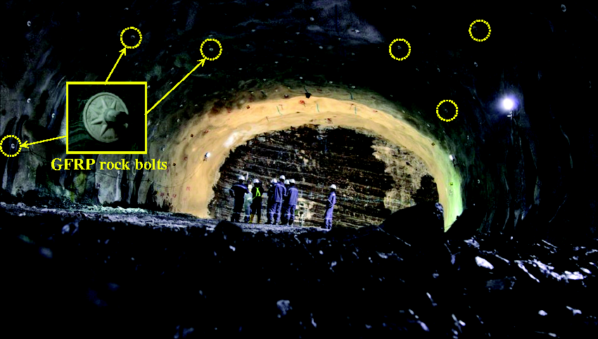
Experimental program
Materials
Solid and tubular GFRP rock bolts were examined and tested at the University of Sherbrooke and, as a result, were subsequently used as rock bolts (passive anchors) for ground control of the Jurong Rock Caverns (JRC) in Singapore. These bolts were manufactured by Firep International AG (Switzerland). A passive soil anchor is tensioned as the structure itself applies load to it. The designed load for these GFRP anchors is less than 25% of the guaranteed tensile strength (code stress limit). Past research indicated that this stress level (25%) has no significant effect on the durability and long-term prediction of GFRP bars. 17
The solid GFRP bolts had an outer diameter of 25 mm, while the tubular bolt had an outer diameter of 28 mm with an inn diameter of 12 mm. It is worth mentioning that rock bolts are named in the tunnelling industry by their outer diameter, while rebars for concrete structures are referred to by their nominal diameter. The solid and tubular GFRP bolts were designed to have the same cross-sectional area for stress calculation: 350 mm2 as the nominal area and 443 mm2 as the effective cross-sectional area (area by immersion test).
All the tensile properties reported in this paper were determined using the nominal area of 350 mm2 for the both GFRP rock bolts. Figure 2 shows a picture of the solid and tubular GFRP bolts, which have continuously profiled surfaces. Both the solid and tubular GFRP bolts were made of continuous ECR-glass fibers impregnated in a vinyl-ester resin using the pultrusion process, leading to a cure ratio of more than 99%. The mass fractions of glass were 83.0% and 82.5% for the solid and tubular bolts, respectively, and were determined by thermogravimetric analysis according to ASTM.
18
Their relative densities according to ASTM
19
were 2.11 and 2.09 for the solid and tubular bolts, respectively. All of the bars were cut into 1440 mm lengths to perform tensile testing as specified in ASTM.
20
The free GFRP bar length between the anchors was 520 mm; the inside diameter, wall thickness, and length of the steel anchors were 38.4, 4.8, and 460 mm, respectively. The GFRP bars or bolts were divided into three series: (1) the unconditioned reference samples (solid and tubular), (2) the conditioned solid rock-bolt samples (27 bars) immersed in saline solution, and (3) conditioned tubular rock-bolt samples (27 bars) filled with cement grout and immersed in saline solution. The cement grout used to fill the tubular GFRP bars consisted of Type I cement according to ASTM
21
and had a water-to-cement ratio (w/c) of 0.40.
Schematic view of GFRP rock-bolt specimens (a) tubular bar, (b) tubular bar filled with cement grout, and (c) solid bar. GFRP: glass fiber-reinforced polymer.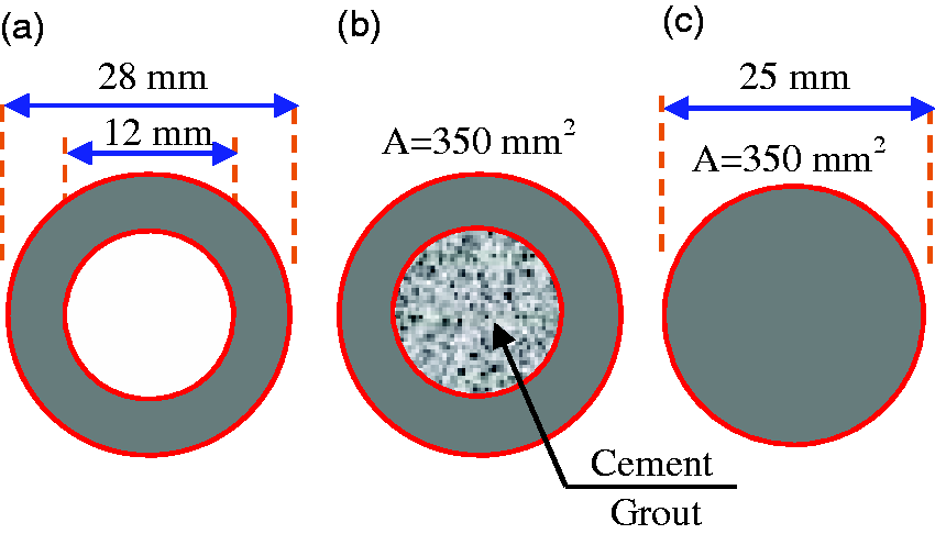
Advantages of tubular versus solid GFRP bars
New tubular GFRP bars (with a hollow core) have been recently developed and marketed. Tubular bars provide two main advantages over other bars with an equivalent cross-sectional area: (a) increased surface area, yielding higher bond-to-concrete; and (b) reduction of shear-lag effect, increasing the effective cross-sectional area of glass fibers carrying load.22,23 Figure 3 presents a schematic drawing of the phenomenon of shear lag for the solid and tubular GFRP bars. The figure indicates that, when the FRP bars experienced tensile forces, their tensile strength changed due to the development of higher stress in the outer fibers than in the inner ones due to shear lag occurring in the bar section.
24
This phenomenon can be attributed to the fact that stress developing at the fiber near the bar surface is not fully transferred to fibers located in the core, resulting in the whole section’s inefficiency. Since shear lag prevents central fibers from fully developing their proper performance, a cost-efficient section can be designed using tubular GFRP bars of equivalent cross-sectional area.
Shear lag of solid and tubular GFRP bars. GFRP: glass fiber-reinforced polymer.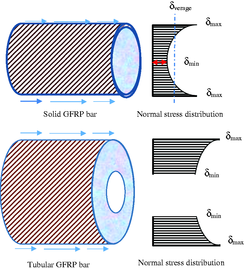
Applications of grouted tubular and solid GFRP rock bolts
For permanent applications or in rock in which corrosive groundwater is present, the space between the solid bolt and rock should be filled with cement or resin grout. The conventional method of grouting up hole solid rock bolts is to use a short grout tube to feed the grout into the hole. A smaller diameter breather tube, extending to the bottom of the hole, allows air to bleed out. The breather tube is generally taped to the bolt shank. This tends to cause problems because the tube and its fasteners can be damaged during transportation or insertion into the hole. In addition, the faceplate has to be drilled to accommodate both tubes. Sealing the system for grout injection can be a problem. Many of these difficulties can be overcome by using a hollow-core (tubular) bolt. These tubular bolts make the grouting process much more reliable and should be considered wherever permanent rock bolt installations are required. The grout should be injected through a short grout tube inserted into the hole collar, and the bolt’s central hole should be used as a breather tube. When installing these bolts in down holes, the grout should be fed through the bolt to the end of the hole, and the short tube used as a breather tube. Solid and cement-grout-tubular GFRP rock bolts were used as passive anchors for ground control in the Jurong Rock Caverns (JRC) in Singapore. In this study, the durability of these bolts was simulated and investigated.
Specimens and test program
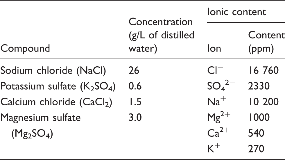
Complete composition of the saline solution used in this study.
For predicting long-term properties, three solid GFRP bolts and three cement-grout-filled tubular GFRP bolts were removed from the saline solution after every time period and tested under tension to compare their tensile-strength retention values to those of the reference specimens. The surface of the GFRP rock bolts (solid or tubular) evidenced no significant changes after specimen immersion.
Tensile tests
All of the GFRP rock bolts were tested under tension according to ASTM. 29 Each specimen was instrumented with one linear variable differential transformer (LVDT; 200 mm in length), at specimen mid-length, to capture specimen elongation during testing. The test was carried out using a Baldwin testing machine and the load was increased until failure. For each tensile test, the specimen was mounted on the press with the steel-pipe anchors held between the wedges of the machine’s upper and lower jaws. The tubular GFRP rock bolts were tested with their cement-grout core centered to avoid any damage to the specimen due to the removal of the cement grout. The average loading rate was around 300 MPa/min. The applied load and bar elongation were recorded during the test with a data-acquisition system monitored by a computer. Due to the brittle nature of GFRP, no yielding occurred and the stress–strain behavior was linear.
Life prediction approach for solid and tubular GFRP bars used as concrete reinforcement
In order to achieve more refined design of solid and tubular GFRP bars reinforced concrete under service, environmental reduction factor (CE) needs to be developed by taking all the effects of service temperature, relative humidity (RH), and design life into account. Several publications revealed that the degradation behavior of GFRP bar subjected to solutions or moisture saturated concrete would follow Arrhenius relationship.13,30 Based on the proposed model by Huang and Aboutaha,
31
the prediction of long-term behavior and service life of solid and tubular GFRP Bars were assessed at 32℃ for 50, 100, 150, and 200 years. The model incorporates the effects of temperature, design life, and RH of exposure into the environmental (CE) for the FRP bars used as concrete reinforcement. Equation (1) expresses the strength retention of GFRP bars for specific design service life and service temperature


By substituting the values of Δ2 and Δ3 into equation (1), fd can be rewritten as equation (5)

It is known that the contained water in concrete can be classified as capillary water, adsorbed water, interlayer water and chemically combined water. Huang and Aboutaha
31
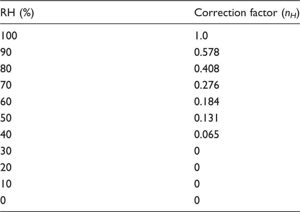
noted that the transportation of OH− can only occur in capillary water and some adsorbed water, which could be easily affected by the environmental relative humidity (RH). In moisture-saturated concrete, the degradation rate of FRP bars is the highest, and the degradation rate under less humidity can be adjusted using a correction factor (nH), which is closely related to the RH. The correction factor (nH) was assumed to be the same as the ratio of capillary and adsorbed water in the water content in concrete, as presented in Table 7. The data presented in Table 7 are adapted from Huang and Aboutaha.
31
Thus, the design tensile strength or predicted strength of solid and tubular GFRP bars in both saturated and unsaturated concretes can be written as equation (6)

Water-immersion test
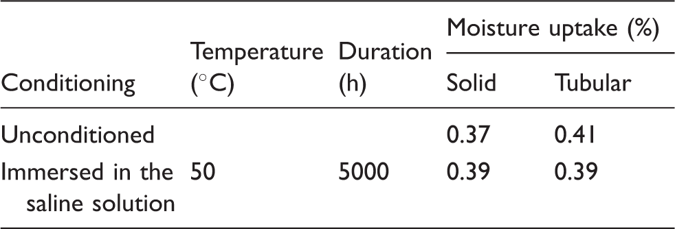
The moisture uptake at saturation of the solid and tubular GFRP rock bolts was determined before and after conditioning according to ASTM, 20 except that the immersions were performed in tap water instead of distilled water. Three 50 mm long specimens of unconditioned and conditioned GFRP bars were cut, surface dried, and weighed prior to immersion in water at 50℃ for three weeks. The samples were removed from the water at the end of three weeks, dried in an oven, and weighed.
The water content at saturation in weight percent (Ws) was calculated using equation (7)

The percentage of moisture uptake was calculated and the gain in mass was corrected to take into account possible specimen mass loss due to various dissolution phenomena during the aging procedure (such as hydrolysis) by completely drying the immersed specimens, placing them in an oven at 100℃ for 24 h, and comparing their dried masses to their initial masses.
Scanning electron microscopy
SEM observations and image analysis of the solid and tubular GFRP rock bolts were performed to observe specimen microstructure before and after aging. The samples observed under SEM were the unconditioned specimens and specimens aged for 5000 h in the saline solution at 50℃, which is harsher aging. All specimens observed under SEM were first cut, polished, and coated with a thin layer of gold–palladium with a vapor-deposition process. After the surfaces were coated, microstructural observations were performed on a JEOL JSM-840A SEM. These observations were conducted to determine any potential degradation of the polymer matrix, glass fibers, or interfaces.
Differential scanning calorimetry
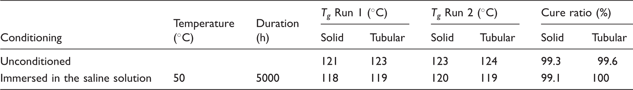
Twelve-milligram to 15 mg specimens from both unconditioned and aged samples were sealed in aluminum pans and analyzed in a TA Instruments DSC Q10 calorimeter equipped with a refrigerated cooling system. Analysis was conducted on solid and tubular GFRP rock bolts in modulated DSC mode. The specimens were heated from 25℃ to 195℃ at a rate of 5℃/min. The glass transition temperature (Tg) was determined for both specimens in accordance with ASTM E. 33 Two scans were performed for each specimen. The first scan is useful in determining the difference in Tg between the reference and conditioned specimens. A decrease in Tg for the conditioned samples would indicate a plasticizing effect or chemical degradation. The second scan gives information about the degradation mechanism. A shift to a higher Tg could be observed due to post-curing during the first scan. If the aged sample’s Tg falls within the same range as the Tg of the reference sample after the second scan, then the plasticizing effect due to the moisture absorption is reversible. If the aged sample’s Tg remains lower than that of the reference, the chemical degradation is irreversible.
FTIR
FTIR analysis of the unconditioned bolts and bolts aged in saline solution at 50℃ for 5000 h was conducted. This analysis was performed to determine if hydrolysis reactions occurred in the polymer resin, which can lead to an important loss of mechanical properties. Measurements were taken on the external surface and in the bulk material of both the solid and tubular bolts. In addition, measurements were also taken on the internal surface of the tubular bolts to determine the effect of saturated cement grout. FTIR spectra were recorded using a Nicolet Magna-550 spectrometer equipped with an attenuated total reflectance (ATR) device. Fifty scans were routinely acquired with an optical retardation of 0.25 cm to yield a resolution of 4 cm−1.
Test results, analysis and discussion
Mechanical properties
The tensile testing of the reference specimens showed an approximately linear behavior up to failure. All of the specimens failed suddenly, as expected, as the result of fiber rupture. Figure 4 shows the failure mode of representative specimens for each GFRP bar type. All the failures started with splitting and ended with bar rupture. The splitting was accompanied by the delamination of fibers and resin, as shown in Figure 4. The failure initiated at the quarter point of the gauge length and extended to the other side by delamination. This might also be related to the bar’s surface type (continuously profiled surface). A similar mode of failure was observed for the specimens immersed in the saline solution, as shown in Figure 4. Micelli and Nanni
34
also observed similar tensile-failure modes of GFRP bars. It is also worth mentioning that no chemical deposits were observed on the surface of the conditioned GFRP bars before tensile testing for residual properties.
Typical failure mode of tested specimens subjected to tensile testing. (a) Reference solid bolts; (b) Reference tubular bolts; (c) Solid bolts conditioned for 1000 h at 50℃; and (d) Tubular bolts conditioned for 1000 h at 50℃.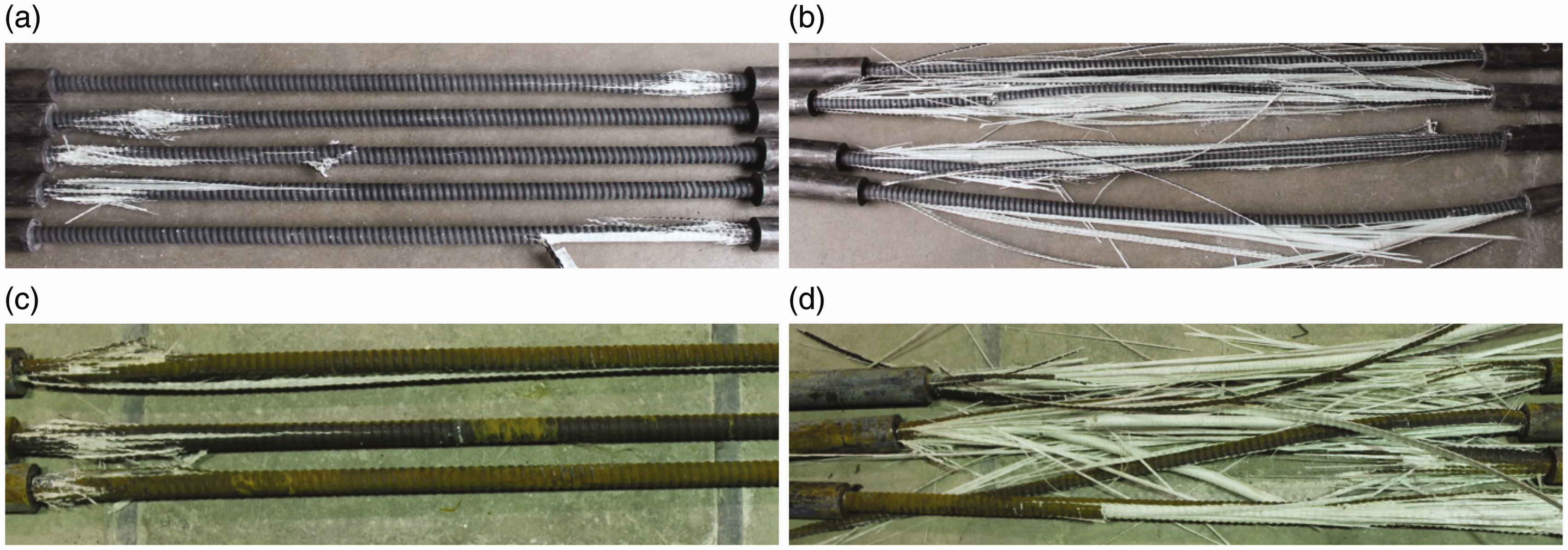
Average tensile properties of GFRP reference and conditioned specimens at 23℃.
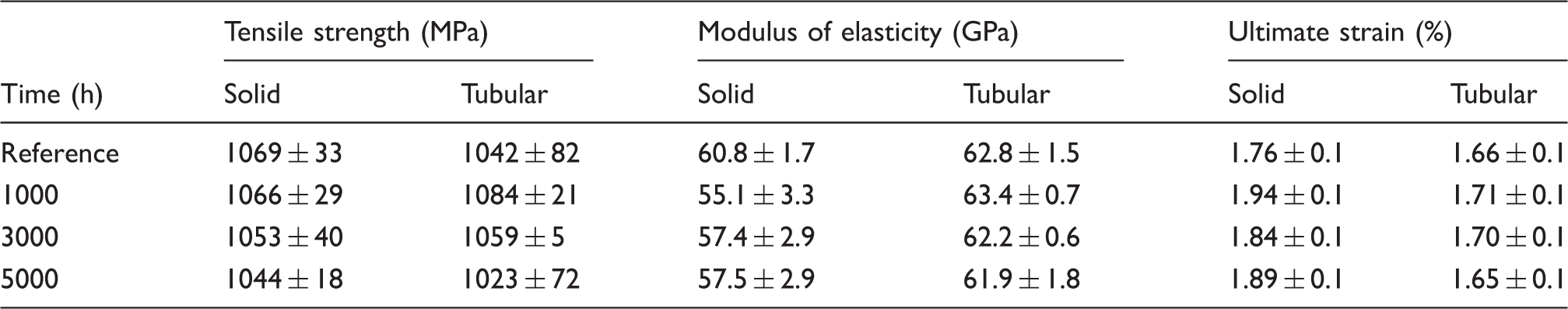
GFRP: glass fiber-reinforced polymer.
Average tensile properties of GFRP conditioned specimens at 40℃.
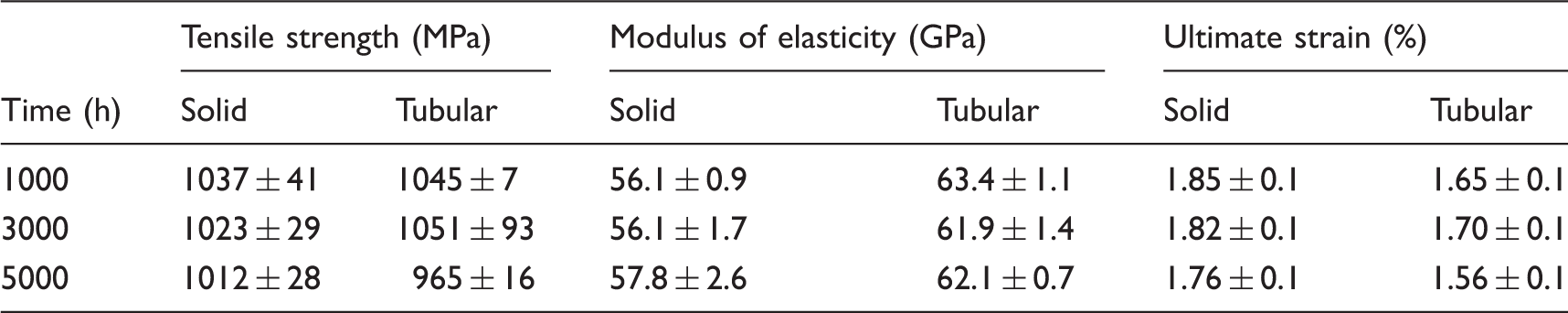
GFRP: glass fiber-reinforced polymer.
Average tensile properties of GFRP conditioned specimens at 50℃.
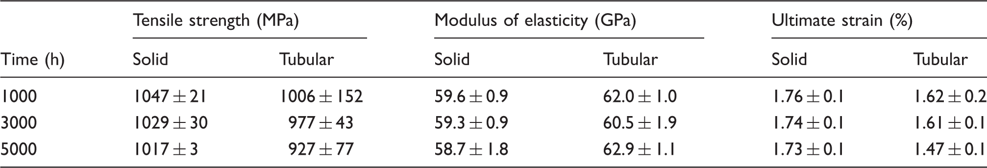
GFRP: glass fiber-reinforced polymer.
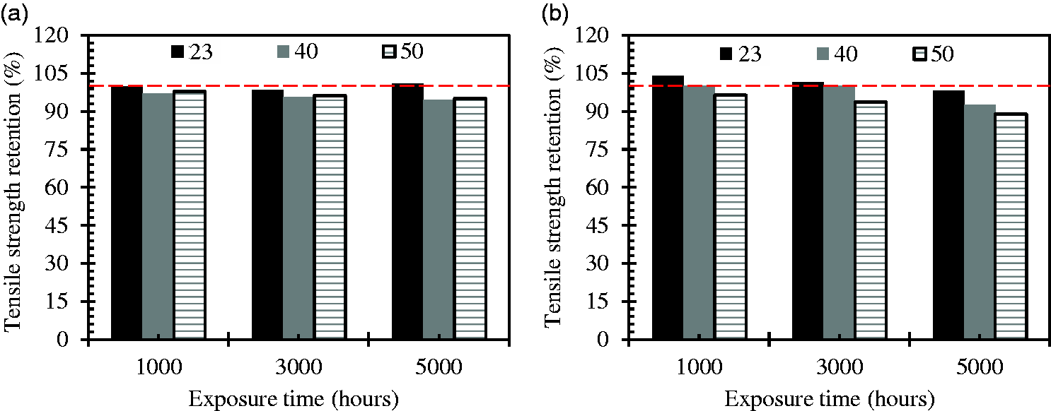
Tensile-strength retention of conditioned GFRP rock bolts aged in saline solution at 23℃, 40℃, and 50℃ for (a) solid bolts and (b) tubular bolts. GFRP: glass fiber-reinforced polymer.
Figure 5 shows that no significant decrease of the ultimate tensile strength of solid and tubular bars occurred with increased immersion duration or temperature. It can be seen that, for an immersion duration of 5000 h at 50℃, the strength loss was 2% and 3% for the solid and tubular GFRP bars, respectively. The slight variation in tensile strength is probably related to the slight increase in moisture absorption over time, leading to plasticizing effects of the polymer matrix. 35 Moreover, the test results in this study indicate that the degradation rate stabilized and decreased quickly as the exposure time increased from 3000 to 5000 h. The same behavior was also found in the literature as the exposure time increased from 3000 and 7000 h. It was stated that there was an indication of delayed increase in degradation rates for 210–270 data.26,32
Effect on Young’s modulus
Figure 6 shows the change in the elastic modulus of the aged bars with immersion time at various temperatures. Indeed, it can be seen from the measured results that, after 5000 h, the loss of elastic modulus was negligible; none of the aged solid and tubular GFRP bars were affected by the higher temperature or exposure to the saline solution. This result shows that the modulus of elasticity of the bars was not affected by aging in the simulated mining environment herein. This result can be explained by the fact that the Young’s modulus of unidirectional GFRP materials relates more to fiber properties, which are not affected by the saline solution.36,37 The slight increase in tensile modulus after 5000 h of immersion is due to variability in the test measurements.
Elastic moduli of reference and conditioned GFRP rock bolts aged in saline solution at 23℃, 40℃, and 50℃ for (a) solid bolts and (b) tubular bolts. GFRP: glass fiber-reinforced polymer.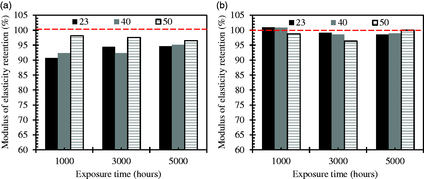
Results of water-immersion testing
Water absorption at saturation before and after conditioning in the solution.
Microstructural effects
The visual and microstructural observations showed no significant damage after 5000 h of immersion in the saline solution simulating the subsea cavern water at the highest temperature (50℃). The micrographs in Figures 7 and 8 show the fiber–matrix interface of the solid and tubular GFRP bars, respectively, for the unconditioned bolts and for the bars aged in the saline solution for 5000 h at 50℃.
Micrograph (×4000) of solid GFRP rock bolts for (a) unconditioned bolt and (b) aged in saline solution at 50℃ for 5000 h. GFRP: glass fiber-reinforced polymer. Micrograph (×4000) of tubular GFRP rock bolts for (a) unconditioned bolt and (b) aged in saline solution at 50℃ for 5000 h. GFRP: glass fiber-reinforced polymer.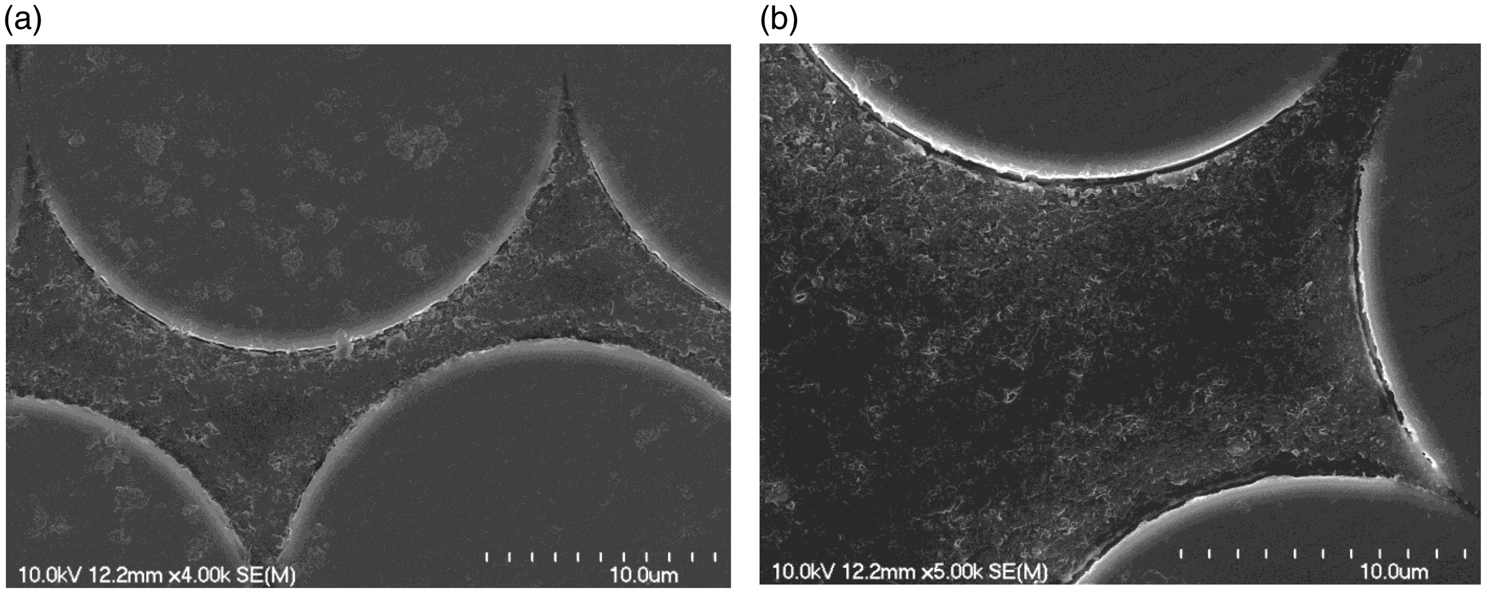
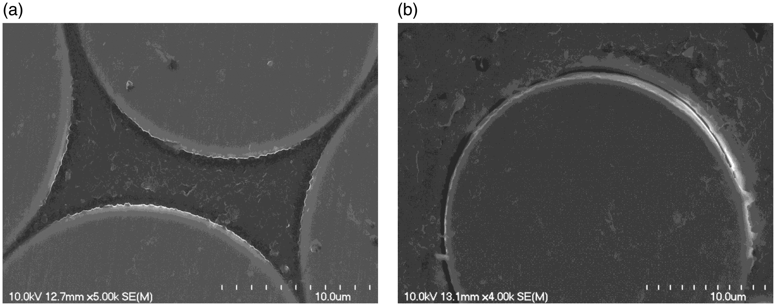
Observation of these interfaces and microstructure, in general, demonstrates that the conditioning of the solid and tubular GFRP rock bolts in the saline solution simulating the subsea cavern water slightly affected the microstructural properties of the GFRP bars and that the presence of saturated cement grout in the tubular bolts did not significantly affect bar macroscopic properties. This is in agreement with what Robert and Benmokrane 36 reported when similar cement-mortar-wrapped GFRP bars used for internal reinforcement of concrete were immersed in salt water (3% NaCl). This phenomenon clearly illustrates the fact that the tested GFRP rock bolts were not significantly affected by accelerated aging.
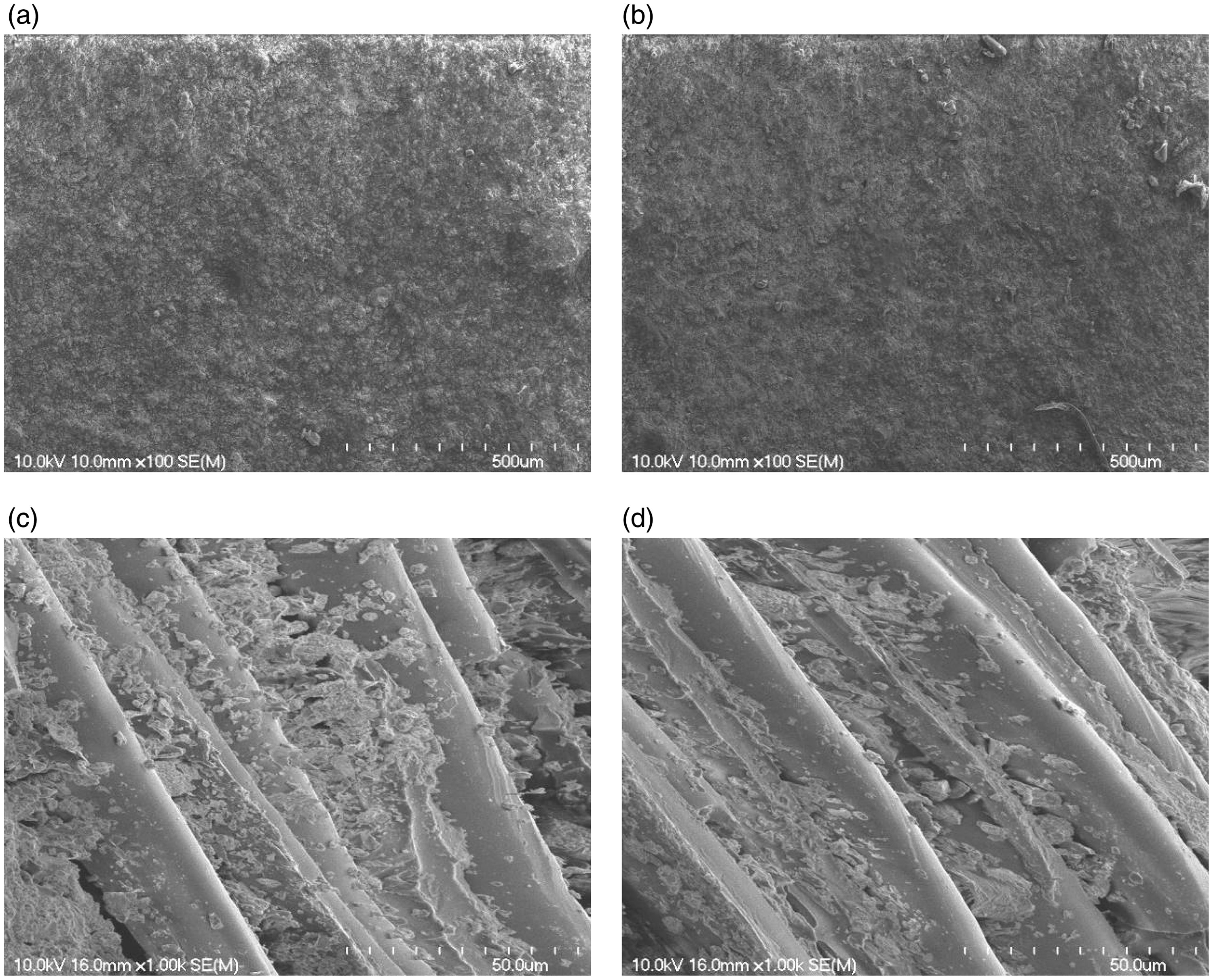
Micrographs of external and internal surfaces of the GFRP rock bolts
Figure 9 provides micrographs of external surfaces of the reference and conditioned solid GFRP rock-bolt specimens. The micrographs in Figure 10 show the external and internal surfaces of the tubular GFRP bars for unconditioned bolts and for bolts aged in the saline solution for 5000 h at 50℃. Comparing these micrographs shows no significant damage to the external surfaces of the aged solid and tubular GFRP bars (Figures 9(b) and 10(b)). Similarly, the micrograph of the internal surface of the tubular bar (Figure 10(d)) shows that the aging in the saline solution at 50℃ for 5000 h did not lead to any significant damage.
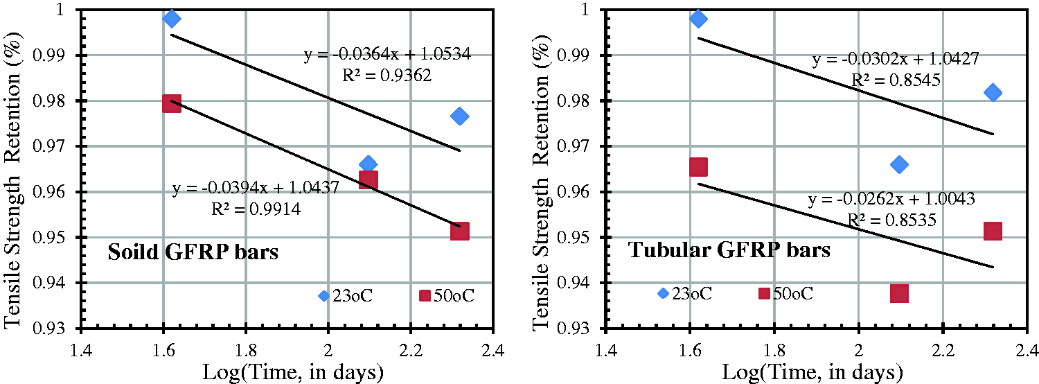
Micrographs of external surfaces of solid GFRP rock bolt specimens for (a) unconditioned reference bolt and (b) bolt aged in saline solution at 50℃ for 5000 h. GFRP: glass fiber-reinforced polymer. Micrographs of surfaces of tubular GFRP rock bolt specimens for (a) external surface of unconditioned reference bolt, (b) external surface of bolt aged in saline solution at 50℃ for 5000 h, (c) internal surface of unconditioned reference bolt, and (d) internal surface of bolt aged in saline solution at 50℃ for 5000 h. GFRP: glass fiber-reinforced polymer. Strength retention versus log(time) for solid and tubular GFRP Bars after being aged in saline solution at 23 and 50℃. GFRP: glass fiber-reinforced polymer.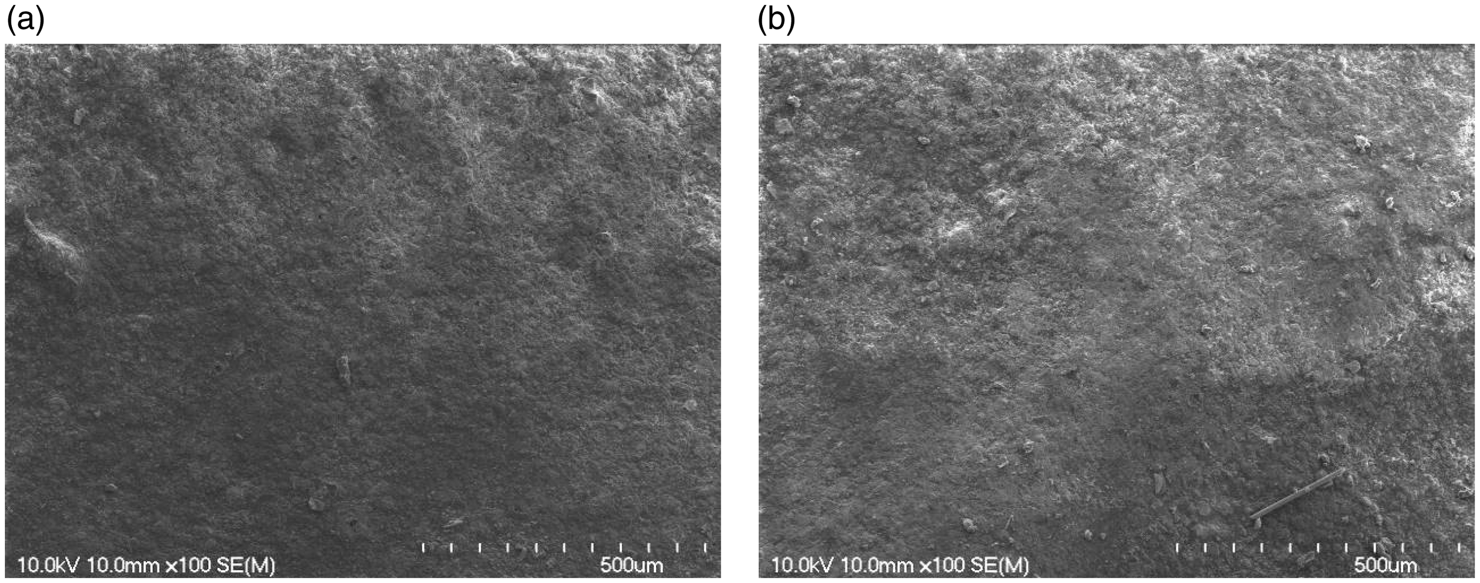
Effects on the matrix
FTIR observation of the unconditioned and GFRP rock bolts aged in the saline solution at 50℃ for 5000 h was conducted. The experimental ratio of the OH peak to the carbon–hydrogen stretching peak of the resin on the external surface of the solid GFRP bolts immersed in the saline solution for 5000 h at 50℃ was 0.25, compared to 0.21 for the unconditioned rock bolts. While, the experimental ratios of the OH peak to the carbon–hydrogen stretching peak of the external and internal surfaces of the tubular rock bolts immersed in the saline solution for 5000 h at 50℃ were 0.44 and 0.54, respectively, compared to 0.49 for the unconditioned rock bolts. So, the hydroxyl peaks did not show any significant changes. This indicates that the hydrolysis did not significantly occur under these environmental conditions.
Results of differential-scanning-calorimetry (DSC) analysis.
Relationship between the correction factor and the relative humidity (adapted from Huang and Aboutaha 31 ).
Service-life-prediction
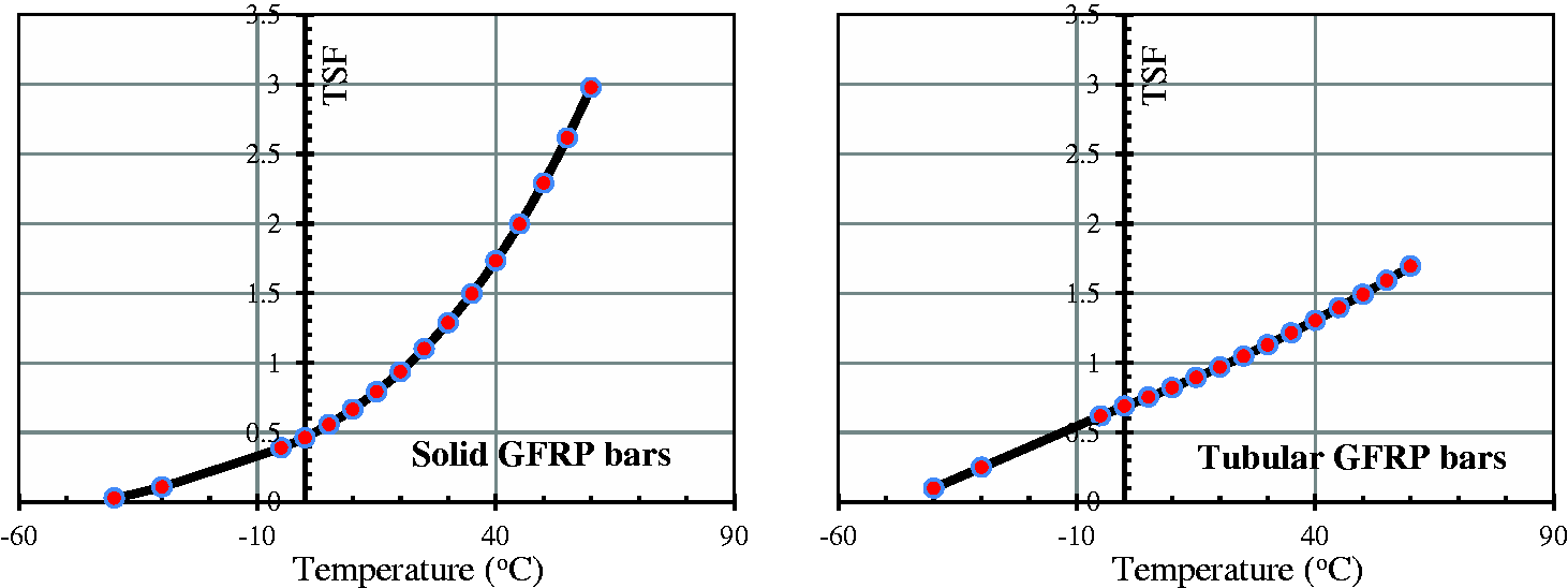
The property tensile retention value for solid and tubular GFRP specimens tested at each temperature (23 and 50℃) and conditioning time (1000, 3000, and 5000 h) were calculated as the average property value at the time of testing (t) divided by the average property value for the reference specimen (t = 0). These values were then plotted on a graph with time on the x-axis using a logarithmic scale (log-time), and the property retention value on the y-axis using a linear scale (Figure 11). Using linear regression, a line was fit through each data set (one for each conditioning temperature). The figure indicated that the slopes (φ) of the two regression lines are nearly the same, which is approximately equal to 0.0364 and 0.074 for solid and tubular GFRP bars, respectively. The regression line must have a minimum r2 of 0.80. In our case, the property tensile retention values used for the linear regression were chosen in the standard-deviation range to accommodate r2 and all the r2 values for regression lines at 23℃ and 50℃ were greater than 0.80. Meanwhile, by substituting log[5000 h (208 days)] as the value of x in the equation of regression lines, Δ1 for T1 (23℃) can be obtained as a value equal to 0.031 and 0.02733 for solid and tubular GFRP bars, respectively. The TSF value at each of the conditioning temperatures (50℃ and 23℃) was obtained as of approximately 3.1 and 1.74 for solid and tubular bars, respectively. Then by substituting the value (3.1 and 1.74) into equation (8) as the TSF value, the constant B can be obtained as a value of 2842 and 1373 for solid and tubular bars, respectively. Thus, the TSF value between the reference temperature (23℃) and other selected temperature T can be obtained using equation (8). Figure 12 shows the TSF values versus temperatures for solid and tubular GFRP bars.
TSF versus temperature.
By substituting DL = 50, 100, 150, and 200 years, values of TSF from Figure 12 and values of nH from Table 7 into equation (6), the environmental reduction factor (CE) can be obtained, as shown in Figure 13, which presents the retention factor/reduction factor for tensile strength of solid and tubular GFRP for mean annual temperature (MAT = 32℃) in Singapore and RH with 50, 100, 150, 200 years of design life.
Strength retention factor under a mean annual temperature (MAT = 32℃) in Singapore and RH for 50, 100, 150, 200 years of design life.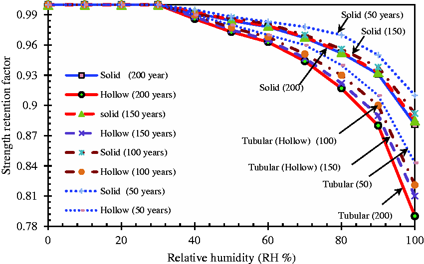
Figure 13 indicated that the predicted time to reach the determined tensile-strength retention for the solid and tubular GFRP rock bolts aged in the saline solution simulating the subsea cavern water (with an RH of 100%) at an isotherm temperature of 32℃ is approximately 150 years for retention factor of more than 89% and 80%, respectively. Moreover, the predicted service life of the solid and tubular GFRP rock bolts aged in the saline solution, at an isotherm temperature of 32℃ and with an RH of 100%, is 0.88 and 0.78 for 200 years. For cases where RH < 90%, the values of the retention or reduction factor, for the solid and tubular bars, can retain over 0.93 of its original tensile strength after 200 years service in concrete environment. While, these values were ranged between 92% and 95% for the RH = 80%. As long as RH is under 80%, the RFs are greater than 90% (ACI 38 ). These predictions show that the solid and tubular GFRP rock bolts tested in this study are durable with respect to the saline environment encountered in mining applications, since the saline solution used herein closely simulates the subsea cavern water. As a result, they could be adopted for the Jurong Rock Caverns project.
Summary and conclusions
In this research study, to assess the durability performance of the GFRP rock bolts, the GFRP bolts were subjected to a saline solution simulating subsea cavern water at 23℃, 40℃, and 50℃ for 1000; 3000; and 5000 h of conditioning. In addition, FTIR, differential scanning calorimetry (DSC), and scanning electron microscopy (SEM) were used to characterize the aging effect on the GFRP rock bolts. Based on the results of this study, the following conclusions may be drawn about the tested products:
The change in tensile strength of the tested GFRP bolts was minor even at high temperatures (50℃), making for a more aggressive environment (highly concentrated saline solution). No significant microstructural changes were observed after 5000 h of immersion of the GFRP bolts in the saline solution at 50℃. The interfaces between the resin and fibers appeared unaffected by moisture absorption and high temperature. Also, the polymer matrix was not affected by moisture absorption or high temperature: no changes in the glass transition temperature occurred, as observed by DSC. Based on the predication model, the tensile strength retention of solid and tubular GFRP rock bolts immersed in the saline solution (with an RH of 100%) at an isotherm temperature of 32℃ is approximately 150 years for retention factor of more than 89% and 80%, respectively. While, for 200 years of design life, the tensile strength retention of the solid and tubular bars, at an isotherm temperature of 32℃ and with an RH of 100%, is 0.88 and 0.78, respectively. Civil engineers currently aim at designing structures with service lives of up to 100 years. According to the predictions, even after a service life of 100 years, the tensile-strength retention of the tested GFRP rock bolts would still be greater than 82% for a mean annual temperature of 32℃ (representative of Singapore), which is higher than the design tensile strength according to ACI
38
(guaranteed tensile strength multiplied by the environmental reduction factor = CE × ffu*). Finally, the findings of this study on cement-grouted tubular and solid GFRP bars led to their adoption and successful use as rock bolts for ground stabilization of the Jurong Rock Caverns in Singapore. The GFRP bolting system has proven to be very successful, with no ground failures experienced where systematic GFRP bolting has been applied. This research and its subsequent application for the Jurong Rock Caverns project in Singapore opens the door to major applications of GFRP bars as bolts in tunnel and mining engineering around the world. Moreover, the results obtained in this investigation can be used and extended for the durability of the GFRP bars with hollow-core as reinforcing bars for concrete structures.
Footnotes
Acknowledgments
The authors would like to thank the technical staff at the Department of Civil Engineering, University of Sherbrooke (Sherbrooke, Quebec, Canada) for their assistance in fabricating and testing the specimens.
Declaration of Conflicting Interests
The author(s) declared no potential conflicts of interest with respect to the research, authorship, and/or publication of this article.
Funding
The author(s) disclosed receipt of the following financial support for the research, authorship, and/or publication of this article: The authors wish to acknowledge the financial support of Fonds de la recherche du Quebec en nature et technologies (FRQ-NT), the Natural Sciences and Engineering Research Council of Canada (NSERC), the NSERC Research Chair in Innovative FRP Reinforcement for Concrete Structures, Hyundai Engineering & Construction (Singapore), and Firep International AG (Switzerland).