






Abstract
Additive manufacturing processes have a demonstrated capacity for flexible production of metal and polymer components. More recently, capabilities for three dimensional printing of continuous fiber reinforced composites were developed. As with printed metal and polymer materials, printed composites will exhibit a unique microstructure with morphological features and process artifacts that manifest on multiple length scales. The aim of this research was to investigate the microstructures of various printed continuous fiber composites and determine linkages to consequent mechanical properties such as stiffness and strength. Samples investigated in this study comprised unidirectional carbon fibers in nylon matrix, unidirectional Kevlar fibers in nylon matrix, and Kevlar fibers in nylon matrix aligned at ±45° directions. Tensile properties of the samples were evaluated along with comparison to expected properties. Fiber volume ratios were analyzed by thermogravimetric analysis. Scanning electron microscopy and optical microscopy were used to observe and characterize the hierarchical microstructure. Both strength and stiffness were approximately 30–40% weaker than traditionally produced composites, owing to features such as imperfect interfaces between printed layers, microvoids, incomplete fill density, and similar process artefacts. Future work will investigate mitigation of such effects through process modifications and post-processing to produce higher performance printed composites.
Introduction
Three dimensional (3D) printing is an additive manufacturing method for rapid prototyping of complex geometries with metals, polymers, and more recently with fiber reinforced composite materials. The method has seen increased popularity due to its adaptable manufacturing of intricate geometries, reduction in material waste, potential for use in small fieldable fabrication units, ability to fabricate changed designs without retooling, and often relatively low fabrication costs.1–3 Fused deposition printing of thermoplastic polymer materials including Acrylonitrile Butadiene Styrene (ABS), Polylactic Acid (PLA), and Polyethylene Terephthalate Glycol (PETG)4–9 are commonly employed, and the properties of the printed materials are well documented in literature. Low mechanical strength of unreinforced thermoplastic polymers (on a weight or area basis) is the main issue limiting their range of application.
To enhance the mechanical properties of printed polymers, the process of reinforcing the matrix with high-strength fibers has been recently introduced.10–23 Continuous reinforcement provides distinct advantages in mechanical properties compared to particulate or chopped fiber reinforcement; Van Der Klift et al. and Melenka et al. conducted research where they investigated the mechanical properties of 3D-printed fiber reinforced composites, using continuous carbon or Kevlar fibers. In their research, Melenka et al. calculated the theoretical volume ratio of Kevlar fibers aligned in ±45° within a nylon matrix and developed a model to predict elastic moduli of these composites. 24 Van Der Klift et al. worked on carbon fiber reinforced nylon matrix composites and investigated the influence of various process parameters on the consequent tensile properties. They specified an optimum raster angle, infill speed, nozzle temperature, and layer thickness.
Although these studies revealed significant information regarding the mechanical properties of 3D-printed polymers and composites, much remains to be determined in understanding the unique microstructures of printed continuous fiber reinforced materials and how these microstructures affect the mechanical properties. Printed materials exhibit features on multiple length scales that must be understood to further develop the 3D printing technology and additive manufacturing. This study uses scanning electron microscopy (SEM) and optical microscopy to identify microstructural features on different length scales, such as the extra interfaces between printed layers, resin voids, gaps in print architecture, and fiber-matrix interface, in the context of how these features differ from those of traditionally manufactured polymers and composites. Comparisons of mechanical properties such as stiffness and strength are shown to illustrate the net effects of these differences in microstructural features.
Material and methods
Specimen fabrication
Two main sets of materials were fabricated in this study; continuous fiber reinforced composites and unreinforced polymer specimens as controls. Composite specimens were carbon fiber reinforced nylon, Kevlar fiber reinforced nylon (fibers are oriented along the printing direction) and Kevlar fiber reinforced nylon composites (fibers are oriented at ±45° relative to printing direction). We could fabricate Kevlar fibers in two different orientation (0° and ±45° relative to printing direction) to investigate the effect of fiber orientation. However, carbon fiber specimens were only printed in unidirectional (0° relative to printing direction) settings since the flexibility of the carbon fiber was not amenable to a cross-hatch print. As control samples, we printed nylon and PLA polymers. Fiber reinforced composite specimens and Nylon samples were fabricated with a Mark One model 3D printer. Each specimen comprised of 10 layers; had a layer height of 0.1 mm, fill pattern of triangular geometry, fill density of 100%. Apart from these specimens, PLA samples with 100% fill density were printed using an Ultimaker2™ 3D printer. Each set consisted of 5 samples.
Tensile testing
Dogbone shaped specimens were prepared for the tensile testing process. All samples had a thickness of 2.41 mm. The first sample in gray from the left in Figure 1 is the printed PLA specimen. Second and third samples represent composites reinforced with Kevlar fibers at ±45° and uniaxial directions, whereas fourth and fifth samples represent carbon reinforced nylon composite and bare, unreinforced nylon specimen, respectively.
3D-printed samples used in the research. Left to right: PLA sample produced using Ultimaker 2 printer, ±45° Kevlar fiber, unidirectional Kevlar fiber, unidirectional carbon fiber, unreinforced nylon matrix.
Specimens were tested using an Instron™ 5966 universal testing frame. Nylon samples with no fiber reinforcement were tested according to standard test method for tensile properties of plastics—ASTM D638, at 50 mm/min constant crosshead speed; whereas reinforced specimens were tested in accordance with standard test method for tensile properties of polymer matrix composite materials—ASTM D3039, at a constant crosshead speed of 2 mm/min. All strain measurements were performed with an axial clip-on extensometer. Thickness, gage length and width were measured by recording the average of three measurements from distinct points, using iGaging Absolute Origin Cal 6″/150 mm Digital Calipers. Tensile testing data was acquired using the Bluehill 3™ software. Dogbone shaped PLA samples were tested in accordance to ASTM D3039 at a constant crosshead speed of 2 mm/min.
To provide a basis of comparison between polymers fabricated via printing and traditional methods, nylon and PLA filament samples from the material supply coil of the printer were used for tensile testing. Custom epoxy holders were attached at the ends of each filament specimen to provide adequate gripping while avoiding failure in the grip area, rather than the gauge area. The epoxy grips were produced by pouring a mixture of 22% Epikure™ curing agent and 78% of Epon™ 826 resin by mass into grip molds through which the filament is positioned. The initial epoxy mixture was kept in room temperature for 24 h before it was heat-treated in an oven atmosphere of 100℃ for 1 h. Tensile tests of filaments were also performed in accordance with ASTM D3039, at a constant crosshead speed of 2 mm/min.
Density and fiber volume ratio measurements
All printed samples were subjected to density measurement using Archimedes’ principle. Samples were immersed in the experimental tube of which water level was known beforehand so as to determine the volume thereof. Subsequently, densities were obtained after the mass of each specimen was measured using the analytical balance tool.
Acid digestion, resin burnout, or other alternate methods can be labor intensive and also problematic for determination of fiber volume ratio for some material systems whereas thermogravimetric analysis (TGA) approaches can be automated and provide less subjective results. 25 Therefore, determination of fiber volume ratio was performed by TGA to provide a more robust measurement given the microstructural artifacts and non-uniform cross-section of the printed samples. In order to reduce adverse effects of moisture absorption of the polymer matrix on the TGA measurements, specimens were kept in an oven at 100℃ for 3 days to remove the moisture absorbed by the nylon matrix. The equipment used in the TGA experiments is TA Q600 SDT, which is capable of heating up to temperatures as high as 1500℃.
Microscopy of fractured specimens
SEM inspection of the specimens fractured at tensile tests as well as the specimens which are not tensile tested were used extensively to investigate and qualitatively characterize the microstructure of the printed composites on multiple relevant length scales. In some cases, magnifications which could be achieved through optical microscopy were used, but the superior depth of field in the SEM technique was required for effective visualization. In order to acquire clear images of the fractured surfaces, specimens were sputter coated with a thin (∼10 nm) layer of gold. The SEM equipment utilized in the process is FEI XL-30 Field Emission ESEM/SEM.
Results
Tensile testing of unreinforced polymers
Tensile test results of the unreinforced and printed nylon along with printed and filament PLA specimens are provided in terms of stress versus strain curves in Figure 2. Yield stress for each specimen has been determined by locating the corresponding stress values intersecting the 0.2% offset deformation line. Additionally, the results of these tests are summarized Table 1.
Stress–strain curves of the 3D-printed and traditionally fabricated polymers. (a) Nylon specimens and (b) PLA specimens. Mechanical properties of 3D-printed and traditionally produced polymer samples.

Tensile test results denote that 3D-printed polymers are weaker than the traditionally fabricated ones. This difference is more significant in 3D-printed nylon where the ultimate strength is only half of the traditionally fabricated nylon. Reduction of ultimate tensile strength is nearly 6% in PLA. Initial stiffness of the printed and traditional polymers was similar. However, the onset of stiffness loss was more pronounced in the printed polymers. Unlike ultimate stress, maximum tensile strain values were found to be independent of fabrication technique. Both printed and commercial polymers exhibited similar strains at failure.
Fiber volume ratio in 3D-printed composite specimens
Fiber volume ratios obtained via TGA.

Tensile testing of fiber reinforced composites
Tensile test results of the composite and nylon specimens are provided in terms of stress vs. strain curves in Figure 3. The resultant curves are merged in one graph to facilitate comparison of matrix and fiber types, along with their orientation. All specimens exhibited linear-elastic behavior in uniaxial tension. Failure occurred within 1.4%–2.5% strain for all tested composite samples.
Stress–strain curves of the 3D-printed composites.
Tensile properties of the reinforced specimens.

Properties used for the rule of mixtures.

In order to obtain an estimate of the theoretical axial elastic modulus of the unidirectional composites, the rule of mixtures was utilized. Measured fiber volume fractions and the elastic moduli for the constituents documented in literature10,12 were plugged in the rule of mixtures equation given below. In the results section, the results and pre-known moduli that were plugged into equation (1) were as stated in Table 4.
Comparison between rule of mixtures and experimental stress–strain variation on (a) 3D-printed carbon fiber composites and (b) 3D-printed unidirectional Kevlar fiber composites.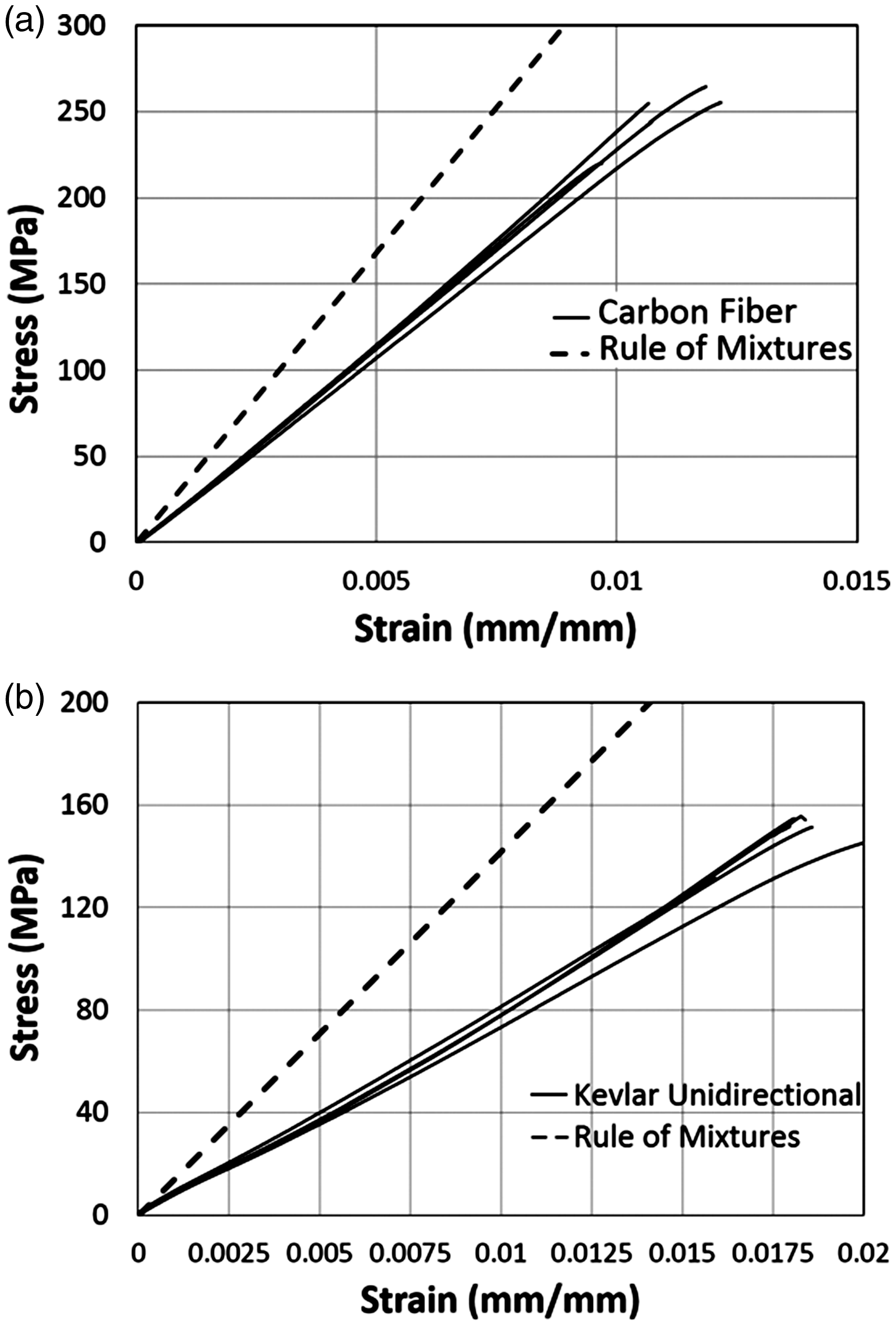
Theoretical mechanical properties for off-axis specimens can be computed through lamination theory, which is used to identify the behavior of oriented and/or layered composites. Classical lamination theory comprises the simplification of engineering assumptions such that each layer is thin and made of macroscopically homogeneous, orthotropic, linear-elastic material.28,29 Thus, this theorem was implemented on ±45° Kevlar fiber specimens, with material properties provided by Melenka et al.
24
to compute the stiffness. Figure 5 compares and contrasts the mechanical behavior of printed 45° Kevlar with this theoretically approximated stiffness (solid and dashed lines respectively). This provides another theoretical benchmark similar in such use to the rule of mixtures but more appropriate to the angled-fiber geometry of these specimens. As per the results given in Figure 5, 3D-printed 45° Kevlar fiber specimens have 40% lower elastic moduli compared to properties often achievable in traditionally produced composites.
Comparison between extensional stiffness matrix and experimental stress–strain variation on 3D-printed ±45° Kevlar fiber composites.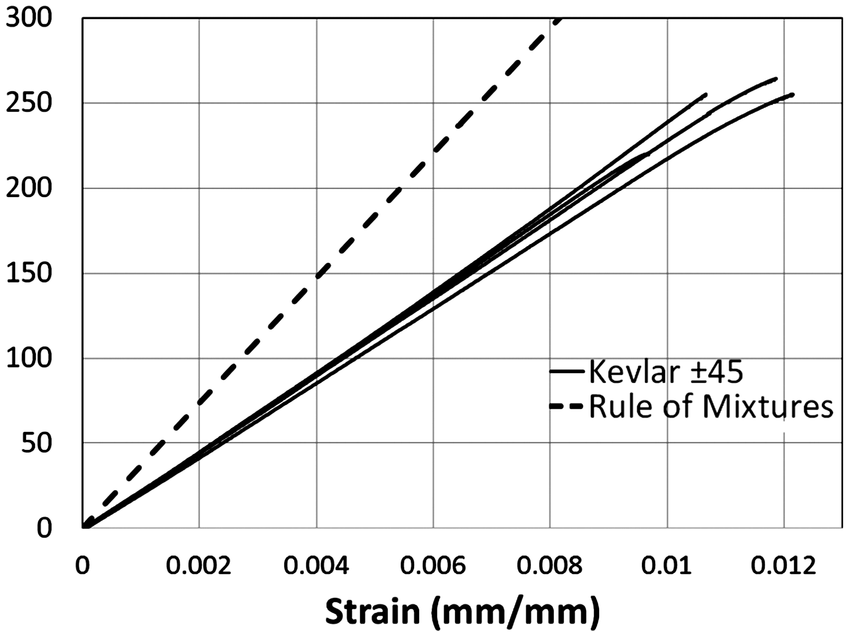
The elastic moduli measured from the tensile tests were lower than the moduli from the rule of mixtures estimates. The weaker mechanical properties compared to the traditionally produced materials were likely due to the observed matrix voids, incomplete print fill gaps, poor interface, and/or features such as polymer printline interfaces, as depicted in the SEM micrography.
Imaging of microstructure
Figure 6 represents SEM and optical microscope images of the bare PLA and nylon specimens. These images showed a substantial amount of defects and porosity in the microstructure which was a large contributing factor behind the reduction in mechanical stiffness and strength. Figure 6(a) shows a printed crosshatch pattern as the printer nozzle printed lines of the thermoplastic material to fill the requested shape and volume. This picture is taken along the longitudinal axis of a print pattern that quickly prints lines in a ±45° crosshatch pattern. The imperfect fusion of layers which drape over the previous print line are readily apparent. Rectangular gaps shown in Figure 6(b) for the same specimen denote the extent of roughly 600 µm openings associated with incomplete fill volumes. This is a common defect in printed materials, as layer depositions will occasionally miss points in the material (sub-millimeter) due to imperfections in print line spacing and imperfect consistency in print line width. Another printing process artifact (Figure 6(c)) was visibly striated polymer deposition layers. This picture is at a slightly increased magnification, showing that all side-by-side print lines again evidence additional interfaces or imperfect material interdiffusion, while also leading to surface roughness on the “upper” print face (opposite to the substrate). Optical microscopy of both the nylon and PLA samples showed significant porosity which is responsible for the reduction in mechanical properties, as seen for the PLA sample in Figure 6(d). Note that there is no resin outgassing procedure inherent to the 3D printing process. Micropores had a characteristic size of 150 µm.
Microstructural defects in 3D-printed, unreinforced polymer specimens. (a) Cross-hatch voids in nylon sample, (b) fiber tow gaps in nylon sample, (c) surface roughness in nylon sample, and (d) micropores at the surface of PLA sample.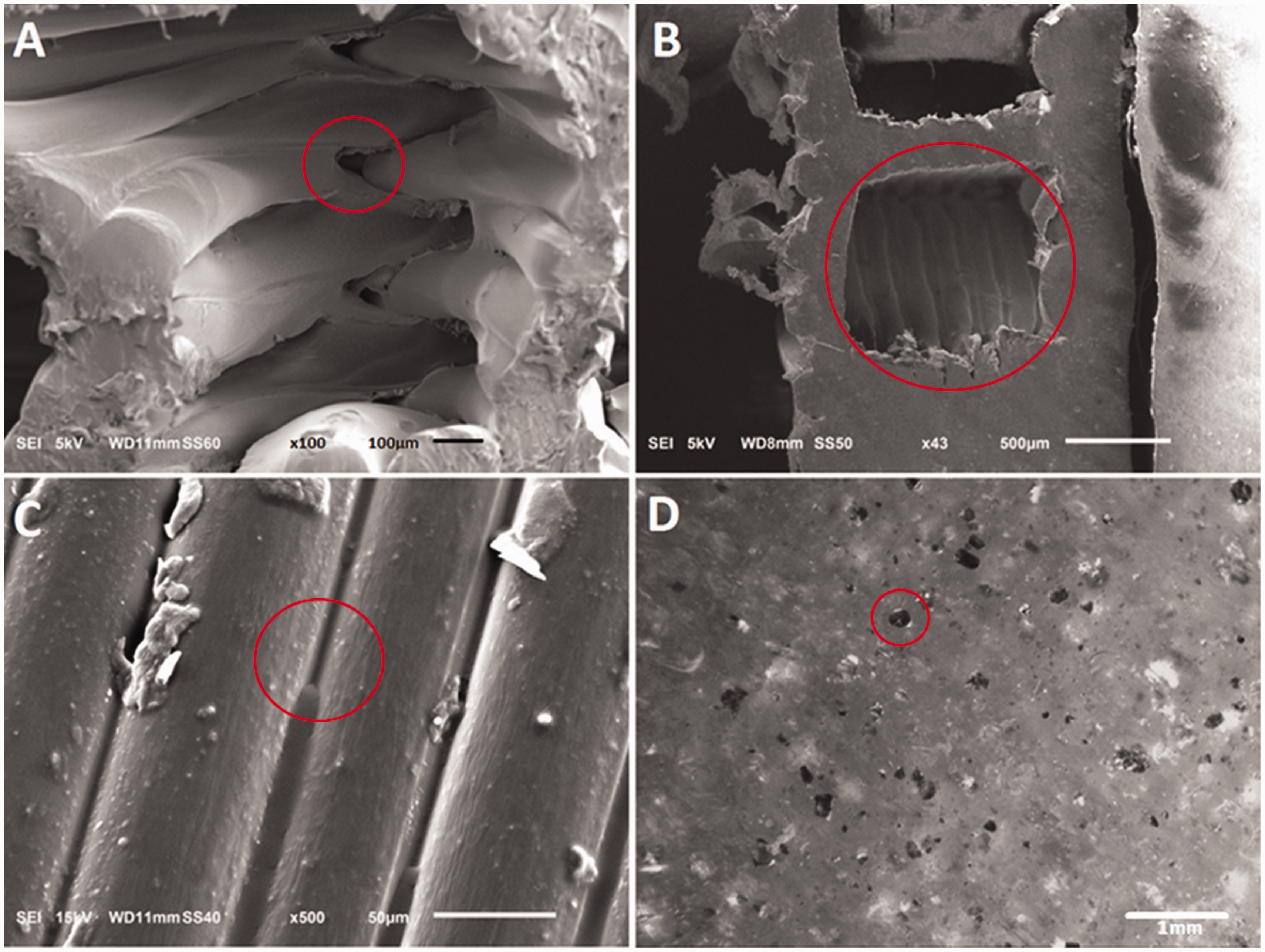
The results for PLA filament specimen is nearly the same as the previous research performed by Letcher et al., with little difference in ductile behavior which occurred due to the annealing effect of curing of epoxy and filament together in oven. 9 In their research, Letcher used coil-wrap gripping system instead of the epoxy system used in this research.
Figures 7 and 8 show the microstructure of carbon and Kevlar reinforced composites. Specimens fractured under tension were imaged under SEM. Figure 7(a) shows the poor interface between individually placed fiber tows, as well as poor bonding with the surrounding polymer matrix in Kevlar reinforced composite. Similar microstructural features were seen in Figure 7(b), for which poor fusion between fiber tows become more apparent. Ideally, polymer resin infusion will be continuous to aid stress bridging between each individually placed fiber bundle.
SEM images of failed 3D-printed samples show the cross-section of (a) carbon fiber specimen, and (b) Kevlar fiber specimen. SEM observation of fiber-matrix interface in printed carbon reinforced composites (a) poor resin infusion observed on the tow scale and (b) fiber pullout with little matrix damage evidencing weak interface strength.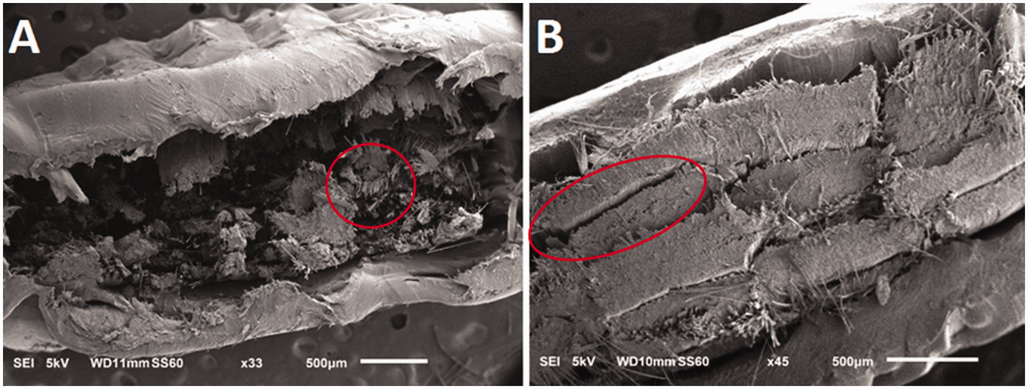
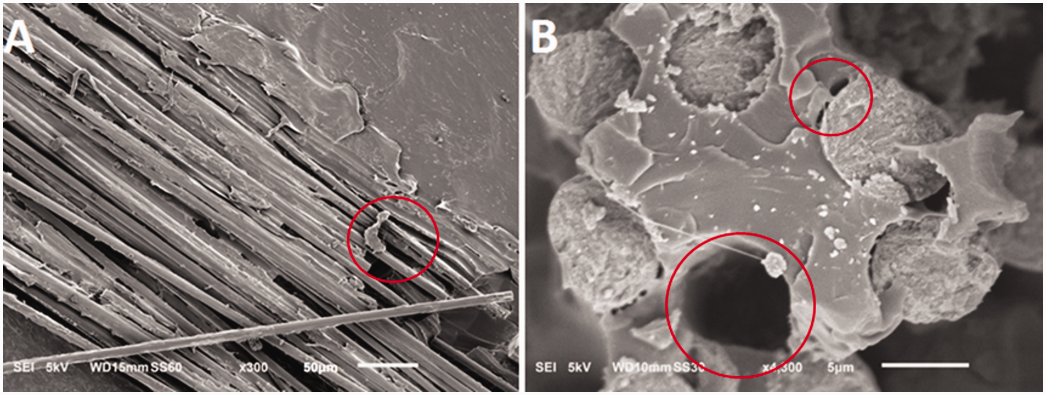
Similar microstructural features as above were also visible in carbon reinforced composites. These specimens exhibited incomplete resin infusion (Figure 8(a)), and failed specimens showed signs of a weak fiber-matrix interface strength (Figure 8(b)). For the former, the weak infusion between different sections is noticeable. This artefact is the reason behind the weakening of mechanical properties compared to the conventionally produced composites. As for the latter, in regions where fiber pullout after failure was observed, there was little sign of matrix damage, evidencing that fibers were able to pull out relatively easily. This points out the insufficiency of the bonding between the reinforcement and the matrix, which is needed to transfer the stress to reinforcement. Due to these defects in the microstructure, mechanical properties of such composites remain limited.
SEM investigation also revealed the fracture characteristics of the fiber reinforcements. Figure 9 shows that carbon fibers ruptured in a brittle manner without elongation or distortion of the broken ends, judging by the dispersed and failed carbon fibers within the geometry. However, fracture of ductile Kevlar fibers showed significant elongation and distortion in the failure section as seen from the significant deformation of Kevlar fiber bundles. These fracture micrographs show fiber-dominated failure behaviors of printed carbon and Kevlar reinforced composites are consistent with conventional composite failure modes.
SEM images of fractured fibers, (a) carbon fibers showing brittle damage morphology and (b) Kevlar fibers showing significant elongation and distortion.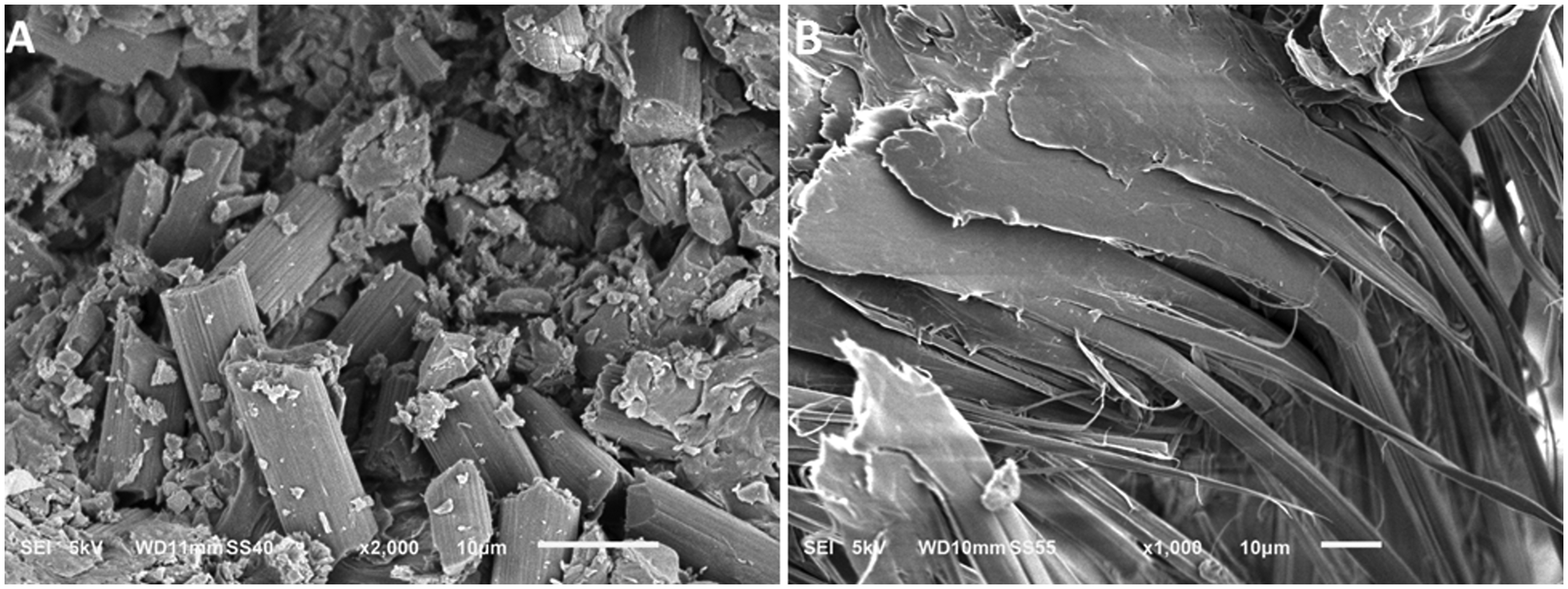
Discussion
Recent developments in additive manufacturing have made this technique a novel tool to supplement and/or replace conventional manufacturing methods. One of these developments, is to reinforce polymers with continuous and high-strength fibers and enhance their mechanical strength. In this study, we documented that nylon samples reinforced with only 14% carbon fiber in volume has strength nearly 11 times higher than that of unreinforced nylon. The strength of printed carbon fiber reinforced composites (250 MPa) was found to be similar to those of aluminum alloys commonly used for structural applications. Aluminum alloys such as 6061 and 6063 are commonly used for aerospace, marine and automotive applications. Yield strength of these alloys varies between 214 and 260 MPa and density is nearly 2710 kg/m3. Considering that 3D-printed polymer composites offer similar mechanical strength with nearly 50% less density (1400 kg/m3), these fiber reinforced composites can find wide range of commercial, industrial, and defense applications where weight reduction is indispensably important along with high strength. Comparison between 3D-printed fiber reinforced composites and traditional prepreg composites could not be done in this study since the printed composites consisted significantly low fiber amounts unlike the traditional fiber reinforced composites. Future efforts will be devoted to enhance fiber volume ratio and explore the effects of higher fiber content in the 3D-printed composites.
Although 3D printing technology offers numerous benefits over traditional composite manufacturing such as fabrication of complex-shaped products and precise control of the constituent topology within the composite, this method leads to creation of microstructural defects which are intrinsic to additive manufacturing. We reported that 3D-printed polymers and composites showed decreased strength and stiffness compared to traditional manufacturing methods as hypothesized. This was not unexpected, for a variety of reasons; despite the versatility of the process, printing introduces several additional hierarchies of microstructure to a composite material. SEM observation has been critical to identifying the unique features of printed microstructures, which occur on length scales from 10 µm to millimeter. A full volume of printed material was essentially filled line-by-line (to complete a layer) and layer-by-layer (to complete the total volume of a printed component). As such, the process introduced many microstructural interfaces between each line and each layer. Curing does not occur simultaneously throughout the part, as new material is printed upon/next to partially cured material. Thus interdiffusion is incomplete, microstructural interfaces are created, and mechanical properties were diminished. While this can be true of a printed polymer, interfaces on multiple scales are created in printed composites, as the fusion between fiber tow segments is imperfect, as is the fusion between the tow segments and surrounding polymer matrix. Additionally, whether in a composite or not, printed polymers were not degassed in this process. Unlike printing, in traditional fabrication polymers or composites, vacuum is often applied to a viscous polymer before infusion to a fiber preform or component mold, in order to remove trapped internal gas and thus microvoids in the consolidated part.
The above artifacts in microstructure suggest potential steps for process improvement, including an incorporation of resin degassing to the process, and/or applying a post-cure stage to attempt to alleviate the many extra interfaces that were created in the process as shown in Figures 7 and 8. Additionally, as there was clearly poor fiber-matrix interface, application of fiber sizing or surface treatment could potentially improve the toughness of printed composites, although weak interface does not generally contribute to lower quasi-static stiffness and strength. Such process improvements will be the focus of future studies.
In general, the microstructural artefacts of 3D printing of polymers and polymer composites can be summarized as: additional interfaces, gaps created by incomplete fill patterns, and micro voids. The mechanism of lowered stiffness is essentially the simple loss of cross-sectional area in a property that is measured on a cross-section areal basis. While this is also true of strength, the weakening effect is amplified by the stress concentrations and failure initiation points caused by voids, internal gaps, or failed interfaces (effects that are true for any material system, whether caused by a manufacturing process, material flaw, or loading).
The fiber volume fractions in the composite specimens herein were seen to be relatively low (note this is not inherent to the printing process, and higher volume fractions may be achieved). Measuring volume fractions of the constituents within fabricated composites were essential for mechanical characterization. For all composites, such measurements are often imprecise, although consistent success has been observed with the TGA process (albeit at the cost of additional needed equipment and expertise). The volume fraction in a printing process is however generally not necessarily homogeneous, i.e. there will be fiber-rich and fiber-sparse regions. Many parts no longer have one characteristic volume fraction, but rather an average volume fraction that can be measured for the whole specimen or component.
The printing process did not change the general character of the mechanical behavior or the role of the deformation behavior of the fiber. Carbon fiber reinforced specimens showed the highest strength and lowest strain to failure, while Kevlar reinforced composites showed enhanced elongation at fracture due to ductility of the Kevlar fibers. The brittle nature of the carbon fiber and ductility of the Kevlar fibers were documented with SEM micrographs as in Figure 9. In addition to the reinforcement type, fiber alignment also plays important role in mechanical properties, similar to what would be seen with traditional composite layups. Despite the close fiber volume ratios, strengths of unidirectional Kevlar specimens and samples aligned with Kevlar fibers at ±45° were significantly different. Unidirectional samples possessed 3 times higher strength when they are subjected to tensile loading at the fiber direction.
Our overarching objective in this paper is to discover and characterize the exact nature of microstructure and major flaws in continuous fiber AM processes. In addition the continuous fiber printing-specific artefacts, process parameters such as printing temperature, nozzle geometry, of build plate temperature, build environment and moisture content can affect microstructure and mechanical properties of printed materials and these effects are well documented in literature. Although the effects of these parameters are not the scope of this study, they must be always considered and these parameters must be optimized to achieve highest material performance. We have used the parameters believed by the manufacturer and ourselves to produce the best result with the current hardware and body of knowledge. Future work directly from this study will work to improve both.
Conclusions
The 3D printing process stands out as a uniquely versatile fabrication technology for various types of engineering materials. With the elimination of re-tooling needs, implementation of this process in continuous fiber polymer composite manufacturing has the potential to replace traditional methods, and fill new roles in maintaining continuous reinforcement around complex curvatures. In order to deploy 3D-printed materials as alternatives to higher-strength components, relationships between fiber content, microstructure and mechanical properties must be well-established. In this study, we investigated mechanical properties of 3D-printed polymers as well as fiber reinforced polymer composites. This study documented that 3D-printed components fail at lower stresses due to specific microstructural defects, which are intrinsic characteristics of the printing process. We observed that the 3D printing process inherently leads to various artifacts on multiple length scales which cause a detrimental effect on the mechanical properties. The 3D-printed materials in this research exhibited 30–40% weaker mechanical properties compared to the traditionally manufactured materials, manifesting the future area of focus to be improved for the printing process. Resolving these issues will open up new applications for the 3D-printed components and accelerate the recognition of 3D printing to be an established manufacturing method.
Footnotes
Acknowledgements
The authors thank John Reilly from MarkForged for his valuable comments and feedback on 3D printing of fiber reinforced composite samples.
Declaration of Conflicting Interests
The author(s) declared no potential conflicts of interest with respect to the research, authorship, and/or publication of this article.
Funding
The author(s) disclosed receipt of the following financial support for the research, authorship, and/or publication of this article: This work was supported by the NASA Florida Space Grant Consortium (FSGC) [grant number UMNNX15TO001].