
Abstract
Because of the decisive role of tow orientation in braided fabric on the mechanical performance of composite, having an accurate tow orientation prediction method for each specific mandrel shape is a cornerstone for applying circular braiding technology. This work presents a numerical method to predict the tow orientation on an irregular, constant cross-section mandrel. In this numerical method, the cross-section of the mandrel is approximated by a series of line segments, and then the surface meshes of the mandrel are generated in STL format. A set of kinematic equations, which was deduced from the simultaneous motion relationship between the translation of the take-up device and the rotation of the spools, was used to calculate the sequence of the deposition points located on the edges of surface mesh for the approximated tow orientation. Braiding experiments for various process parameters were conducted on a mandrel with a specially designed cross-section manufactured using a three-dimensional printer and the angle of the braiding tow was measured. The influence of translation speed, shape of cross-section and convergence region length on braiding angle were analysed via a comparison of the simulation results and the experimental data. Two types of variation of the braiding angles in the braided fabric and its influence factors are also discussed in detail. It was shown that the numerical method, which can rapidly predict the braiding angle for an irregular, constant cross-section mandrel, is beneficial for optimizing the process parameters for hollow composite component manufacture.
Introduction
High-performance fibres such as carbon, glass and aramid can be braided over any specific mandrel to form closed fabric reinforcements using circular braiding technology. 1 Resin is injected into the braided reinforcement with the assistance of a resin transfer moulding method. The final composite component with its designed geometry is obtained after a curing process. Compared with other fabric forming methods, such as weaving and knitting, circular braiding technology is particularly suitable for seamless hollow composite components because the spools carrying the interlacing tows run in a closed path. Owing to the requirements of high strength/mass, module/mass and anti-corrosion in the aerospace, automobile and ocean engineering sectors, metal structure components are increasingly being replaced by their composite counterparts.2,3
The structure of braided reinforced components has been found to have a significant influence on its mechanical performance. Potluri et al. 4 evaluated the flexural and tensional properties of braided composite tubes. It was shown that both the load for bending failure and the maximum torque of a composite tube increase as the braiding angle decreases. Kier et al. 5 presented an analytical model to estimate the mechanical properties for different fabric architectures. In this study, the modulus of the tension of the braided unit cell was decreased in the axial direction from 59.3 to 28.4 GPa while the braiding angle increases from 30° to 60°. Sturm and Heieck 6 carried out a study on the energy absorption capacities of differently structured braided composite frames under bending loading. The results show that the energy absorption of a composite frame can be significantly increased by varying the architecture of the braided structure. Priem et al. 7 evaluated the axial crashworthiness of the thermoplastic composite tubes with a multi-layer 2.5D braided fabric. The experimental data demonstrates that the braiding angle has an obvious effect on the peak load of glass/polypropylene composite tubes. Therefore, accurate predictions of the braiding tow orientation and consequently the braiding angle are an important for designing and manufacturing hollow braided composite components.
Ko 8 presented an equation for predicting the braiding angel on a cylinder mandrel. With it, the braiding angle can be calculated by using process parameters such as the diameter of the mandrel, rotation speed of the spool and translation speed of the take-up device. Du and Popper 9 developed an analytical model to predict the braiding angle on a mandrel with a regular cross-section. Gao et al. 10 designed a software package to calculate the fibre volume fraction and braiding angle according to the configuration of the braiding machine. Potluri et al. 11 established a detailed geometrical model for braided fabric that depends on the number of yarns carriers, rotation speed and translation speed. Rawal et al.12,13 developed a fabric geometry model on the surface of a cylindrical or conical mandrel, which considered the local sinusoidal path of the braiding tow. Roy et al. 14 have presented a new study in which they indicate the braiding angle difference around a mandrel owing to its shape and in which they also present the industrial applications of braiding for which the braiding angle is important. Meanwhile, Kyosev 15 presented a generalized model for the calculation of the tow paths of tubular and flat braided fabric. A concept for the extension of the geometrical algorithm for multifilament applications was also given in the study. Nishimoto et al. 16 reported a step response model for the braiding angle of cylindrically braided fabric to analyse the angle changes. Kessels and Akkerman 17 developed a comprehensive numerical method to calculate the braided structure on an arbitrary mandrel. The method can predict the braiding angles in a fast and efficient manner. Recently, yarn interactions and related friction behaviours were added into the numerical method for a more accurate prediction of the braiding angle. 18 Na et al. 19 developed a mathematical model for a braided structure on an arbitrary mandrel based on minimum path conditions. The model mentioned above was used to conducted extensive studies to predict the braided structure. However, the variation of the braiding tow orientation on an irregular mandrel is still not well understood and needs to be studied further.
Recently, with the rapid development of the finite element method (FEM), a yarn-scale finite element model has been gaining popularity to simulate braided fabric structures. Pickett et al.20,21 employed the explicit FEM to simulate the braiding process, and the numerical results agreed with the experimental data. Similar work was also carried out by Grave. 22 Hans et al. 23 established a detailed model for the braiding process in which the yarn was meshed as truss elements. These studies show that the braiding process simulation via FEM can provide accurate results concerning yarn paths and predict defects. However, the complex mesh and model description causes the computational cost to be significant; thus, such a description cannot satisfy the current requirement from industrial manufacturing for rapid predictions.
In this study, we present a rapid prediction method for tow orientation over mandrels with an irregular, constant cross-section. The cross-section of the mandrel is approximated by a series of line segments, and then the triangle surface meshes of the mandrel are generated in STL format. A set of kinematic equations deduced from the simultaneous motion relationship between the translation of the take-up mechanism and the rotation of the spools was used to calculate the tow trajectory points located on the edges of the surface mesh. The key variants in terms of the releasing quantity, depositing quantity and current length of the convergence region were extracted from the numerical method to analyse the effect of the initial length of the convergence region and the shape of the mandrel cross-section on the orientation of the braiding tow. The braiding experiments’ process parameters were varied, and the experiments were conducted on a mandrel with a specially designed cross-section manufactured using a 3D printer; the angle of the braiding tow was measured to compare them with the numerical results.
Braiding principles
A schematic of the circular braiding process is shown in Figure 1(a). A circular braiding machine consists of a spool track plane where two sets of spools (denoted here as clockwise and anti-clockwise spools) rotate in opposite directions with the aid of horn gears. In Figure 1(b), the geometrical model of spool is visible. The braiding tow is wound on the spool in advance. Then, the free end is guided from the carrier through the braid ring and is fixed onto the mandrel. The mandrel is pulled so that it leaves the spool trace plane along the axial direction of the machine by the take-up device. Under action synchronized between the translational motion of the mandrel and the rotational motion of the spools, the tow releasing from the spool continues to deposit onto the surface of the mandrel to form the braided sleeve. By changing the position of the guide ring, the braiding tow would be pushed and consequently the tow orientation over the mandrel would be significantly affected. The touching point between the braiding tow and the guide ring is called the contact point and the distance between the current deposition point on the mandrel and the guide ring plane is defined as the length of the convergence region. During the braiding process, the braiding tow is released from the spool and deposits on the mandrel. Thus, the convergence region length will remain constant if a balance between the tow release rate from the spool and the deposition rate on the mandrel is achieved.
The circular braiding machine. (a) Circular braiding process. (b) The spool model.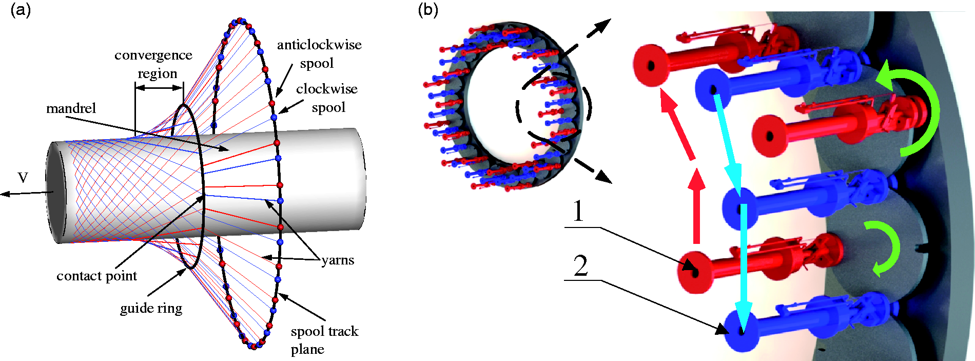
To reduce the complexity of the numerical calculation for tow orientation, the following assumptions were made. (1) There is no friction between the tow and the guide ring and no interaction between the tows. (2) The shape of the cross-section of the tows is not taken into consideration. (3) No slip occurs between the braiding tow and the mandrel after the tow deposits on the surface of the mandrel.
A kinematic model for single tow during the braiding process is depicted in Figure 2. The radius of the guide ring is defined as Rg; a contact point marked as q rotates around the mandrel with angular speed Schematic drawing of the single tow braiding process.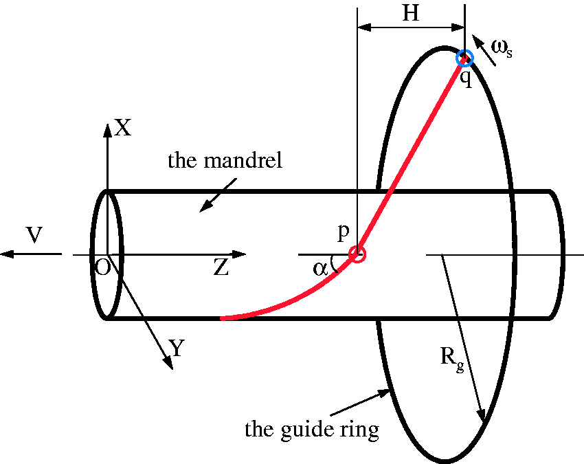
Numerical method
Governing equations
The braiding tow progressively falls on the surface of the mandrel while the contact point moves on the guide ring in the direction of the carrier rotation. There are two different types of depositing behaviour for flat and curved surfaces, respectively. The spatial relationship between the contact point and the deposition point on a mandrel that is composed of several flat surfaces is illustrated in Figure 3. In the figure, the braiding tow is braiding onto the mandrel in the clock-wise direction. It is assumed that the current deposition point is p0 and that the contact point moves from q0 to generate the next deposition point. Owing to the straight braiding tow being kept under tension, point p1 will be the next deposition point when the contact point arrives at q1, which is the intersection of the extended line from p0 to p1( The spatial relationship between the contact point and the deposition point on a mandrel with flat surfaces.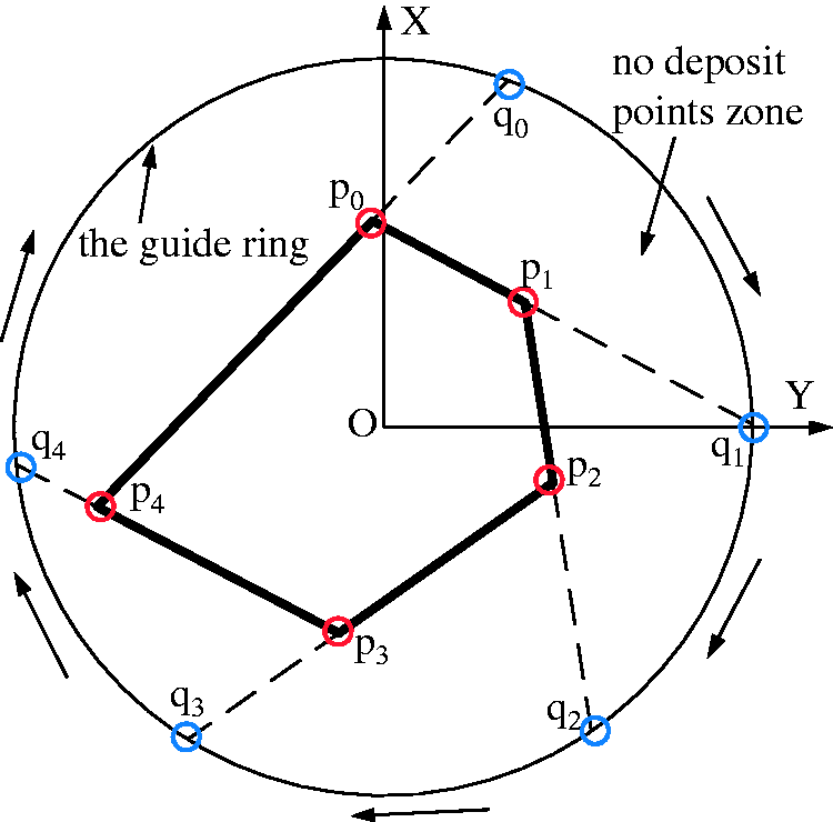
Conversely, the deposition point on a curved surface is continuous, which is illustrated in Figure 4(a). There are a large number of deposition points when the contact point moves from p0 to pn. To obtain a unifying algorithm for a mandrel with a constant cross-section that has flat and curved surface sections, the curved surface is approximated by a series of flat surfaces along the axial direction. The approximation process is shown in Figure 4(b).
Approximation method for a mandrel with a curved surface. (a) The original mandrel. (b) The mandrel’s surface approximated with flat surfaces.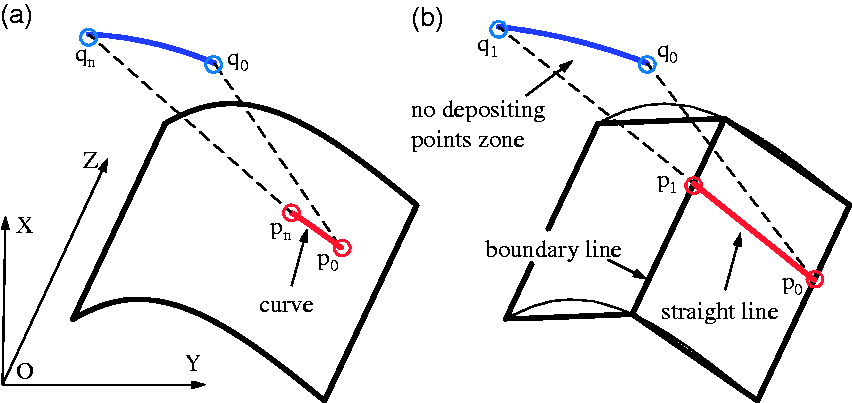
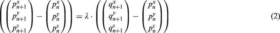
The following equations are used to calculate the coordinates of the next deposit point. The next deposition point should be on the surface of the mandrel, which can be expressed as
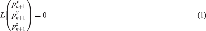
As mentioned in the previous section, the current deposition point (n), the next deposition point (n + 1) and the contact point should form a straight line owing to tension. Therefore, the following equation should be satisfied
According to the spatial relationship between the contact point and the deposition point in the X–Y plane, the positional coordinates of the contact point in the X–Y plane can be calculated using the following two equations


Owing to characteristic motions of the braiding process, the contact point rotates on the guide ring with a constant angular speed ω. Thus, the time taken to move from point qn to

Then, the position of the contact point on the z-axis is calculated by the following equation

The process mentioned above is iterated to calculate successive deposition points and consequently achieve the tow orientation. For the algorithm’s initialization conditions, the initial contact point (
Data post-processing
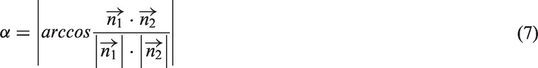
The braiding angle is important for characterizing the tow orientation; in this study, it is used to verify the effectiveness of the numerical method. It can be determined using the following equation
Calculation of the braiding angle.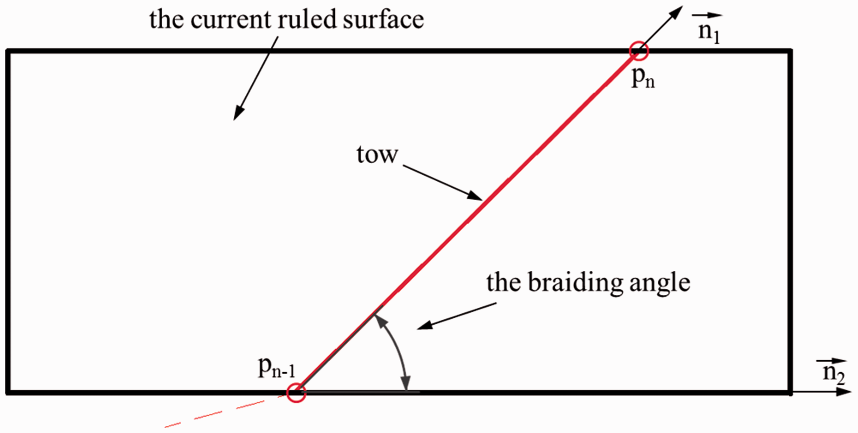
Meshing
In this section, we present a meshing method to generate the mandrel’s surface mesh so that it is suitable for the numerical algorithm. The meshing process is shown in Figure 6. A set of key nodes on the profile of the cross-section are determined according to the type of line segment, either a straight line or a curve. Those nodes are extended along the axial direction of the mandrel to form the generating lines and the related ruled surfaces. For compatibility with 3D CAD software, the mesh information is organized in the STL format, which saves the positions of the three vertices and the normal vector of each triangular facet. Therefore, a series of intersecting planes that are perpendicular to the axis of the mandrel are further generated to obtain the points were they intersect with the generating lines. Finally, two triangular facets are set from four adjacent points on a ruled surface.
Schematic illustrating the meshing process.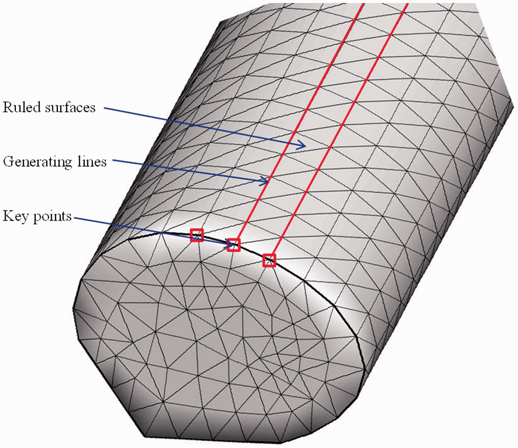
Experiment
Test bench
Figure 7(a) shows the braiding process in which a circular braiding machine with 24 spools was used to produce the fabric. A three-phase asynchronous AC motor with a gearbox was employed to drive the spools to rotate in a circular manner. As the braiding tow, a Kevlar fibre with a linear density of 1580 dtex was wound on the spools. A 500 mm mandrel with irregular constant cross-section was designed in the 3D modelling software package SolidWorks and then imported into a 3D printer’s software to be made from polylactic acid (PLA). The cross-section of the mandrel is shown in Figure 7(b). A slide with one degree of freedom driven by an AC servo motor grips the mandrel and pulls it with a programmable velocity. The braided fabric on the mandrel is depicted in Figure 7(c), and the tow orientation calculated by the simulation is illustrated in Figure 7(d).
The experimental set-up and the mandrel. (a) The circular braiding machine. (b) A diagram of the cross-section of the mandrel. (c) A photo of the braided fabric on a shape with a constant cross-section. (d) The simulated geometrical orientation.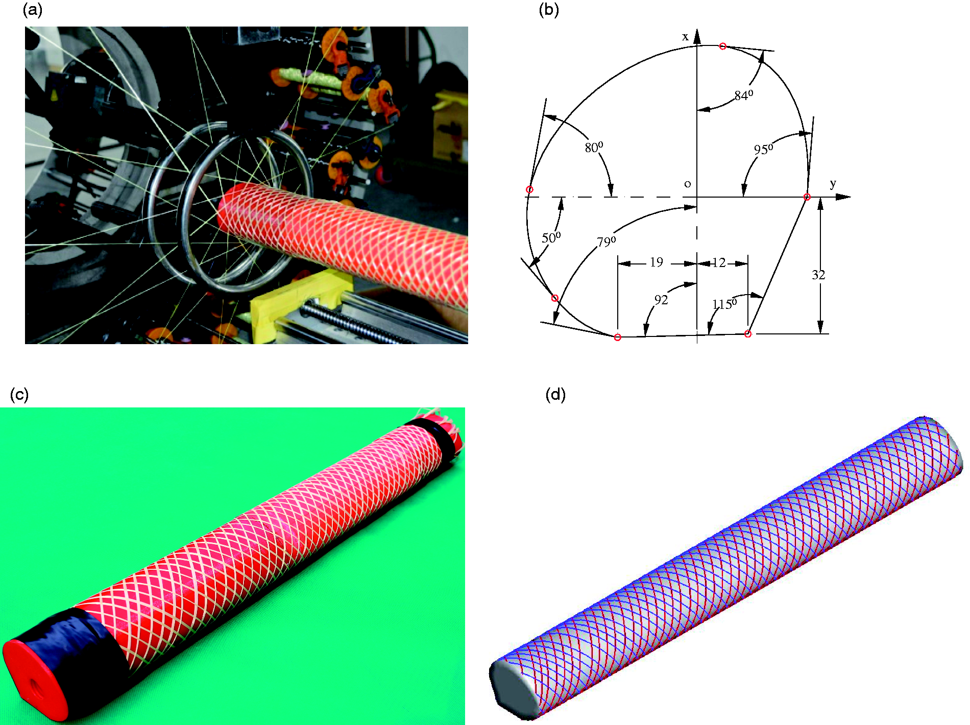
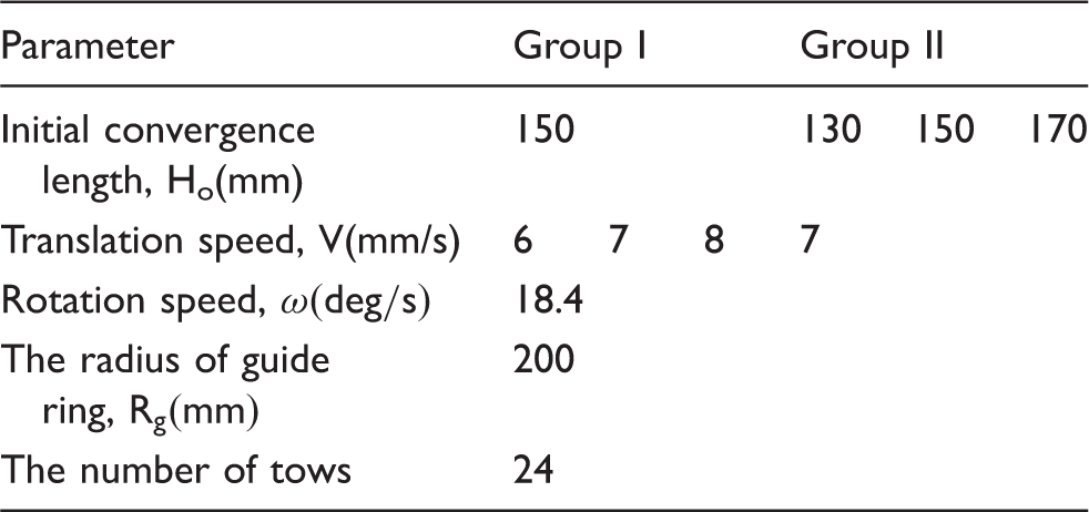
Experimental configuration
Experimental parameters used in the two groups of experiments.
Results and discussion
The effect of the translation speed on the braiding angle
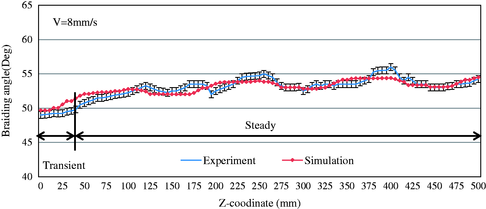
To investigate the influence of the translation speed of the take-up device on the braiding angle, three different translation speeds, namely 6, 7 and 8 mm/s, were used in Group I. The experimental and numerical results of the braiding angle of a tow along the z-axis of the mandrel are plotted in Figures 8 to 10. At the start of the braiding process the tow was fixed on the mandrel at the Z = 0 mm position and then progressively deposited toward the Z = 500 mm position. According to the curves, the maximum deviation between the numerical results and the experimental data is less than 3°; this deviation is mainly caused by the tow’s slippage on the surface of the mandrel and the interaction between the tows. In all three cases, it can be observed that the braiding angle starts at 50°. And the angle presents a rising tendency followed by a periodic variation. An average braiding angle in fluctuation was calculated in advance. Before the braiding angle enters into the 5% range of the average value for the first time, this period is defined as the transient stage. The braiding angle fluctuates around 61°, 57° and 53° when the translation speed is 6, 7 and 8 mm/s, respectively. Therefore, our results show that the average braiding angle decreases as the translation speed increases.
Variation of the braiding angle along the mandrel with a translation speed of 6 mm/s.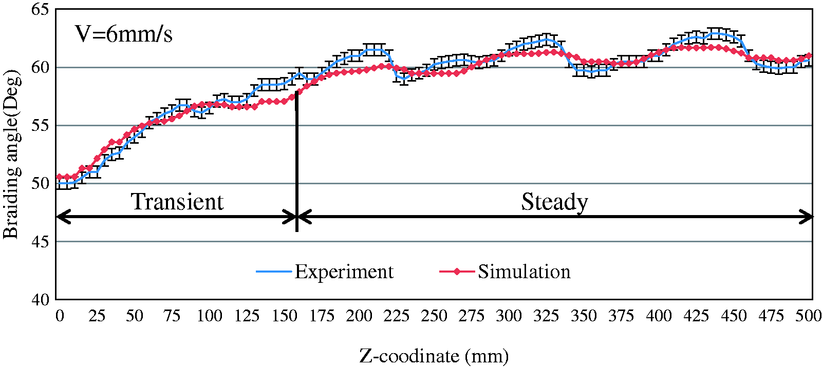
Variation of the braiding angle
From Figures 8 to 10, it can be seen that the variation of the braiding angle can be divided into two types. The initial convergence region length has a strong influence on the braiding angle at the beginning of braiding process. As the deposit point approaches to the stable convergence length, the influence induced by the factor weakens. Meanwhile, the irregular cross-section has a periodic effect on the braiding angle in the whole braiding process. Therefore, the braiding angle increases significantly in the transient stage, whereas the braiding angle shows periodic fluctuations in the following steady stage. To analyse these variations in the braided fabric structure more clearly, three process variables, namely the quantity of material released to the tow from the spool, the quantity from the tow deposited onto the mandrel, and the instantaneous length of the convergence region was extracted from the numerical results. Figure 11 presents the numerical calculation procedure. The coordinate system is fixed on the mandrel and thus the spool track plane moves to the right.
Variation of the braiding angle along the mandrel with a translation speed of 7 mm/s. Variation of the braiding angle along the mandrel with a translation speed of 8 mm/s. Schematic drawing of the numerical calculation procedure.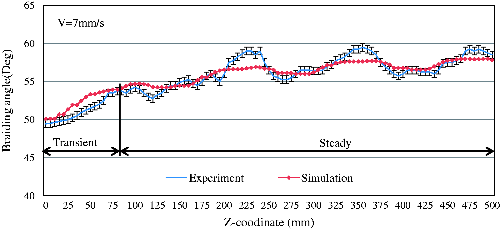
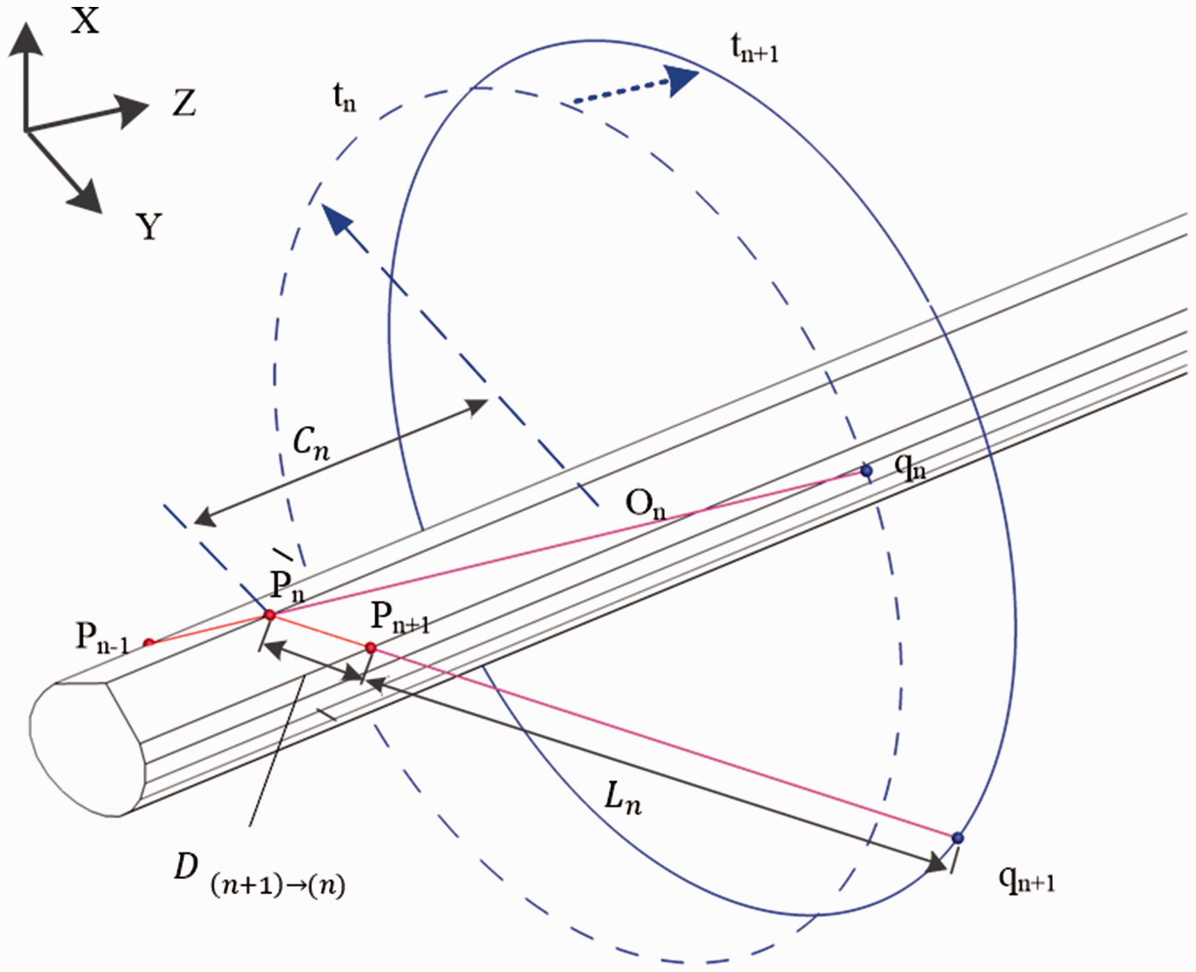
As shown in Figure 11, it is assumed that the contact point stays at position qn and that the related deposition point pn is achieved. The length of the tow in the convergence region is


As the contact point moves from the current position (qn) to the next key position (
At the same time, the quantity of the tow deposited on the mandrel can be denoted as


Angle variation in the transient stage
According to Figures 8–10, the initial braiding angle is the same for three different translation speeds, which implies that the braiding angle in the transient stage is not determined by the speed of the take-up mechanism. Therefore, experiments in Group II, which include using three different initial lengths of the convergence region (130, 150 and 170 mm), was conducted using a fixed translation speed (7 mm/s). The braiding angle in these experiments is plotted in Figure 12. The comparative results from the numerical procedure are plotted in Figure 13. The numerical results and the experimental data show a similar trend, and the initial braiding angles for convergence regions with lengths of 130, 150 and 170 mm were 46.2, 50.1 and 53.8, respectively.
Experimental braiding angles for different initial convergence lengths. Simulated braiding angles for different initial convergence lengths.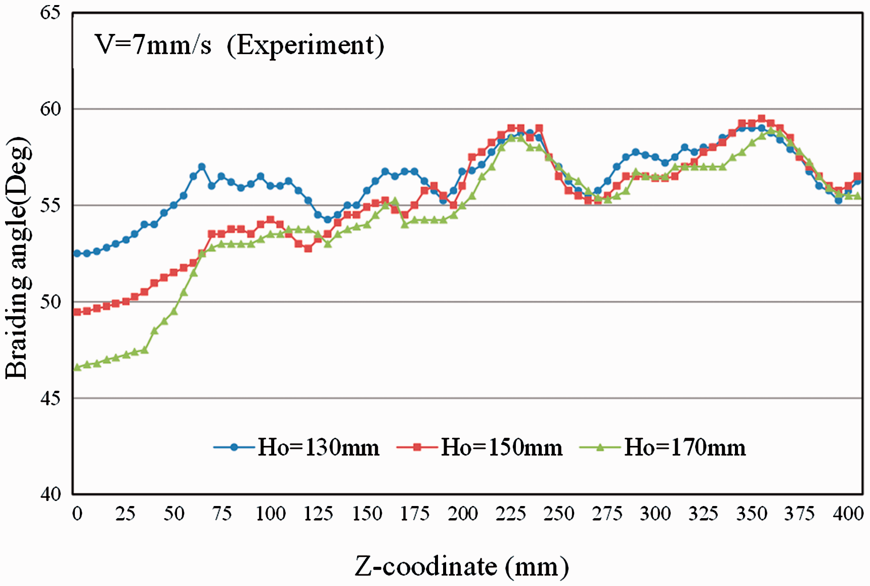
Figure 14 illustrates the depositing segments marked as S
1
, S2 and S3 on the ruled surfaces under three different braiding configurations (from H1 to H3). According to the relationship between the translational motion of the mandrel and the rotational motion of the spools, the depositing segments are formed when the contact point moves to q2 in all three configurations. Two key depositing points that fall on the edge of ruled surface in sequence are denoted as p1 and p2, respectively. Three parameters were obtained using the numerical method during the deposition of the segments, namely the deposited quantity, released quantity and braiding angle of the segments (listed in Table 2).
Influence of the convergence region length on the braiding angle. Parameters of the deposited segments for three different convergence region lengths.
As shown in Figure 14, a triangle is constructed by points p1, q2, t2 projected onto the generating line 1 from q2, since the contact point q2 is located on the extension of the plane of the ruled surface. It can be clearly observed in Figure 14 that the braiding angle decreases as the length of the convergence region increases, which is verified by the numerical results regarding the braiding angle (Table 2). The deposited quantities of the three segments S 1 , S2 and S3 were 10.92, 11.31 and 11.71 mm, respectively, while their released quantities were 6.12, 6.14 and 6.15 mm, respectively. The instantaneous deposition point will approach the plane of the guide ring, because the deposited quantity is larger than the corresponding released quantity, which causes a shorter convergence region length and consequently a smaller braiding angle in the segment deposited next to compensate for the imbalance between the two quantities. Thus, the increase of the braiding angle is observed in the transient stage. In addition, the difference between the deposited quantity and the released quantity also increased as the length of the convergence region increased, which implies that the change of the braiding angle will be more obvious for a longer initial convergence region. This can be verified via the data in Figure 13, in which the curve of the braiding angle with a longer initial convergence region has a steeper slope.
Periodic variation in the steady stage
The variation of the equivalent radius is a major characteristic of a mandrel with an irregular cross-section. To further clarify the role of the equivalent radius, two simple cylinder mandrels with and without longitudinal removal were employed. As shown in Figure 15(b), a comparison mandrel was formed by removing the part above the straight line A–B from the reference mandrel. Thus, the comparison mandrel had a smaller equivalent radius than the reference mandrel in section A–B. The braiding tow orientations on section A–B of both mandrels are depicted in Figure 15. We chose to analyse the braiding tow in the clockwise direction. A stable braiding angle on the reference mandrel could be obtained according to the equation presented by Ko
8
Effect of the equivalent radius on the braiding orientation (V = 7 mm/s and ω = 18.4 rad/s). (a) Reference mandrel. (b) Compared mandrel.
Parameters of deposited segments in section A–B.
Figure 16 shows the cross-section of the mandrel used in the experiment and the corresponding braiding angle in the stable stage. A cylindrical mandrel whose diameter was 34.28 mm was used as reference. The braiding tow fell on the mandrel with the irregular cross-section in a sequence from point a to point r, via points b, c,…,q.
Comparison of the braiding angle between two mandrels with and without an irregular cross-section. (a) X–Y representation. (b) X–Z representation.
According to Figure 16, the equivalent radius of the mandrel with the irregular cross-section decreases from point o, which causes the braiding angle to increase gradually. Although the smallest equivalent radius does not occur at point b, the smallest braiding angle is achieved at this point owing to the lag caused by the compensation of the convergence region length.
Owing to the complexity of the mandrel with the irregular cross-section, it was difficult to express the variation of the braiding structure using an analytical method. The discussion above shows that the variation of the braiding angle can be explained via the quantities generated using the numerical prediction method.
Conclusion
With the aim of rapidly predicting the braiding structure in industrial manufacturing, a numerical method to predict the orientation of the braiding tow on the surface of a mandrel with an irregular cross-section was presented. In this numerical method, the cross-section of the mandrel is approximated by a series of line segments, and then the surface meshes of the mandrel are generated in the STL format. A set of kinematic equations, which were deduced from the relationship of the motion between the translation of the take-up device and the rotation of the bobbins, was used to calculate the tow trajectory points located on the edges of the surface mesh. The braiding experiments using various process parameters were conducted on a mandrel with a specially designed cross-section manufactured using a 3D printer, and the angle of the braiding tow was measured for comparison with the numerical results. The deposited quantity, released quantity and instantaneous convergence length were extracted from the numerical results to explain the influence of the translation speed of the take-up device, the cross-section of the mandrel and the length of the convergence region on the variation of the braiding angle of the tow. The comparison between the experimental data and the numerical results showed that the numerical method can effectively predict the tow orientation for mandrels with irregular, constant cross-sections.
Footnotes
Declaration of Conflicting Interests
The author(s) declared no potential conflicts of interest with respect to the research, authorship, and/or publication of this article.
Funding
The author(s) disclosed receipt of the following financial support for the research, authorship, and/or publication of this article: This work was supported by the National Natural Science Foundation of China (grant number 51775514 and 51705466); Public Projects of Zhejiang Provincial Natural Science Foundation of China under Grant No. LR18E050001; and the 521 Talent Project of Zhejiang Sci-Tech University.