






Abstract
The interlaminar shear strengths of nanostitched 3D aramid/phenolic composites were studied. Stitching slightly improved the interlaminar strength of the z-stitching/nanotube composites. In addition, the stitching fiber type influenced the interlaminar strength of the z-stitching/nanotube aramid/phenolic composites. The failures of all structures in the compression and tensile sides were almost negligible. However, all structures had interlaminar shear failure where delamination in z-stitching/nanotube composites was arrested. The introduction of the stitching yarn in the baseline structure improved its out-of-plane failure properties without reducing the in-plane properties. The effects of stitching and multiwall carbon nanotubes on the 3D aramid/phenolic composite were encouraging and the nanostitched para-aramid/phenolic nanocomposite could be considered as damage tolerance material.
Keywords
Introduction
Fiber preforms in used composite are formed by weaving, braiding, knitting, z-pin and stitching.1,2 Fiber preforms from these techniques have continuous fibers especially in their thickness. Almost past two decades, nanoparticles were increasingly employed in fiber preform composites by dispersing or attaching the nano in the resin or filaments and filamentary fabrics using various innovative techniques.3–5 Nanotubes 6 and graphene platelets7–9 in the preforms especially in their through-the-thickness direction can act based on district principle. However, the fibers in the preform thickness can act based on continuity principle. In addition, both fiber formation and nanotubes addition techniques involved some extent complex and labor intensive processing steps.
Interlaminar shear strength was determined by using several testing methods as Iosipescu shear, double-notch shear, compressive shear and short beam shear methods. The short beam testing method was frequently employed to identify the interlaminar shear strength where sample geometry, fiber and matrix properties and preform design influenced the stress distribution along the structure width. 10 It was reported that the interlaminar strengths determined from three-point flexure (3-point bending) represented the minimum values. This is suitable as material screening tools.11,12 On the other hand, it was stated that the short beam test with 3-point flexure loading was appropriate to find the interlayer shear strength of the composite. The shear stress depended on the support span to thickness ratio and the fracture mode was predominantly interlayer matrix breakages. 13 Short beam test under four-point bending (4-point bending) was accurate due to flexure and the out-of-plane stresses were not high enough to damage the structure before interlayer shear failure, but the pure interlayer shear failure was not generated in the maximum shear stress side due to low crack propagation energy. 14 Another study claimed that the 4-point short beam was more convenient than the 3-point short beam due to the better load distribution and higher support span to thickness ratio. 15 A modified short beam shear test was developed by applying the load via a rubber pad on an aluminum plate. This loading arrangement reduced the bending and shear stress concentrations around the applied loading regions. 16 A compressive shear loading applied to the thermoplastic tubular composite length was led to have homogeneous shear stress distribution in the neutral axis, but interlaminar shear modulus in this technique was not obtained directly. 17 It was revealed that the fiber orientation and laminate lay-up were not depended with the matrix-dominated fractures under 4-point bending loading for defining the interlaminar shear strength. 18 In situ short beam shear test observation indicated that the interlaminar shear failure of E-glass/epoxy composite led to matrix and fiber damages, interlayer debonding and multiple macro-cracking. 19
Aramid fabric was dried to get rid of the absorbed water and was fluorinated. As a result, its interlaminar shear strength increased a one-third compared to the neat fabric. 20 It was reported that the warp directional interlaminar strength of E-glass/epoxy was twice that of weft direction via employing both double-notched and V-notched test method. 21 Additionally, the shear strength of the hybrid composite in warp was importantly higher compared to the filling and the hybrid composite showed high order anisotropy. 22 It was experimentally found that natural fiber hybridization with glass fiber caused increase in the interlayer shear strength due to the improved adhesion between fiber and polyester resin with chemical treatments as sodium hydroxide and sodium borohydride. 23 Another study showed that hybridization of the natural composite with glass fiber improved the interlaminar shear properties of the natural and inorganic polyester composites. 24 The hybrid composite with various stacking sequence led to considerable improvements on the composite interlayer shear properties. 25 On the other hand, it was identified that decreasing the prepreg ply thickness resulted in increasing the interlaminar shear strength due to the pseudo isotropic behavior of the thin prepreg ply. 26
The interlaminar shear strength of ceramic/silicon carbide (SiC) and SiC/SiC was obtained by using the double-notch shear method. 27 However, it resulted in low shear strength due to stress concentration around the notch regions.28,29 The influence of oxidation on 2D C/SiC via the interlaminar shear failure was defined. It was found that oxidation decreased its short beam strength. The related parameters were identified as carbon fiber diameter, interface sliding stress, matrix cracking spacing and matrix fracture energy. 30 It was also declared that porosity affected adversely to the interlayer shear strength of the 2D C/SiC composite and it was controlled by the matrix volume fraction. 31
Fiber metal laminate which was combined by aluminum with para-aramid or glass fabrics, were used for structural components of the aircraft due to their attractive fatigue and impact resistance. 32 The results demonstrated that short beam shear strength and peel strength were improved with increasing the surface roughness. 32 In addition, the short beam strength fatigue strength in the longitudinal direction of the fiber metal composite was higher than in the transverse direction. Crack growth in interlayer of the structure could prevent the catastrophic fiber failure around the matrix crack. 33
Kang and Lee 34 stated that stitching in fiber preforms enhanced the bending and tensile strength of 2D woven composites due to distribution of the load at through-the-thickness of the structure. The topological arrangements of low twist stitching fiber in the composite resulted in increasing the plane properties including interlaminar and impact strength. 35 Adversely, Mouritz et al. 36 and Mouritz 37 explained that the flexural and interlaminar strength after repeated impact of 2D stitched glass structure was reduced by stitching because of stress concentration around the stitching regions. It was found that the addition of z-yarn in biaxial fabric increased the mode-I fracture toughness of the structure at the expense of plane tensile properties. 38
The shear stress/strain of the interlayers was modeled via nonlinear spring component and Wisnom 39 found that the span/thickness ratio and material geometry were significant. The finite element modeling demonstrated that consistent results on interlaminar shear strength can be obtained for material geometry under various span/thickness ratios. 40 A symmetric double notch shear method under compression load was used to predict the maximum shear load. 41 Stitching caused defect in preform composite as a heterogeneous fiber volume fraction and yarn misalignment which was defined by a fiber distortion model. 42 Under repeated impact load, the stitched composite showed an important increase in energy absorption.34,43 In addition, under the explosive blast load, the stitched structure demonstrated high damage resistance properties due to the out-of-plane fiber in the composite. 44
It was identified that the particle size and geometry, surface area, density and purity are considered important properties for single wall (SWCNTs) and multi wall carbon nanotubes45–47 (MWCNTs). Epoxy matrix was modified by using the n-butyl glycidyl ether and MWCNT. It was reported that matrix modification led to almost 25% increase in the interlaminar shear strength of glass/epoxy composites. 48 MWCNT-(0.5%) modified glass/epoxy hybrid composite was developed by the injection double vacuum-assisted resin transfer molding (IDVARTM) technique. It was reported that no improvements were achieved in the interlaminar shear strength of the hybrid composite. 49 The apparent shear strength increased next to 15% due to homogenous carbon nanotube dispersion and nanotubes bridging in the composite layers. 50 Bilisik and Yolacan 51 demonstrated that the interlaminar shear strength of glass/nano silica composite increased with the increasing of the amount of nano silica in the composite. The direction of stitching and density, stitching yarn linear density and types as well as nano particle ratio in the composite influenced the interlaminar strength of composite. 51 Bilisik et al. 52 found that flexure properties of nanostitched p-aramid composite were slightly improved compared to the base composite. The result also showed that introducing nanostitching fiber in the base structure improved its out-of-plane failure properties as a form of restricted delamination and they acted as a delamination barrier around the region. Another study demonstrated that the fracture toughness properties of the nanostitched carbon composite showed three-fold increases compared to the base. 53 The addition of nano silicon carbide in vinyl ester resin caused to increase the tensile modulus but its tensile strength mainly depended on agglomeration of the nano particle in the resin. 54 The interlaminar strength received by short beam method of glass/nanosilica epoxy composite was enhanced due to the addition of the nanosilica 55 (0.3 wt.%). On the other hand, a one-step zinc oxide (ZnO) nanoparticle deposition in the para-aramid fiber showed significant increase in interfacial strength which was conducted by single fiber pull-out test. 56 It was shown that the interlaminar and bending strength of glass composite were considerably improved by the addition of the MWCNTs in the epoxy. 57 Zhu et al. 58 indicated that when the coated MWCNT was used, the interface strength of E-glass/vinyl ester composites was improved. Fan and Advani 59 showed that the MWCNT orientation in vinyl ester resin increased with increasing shear flow in which Brownian motion was not significant. In addition to that, the orientation of MWCNTs in the E-glass/epoxy material thickness enhanced the interlaminar shear properties conducted by 3-point short beam method. 60 It was also noted that the short beam test sample was sensitive to the functionalization of MWCNTs. 61 It was reported that the toughness of silane modified MWCNT/epoxy composite was higher compared to the acid-treated MWCNT/epoxy composite due to homogeneous dispersion and better interfacial bonding between the silane-modified MWCNT and epoxy. 62 In addition, Ma et al. 63 and Yu et al. 64 found that grafting silane onto the MWCNT surface improved the thermo-mechanical properties of the MWCNT/epoxy composite due to better interlayer adhesion and good dispersion of the nanotubes. Wang et al. 65 revealed that the short beam strength of MWNTs grown carbon fibers by chemical vapor deposition/epoxy composite was higher (103%) than the base composite.
We summarized that there were studies about effect of stitching on the in-plane and out-of-plane mechanical properties of composites. There were also studies about effect of nano materials on mechanical properties of composites but found no significant research that investigated both effect of stitching and nano materials on themechanical properties of composites. Thus, the objective of this study was to determine the effect of nano stitching on the interlaminar shear properties of woven para-aramid/phenolic composites.
Materials and methods
Z-stitching/nanotube 3D aramid/phenolic composite
Aramid Twaron® plain (1/1) fabric (CT 747, Teijin, JP) and basket (2/2) fabric (CT736) were utilized to make multistitched 3D nanopreform structures. Aramid fabric has two weave patterns as plain (1/1) and basket (2/2). The plain (1/1) fabric has interlacement one over one style in which large unit repeat (8 × 8 matrix) has interlacement as about 56 × 56, whereas the number of interlacement in basket (2/2) has 24 × 24. Thus, the number of interlacement of plain weave was higher compared to the basket weave. Figure 1 shows the plain and basket patterns with actual p-aramid fabric. The aramid fabric unit area weights were 410 g/m2 for plain and basket weaves. Their thicknesses were 0.62 mm for both plain and basket fabrics. The multiwall carbon nanotubes (MWCNTs, Nanothinx, GR) were chosen for their attractive properties, compatibility with the carbon fiber, and availability.
66
The average sizes of MWCNTs varied from 15 to 35 nm for diameter, 10 µm for length and 1–2 nm for wall thickness. Additionally, the surface area, purity and density
66
of the MWCNTs were more than 100 m2/g, equal or more than 97% and 1.74 g/cm3. The tensile strength and modulus of the bundle of 19 MWCNTs varied between 11 and 63 GPa and 270 and 950 GPa, respectively.67–68 The stitching yarns properties are also defined in Table 1.
Warp and weft directional plain (1/1) and basket (2/2) patterns are shown in schematic and actual fabric (optical microscope, magnification × 10). Specifications of untwisted stitching yarns.
52


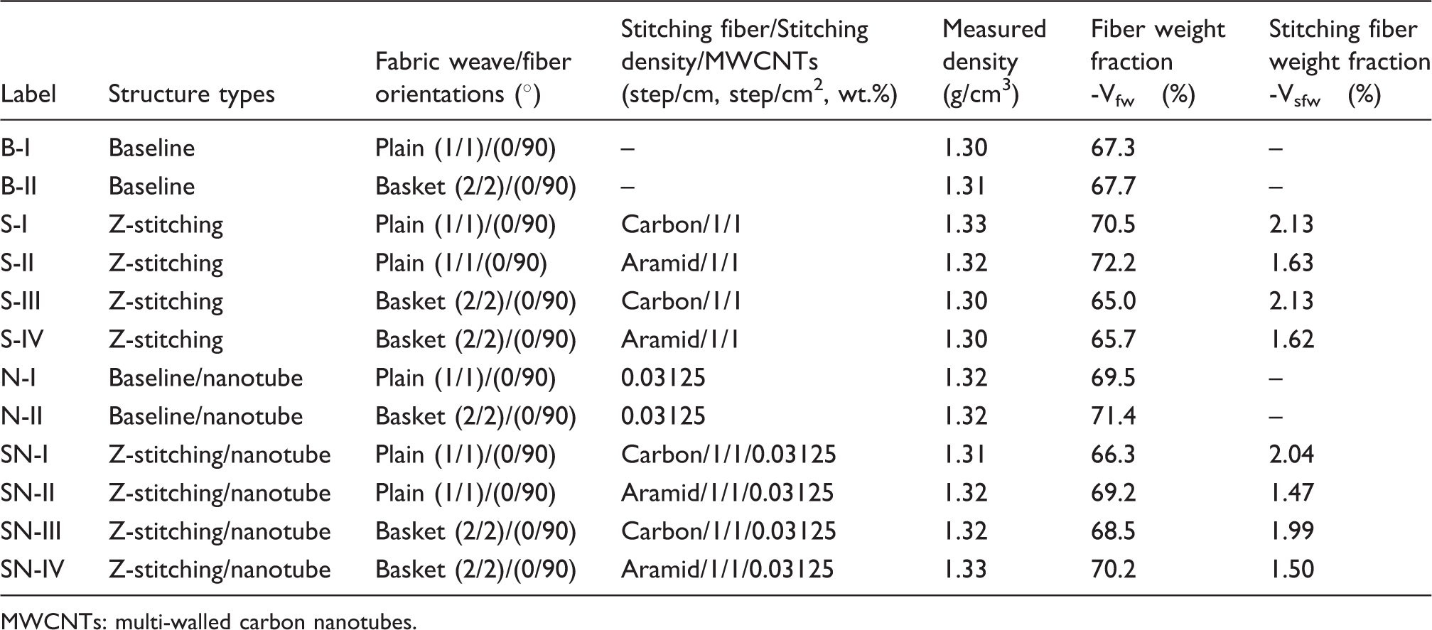
In this research, z-stitching/nanotube, z-stitching, baseline/nanotube and baseline preforms were developed and their specifications including labels are presented in Table 2. Figure 2 shows some of the z-stitching/nanotube preforms and composites as well as their schematic drawing.
Z-stitching/nanotube 3D aramid/phenolic preforms and composites. (a) Carbon z-stitching/nanotube nanoprepreg preform (left) and aramid/phenolic nanotube composite (right) (SN-III); (b) Aramid z-stitching/nanotube nanoprepreg preform (left) and aramid/phenolic nanotube composite (right) (SN-IV); (c) schematic view of carbon z-stitching/nanotube aramid nanostructure (S-III); (d) schematic cross-sectional view of p-aramid stitched/nanotube aramid nanostructure (S-IV); and (e) schematic view of aramid z-stitching/nanotube aramid nanostructure (S-IV). Specifications of developed multistitched p-aramid/phenolic MWCNTs composites. MWCNTs: multi-walled carbon nanotubes.
Z-stitching/nanotube multilayer p-aramid woven preforms were consolidated to make z-stitching/nanotube p-aramid composites.52–53 The processing steps of the z-stitching/nanotube composite structure are explained in Figure 3. In composite fabrication process, phenolic resin (Araldite EPN 1138) was mixed with the multiwall carbon nanotubes (0.03125, %wt.) via a magnetic mixer (Wisestir®) at 240 r/min for 15 min. The phenolic resin/MWCNTs mixture was mixed in an ultrasonic bath (200 W, DAIHAN/WiseClean®) at 25℃ for 60 min. Then, the mixture was once again stirred in the magnetic mixer to reduce the agglomerations. After the moisture was evaporated from the fabrics and stitching yarns, the mixture was applied to the fabric and yarns by the hand-layup technique.
52
They were pre-cured at 110℃ for 7 min to obtain the prepreg nano yarn and fabrics. The prepreg nanopara-aramid fabric was layered as a [0°/90°]6 sequence as shown schematically in Figure 2(b). The six-layered prepreg nanopara-aramid preform was manually stitched by carbon or p-aramid nano stitching yarn using an in-house developed stitching rig in order to make the nanostitched/nanocomposite. Density of stitching was 1 step per cm. The space between the neighboring stitching lines was 1 cm. The nano stitched and nano prepreg structure was cured under 0.6 MPa pressure and at 170℃ for 120 min. Thus, the nanostitched/nanocomposite was manufactured.
Fabrication steps of aramid z-stitching/nanotube aramid/phenolic prepreg preform and nano composite
69
(SN-IV).
Short beam test
The short beam test of the developed composites was fulfilled on a Shimadzu AG-XD 50 (Japan) tester equipped with Trapezium® software with a 5 kN loading cell based on ASTM D2344-13.
70
Figure 4 shows the initial position and failure of the composite sample during short beam test where 3-point bending fixture was employed. The speed of test was 1.0 mm/min. The average measured dimensions of test sample were 11.000 (width) × 36.200 (length) × 4.0123 (thickness) mm. The support span length to sample thickness was 4.985/1. It was almost appropriate to obtain pure shear from the short beam test method.23,70 The load applied to each sample was the warp (0°, lengthwise) direction. The test was conducted at the standard laboratory atmosphere having a temperature of 23℃ ± 2℃ and a relative humidity of 50% ± 10%.
(a) Short beam fixture with stitched sample at initial state (S-IV); (b) failed stitched sample under short beam load (S-IV); and (c) failed stitched/nano sample (SN-III, digital image).
Under applied load, the flexural stresses were compressive on the sample top surface and tensile on the bottom surface, varying linearly through the sample thickness within the material elastic limits. If the stress concentration around the applied load and support points was ignored, it was on the neutral plane that the interlaminar shear stress was assumed at maximum, varying parabolically from zero on each surface of the sample. Therefore, the stress state should be pure shear on the neutral plane. The bending stresses were kept low (span length/sample thickness ratio low), promoting shear failures on the neutral plane.
71
In the ASTM D 2344 standard, equation (1) shows the interlaminar shear strength under 3-point bending loading
70

In addition, the densities of the z-stitching/nanotube carbon composites were obtained by ASTM D792-91. 72 The composite volume fraction (weight fraction%) and void content were found by ASTM D3171-99 73 and ASTM D2734-91, 74 respectively. After the test, the delaminated areas and damaged surfaces of the composite sample were investigated by field emission scanning electron microscope (FESEM, ZEISS GeminiSEM500, Germany) and an optical microscope (Olympus SZ61, Japan).
Results and discussion
Density and fiber volume fraction results
The density and fiber volume fraction results of baseline (unstitched, B-I and B-II), z-stitching (S-I, S-II, S-III and S-IV), baseline/nanotube (unstitched/nano, N-I and N-II) and z-stitching/nanotube (SN-I, SN-II, SN-III and SN-IV) composites are presented in Table 2. These results considered that all composites were manufactured in appropriate processing conditions in order to carefully prepare the testing samples.
Short beam results
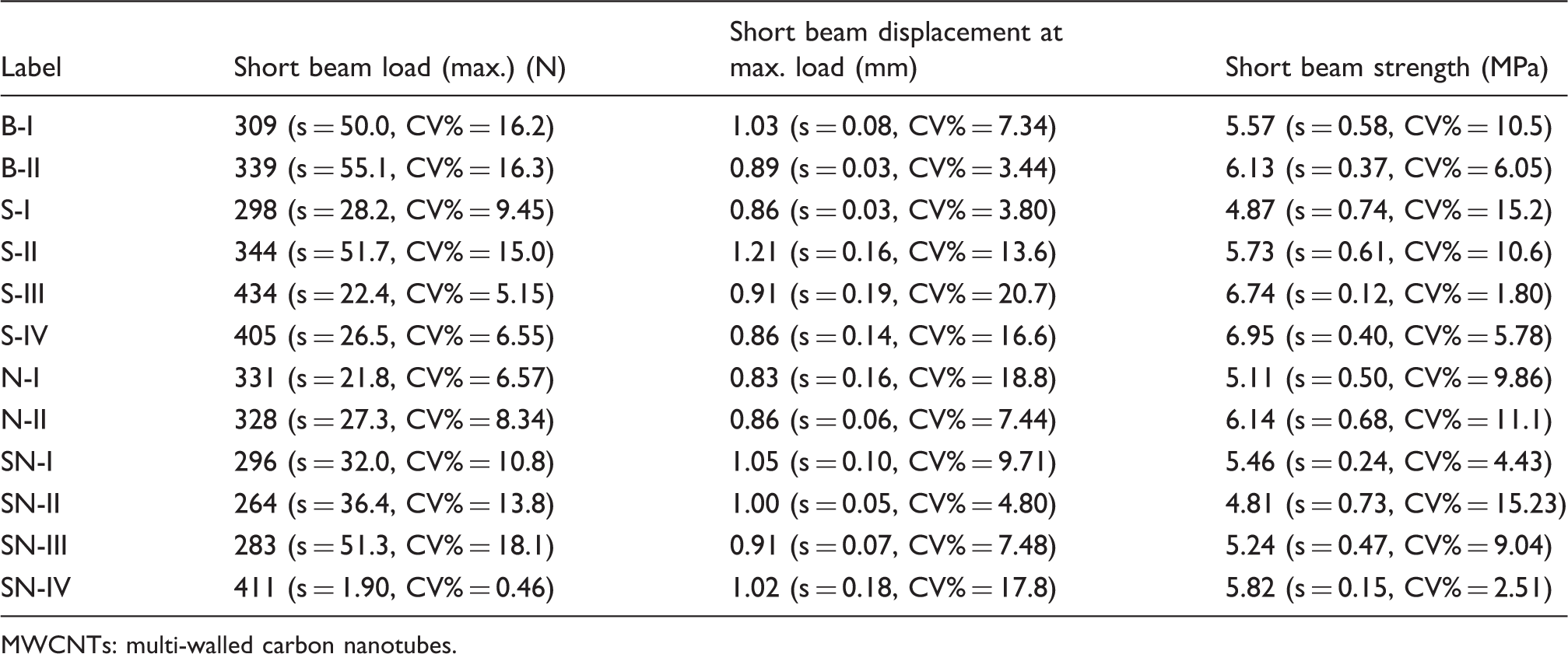
Short beam test results including standard deviation (±s) and coefficient of variations (CV%) of developed p-aramid/phenolic MWCNTs composites.
MWCNTs: multi-walled carbon nanotubes.
Figure 5(a) and (b) shows the short beam stress–strain curves of some of the basket (2/2) and plain(1/1) fabric-based composites. In Figure 5(a) and (b), the stress–strain curves of the basket and plain aramid/phenolic structures are presented together with its baseline, baseline/nanotube, p-aramid z-stitching, and z-stitching/nanotube. The initial stress was slightly quadratic for basket structures but they were almost perfectly quadratic and deviated for plain structures. Then, they rose almost linearly for both basket and plain composite structures. After that, the stress values fell sharply at the point of maximum load indicating that a major interlayer and probably minor in-plane fiber failures occurred. After the modest quadratic increase in the load probably indicating crack arrest at the failed region, the curvilinear decreasing in stress occurred until the complete fracture in the failed structure was obtained. In addition, the stress–strain curves almost perfectly become a same line at the elastic region to the major failure points for basket structures. However, they were largely deviated for plain composite structures, especially z-stitching structure due to considerable initial shear deformation generated during short beam loading.
Stress–strain curves from short beam test for some of the multistitched aramid/phenolic MWCNTs composites. (a) Basket (2/2) woven baseline (B-II), baseline/nanotube (N-II), z-stitching (S-III) and z-stitching/nanotube (SN-III) aramid/phenolic composites; and (b) plain (1/1) woven baseline (B-I), baseline/nanotube (N-I), z-stitching (S-II) and z-stitching/nanotube (SN-II) aramid/phenolic composites.
Short beam strength
Figure 6 shows the average short beam strength values of all the developed p-aramid/phenolic MWCNT composites. The in-plane tensile strengths of all the p-aramid/phenolic MWCNTs composites are also provided in Figure 6 from Bilisik et al.
75
for comparison purposes. In Figure 6 and Table 3, the short beam strength of the baseline (B-I and B-II) composites varied between 5.57 and 6.13 MPa, whereas the short beam strength of the baseline/nanotube (N-I and N-II) composites varied between 5.11 and 6.14 MPa. The short beam strength of the z-stitching (S-I, S-II, S-III and S-IV) composites varied between 4.87 and 6.95 MPa, whereas the short beam strength of the z-stitching/nanotube (SN-I, SN-II, SN-III and SN-IV) composites varied between 4.81 and 5.82 MPa. The short beam strength of the aramid z-stitching basket 2/2 (S-IV) composite was slightly higher (11.66%) than baseline/nanotube (N-II), and it was 11.80% higher than baseline (B-II) composite. It was also 16.26% higher than z-stitching/nanotube (SN-IV) composites. In addition, the short beam strength of the z-stitching basket 2/2 (S-IV) was hardly higher (3.02%) compared to the PAN carbon z-stitching (S-III), and it was 24.60% higher than z-stitching/nanotube (SN-III) composite. Also, the baseline/nanotube (N-II) was almost the same to the baseline (B-II) composite. The aramid nanostitched composite (SN-IV) showed slightly better performance compared to the carbon nanostitched composite (SN-III). It was realized that z-stitching slightly increased the short beam strength of all baseline composites. The stitching yarn type slightly affected the short beam strength of the z-stitching and z-stitching/nanotube composites. The effect of the MWCNT was not identified clearly and its contribution on the short beam strength was insignificant. This indicated that more studies are required, especially on its interlaminar strength with regard to filament and matrix in composite as filament-nanotube bonding, matrix-nanotube bonding and boundaries during stress transfer mechanism and strengthening mechanism as well as MWCNTs off-axis positioning in-plane and out-of-plane of the composite. This is our future research priority to understand the MWCNTs property transfer mechanism. On the other hand, we did not obtain the similar result from the p-aramid plain 1/1 structures and the results received from the baseline (B-I), baseline/nanotube (N-I), z-stitching (S-I and S-II) and z-stitching/nanotube (SN-I and SN-II) structures were slightly inconsistent. On the other hand, as exhibited in Figure 6, in-plane tensile strengths of the z-stitching, baseline/nanotube and z-stitching/nanotube were slightly better than that of the baseline composites. This was considered that adding z-stitching and nanotubes to the baseline enhanced its out-of-plane properties without reducing its in-plane properties.
Short beam strength and in-plane tensile strength
75
of various aramid/phenolic MWCNT composites.
Figure 7 shows the average short beam load values of all the developed p-aramid/phenolic MWCNT composites. In Figure 7 and Table 3, the short beam load of the baseline (B-I and B-II) composites varied between 309 and 339 N, whereas the short beam load of the baseline/nanotube (N-I and N-II) composites varied between 331 and 328 N. The short beam load of the z-stitching (S-I, S-II, S-III and S-IV) composites varied between 298 and 434 N, whereas the short beam load of the z-stitching/nanotube (SN-I, SN-II, SN-III, SN-IV) composites varied between 264 and 411 N. The short beam load of the p-aramid z-stitching basket 2/2 (S-IV) composite was higher (18.95%) for baseline/nanotube (N-II) and 16.21% higher for base (B-II) but it was hardly lower (1.57%) for z-stitching/nanotube (SN-IV), whereas the short beam load of the z-stitching (S-IV) was slightly lower (6.71%) than PAN carbon z-stitching (S-III) and was 30.10% higher than z-stitching/nanotube (SN-III). Also, the baseline/nanotube (N-II) was 3.27% lower than baseline (B-II) structure. The p-aramid nanostitched structure (S-IV) showed better performance compared to the baseline (B-II) and baseline/nanotube (N-II) structures. It was found that stitched fibers somewhat increased the short beam load of all baseline composites. The effects of stitching fiber type on the short beam load of the z-stitching and z-stitching/MWCNTs composites were slightly significant. In addition to that, the contribution of the MWCNT on the short beam load was not identified clearly. In the case of the p-aramid plain 1/1 composites, we did not receive consistent result especially from the baseline (B-I), baseline/nanotube (N-I), z-stitching (S-I and S-II) and z-stitching/nanotube (SN-I and SN-II) composites.
Short beam load of various aramid/phenolic MWCNT composites.
Figure 8 shows the average short beam displacement values of all the developed p-aramid/phenolic MWCNT composites. In Figure 8 and Table 3, the short beam displacement of the baseline (B-I and B-II) composites varied between 1.03 and 0.89 mm, whereas the short beam displacement of the baseline/nanotube (N-I and N-II) composites varied between 0.83 and 0.86 mm. The short beam displacement of the z-stitching (S-I, S-II, S-III and S-IV) composites varied between 0.86 and 1.21 mm, whereas the short beam displacement of the z-stitching/nanotube (SN-I, SN-II, SN-III and SN-IV) composites varied between 0.91 and 1.05 mm. The short beam displacement of the p-aramid z-stitching basket 2/2 (S-IV) composite was the same to the baseline/nanotube (N-II) and was 3.37% low for the baseline (B-II) and 15.69% low for the z-stitching/nanotube (SN-IV), whereas the short beam displacement of the z-stitching (S-IV) was slightly low (5.50%) compared to PAN carbon z-stitching (S-III) and the z-stitching/nanotube (SN-III). Also, the baseline/nanotube (N-II) was 3.37% lower than baseline (B-II) structure. The stitching and stitching yarn types as well as MWCNTs affected slightly the short beam displacement of the z-stitching and z-stitching/nanotube composites.
Short beam displacement of various developed aramid/phenolic MWCNTs composites.
Failure after short beam test results
Some of the short beam failures of baseline (B-II), baseline/nanotube (N-II), z-stitching (S-IV and S-III) and z-stitching/nanotube (SN-II and SN-I) composites are shown in Figures 9 to 20.
Warp directional short beam failure in multilayered unstitched basket (2/2) p-aramid/phenolic composite. (a) Baseline bottom face (B-II); (b) baseline cross-section (B-II); and (c) baseline top face (B-II) (optical microscope, magnification × 6.7).
Tension side of the baseline (B-II) and baseline/nanotube (N-II) structures had outwardly lateral deformation but they had no visible macro failure in the structure surfaces as shown in Figures 9(a) and 10(a). In the compression side of both structures, they had inward lateral minor matrix breakages and peeling on the surfaces (Figures 9(c) and 10(c)). In the cross-section of the B-II and N-II, several local interlaminar shear failures around the mid-plane of the structure thickness were observed. A few of layer separation were angularly sheared in the through-the-thickness direction, and layer openings in the N-II structure were large compared to the B-II. In addition, layer opening in both structure was comparably propagated as shown in Figures 9(b) and 10(b), respectively.
Warp directional short beam failure in multilayered unstitched basket (2/2) p-aramid/phenolic MWCNT composite. (a) Baseline/nanotube bottom face (N-II); (b) baseline/nanotube cross-section (N-II); and (c) baseline/nanotube top face (N-II) (optical microscope, magnification × 6.7).
In the cross-section of the B-I, pure interlaminar shear failures in the neutral axis of the structure thickness were observed as a form of crack propagation due to interlayer matrix breakages (Figure 11(a)), whereas multiple local layer openings in the N-I structure were found as shown in Figure 11(b).
Warp directional short beam failure in multilayered unstitched and nanotube plain (1/1) p-aramid/phenolic composite. (a) Baseline cross-section (B-I) and (b) baseline/nanotube cross-section (N-I) (optical microscope, magnification × 6.7).
Inside fracture surfaces of the baseline/nanotube structure were analyzed by considering Figure 12(a) and (b). The warp directional long matrix failure especially boundary of the filaments was found as a form of local shear hackle. The nanotubes were perfectly coated by the phenolic resin and their dimensions varied from 16.10 nm to 50.92 nm. However, there were large agglomeration, especially unmeasured nanotubes in the failed interlayer surface (Figure 12(b)). More study is required to identify nanotube responses in the matrix under the short beam load.
SEM views of interlaminar failure of the inside fractured surface of unstitched basket (2/2) p-aramid/phenolic MWCNT composite. (a) Inside surface of the baseline/nanotube composite (N-II, scale bar 20 µm; magnification × 200); and (b) MWCNTs dispersion in the inside surface of the baseline/nanotube composite (N-II, scale bar 200 nm; magnification × 50,000).
Tension side of the z-stitching (S-IV) and (S-III) structures had outward strained area around the stitching loop and had no visible matrix or filament breakages as shown in Figures 13(a) and 14(a). In the compression side of both structures, they had inward lateral a dented area around the stitching loop sections (Figures 13(c) and 14(c)). In the cross-section of the S-IV and S-III, a few local interlaminar shear failures around the mid-plane of the structure thickness were observed. Almost no angularly sheared failure and layer openings in the through-the-thickness direction were identified. Layer opening in both structures was locally restricted due to one-directional stitching as shown in Figures 13(b) and 14(b), respectively. Importantly, there were no failed z-stitching yarn in the local interlaminar shear failure area. It can be interpreted that layer-to-layer opening occurred in the matrix layer and spread around the stitching yarn region where stitching yarn holds adjacent layers in the through-the-thickness to prevent catastrophic layer separation.
Warp directional short beam failure in Twaron z-stitching basket (2/2) p-aramid/phenolic composites. (a) Twaron z-stitching bottom face (S-IV); (b) Twaron z-stitching cross-section (S-IV); and (c) Twaron z-stitching top face (S-IV) (optical microscope, magnification × 6.7). Warp directional short beam failure in PAN carbon z-stitching basket (2/2) aramid/phenolic composites. (a) carbon z-stitching bottom face (S-III); (b) carbon z-stitching cross-section (S-III); and (c) carbon z-stitching top face (S-III) (optical microscope, magnification × 6.7).

Inside fracture surfaces of the z-stitching/nanotube structure (SN-III) were analyzed by considering Figure 15(a) and (b). The warp directional matrix-filament peeling and a few in-plane filament breakages were found (Figure 15(a)). In the close view of the fractured layer, we identified matrix-filament debonding in the filament boundary and matrix failure as a form of shear hackles due to out-of-plane short beam loading (Figure 15(b)).
SEM exhibitions of the inside surface of nanocarbon z-stitching basket (2/2) p-aramid/phenolic MWCNT composite. (a) Nanocarbon z-stitching inside layer after short beam test (SN-III, scale bar 20 µm; magnification × 750); and (b) Matrix failure in nanocarbon z-stitching composite after the short beam test (SN-III, scale bar 2 µm; magnification × 4000).
Inside fracture surfaces of the z-stitching/nanotube structure (SN-IV) were analyzed via Figure 16(a) and (b). The vertical lines in the normal to the warp direction in-plane matrix-filament breakages were observed and a few in-plane matrix breakages parallel to the warp direction were also found (Figure 16(a)). However, there were no nanostitching yarn failures. The nanostitching yarn acted as a interlayer crack barrier around the failed zone. In the close view of the fractured layer, we identified large matrix crack parallel to the filament axis near to the filament boundary where MWCNTs were identified. We address the future study about filament-nanotube bonding and their position as well as their contribution to stress transfer mechanism in the matrix environment (Figure 16(b)).
SEM illustration of the fractured surface of nanop-aramid z-stitching basket (2/2) aramid/phenolic MWCNT composite. (a) Nanop-aramid z-stitching composite (SN-IV, scale bar 20 µm; magnification × 200); and (b) matrix fracture in nanop-aramid z-stitching composite (SN-IV, scale bar 1 µm; magnification × 6710).
In the cross-section of the S-II and SN-II, a minor local interlaminar shear failures around the mid-plane of the structure thickness were observed. Interlayer opening in both structures was locally restricted due to one-directional p-aramid stitching as shown in Figure 17(a) and (b).
Warp directional short beam failure in Twaron z-stitching and z-stitching/nanotube plain (1/1) p-aramid/phenolic composites. (a) Twaron z-stitching cross-section (S-II); and (b) Twaron z-stitching/nanotube cross-section (SN-II) (optical microscope, magnification × 6.7).
Inside fracture surfaces of the z-stitching/nanotube structure (SN-II) were considered via Figure 18(a) to (c). The unfailed nano z-stitching inside the fractured surface was deliberately cut to open the surface for the SEM analysis. As exhibited in Figure 18(a), stitched opening to insert the out-of-plane nanostitching was identified. Near to the stitched opening area, warp and filling directional matrix-filament breakages were obtained. In addition, fibrillar filament peeling and matrix breakages were found probably due to interlayer matrix-filament-nanotubes frictional and abrasion action during out-of-plane short beam load (Figure 18(b)). In the same region, multiple longitudinal matrix crack band was found where MWCNTs were located (Figure 18(c)).
SEM views of fractured layers of nanop-aramid z-stitching plain (1/1) p-aramid/phenolic MWCNT composites. (a) Inside layer of nanop-aramid z-stitching/nanotube composite (SN-II, scale bar 100 µm; magnification × 81); and (b) fractured surface of nanop-aramid z-stitching/nanotube composite (SN-II, scale bar 20 µm; magnification × 250); (c) MWCNTs placement on the fractured phenolic matrix (SN-II, scale bar 200 nm; magnification × 30,000).
The multiple regional interlaminar shear failures in the mid-plane of the S-I and SN-I composite thicknesses were identified. Layer-to-layer delamination in the S-I and SN-I composites was regionally arrested due to one-directional PAN carbon stitching as shown in Figure 19(a) and (b).
Warp directional short beam failure in PAN carbon z-stitching and z-stitching/nanotube plain (1/1) aramid/phenolic composites. (a) carbon z-stitching cross-section (S-I); and (b) carbon z-stitching/nanotube cross-section (SN-I) (optical microscope, magnification × 6.7).
One of the short beam failures of z-stitching/nanotube (SN-I) and (SN-II) composites are shown in Figure 20(a) to (c). In the cross-section of the SN-I, inelastic deformation failure mode was obtained. Additionally, angularly oriented interlaminar shear failures around carbon stitching yarn loop in the tension side of the sample were observed as shown in Figure 20(a). It is clearly seen that stitching line acted like a crack propagation blocker based on continuity principals. As shown in Figure 20(b), layer-to-layer multiple interlayer shear failure in the mid-plane of the structure thickness was angularly obtained. The edge side interlaminar shear opening mode was found in the z-stitching/nanotube (SN-IV) structure as illustrated in Figure 20(c).
Warp directional short beam failure in plain(1/1) z-stitching/nanotube aramid/phenolic composites. (a) carbon z-stitching/nanotube cross-section (SN-I); (b) p-aramid z-stitching/nanotube cross-section (SN-II); and (c) p-aramid z-stitching/nanotube (SN-II) (optical microscope, magnification × 6.7).
Conclusions
Z-stitching and z-stitching/nanotube aramid/phenolic composites were manufactured and their short beam properties were investigated. Also, short beam failures of those composites were identified. The stitching slightly increased the short beam strength of all the z-stitching and z stitching/nanotube composites. However, consistent results at all the baseline/nanotube, z-stitching, and z-stitching/nanotube composites were not obtained. It was also found that the type of stitching yarn slightly affected the short beam properties of the developed aramid/phenolic composites.
The short beam failure in the tension and compression side of all structures was almost negligible. The short beam failure in the cross-section of the baseline and baseline/nanotube structures had angularly interlaminar shear in through-the-thickness layer separation, whereas the z-stitching and z-stitching/nano composites had restricted short interlaminar shear failures. The result showed that the addition of the few percent stitching fiber (1.81%) and nanotubes (0.03125%) in the baseline structure improved the interlaminar strength and the out-of-plane failure properties without reducing the in-plane properties, and could be considered as damage tolerance material. In future, more study is required for the effect of carbon nanotube placement on the para-aramid/phenolic composite.
Footnotes
Acknowledgements
The authors would like to thank Dr. N. Sahbaz for helping to make the composite samples. In addition, the authors would also like to thank S. Gungor for some useful discussions on carbon nanotube processing.
Declaration of Conflicting Interests
The author(s) declared no potential conflicts of interest with respect to the research, authorship, and/or publication of this article.
Funding
The author(s) disclosed receipt of the following financial support for the research, authorship, and/or publication of this article: This work was supported by Roketsan Industries Grant No. RS/ERCİYES DSM-76301-14-01N/R.