






Abstract
Titanium aluminium carbide powder was reaction synthesized and used as reinforcement in the aircraft grade epoxy matrix (LY556) to develop a high-performance conductive polymer composite. The particle sizes of 4 and 7 µm were employed from 0 to 40 wt.% to improve the mechanical and electrical properties of conductive polymer composites. It was observed that the percolation characteristics were exhibited at a critical threshold of 20 wt.% for both the filler particle sizes. Further, microstructural observations revealed the formation of a conductive network in the conductive polymer composites when the filler content was 20 wt.%. The tensile and flexural properties were increased when the particle size was decreased. Experimental values were then compared with the available analytical models for validation. The mechanical and electrical properties of the conductive polymer composites were optimized by tailoring the filler particle size to 4 µm and particle loading at 20 wt.%. Compared to neat epoxy, the optimized conductive polymer composites have shown a simultaneous increase in strength, stiffness and conductivity performances, which can find applications in aerospace and electronics industries.
Introduction
Polymers with low density and modulus are easy to fabricate into large and complicated shapes. They are also suitable for various industrial applications; however, they exhibit poor electrical and thermal conductivity, compared to metals. In the last one decade, there has been increasing research interest towards the development of high dielectric constant conductive polymer composites (CPCs), because of their attractive applications such as high charge-storage capacitors, electrostriction-based artificial muscles and smart skins used in aerodynamic structures.1,2 The dielectric properties of a polymer system can be increased by adding high-K ceramic fillers, namely BaTiO3, PZT, etc., into the matrix. The main advantages of these composites are predictable dielectric behavior and easy fabrication. However, in many cases, these composites possess relatively low dielectric constant (<100), even with high ceramic loadings (>50 vol.%). Besides that, the density of these composites is high, and their mechanical properties are deteriorated.3,4 An alternative approach to enhance the dielectric constant is to incorporate an electrical conducting phase, either in the form of metallic or ceramic into the polymer. Based on the percolation theory, an effective dielectric constant of polymer composites may be improved significantly as the concentration of the filler approaches the percolation threshold (commonly < 20 vol.%).5–8
Many investigations have been carried out by introducing conductive fillers to improve the electrical properties of the CPCs. These CPCs have gained a considerable amount of interest over the past few years owing to their superior properties like percolation characteristic, high dielectric constant, and low dielectric loss. The conventional method of fabricating CPCs is by blending the conductive fillers such as conductive metal particles, ceramic particles, and conductive polymers into the polymer host. Among various metallic fillers added to epoxy, silver (Ag) flake addition has resulted a high dielectric constant ∼2000. 9 Also, the conductive fillers such as carbon fibers, carbon black, carbon nanotubes (CNTs), graphene, BN nanotubes, graphene oxide have been introduced to develop CPCs with percolative features.7,10–19 Incorporation of these fillers in the matrix has increased the thermal and electrical conductivities.20–23 The effect of CNT volume fraction and its directional orientation in enhancing the mechanical properties are also studied in detail. The influence of graphene oxide (GO) modified carbon fibre has been reported with increased mechanical strength. 24 Though there are potential fillers available; they require appropriate surface treatment to obtain a strong interfacial interaction.25,26 In view of this, the ceramic fillers such as titanium carbide (TiC) and aluminum nitride (AlN) are considered;27–30 besides, TiC and AlN also possess high conductivity, excellent thermal stability, and also good erosion resistance.27–30 Glass-epoxy composite with 0–20 wt.% of TiC shows that the porosity increases with an increase in TiC content; however, the erosion wear rate is found to be better. 27 Polyvinylidene difluoride (PVDF)-nano TiC (0–12 vol.%) composite prepared by hot pressing (HP) at 20 MPa and 200℃ has resulted in high dielectric constant (∼540) with a low dielectric loss (0.4) in the frequency range of 100 Hz to 100 kHz. 28 In another study, TiC filler composite is produced with 20, 30, 40 and 50 parts per hundred (phr) of resin and hardener. 29 The details of bulk density, glass transition temperature, dielectric behavior and conductivity of the composites with different amount of phr are reported. 29 Aluminum nitride whiskers/particles (AlNw/p) and silicon carbide whiskers (SiCw) with PVDF composite have been produced by HP at 12.5 MPa, 200℃. 30 It is also reported that the AlN with epoxy mixture was pressed at 10.5 MPa, 45℃ for 60 min to complete the polymerization. It is further emphasized that the addition of AlN (50 to 60 vol.%) filler increases the thermal conductivity, dielectric constant and also tensile modulus. However, the tensile strength and ductility are found to be reduced. On the contrary, SiC filler has improved the dielectric constant. 30 Adding carbon black and graphene filler to the low viscous Bisphenol F epoxy in the wt.% of (0.33, 0.67, and 1) and (5, 10, 15, and 20) improves the electrical and mechanical properties. 31 These composites are considered for several electrical applications. 31 The elastic modulus and hardness in the epoxy bisphenol A are improved by addition of graphene oxide nano-filler with 0.25, 0.5, 1.0 and 1.5 wt.%. 32
In recent years, Ti3AlC2, which is a family of MAX phase materials, was introduced up to 50 wt.% to enhance the conductivity of the polymer matrix, namely epoxy resin 618. Increased volume resistivity, flexural strength and dielectric properties of CPCs are reported, along with the neat resin. 33 In another work, with 30 wt.% Ti3SiC2 in an epoxy matrix, it has been demonstrated that mechanical, tribological, thermal and electrical properties can be simultaneously increased. 34 Subsequently, the surface of the Ti3SiC2 is modified by stirring in hot HNO3 for an extended time of 24 h. 35 The addition of Ti3SiC2 to ultra-high molecular weight polyethylene has shown an improved tribological behavior.
MAX phase compounds have the formula Mn+1AXn (n = 1–3), where M is a transition metal (Ti, Zr, etc.), A is a group element (Si, Al), and X is either carbon or nitrogen. MAX phase compounds are promising due to their combination of properties like ceramics with a high melting point, high modulus, excellent oxidation resistance, besides behaving as metals with good electrical and thermal conductivity and better machinability by conventional cutting tools. So far, ∼ 60 MAX phase compounds have been synthesized globally. Among them, Ti-based MAX phases are of much interest, on account of their low density in comparison to others. One of the promising Ti-based compounds is Ti3AlC2 (MAX), which has a density of 4.21 g/cc, and Young's Modulus ∼300 GPa with the electrical conductivity of 3.48 × 10⁶ Ω−1.m−1.36–39
To the best of authors’ knowledge, the literature on MAX phase materials based CPCs is very much limited and also confined to the improvement of conductivity using specific particle size. Therefore, an attempt has been made to synthesize Ti3AlC2 powder in-house using 3Ti-Al-2 C powder mixture and further incorporating different powder particle size and particle loading in epoxy LY556 to develop the CPCs. The wt% is tailored to optimize the mechanical and electrical properties to realize the high-performance CPCs for industrial applications. Microstructural analysis and morphology of CPCs are evaluated to substantiate the findings.
Experimental procedure
The experimental procedure is arranged in three sections: Ti3AlC2 powder synthesis, fabrication of CPCs, and powder and composites characterization.
Ti3AlC2 powder synthesis
The starting raw materials used for the synthesis of Ti3AlC2 were Ti: ∼99.5% purity, particle size ∼44 µm; Al: ∼99% purity, particle size ∼44 µm; and graphite: ∼99.5%, particle size ∼7–10 µm. All these powders were procured from Alfa Aesar, USA. The possible reaction during the synthesis of Ti, Al and carbon powder mixture is

Ti, Al, and C were mixed in a molar ratio of 3:1:2 for 24 h using a high-energy ball mill (Fritsch pulversette 6, Germany) with tungsten carbide bowl/balls in hexane medium. The ball to powder weight ratio was maintained at 10:1. The ball milled Ti–Al–C powder mixture was then dried at 100℃ for 4 h. The dried powder mixture (25 g) was cold pressed at 10 MPa pressure using EN24 dies/plunger setup of 30 mm diameter with 5 to 10 mm thickness (Heico, Lawrence & Mayo Pvt. Ltd, India). The compacted pellets exhibited a green density of ∼50% with respect to the theoretical density of the starting powder mixture. The sample was subsequently placed in a graphite crucible, lined with a flexible graphite foil inside, and the crucible was covered with a graphite lid. The sample was heated in a graphite furnace under an argon atmosphere (Therelek Engineering Pvt. Ltd, India) at the rate of heating (ROH) from 3 to 8℃/min, holding at 300℃, 800℃, 1200℃, respectively, at 15 min of constant durations, and a final temperature of 1400℃ for 60 min. The furnace was cooled at 6 to 8℃/min to room temperature.
The surfaces of the reacted powder pellet samples were polished using SiC abrasive paper to remove the graphite foil on the sample. These samples were further broken into pieces and made into coarse granules by grinding using a mortar/pestle. The coarse powder was subsequently filled into a high-energy ball mill (used earlier for mixing of powder) with tungsten carbide bowl/balls in hexane medium for 8 h and 24 h; the milled powder was then dried at 100℃ for 4 h.
Fabrication of CPCs
Epoxy LY556, Diglycidyl Ether Bisphenol A (DGEBA) was used as a matrix, and the synthesized Ti3AlC2 powder was dispersed as a conductive filler. The epoxy was procured from M/s Huntsman, India, with the viscosity 10,000–12,000 MPA/s at 25℃. HY951 (Triethylene Tetra Amine) was selected as a curing agent. The mass ratio of the epoxy and curing agent was kept at 100:12 by varying the filler content (0 to 40 wt.%) of different filler particle sizes in the CPCs.
Initially, the slurry consisting epoxy with Ti3AlC2 powder was blended for 1 h through sonication process, followed by mixing with the curing agent using a magnetic stirrer for 5–10 min. The mixed slurry was poured into the respective test specimen molds, namely dog bone shape: 3 mm (thickness) × 13 mm (width) × 165 mm (length) for tensile test (ASTM-D638 Type 1); rectangular shape: 3 mm (thick) × 12.5 mm (width) × 127 mm (length) for flexural test (ASTM-D790); and circular specimen: 20 mm (diameter) × 2 to 3 mm (thickness) for electrical conductivity and dielectric testing (ASTM D257). The fabricated specimens were cured at room temperature for 24 h. Post-curing treatment of the specimens was carried out by following different temperature cycles such as 50℃ for 30 min, 70–80℃ for 1 h, and 85℃ for 2 h, as required. The tensile properties of the CPCs achieved with 4 and 7 µm particle sizes by experiments were compared with theoretical predictions.
Powder and composites characterization
The phases present in the synthesized powder were carried out using X-ray diffraction (XRD) technique (PANlyticalXpert, USA) with CuKα (1.5418 Å) radiation in the 2θ range of 20 to 80° with a scanning resolution of 1°/min. Further, the quantification of reaction-formed phases was carried out by materials analysis using diffraction (MAUD) Rietveld analysis software. Particle size analysis of the Ti3AlC2 was performed using Mastersizer 2000 (Malvern Instruments, UK) to identify the geometry of the filler. BET surface area measurement of the powders was carried out using Quantachrome Instruments (ASC-1, USA) under the nitrogen gas for a sample weight of 0.261 g. The density of epoxy-Ti3AlC2 (0–40 wt.%) composites was measured by the Archimedes method.
Tensile and flexural tests were conducted on the developed CPCs using a universal testing machine (Instron E-3000). Displacement rate was maintained at 2 mm/min. Young's modulus, tensile strength, and Poison's ratio of the CPCs were then evaluated from the measurements. Three specimens were tested for each filler content (10 to 40 wt.%) with different filler particle sizes. The flexural test was carried out with a crosshead speed of 3 mm/min. The span length between the two supports of three-point bending test was kept as 80 mm.
Microstructural observation of the Ti3AlC2 powder, polished and also fractured surfaces of the CPCs was performed using a scanning electron microscope (SEM) with energy dispersive X-ray spectrometer (EDAX) (Carl Zeiss, UK).
Dielectric properties such as dielectric loss and dielectric constant were measured using an Alpha-N high-resolution dielectric analyzer in the frequency range of 100 Hz to 1 MHz (102–106 Hz), (Novo Control Technologies, Germany). A four-probe method was adopted to determine the volume resistivity of the epoxy/Ti3AlC2 composite (20 mm diameter × 2 mm thickness). Silver (Ag) coating was applied on both sides of the specimen for proper ohmic contact during the measurement of electrical resistance.
Results
Ti3AlC2 powder synthesis
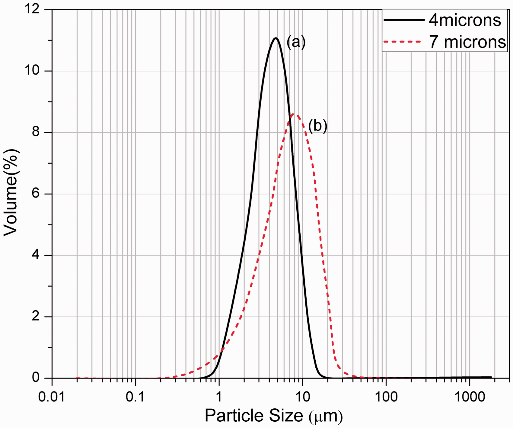
XRD patterns of starting 3Ti-Al-2 C powder mixture and reaction synthesized Ti3AlC2 powder (at 1400℃ for 60 min followed by ball milling after 8 h) are shown in Figure 1. It is evident that the powder has a Ti3AlC2 phase with a minor peak of TiC. The content of TiC was estimated by Rietveld analysis and found to be ∼10 vol.%. The mean particle sizes (d0.5) of the reaction synthesized powder after ball milling for 24 h, and 8 h were measured to be ∼4 and ∼7 µm, respectively, as shown in Figure 2. SEM images illustrate the surface powder morphology of ∼4 and ∼7 µm Ti3AlC2 particle sizes in Figure 3. It can be noted that, though in Figure 3(a) d0.5 indicates 4 µm, but fine particles are also noticed. This can be referred to the particle size analysis in Figure 2(a), which shows for d0.1 as 2.17 µm and d0.9 as 8.8 µm, respectively. Similarly, in Figure 3(b) d0.5 is ∼7 µm, d0.1 is ∼2.2 µm, and d0.9 is ∼15 µm as indicated in Figure 2(b). It can also be noted that the narrow particle size distribution is shown in Figure 2(a) and a moderately wide particle size distribution in Figure 2(b). This may be due to the less milling time adopted for the ∼7 µm powder (8 h) than the ∼4 µm powder (24 h). BET surface area of 4 and 7 µm powders is 15.5 and 6.351 m2/g, respectively. This can be related to the particle size of the powders, wherein finer particles having more surface area and coarse powder showing lower surface area.
XRD patterns of (a) starting 3Ti-Al-2 C powder mixture and (b) Ti3AlC2 powder reaction synthesized at 1400℃ under an argon atmosphere. TiC phase is also observed as the secondary phase. Particle size distribution plot of Ti3AlC2 powder after ball milling (a) 4 µm: 24 h and (b) 7 µm: 8 h. SEM images of Ti3AlC2 filler particle size after ball milling (a) 4 µm: 24 h and (b) 7 µm: 8 h.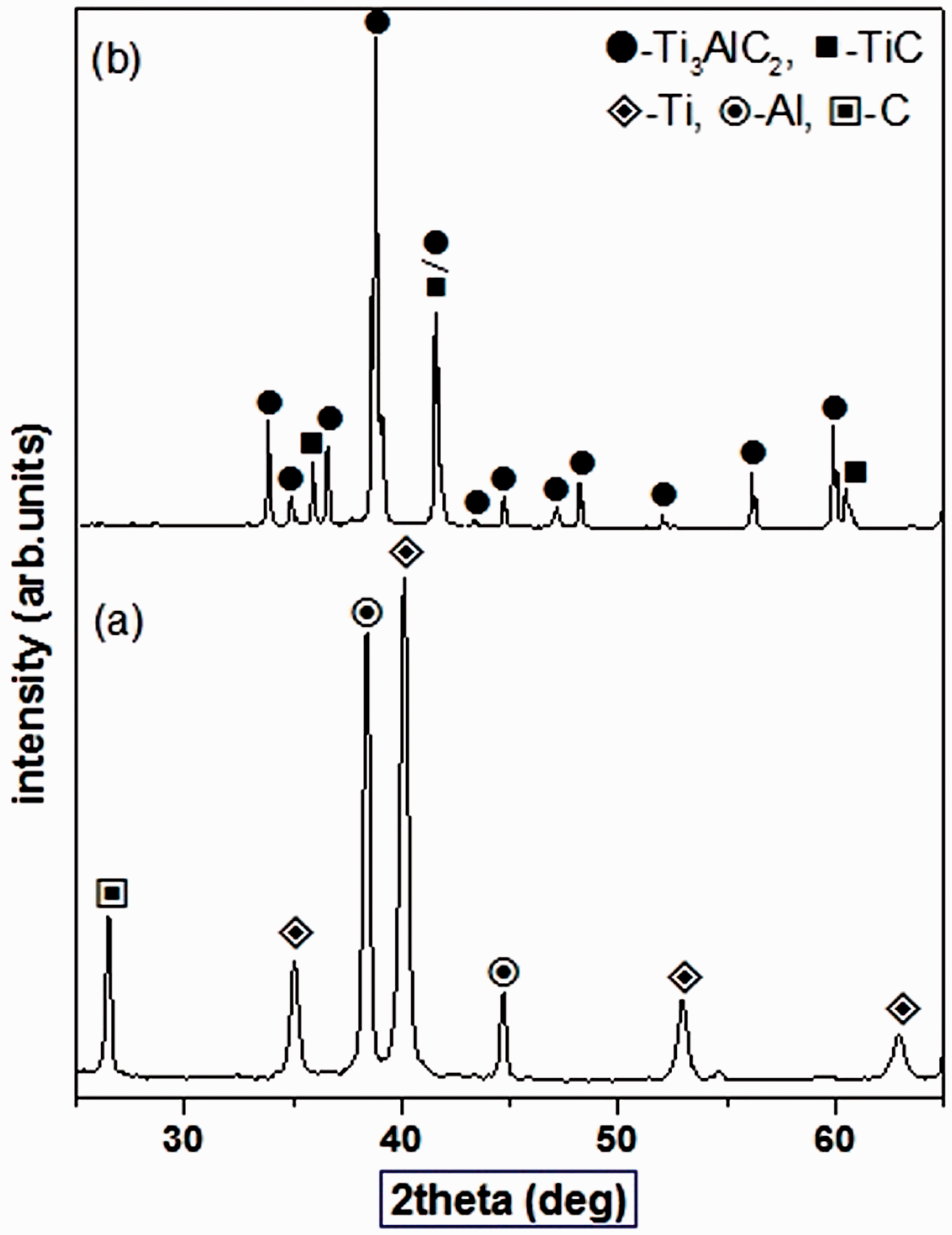

Density and microstructure of CPCs
Theoretical density, experimental density, and porosity of CPCs with different amount of Ti3AlC2 filler.

CPCs: conductive polymer composites.
SEM images of CPCs, 20 and 40 wt.% of Ti3AlC2 with 4 and 7 µm particle sizes are presented in Figure 4. The dark region is a matrix, and the light particles are Ti3AlC2. As it can be seen that the distribution of Ti3AlC2 particles appears to be homogeneous, some agglomerations are also noticed in composite with 4 µm particle size (refer to Figure 4(a) and (b)). The agglomeration may be related to the reduction in density and increase in porosity with the 4 µm particle size (Table 1). More or less homogeneous distribution of fillers is seen in the case of 7 µm particle size (refer to Figure 4(c) and (d)). A continuous network of filler particles was formed due to proper sonication of Ti3AlC2, which had resulted in the uniform dispersion of the fillers.
SEM images of CPCs with Ti3AlC2 filler with 20 wt.% and 40 wt.% of 4 µm (a, b) and 7 µm (c, d) particle size.
Mechanical properties of CPCs
Tensile and flexural properties of CPCs with different amount of Ti3AlC2 filler.

CPCs: conductive polymer composites.
The flexural strength of neat resin was 85 MPa, and with the addition of 4 µm particle filler, it was increased from 110 to 112 MPa for 10 to 30 wt.% of Ti3AlC2 (Table 2). Further, it could be noted that the strength got decreased to 86 MPa with 40 wt.%. In contrast, the addition of 7 µm filler increased the strength from 85 to 122 MPa with 10 to 40 wt.%. The flexural modulus of CPCs with 4 µm particles went up to 4.26 GPa with 40 wt.% as compared to the neat resin (3.33 GPa). Similarly, the 7 µm sized filler increased the flexural modulus to 4.28 GPa up to 30 wt.%, and further addition of filler content 40 wt.% reduced the modulus to 3.6 GPa. The Poison’s ratio of the CPCs was measured to be in the range from 0.3 to 0.4, which is equivalent to metals (Table 2), whereas the neat resin found to be 0.36.
Fractured surface analysis of CPCs
The fractured surfaces of CPCs, tested in tensile and flexural were examined in detail under SEM, which are shown in Figures 5 and 6. Figure 5(a) and (b) exhibits 20 wt.% Ti3AlC2 and (c) and (d) for 40 wt.% Ti3AlC2 with the particle size of 4 and 7 µm, respectively. Similarly, Figure 6(a) and (b) exhibits 20 wt.% Ti3AlC2 and (c) and (d) for 40 wt.% Ti3AlC2 with the particle size of 4 and 7 µm, respectively. It can be noted from Figures 5 and 6 that the surface was free from processing defects like cavities, pits, and air traps, supporting the fact that Ti3AlC2 was uniformly dispersed in the composites. It was reported in an earlier study that the surface modification of Ti3SiC234 is required to get good interface bonding between epoxy and filler. The presence of Ti3AlC2 particles was seen in the vicinity of the fracture surface; these particles showed good bonding with the matrix. Further, it can be noted that for 20 wt.% of filler content, a clear and continuous conductive network was formed, which was not seen beyond this filler loading between 20 wt.% and 40 wt.%.
SEM images for fractured surfaces of tensile tested specimens with 20 and 40 wt.%: (a, b) 4 µm and (c, d) 7 µm particle size of Ti3AlC2. SEM images of fractured surfaces of tested flexural specimens with 20 and 40 wt.%: (a, b) 4 µm and (c, d) 7 µm particle size of Ti3AlC2.

Electrical properties of CPCs
Volume resistivity (ρv) of the CPCs was calculated with 4 and 7 µm filler particle sizes using the measured resistances and geometry of the samples. The obtained ρv and conductivity of CPCs for different wt.% of Ti3AlC2 by the four-probe method are presented in Table 3. Figure 7 shows the influence of particle size on ρv for different filler loading. The ρv of neat resin was 108 mΩ.cm; however, by adding a filler of 10 and 20 wt.% decreased to 145 and 117 mΩ.cm, respectively, with 4 µm particle size. It can be noted that the decreasing and increasing trend of ρv with respect to the filler loading is shown in Table 3 and Figure 7. A similar trend was observed with 7 µm particle size, where the ρv was decreased to 228 and 170 mΩ.cm for 10 to 20 wt.% filler loading. Further, it can also be noted that the beyond 20 wt.% of filler content ρv reduced to 202 mΩ.cm. From this study, it can be understood that ρv decreased when the filler particle size was reduced from 7 to 4 µm for all the filler content loadings. However, ρv is critical with 20 wt.% filler content for both 4 and 7 µm particles sizes and the values are 117 and 175 mΩ.cm, respectively, as shown in Figure 7.
Volume resistivity vs. the different amount of Ti3AlC2 filler for 4 µm and 7 µm. Volume resistivity and conductivity of 0 to 40 wt.% Ti3AlC2 filler content. Wang et al.
33
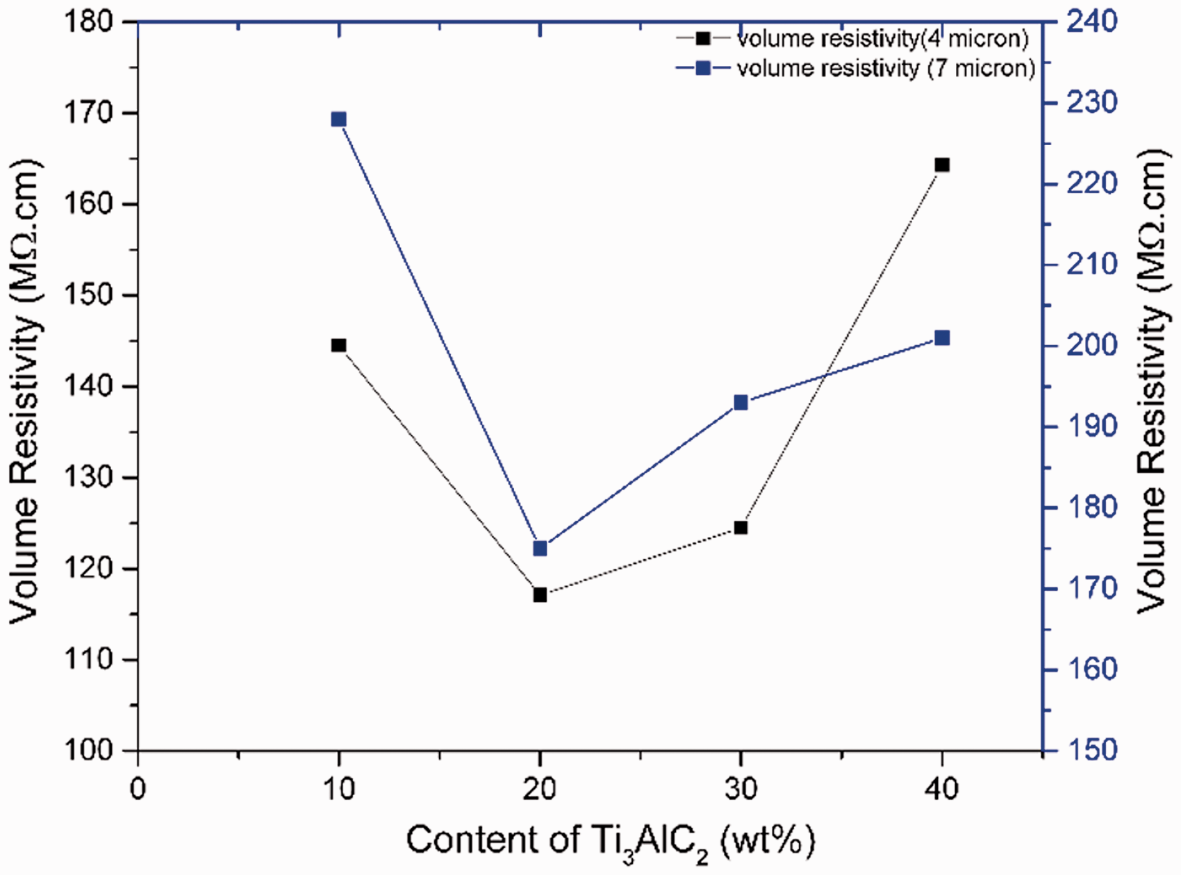

The conductivities of the CPCs with an optimized filler content of 20 wt.% for 4 and 7 µm particle sizes are 8.53 × 10⁻⁹ and 5.71 × 10⁻⁹, respectively (Table 3). This indicates that the filler was adequately dispersed and attained the percolation characteristics. The increasing conductivity trend with decreasing particle size was noticed. In fact, around ∼50% increase in conductivity (20 wt.%) was observed with 4 µm particle size compared to 7 µm.
Dielectric properties of CPCs
The dielectric properties of CPCs for various amounts of filler loadings are depicted in Figure 8 for 4 and 7 µm particle sizes, respectively. The dielectric properties of CPCs increased with respect to the increase in filler loading. The values of dielectric constant (ɛ) and dielectric loss in the frequency range of 100 Hz to 1 MHz (102 to 106 Hz) with 4 and 7 µm particles were measured and are given in Tables 4 and 5, respectively. The ɛ of neat resin was 4.09 at 1 kHz, and it increased to 4.31 at 20 wt. % for 4 µm particle size (Table 4 and Figure 8(a). Further, it can be noted that there was a reduction of ɛ with 30 wt.% filler, while 40 wt.% maintained almost similar to that of neat resin. As the frequency increased, the ɛ got reduced, which is evident from Table 4. The improvement of ɛ was found with the 7 µm particle size filler (Table 5 and Figure 8(b). The ɛ value for the optimum filler loading (20 wt.%) was 7.11 at 1 kHz; however, it was decreased to 6.70 at 106 Hz. It is worth noticing that the critical filler content is 20 wt.% for both particle sizes (4 and 7 µm).
Dielectric properties as a function of Ti3AlC2 content for 4 and 7 µm; (a) and (c) at 1 kHz and (b) and (d) at 1 MHz. Dielectric constant and dielectric loss of CPCs as a function of frequency (Hz) in 4 µm particle size of Ti3AlC2. CPCs: conductive polymer composites. Dielectric constant and dielectric loss of CPCs as a function of frequency (Hz) in 7 µm particle size of Ti3AlC2. CPCs: conductive polymer composites.


The dielectric loss values for the 4 and 7 µm filler particle sizes are 0.009 and 0.006 in 1 kHz bandwidth (Tables 4 and 5). Further, in the 1 MHz frequency bandwidth, the dielectric values increased significantly for the 7 µm filler particle size with 20 wt.% filler content. The dielectric loss of the developed CPCs was observed to be in the range of 0.027 to 0.023, which ensures a low dielectric loss, compared to earlier works. 31 Indeed, in the 1 kHz bandwidth, the dielectric loss was minimum, regarding 1 MHz frequency bandwidth. Further, it was seen from the SEM study that up to 10 wt.%, less interaction occurred between the matrix and Ti3AlC2 filler. As the filler content was increased to 20 wt.% (Figure 4(c)), a continuous network was formed among the particles, which eventually resulted in an average polarization to improve the dielectric properties of the composites.
Figure 9 depicts the dielectric properties as a function of frequency for filler particle sizes of 4 and 7 µm. In the tested frequency range from 100 Hz to 1 MHz (102 to 106 Hz), it was evident that the dielectric constant appeared to be independent of the frequency for a given wt.% of filler content. Also, the increase in filler wt.% contributed to enhancing the dielectric capacity of CPCs. In contrast, the dielectric loss was noticed to be sensitive to frequency as well as variation in filler content, and it also depended on Ti3AlC2 particle size.
Dielectric constant and dielectric loss as a function of frequency (0 to 40 wt.%) filler of particle sizes of 7 µm (a) and (c) and 4 µm (b) and (d).
Discussion
Ti3AlC2 powder and CPCs
From the XRD results, it can be seen that the secondary phase TiC was present with the reaction synthesized Ti3AlC2 powder (Figure 1). It is also evident from the literature that TiC can be used as conductive filler28,29 into CPCs. Therefore, the presence of TiC in the current study is expected to contribute towards the improvement in both mechanical and electrical properties of CPCs. The particle sizes obtained in the present work are finer than that of reported in the literature. 33 It can be noted that increasing the milling time from 8 to 24 h reduced the particle size from 7 to 4 µm (Figure 2). As it is known that the Ti3AlC2 phase is ductile, therefore a reduction in particle size was marginal with respect to increased milling time.
The density of CPCs with optimum filler content (20 wt.%) for 4 and 7 µm particle sizes is almost similar. Interestingly, the porosity of the CPCs is high with 4 µm for the optimized 20 wt.% filler content. Since it is known that, as the critical content of filler overtakes, the remanence of porosity within the solid particles is due to non-wetting/flowing of epoxy.
Effect of Ti3AlC2 on mechanical properties
The extensive characterization of mechanical properties illustrated that the tensile strength (53%), tensile modulus (35%), flexural strength (19%), and flexural modulus (14%) were increased with 4 µm filler size, compared to the neat resin (Table 2). Also, the tensile modulus and flexural strength CPC increased in 4 µm than 7 µm particle size. The tensile property and flexural strength increased while the particle size decreasing due to better dispersion of finer particles and high surface area.40,41 It is interesting to refer Wang et al., 33 who studied the influence of different wt.% of the filler (18 µm sized) and concluded 40 wt.% as critical content. However, in the present study, a novel feature was brought out in the Ti3AlC2-based CPC, wherein the critical filler content was found to be 20 wt.%. It can be seen that the reduction in filler particle size effectively reduced the percentage of filler loadings, which required to develop high-performance CPCs using epoxy. The flexural modulus and strength of the CPC in the reported literature 33 were 3.02 GPa and 62.5 MPa, respectively. In the present study, the modulus for 4 and 7 µm particle sizes shown increased 3.88 GPa and 3.72 GPa, compared to the neat resin (2.33 GPa). The flexural strength was also found to be higher with 20 wt.% critical content (Table 2), which indicated the negligible amount of porosity in the composite; however, in the earlier study, the density value of CPC was not reported. 33 The current research substantially demonstrated that 20 wt.% filler loading provides better mechanical properties with lower density as required for aerospace and strategic applications. Furthermore, mechanical properties of the CPCs could be tailored based on interfacial cohesion (compatibility) between the matrix and reinforcement. For the filler content up to 20 wt.%, the particles were homogeneously distributed in the matrix; above 20 wt.%, agglomerations of fillers were observed, which deteriorated the mechanical properties. The agglomeration of fillers acted as individual clusters, consisting of porosity, led to a reduction in mechanical properties (Table 2). The remarkable change in tensile properties of CPCs, compared to neat resin indicated that both filler particle size and the amount of particle loading played a vital role. It can be noticed that the filler with higher surface area creates more porosity (Table 2) in the composites, leading to reduction in strength.
The tensile modulus of 20 wt.% CPC increased by approximately 35%, compared to the neat resin and this trend was observed for both 4 and 7 µm particle sizes, respectively. Irrespective of the filler content (0 to 40 wt.%), the filler particle size showed a significant role in increasing the tensile modulus. A similar trend was also noticed for tensile modulus. However, the maximum tensile modulus (3.60 GPa) and strength (58.6 MPa) were obtained for 4 µm filler size with 20 wt.% content. A mixed trend was seen for the tensile properties, with respect to different wt.% of filler loading and particle size. 42 Unlike the brittle ceramic fillers (SiC, Al2O3, TiC, etc.), the presence of Ti3AlC2 introduced the metalloid like behavior in the CPC, till the percolation threshold. 42
Validation of tensile properties with analytical results
The experimentally measured tensile properties of CPCs with 4 and 7 µm filler sizes and 0 to 40 wt.% are compared with the theoretically obtained values from Einstein (with and without adhesion), Kerner, Sato-Furakowa equations. 43 These models (1 to 4) are briefly explained below for the sake of completeness.
The Einstein equation (without adhesion parameter) is defined as


The Kerner model considers Poison’s ratio of the matrix while calculating the tensile properties of the composites as

Sato and Furukawa have developed equations (4) and (5) for computing the modulus with adhesion as parameter


In the above equations (1) to (5), the following notations are used;
Mc – Modulus of the composite, Mm – Modulus of the matrix, V1 – Volume fraction of the filler, Vm – Volume fraction of the matrix, r – Poison’s ratio of the matrix, j – adhesion parameter.
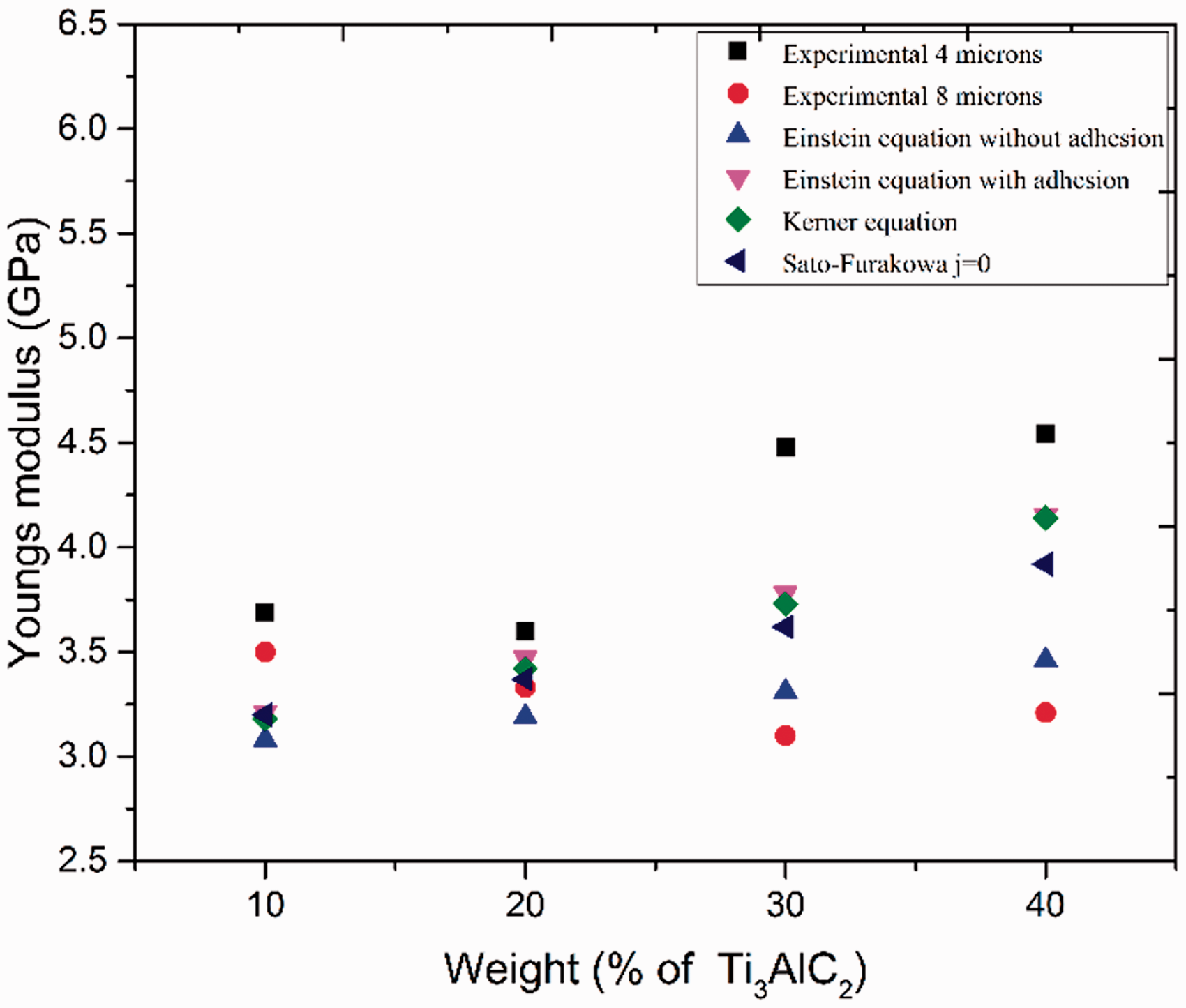
Young’s modulus obtained from the experiment for different filler loadings and two filler sizes along with their theoretical values is shown in Figure 10. The effect of filler particle size is found to be significant, which has increased the modulus of the neat resin from 2.33 to 4.54 GPa at 40 wt.% filler loading. Both filler particle size and its wt.% loading have introduced a non-linear elastic nature into CPCs, which is visible in the observations. The analytical models (1 to 4) are linear and do not consider the filler particle size while computing the tensile modulus. In the case of 20 wt.% filler content, the experimental and all theoretical values are converged (Figure 10). It substantiates the fact that 20 wt.% filler content is critical, in which the particles are homogenously dispersed. Thus, one can see a lot of variation in the analytical predictions. However, the predicted values are found to be in the same range as in the experiments. The tensile strength of CPC may be computed using the model as given in equation (6)
Tensile modulus vs. filler content with the theoretical model's prediction for 4 and 7 µm filler size.
The tensile strength of the CPCs, along with the theoretical predictions, for both particle sizes is presented in Figure 11. It can be noticed that, up to the critical filler loading (20 wt.%), an increasing trend in the tensile strength is seen with decreasing particle size. However, for 30 and 40 wt.%, a mixed trend is observed, possibly due to the agglomeration effect. As discussed earlier, the presence of porosity is the main contributor to the reduction of mechanical properties (Table 1).
Tensile strength vs. filler content with the theoretical model prediction for 4 and 7 µm filler size.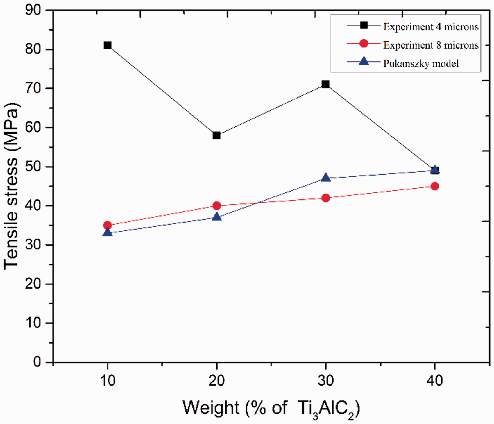
Conductivity and dielectric behavior
The presence of a small amount of TiC in Ti3AlC2 powder may maintain the similar dielectric constant in CPCs. With reference to the earlier study, 29 it can be noted that an addition of monolithic TiC to epoxy resin increases the conductivity. The dielectric loss of CPCs, observed to be 91–94% in the present study, is much lower compared to the reported values in the literature. 33 Using 4 and 7 µm particle sized fillers, dielectric properties of CPCs were very significantly enhanced by adding them in lower weight percentage (20 wt.%), when compared to the reported study in the literature. 33 The dispersion of optimized filler content without agglomeration is the main criteria to attain better conductivity and low dielectric loss. The point to be noted is that the current study does not consider any polyamide as a curing agent. Moreover, the properties of CPCs can be tailored using appropriate wt.%, either to optimize the mechanical or the electrical properties by varying the filler content from 20 to 30 wt.%, accompanied by lower filler particle size.
To summarize, it is demonstrated that 20 to 30 wt.% Ti3AlC2 range appears to be the optimum filler content to develop aircraft grade epoxy-based CPCs for high-performance engineering applications with enhanced dielectric properties and mechanical characteristics, without contributing much to the weight.
Conclusions
The study on the processing of aircraft grade epoxy-Ti3AlC2 composites led to the following conclusions:
Reaction synthesized Ti3AlC2 powder was used to produce epoxy-based CPC with 10 to 40 wt.%. Nearly dense CPC could be produced with 20 wt.% filler content. Particle size was found playing a crucial role in mechanical, electrical and dielectric properties of the CPC composites. Experimentally measured tensile properties were found to be in good agreement with those values predicted by various analytical methods. The aircraft qualified non-conductive epoxy was upgraded to high-performance CPC, using optimal sized Ti3AlC2 particles and filler loading. First time, the influence of Ti3AlC2 reinforcement in epoxy (DGEBA) was evaluated to address the tensile, flexural properties of the composite. A very significant increase in the electrical resistivity (78%) was observed with developed Ti3AlC2 based-CPC in the current research, compared to the earlier study.
33
Footnotes
Acknowledgment
The authors are indebted to Mr. K Rajaguru for powder preparation, Dr. Anjana Jain for recording XRD patterns, Dr. Abanti Nag for resistivity measurement, Mrs. Kalavati for SEM work and Mr Mariappan L for surface area measurement. Thanks are due to Mr. Jaganathan, Mr. Jerald Mario Anthony and Mr. Mahesh for their contributions in testing activities.
Declaration of Conflicting Interests
The author(s) declared no potential conflicts of interest with respect to the research, authorship, and/or publication of this article.
Funding
The author(s) disclosed receipt of the following financial support for the research, authorship, and/or publication of this article: This work was enabled by the financial support from ASTA, CSIR-12th FYP (ESC-0212/02).