
Abstract
The paper aims to explore potential higher value applications of discontinuous carbon fibre tows. A vibration-assisted dry alignment method is presented to align the discontinuous fibre tows between conventional dry reinforcement mats/fabrics to fabricate cost-effective hybrid composites. Its viability is demonstrated by successful fabrication of two hybrid composite panels, where thin layers of aligned 12 mm discontinuous carbon fibre tows were deposited between E-glass chopped strand mats or woven fabrics respectively, via an out-of-autoclave resin infusion process; 54% and 81% of the fibre tows were aligned in the range of ±5° and ±10°, respectively. The tensile test results clearly demonstrate the importance of having the discontinuous fibre tows highly aligned in the hybrid composites, which shows increased stiffness (up to 24.4%) and strength (up to 59.9%) over the non-aligned hybrid composites. The aligned hybrid composites also exhibit a non-linear pseudo-ductile response due to subcritical progressive damage compared to the catastrophic brittle failure of the baseline non-hybrid E-glass and non-aligned hybrid composites, despite the tensile strength knockdown (up to −40.3%) due to premature inter-tow debonding. They also display increased stiffness up to 90%.
Introduction
Discontinuous fibre tows can be processed either from expired or scrapped continuous tows. Composites made from discontinuous fibres are known to offer good compliance and formability. They exhibit similar stiffness to that of quasi-isotropic laminates, are insensitive to holes and defects, and are more damage tolerant.1–3 However, their low strength and high material variability inhibit their uptake in load-bearing applications. They typically end up as low-value reinforcement in randomly orientated preforms for bulk moulding compounds, coatings and cavity filling. Composites made from discontinuous fibre preforms currently face a few limitations: (1) Large-scale application has been restricted by the costly and time-consuming fibre preforming stage before they are liquid-moulded, (2) the fibres are in a random 3D orientation which implies their potential as reinforcement is not fully achieved and it is hard to tailor their mechanical properties, and (3) the randomly orientated fibre preforms are usually thick due to high preform loft and low fibre volume fraction, which imposes constraints on the component design.
In contrast to the expensive continuous fibre composite prepregs, discontinuous carbon tows are convenient to distribute in smaller quantities and do not require sophisticated transport, storage and manufacturing facilities which are not commonly accessible. This paper sets out to explore potential higher value applications of discontinuous carbon tows as one of the constituent materials in cost-effective hybrid composites, with the ultimate goal to encourage uptake of composites for semi-structural applications. This is of particular interest for automotive components which are typically driven by stiffness and damage tolerance rather than strength. Hybrid composites in general refer to composites which have a combination of two or more reinforcement fibres. The purpose of hybridisation is to achieve a composite architecture which offers improved mechanical properties via synergistic effects between the constituent fibres and/or to lower the cost by partially replacing the expensive fibres with the cheaper ones. As a trade-off solution for formability and mechanical performance, discontinuous fibres have commonly been hybridised with continuous fibres to make them suitable for structural applications.4–7 For optimal mechanical performance, the requirement to have significant levels of alignment in the discontinuous fibre layers within a hybrid composite is apparent.
An overview of the history of aligned short fibre composites has been discussed by Such et al. 8 Most of the alignment processes for short fibres reported in the literature used wet hydrodynamic techniques, in which discontinuous fibre filaments were dispersed and suspended in a high viscosity liquid medium such as glycerol9,10 or in low viscosity water 11 before it was pumped through a nozzle. The fibres can then be aligned following the high fluid velocity gradient at the nozzle9,10 or via momentum change after the fibre suspension is discharged onto parallel plates. 11 The major drawback of hydrodynamic methods is that a very dilute suspension of short fibres (0.003–0.5% volume fraction) is required for minimising fibre interaction and flocculation, which compels a fluid removal process via vacuum or heating before the preform can be processed further.
Hydrodynamic techniques are not suitable for aligning discontinuous fibre tows, where thousands of individual filaments are held together in bundles and they are typically long (more than 10 mm). A dry alignment method is therefore more applicable in order to maintain the straightness and stiffness of the long fibre tows for ease of handling. A dry pneumatic alignment method was used by Ericson and Berglund 12 to align glass-mat-reinforced thermoplastics by blowing a mixture of 25 mm long glass fibre bundles and thermoplastic powder through two horizontal orientation plates onto a perforated steel sheet. Low level of alignment was achieved where the fibres were evenly distributed between effective angles ±52° due to fibre bundle disintegration during the preforming step. Harper et al. 13 incorporated a nozzle-like alignment concentrator within their directed carbon fibre preforming process, which sprayed aligned carbon fibre bundles and polymeric binder powder onto a perforated plate. Up to 94% of the fibre bundles can be aligned within ±10° depending on the tow size and fibre length. Despite the high production rate of 0.15 kg/min, only 32.6% of the fibres were aligned within ±10° for small tow sizes (6 K) and short fibre lengths (28 mm) as they were more susceptible to disturbance during the deposition stage due to their low mass. The dry alignment techniques reported in the literature often require a vacuum capability to hold the deposited fibres in place before they could be preformed, which added complexity to the manufacturing process.
In this paper, a simple technique for aligning discontinuous fibre tows via a dry, cost effective and high productivity procedure is presented and described. It offers a high yield rate as multiple fibre tows can be aligned simultaneously over a large area. The alignment process is carried out without a liquid medium and therefore eliminates the need for a complex vacuum or heating system for liquid removal. Its feasibility is demonstrated by the fabrication of two hybrid composite panels, where highly aligned 12 mm long discontinuous carbon fibre tows are directly deposited between two different types of dry E-glass reinforcement on a tool plate and cured via an out-of-autoclave resin infusion process. The out-of-autoclave resin infusion curing process, which avoids the application of heat, helps to address the out-of-plane warping issues 2 typically seen in oven- or autoclave-cured discontinuous fibre composites due to the heterogeneity and variability of thermal expansion coefficient throughout the laminates. Tensile testing is then carried out to investigate the influence of the aligned discontinuous carbon fibre tows on the tensile behaviour of the hybrid composites. The results are compared against the tensile responses of the baseline non-hybrid E-glass composites and the non-aligned hybrid composites with randomly oriented fibre tow arrangement. The importance of having the discontinuous carbon fibre tows highly aligned in the hybrid composites is demonstrated. Compromises in the mechanical properties of the hybrid composites are discussed and potential improvements are suggested.
Hybrid composites fabrication
Carbon fibre tows
The discontinuous carbon fibre tows used in this study are Carbiso CT SM45D supplied by ELG Carbon Fibre Ltd.
14
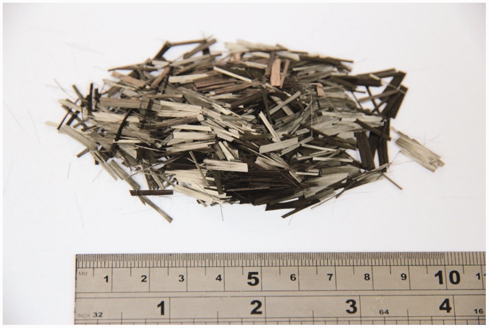
Their material data are summarised in Table 1. They have been processed originally from 50 K virgin tows with a sizing content of < 1.5%. Most of the fibre tows are already filamentised upon receipt, where the virgin tows have been reduced into a wide range of smaller bundle sizes (Figure 1).
Filamentised carbon fibre tows originated from a virgin tow size 50 K. Material data of discontinuous carbon fibre tow, Carbiso CT SM45D.
14
Dry fibre tow alignment rig design
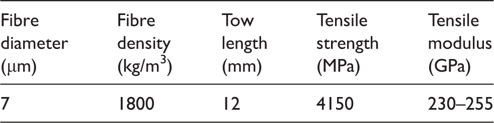
A dry fibre alignment method has been developed to align the 12 mm long discontinuous carbon fibre tows between two types of E-glass reinforcement, i.e. 300 g/m2 randomly oriented chopped strand mats (CSM) or 270 g/m2 plain weave woven fabrics (WF), respectively, to produce two hybrid composite panels. The design and assembly of the laboratory-scale dry fibre alignment set-up are shown in Figure 2(a). It mainly consists of two modules, i.e. the ‘feed module’ and the ‘alignment module’.
(a) Full assembly of the dry fibre alignment rig. Components of the ‘feed module’ are labelled in yellow, while those of the ‘alignment module’ are labelled in red; (b) A cross-sectional cut of the final stage orientation unit showing a hierarchical tree structure slit design; (c) The final stage orientation unit is assisted by two pairs of vibration motors, each driven by an independent adjustable power supply. The double-headed arrows indicate the rotation axes of the motors.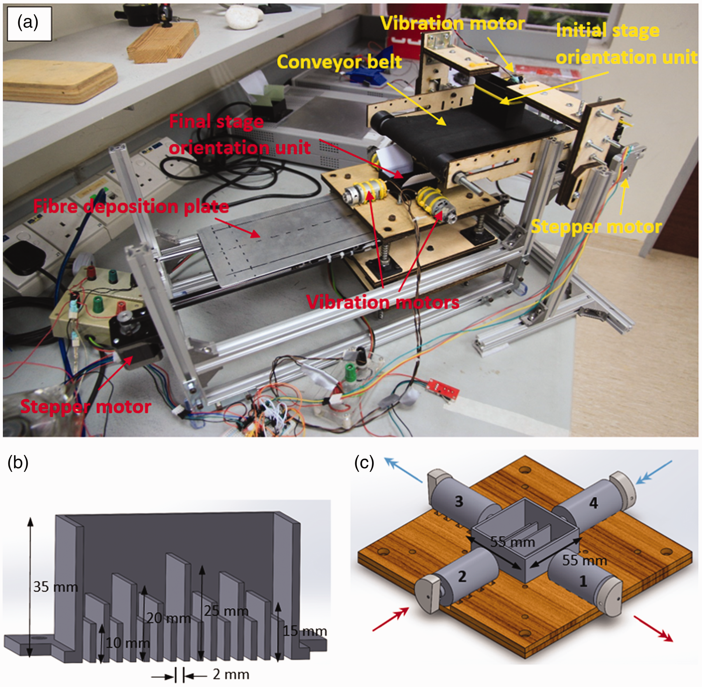
The discontinuous carbon fibre tows are firstly weighed according to the target deposition areal mass (in gram per m2 or gsm) before being fed into the initial stage orientation unit (with planar dimensions 20 mm × 55 mm) of the ‘feed module’. The orientation unit has a series of 2 mm wide slits to align and deposit the fibre tows over an area on the conveyor belt which is same in size as the target deposition area in the hybrid composite panels, assisted by a 5 V vibration DC motor to prevent fibre blockage in the orientation unit. The exit slit width of 2 mm is sufficient to accommodate the widest tow width (about 4 mm, Figure 1) used in this study by falling through at an inclined angle under the influence of vibration. The thickness of the deposited fibre tow layer on the conveyor belt is determined by the clearance distance (about 2.5 mm) between the initial stage orientation unit and the conveyor belt. The tows are aligned perpendicular to the moving direction of the conveyor belt at this stage with the purpose to prevent them overhanging collectively beyond the end of the conveyor belt and falling in a lump, which could disrupt the continuity of the alignment and deposition process (Figure 3).
(a) The initial stage fibre alignment perpendicular to the conveyor movement is necessary to avoid fibre tows overhanging the end of the conveyor belt before they fall into the final stage orientation unit. In the final alignment stage, longitudinally aligned carbon tows are deposited directly on an E-glass woven fabric. (b) A schematic diagram showing the alignment and path taken by the carbon fibre tows from the initial stage alignment to the final deposition on the E-glass woven fabric.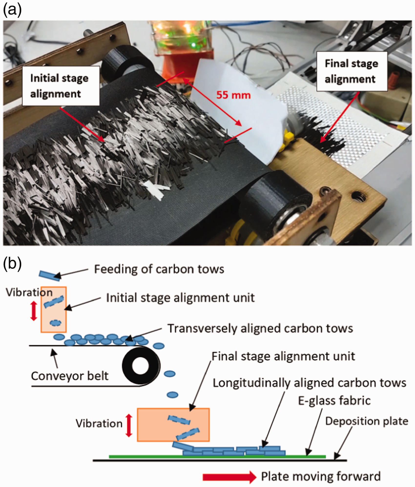
The fibre tows are conveyed to the end of the conveyor belt and dropped into the final stage orientation unit of the ‘alignment module’ which is supported on four springs. The final stage orientation unit has a length and a width of 55 mm, which is 4.5 times the length of the fibre tows, to provide sufficient room for tow rotation. The final fibre tow directionality is generated by another set of 2 mm wide slits in the final stage orientation unit, which is oriented in the longitudinal direction. The slit design features a hierarchical arrangement, similar to a tree structure, which guides the fibre tows to tilt, rotate and fall stepwise through the slits due to the uneven height of the slit walls (Figure 2(b)). The alignment is again assisted by vibration from two pairs of eccentric rotating mass DC motors (9869 r/min, 6–15 V, 7.98 W). Each pair is driven by an independent adjustable low-voltage DC power supply. The axis of rotation of each motor is illustrated in Figure 2(c) such that the overall rotational momentum is cancelled out. The voltage to the motors is varied until a vertical vibrational mode is achieved (about 3.7 V), which provides the energy to rotate the fibre tows until they fall through the slits, as well as to shake off any blocked tows between the slits. PVC pads are used to damp out the vibration at the base of the rig.
The aligned carbon fibre tows are deposited continuously on a dry E-glass CSM or WF laid on a moving aluminium deposition plate (simulating a moving tool surface) driven by a stepper motor and a toothed belt. It is important to have the lower edge of the final stage orientation unit as close as possible to the E-glass fabrics on the deposition plate in order to minimise any misalignment of the tows as they exit the orientation unit, at the same time providing sufficient clearance to allow for the build-up thickness of the aligned discontinuous tow layer and the vibrational displacement of the final stage orientation unit. A vertically adjustable support platform is therefore designed to keep the deposition plate at the appropriate clearance distance and offer the flexibility to adjust the plate position for different deposition thicknesses. The minimum clearance distance of 4 mm gives the best results for the tow deposition areal mass of 360 g/m2 used in this work. The feeding speed of the carbon tows by the conveyer belt is also another important processing parameter and it needs to be in sync with the speed by which the deposition plate moves. Too high the feeding speed will result in tow overfill and clogging in the final stage orientation unit. For the current work, the speed is set at 2.4 mm/s for optimal productivity.
The components of the alignment rig are mostly 3D-printed from ABS thermoplastic or laser-cut from plywood. All moving mechanisms are controlled using a microcontroller (Arduino UNO) and are programmed using the open-source Arduino Software.
Alignment results
The current setting of the alignment rig can reliably process carbon fibre tows at 4.5 g/s (16.2 kg/h) for a composite panel of 200 mm long and 55 mm wide. A higher deposition rate can be achieved if a wider conveyor belt and a larger orientation unit are used. An areal mass of 360 g/m2 is found necessary to minimise the appearance of open pores in the deposited layer before it becomes too thick. Figure 4 shows the alignment result after 360 g/m2 of carbon fibre tows were aligned and deposited on the E-glass CSM and WF, respectively.
360 g/m2 of aligned 12-mm-long carbon fibre tows deposited on (a) an E-glass chopped strand mat and (b) an E-glass woven fabric.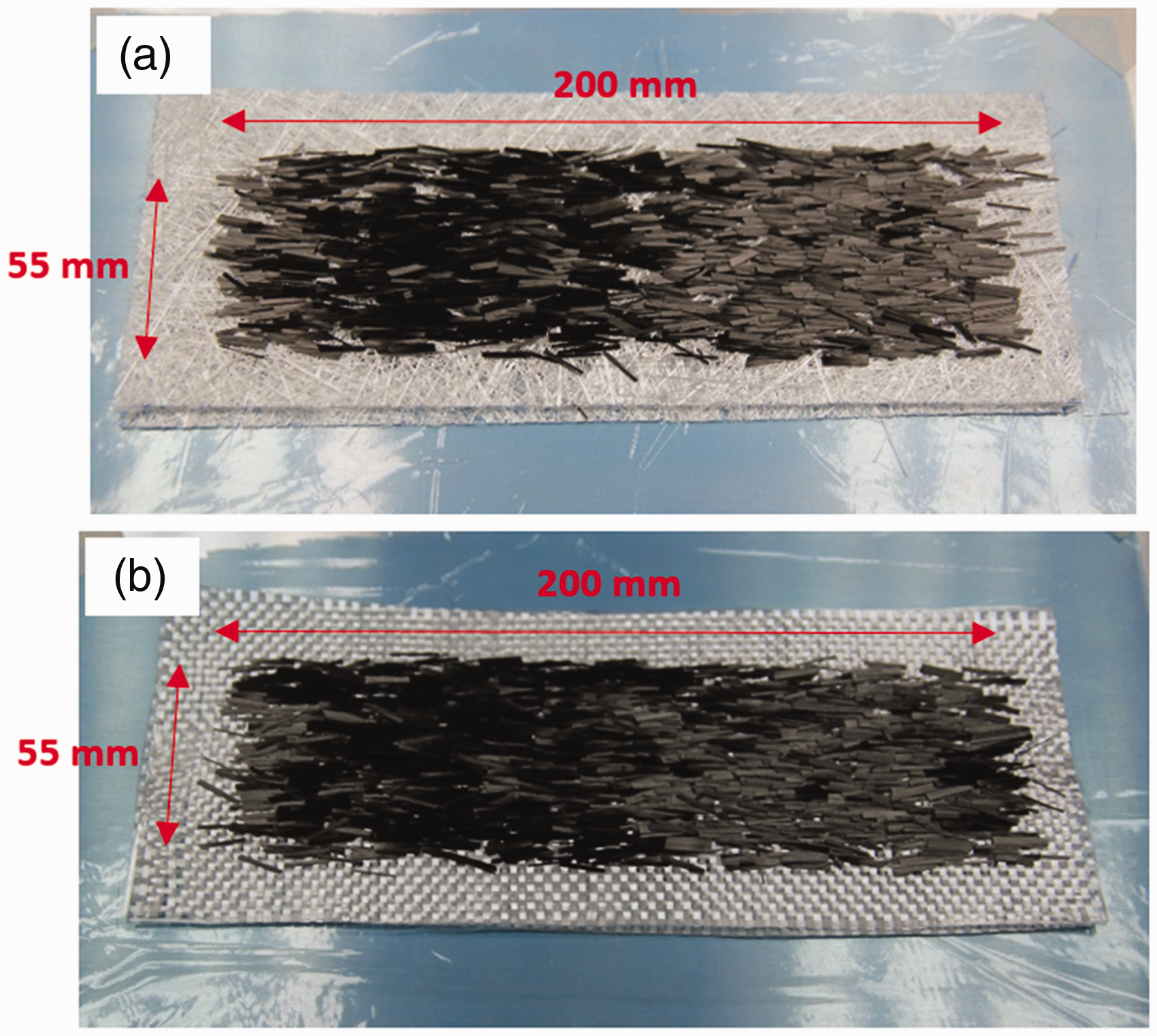
An approach similar to Harper et al. 13 and Yu et al. 11 was adopted to measure the in-plane tow orientation in order to gauge the alignment quality. A digital image of the plan view of the deposited carbon fibre tows was taken under a white light after the alignment process. The resulting image was imported into a CAD software application where straight lines were drawn manually along the edge of fibre tows in the longitudinal direction over the image. Coordinates of the starting and ending points of each line were recorded and exported as a text file which was then post-processed to determine the in-plane tow orientation.
Note that the approach described above only allows in-plane orientation measurement of the surface fibre tows. Harper et al.
13
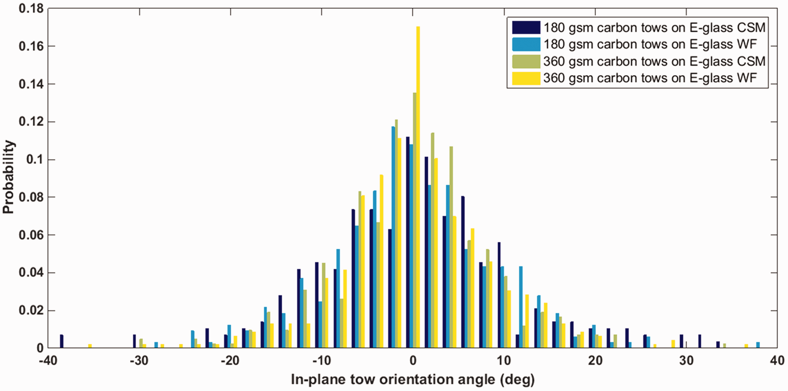
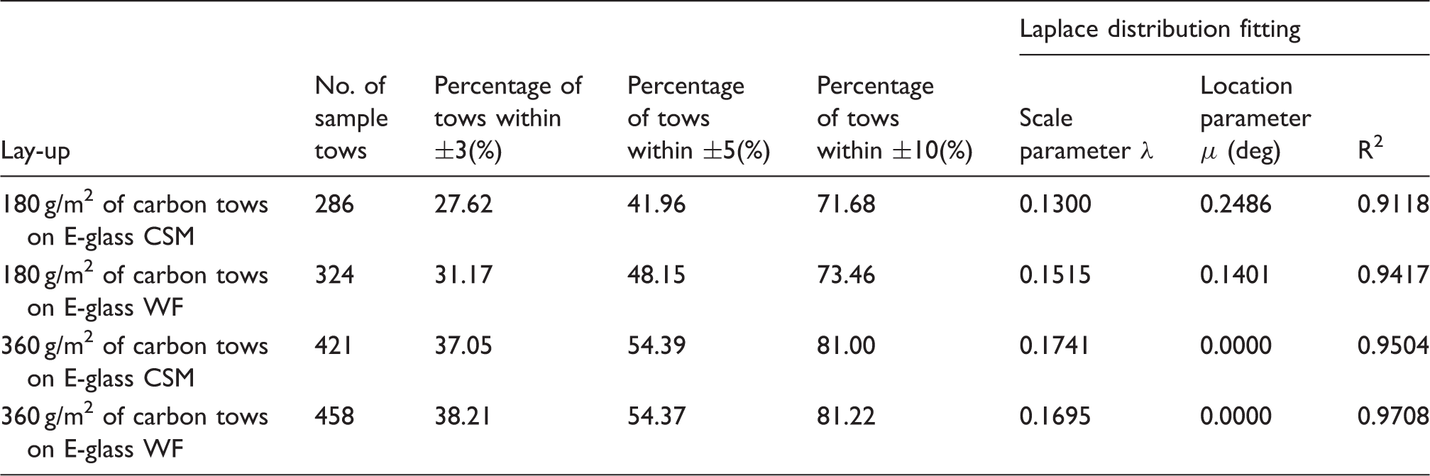
found that tow alignment tended to decrease through the thickness due to reduced vacuum capability of the tool as the preform layers were built up. In the present study, without having the aid of vacuum to hold the tows in place, it is therefore essential to inspect the discrepancy in tow alignment through the layer thickness. The tow orientation was investigated for two deposition thicknesses (i.e. 180 g/m2 and 360 g/m2 as allowed by the tight clearance distance of 4 mm between the orientation unit and the E-glass fabrics/mats), each deposited on the E-glass CSM and WF to look into the influence of deposition surface as well. The 180 g/m2 thickness represents the early stage of the deposition process where unfilled open spots are ubiquitous. The tow orientation measurements for the four cases are presented as four discrete probability density functions in a single plot for ease of comparison in Figure 5, and the results are summarised in Table 2. Around 300 to 450 discernible surface carbon fibre tows depending on the deposition thickness were sampled to assess the alignment quality. Similar to the work by Harper et al.,
13
a simple two-parameter Laplace distribution (double exponential distribution) based on the Kolmogorov–Smirnov test
15
is found to give a good fit to the distribution of tow orientation for all cases:
Probability density functions for in-plane tow orientations of four study cases, where two areal masses of carbon tows (180 g/m2 and 360 g/m2) are deposited on two reinforcement types (E-glass CSM and E-glass WF). Level of alignment of carbon tows with respect to areal weight on different deposition surfaces.
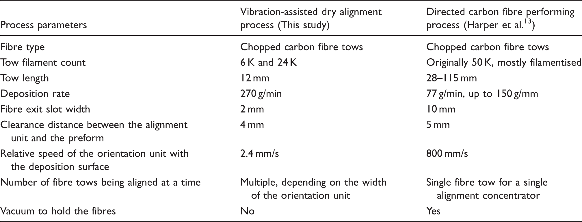
Comparison of the process parameters between the vibration-assisted dry alignment process used in this study and the directed carbon fibre performing (DCFP) process by Harper et al. 13
A maximum misalignment angle of about ±10° is geometrically permissible for a 12 mm long carbon fibre tow falling through the 2 mm slit width of the orientation unit. Both Figure 5 and Table 2 show that about 72–81% of the deposited fibre tows are within ±10° regardless of the deposition thickness. Any misalignment beyond ±10° is caused by the complex interaction among the fibre tows, or between the tows and the moving parts of the alignment rig. It could be new fibre tows sliding off previously deposited tows, or disruption of previously deposited tows by new ones exiting the vibrating orientation unit as the deposition plate travels forward. Note that tow filamentisation or splitting can take place during the alignment process. The size and stiffness of the fibre bundles can also influence the quality of fibre alignment. Higher levels of alignment can be achieved for larger bundle size as heavier tows are less susceptible to disturbances once they have been deposited. 13
Hybrid composites and specimen fabrication
Two hybrid composite panels were manufactured by embedding two thin layers of aligned discontinuous carbon fibre tows (CT) between three layers of E-glass randomly oriented CSM and E-glass plain weave WF respectively, i.e. [CSM/CT/CSM/CT/CSM] (abbreviated as hybrid CSM/CTaligned) and [WF/CT/WF/CT/WF] (abbreviated as hybrid WF/CTaligned), as illustrated in Figure 6. This minimises direct handling of the thin aligned discontinuous carbon fibre tow layers which otherwise requires the application of binder and heat treatment to set it. It also avoids direct contact between the aligned carbon tows and the smooth tool surface which could potentially lead to fibre washout and misalignment during the resin infusion process.
Stacking sequence of two hybrid composite panels made from two layers of aligned discontinuous carbon fibre tows interlaminated between three layers of (a) E-glass chopped strand mat [CSM/CT/CSM/CT/CSM] and (b) E-glass plain woven fabric [WF/CT/WF/CT/WF].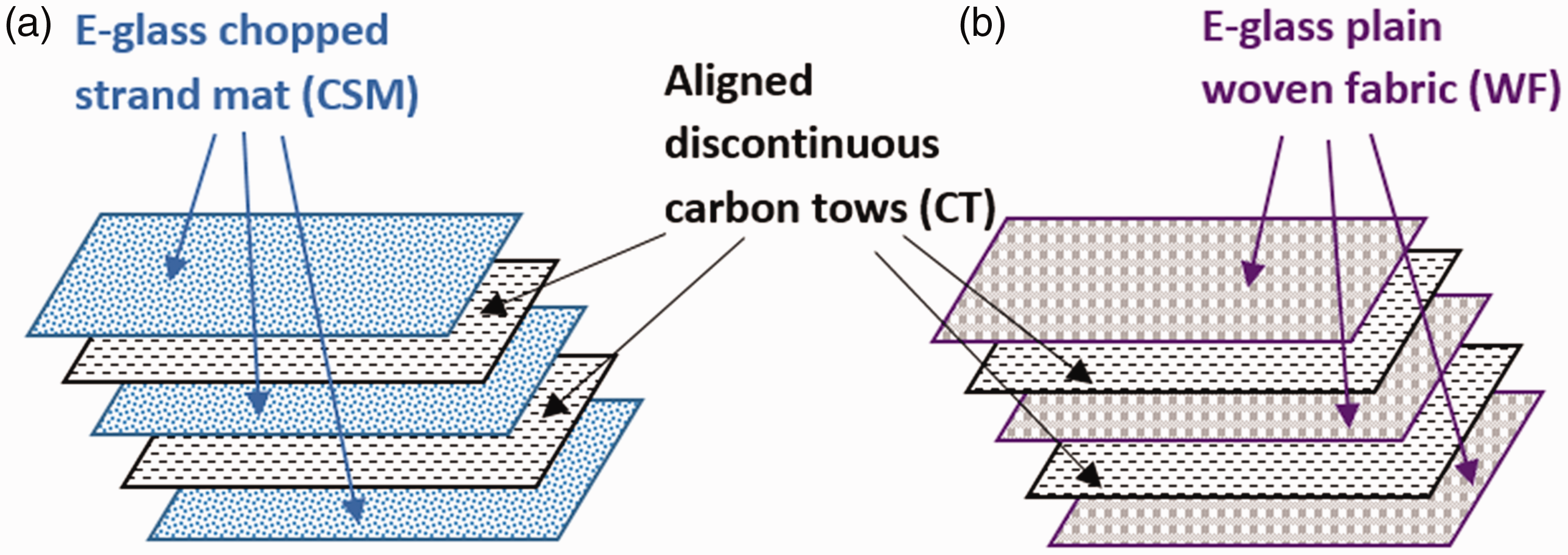
The manufacturing process of the hybrid E-glass WF/CT is depicted in Figure 7; 360 g/m2 of aligned carbon fibre tows were first deposited over an area of 200 mm long and 55 mm wide directly on an E-glass WF (240 mm long and 95 mm wide) placed on the deposition plate in the fibre alignment rig. After the deposition was completed, the lay-up ([CT/WF]) was carefully transferred to a tool plate, before a second identical lay-up ([CT/WF]) and a final E-glass woven fabric ([WF]) were stacked on top of it. The full lay-up ([WF/CT/WF/CT/WF]) was subsequently consolidated in a vacuum bag, which also held the aligned carbon fibre tows firmly between the woven fabrics under atmospheric pressure, before it was infused with epoxy resin (EpoxAmite 100) flowing in the direction parallel to the aligned fibre tows. No tow movement or washout due to resin flow was observed through the translucent surface of the E-glass fabric. After the laminate was cured at room temperature for 24 h, 20 mm of its edges were trimmed off using a water-cooled diamond wheel cutter. The same fabrication process was repeated for the hybrid E-glass CSM/CT laminate. The obtained hybrid laminates showed a smooth surface on the mould side but a wavy surface on the bagging side due to tow overlaps and gaps, similar to the aligned carbon fibre tow specimens manufactured by Oliveux et al.
16
To allow benchmarking, two baseline non-hybrid laminates consisting of three layers of E-glass CSM and three layers of E-glass plain weave WF, respectively, and two hybrid laminates having the same constituent materials and layup as used for the aligned hybrid composites but with non-aligned carbon fibre tows replacing the aligned carbon tows (i.e. CSM/CTrandom and WF/CTrandom) were also fabricated. In the CSM/CTrandom and WF/CTrandom laminates, the random carbon fibre tows were deposited manually with the same areal thickness as in the CSM/CTaligned and WF/CTaligned laminates. Following the same procedures described in ‘Alignment results’ section, the orientation of the random carbon fibre tows was checked to ensure they were evenly distributed in all directions.
Manufacturing process of the hybrid composite panels for tensile test.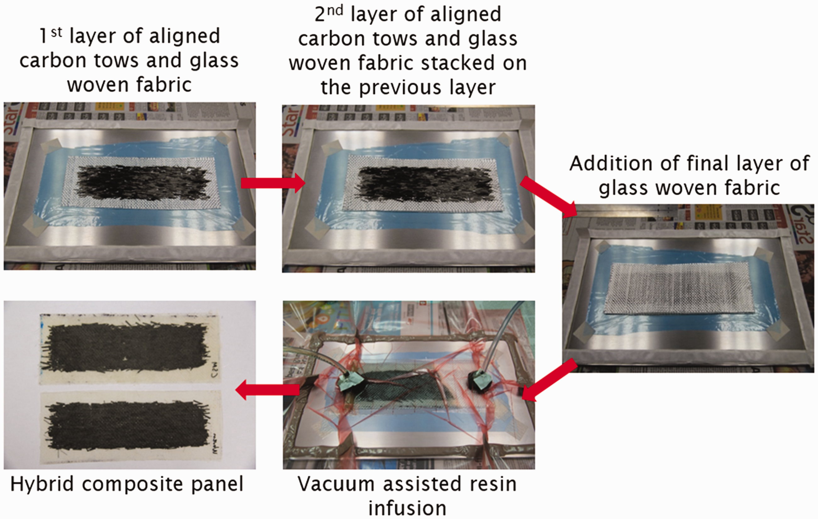
Tensile test results of non-hybrid E-glass laminates compared to their hybrid laminates with random and aligned carbon tows.
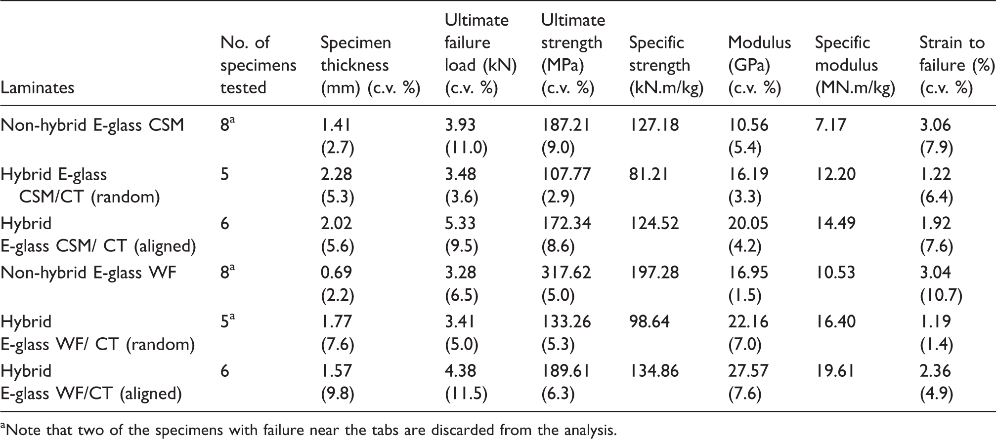
Note that two of the specimens with failure near the tabs are discarded from the analysis.
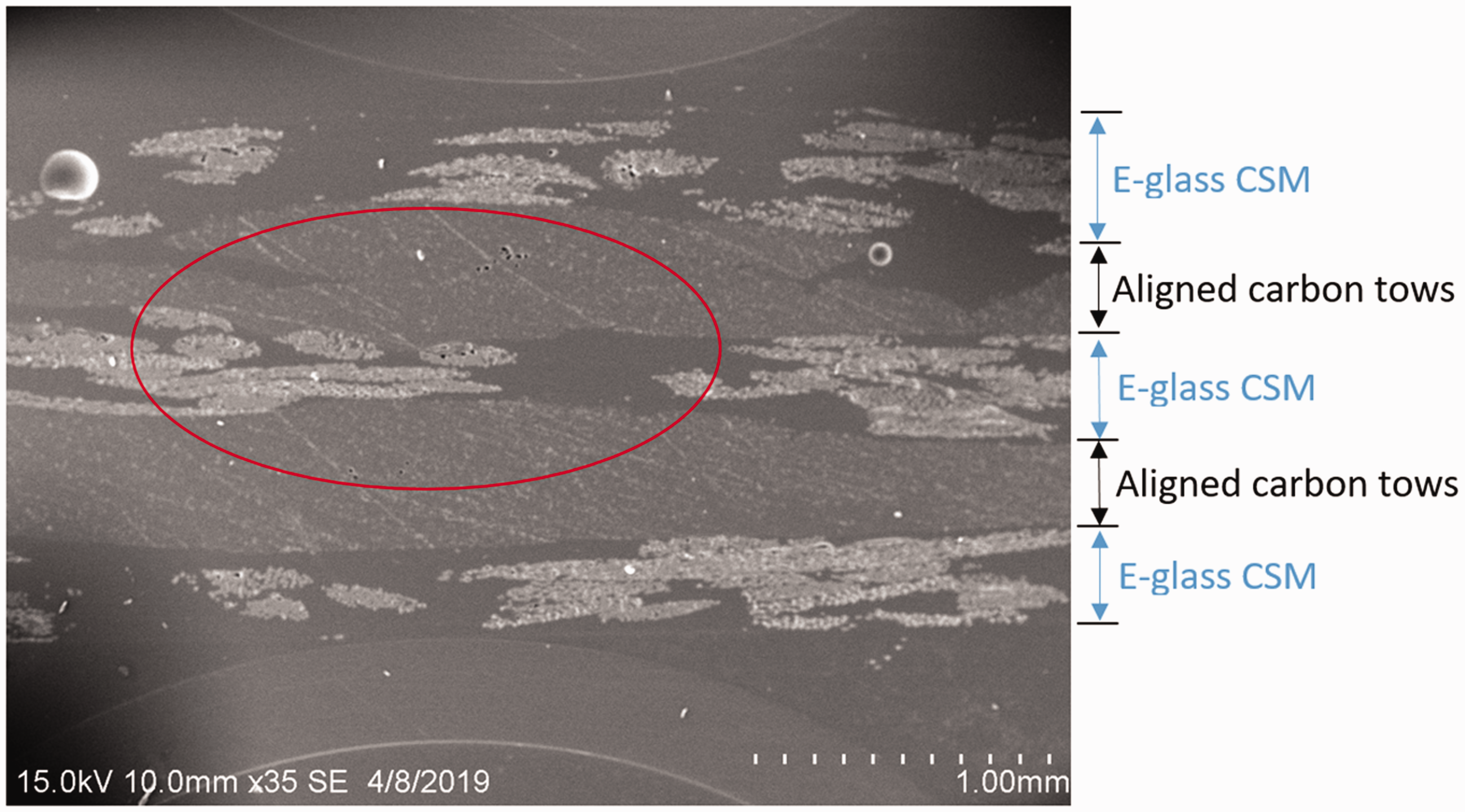
The introduction of carbon fibre tows in the hybrid laminates generally increases the variability of the laminate thickness, as indicated by the coefficient of variation (c.v.) of the specimen thickness in Table 4, particularly for the hybrid E-glass WF/CT laminates. The variation in thickness is inevitably resulted from the gap and overlap ‘defects’ in the non-homogeneous discontinuous carbon tow layers, as shown in Figure 8. Other microstructural features such as tow waviness and crimp of the E-glass woven fabric can also be clearly seen. In the aligned hybrid laminates, despite the same amount of aligned carbon fibre tows were deposited, the apparent thickness of a single aligned carbon fibre tow layer in the hybrid E-glass CSM/CTaligned laminate was found to be thinner, i.e. 0.30 mm, compared to 0.44 mm in the hybrid E-glass WF/CTaligned laminate. The same observation can also be made between the hybrid E-glass CSM/CTrandom and WF/CTrandom laminate. The difference can be explained by the high degree of preform loft in the CSM which allows nesting of short carbon tows within the interstitial space of its random fibre arrangement (Figure 9), whereas this is not permissible in the structurally compact woven fibre architecture.
Micrograph showing microstructural features of (a) hybrid E-glass CSM/CT and (b) hybrid E-glass WF/CT laminates. Scanning electron microscopic (SEM) image of a cross-sectional area of a hybrid E-glass CSM/CTaligned laminate showing penetration (nesting) of the aligned carbon tows into the interstitial space of the randomly orientated E-glass CSM layer, highlighted in the circle. Note that the aligned carbon fibres are orientated out of the image.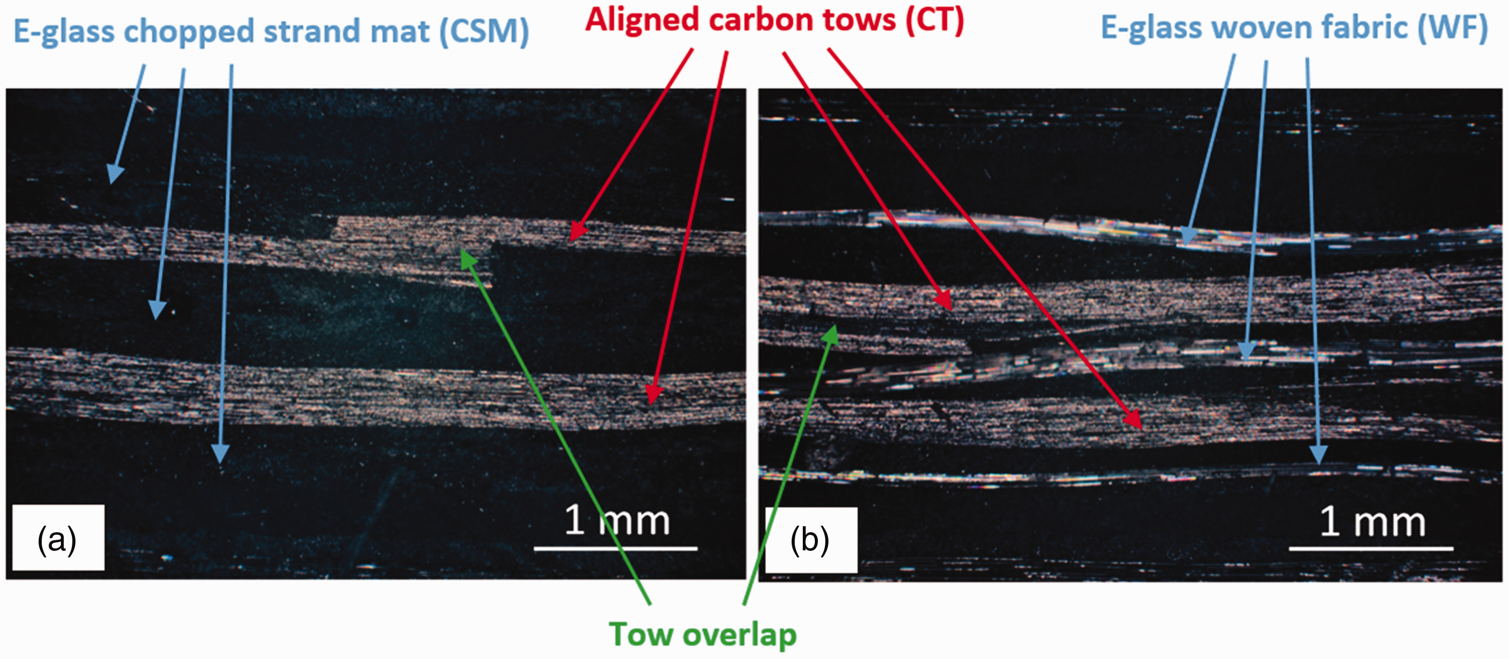
Considering the thickness difference among the hybrid laminates in Table 4, the discontinuous carbon tow layers in the aligned hybrid laminates are generally thinner than those in the non-aligned hybrid laminates. It implies that the fibre volume fraction of the aligned carbon tow layer is higher than that of the non-aligned one. Unfortunately, the accurate fibre volume fraction cannot be directly determined using the acid digestion approach or resin burn-off test as they are only applicable for single fibre composites. The fibre volume fractions of the aligned and non-aligned carbon tow layers were thus estimated based on the areal weight difference between the E-glass non-hybrid WF laminate and its two hybrid WF/CT laminates, assuming that the fibre volume fraction of the E-glass layers is constant. An area of about 350 mm2 was cut from each laminate and weighed after it was dried in an oven at 55℃ for 2 h using an analytical balance. Knowing the densities of their constituent materials (ρE-glass = 2.6 g/cm3, ρcarbon = 1.8 g/cm3 and ρepoxy = 1.1 g/cm3), the fibre volume fraction in the random and aligned carbon tow layers in the hybrid WF/CT laminates is estimated to be 42.8% and 46% respectively, neglecting void content.
Tensile testing
In a generic hybrid composite, two fibre types are brought together in a single composite. The two fibre types are typically referred to as low elongation (low failure strain) and high elongation (high failure strain) fibres.7,17–20 They, when used in appropriate proportions, can be utilised as a potential strategy for toughening or introducing pseudo-ductility in an otherwise brittle fibre-reinforced composite. In this work, the aligned discontinuous carbon fibre tow layers were hypothesised to act as the low elongation layers, while the E-glass CSMs or WFs as the high elongation layers. The tensile behaviour of the hybrid laminates was investigated to assess the influence of the aligned and non-aligned carbon fibre tows on their ductility, in comparison to the baseline non-hybrid laminates.
Test set-up
The tensile tests were performed on an Instron hydraulic testing machine at a crosshead displacement speed of 1 mm/min. The nominal stress was determined using the initial width and average thickness of the gauge section of each specimen, while the global strain (or apparent strain) was approximated using the crosshead displacement. This is a reasonable approximation provided that the stiffness of the test machine is much higher than that of the specimens and no specimen slippage occurs at the mechanical grips. It is sufficient in this study for comparing the macroscopic tensile behaviour of the hybrid and non-hybrid composites. Modulus was estimated from the slope of the apparent stress–strain curve within the strain interval of 0.05–0.25%. Strength data reported in this study refer to ultimate strength which corresponds to the peak load reached in the load–displacement curve, while strain to failure corresponds to the strain where the specimen loses its load-carrying capability (a sharp load drop).
Test results
The experimental results are summarised in Table 4 and all failed specimens are shown in Figure 10. Specimens that failed at the tabs as indicated in Figure 10 were discarded from the analysis. Figure 11 presents the apparent stress–strain curves for all the specimens without tab failure from each laminate.
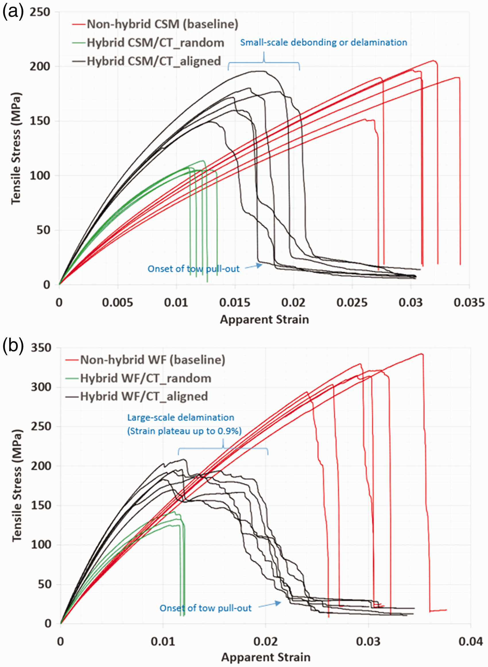
Failed specimens of (a) non-hybrid E-glass CSM, (b) non-hybrid E-glass WF, (c) hybrid E-glass CSM/CTrandom, (d) hybrid E-glass WF/CTrandom, (e) hybrid E-glass CSM/CTaligned and (f) hybrid WF/CTaligned laminates. Stress–strain curves of specimens of (a) non-hybrid E-glass CSM against hybrid E-glass CSM/CT laminates; (b) non-hybrid E-glass WF against hybrid E-glass WF/CT laminates.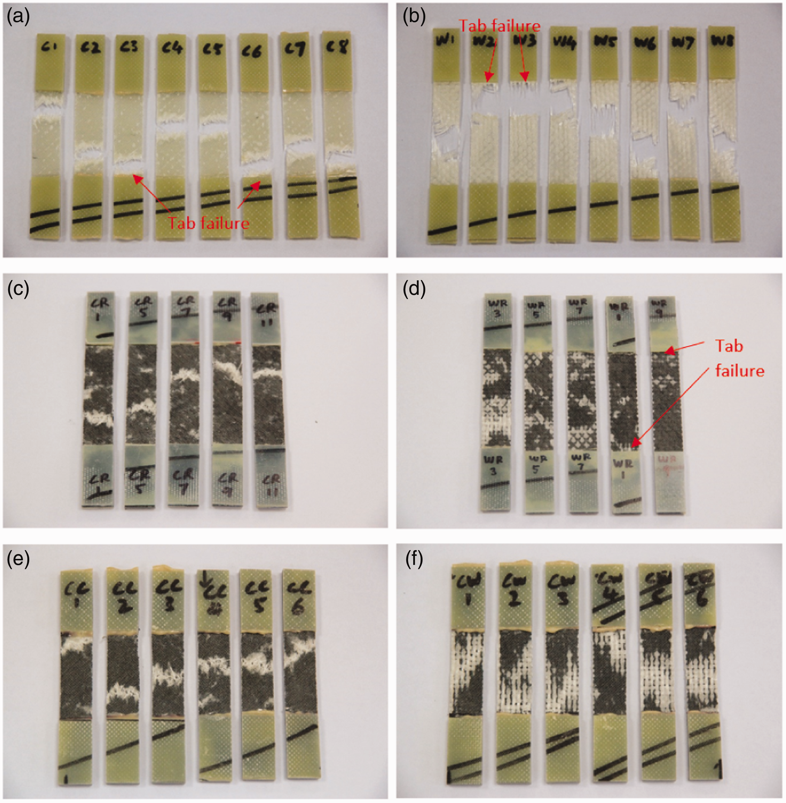
Aligned hybrid vs. non-hybrid composites
Comparison of the results between the aligned hybrid and the non-hybrid composites shows that the failure of the former is progressive compared to the catastrophic one of the latter. The brittle fracture of the non-hybrid E-glass CSM and WF laminates is evident in Figure 10(a) and (b), also indicated by the sudden stress drop in the stress–strain curves (Figure 11). On the contrary, the specimens of the hybrid E-glass CSM/CTaligned and WF/CTaligned display some degree of integrity even after the major load drop without breaking immediately into two halves (Figures 10(e) and (f)). For the hybrid laminates, failure mainly occurs in the form of debonding or delamination along the E-glass and aligned carbon tow interface as indicated by the whitened areas on the surface of the failed specimens. The scale of delamination/debonding damage in the hybrid E-glass CSM/CTaligned laminate is much smaller compared to the hybrid E-glass WF/CTaligned laminate.
The small difference in strength of the non-hybrid E-glass CSM (187 MPa) and the hybrid E-glass CSM/CTaligned laminates (172 MPa) suggests that both of them fail by a similar matrix-dominated failure mode. In the hybrid CSM/CTaligned laminate, multiple microcracks are initiated simultaneously at the tow ends or resin-rich areas over the laminate, which explains the non-linearity and the slight stress drop after the peak in the stress–strain curves (Figure 11(a)). Main failure then occurs at the critical cross-section of the laminate where there is accumulation of sufficient microcracks, which quickly propagate through the thickness in the form of stepwise strand/tow debonding and delamination between the randomly oriented E-glass strands and the aligned carbon tows following a path of least resistance, as shown in Figure 12(a). The stress–strain curves end with a shallow negative slope which indicates a tow pull-out stage. The strain at the onset of tow pull-out as indicated in Figure 11(a) is taken as the strain to failure for the hybrid E-glass CSM/CTaligned specimens. No fibre breakage is noticeable in the failed specimens.
Micrographs showing (a) matrix dominated failure in the hybrid CSM/CT laminate via transverse strand debonding, pull-out and inter-tow delamination at the carbon tow overlaps; (b) large-scale delamination failure in the hybrid WF/CT laminate.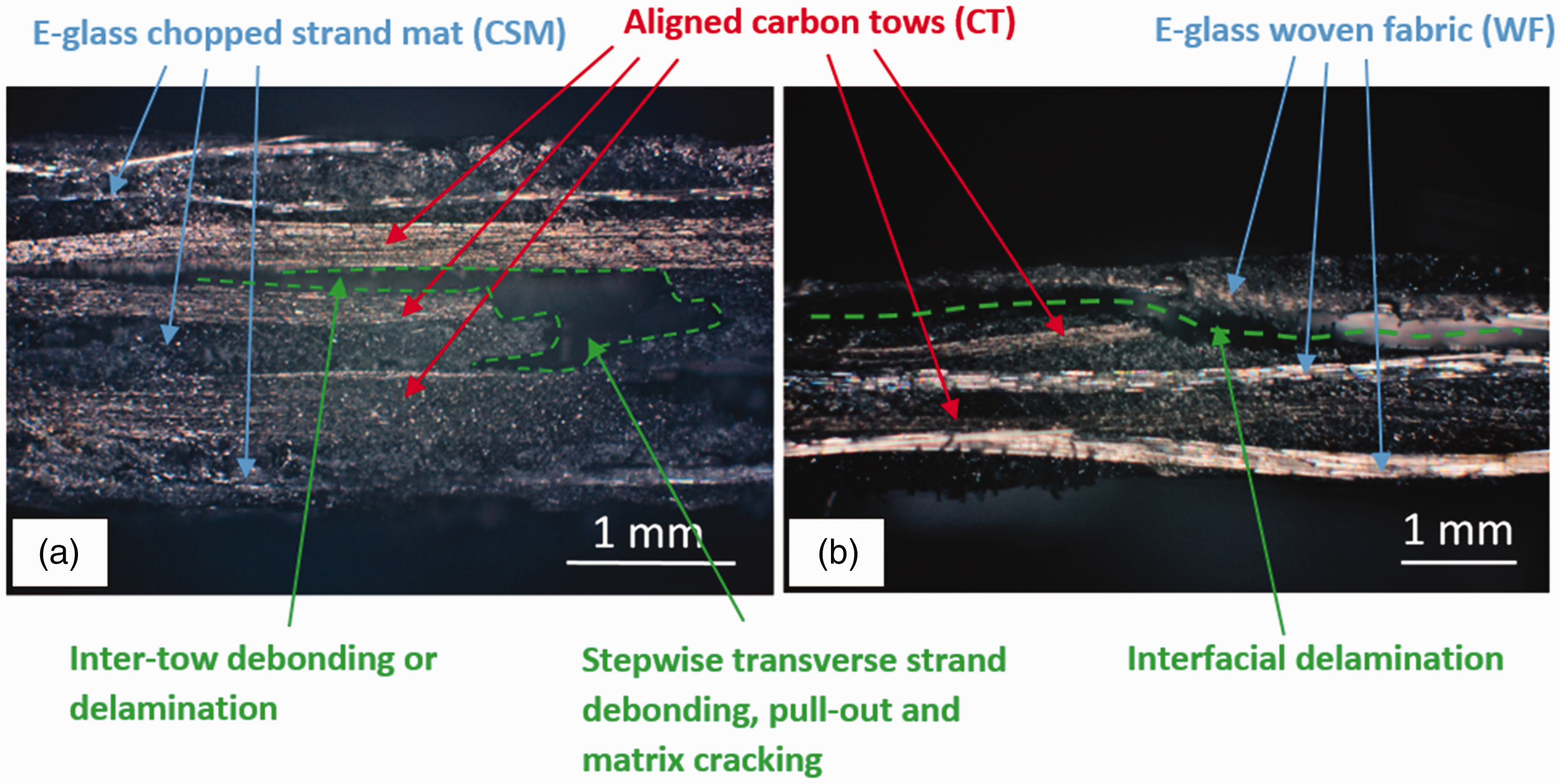
Stages of progressive failure are more pronounced in the hybrid E-glass WF/CTaligned laminate (Figure 11(b)). Similar to the hybrid E-glass CSM/CTaligned, multiple microcracks are initiated at the tow ends, resulting in a small stress drop from the peak stress. It then triggers large-scale delamination along the interfaces between the E-glass WF and the aligned carbon tow, as shown in Figure 12(b). The extensive delamination propagation is indicated by the stress plateau (extending as far as 0.9% strain) in the stress–strain curves (Figure 11(b)), before losing its load-carrying capability gradually. As can be clearly seen in Figure 10(f), full delamination over the whole gauge length is however arrested, possibly by the thickness variation in the aligned carbon tow layers. This is then followed by tow pull-out and straightening of the delaminated E-glass WFs in the final stage of the stress–strain curves. The strain at the onset of tow pull-out as indicated in Figure 11(b) is taken as the strain to failure for the hybrid E-glass WF/CTaligned specimens.
Owing to the aligned carbon tows, the apparent moduli of the hybrid E-glass CSM/CTaligned and WF/CTaligned laminates increase by 90.0% and 62.7%, respectively, compared to the baseline non-hybrid laminates. Their average ultimate load also increases by 35.6% and 33.5%. However, conversion of ultimate load into strength shows a strength knockdown of 7.9% and 40.3%, respectively, for the aligned hybrid laminates against the non-hybrid laminates. This will be discussed further in the next section.
Aligned vs. non-aligned hybrid composites
In Figure 11(a), the stress–strain curves of the hybrid CSM/CTrandom specimens show no sign of progressive failure where drastic load drop occurs instantaneously, as compared to the slight progressive failure displayed by the hybrid CSM/CTaligned specimens. It agrees with the smaller ‘whitened’ damaged area of the CSM/CTrandom specimens (Figure 10(c)) than that of the CSM/CTaligned specimens (Figure 10(e)). The failure mechanisms of the CSM/CTrandom and the CSM/CTaligned are similar, except that the cracks propagate much easier stepwise through the thickness in the CSM/CTrandom due to the shorter overlaps among the randomly oriented tows. There is no observable tow pull-out stage in the stress–strain curves of the hybrid CSM/CTrandom. Furthermore, the hybrid CSM/CTrandom shows unfavourably reduced apparent modulus (−19.3%) and ultimate strength (−37.5%) compared to the hybrid CSM/CTaligned.
Similarly, in Figure 11(b), the hybrid WF/CTrandom shows negligible progressive delamination compared to the hybrid WF/CTaligned. The contrast is apparent upon inspecting the extent of ‘whitened’ delamination damage on both specimens in Figure 10(d) and Figure (f). In the hybrid WF/CTrandom laminate, multiple microcracks are initiated simultaneously at the randomly oriented tow ends over the laminate, which leads to multiple localised delamination but they are difficult to propagate due to the random arrangement of the carbon fibre tows standing in their ways. The specimens then failed prematurely in a brittle manner at the critical cross-section where there is coalescence of microcracks. There is no observable tow pull-out stage in the stress–strain curves of the hybrid WF/CTrandom as well. The apparent modulus and ultimate strength of the hybrid WF/CTrandom laminate are reduced by 19.6% and 29.7%, respectively, compared to the hybrid WF/CTaligned laminate.
Discussion
The tensile test results demonstrate the importance of aligning the discontinuous carbon fibre tows for use in the hybrid composites. It offers significant improvement in stiffness, strength and ductility (i.e. progressive failure) over the non-aligned hybrid composites. The detrimental effects of embedding discontinuous carbon fibres directly within conventional E-glass fabrics/mats without the effort to align them are highlighted.
The results also show that the strength of the hybrid composites using discontinuous carbon fibres, aligned or non-aligned, is generally reduced compared to the baseline non-hybrid composites. This could be attributed to the heterogeneous fibre tow distribution, the presence of fibre ends and other characteristic defects typically associated with discontinuous fibre composites such as tow waviness and resin-rich areas1,21,22 generated by tow overlaps and gaps, as shown in Figure 8. These features act as stress concentrators, causing premature fibre/tow debonding from the matrix and delamination. SEM images of a polished cross-section of a failed hybrid CSM/CTaligned specimen in Figure 13 show evidence of carbon fibre/resin interfacial debonding (potentially leading to fibre pull-out) and a limited region where resin failed to impregnate a closely packed carbon fibre cluster which could also contribute to the reduced strength of the hybrid composites.
SEM images of a failed hybrid CSM/CTaligned specimen showing generally good resin impregnation within (a) the E-glass CSM layers and (b) the aligned carbon fibre layers, except in (c) limited regions where the carbon fibres are packed too closely together.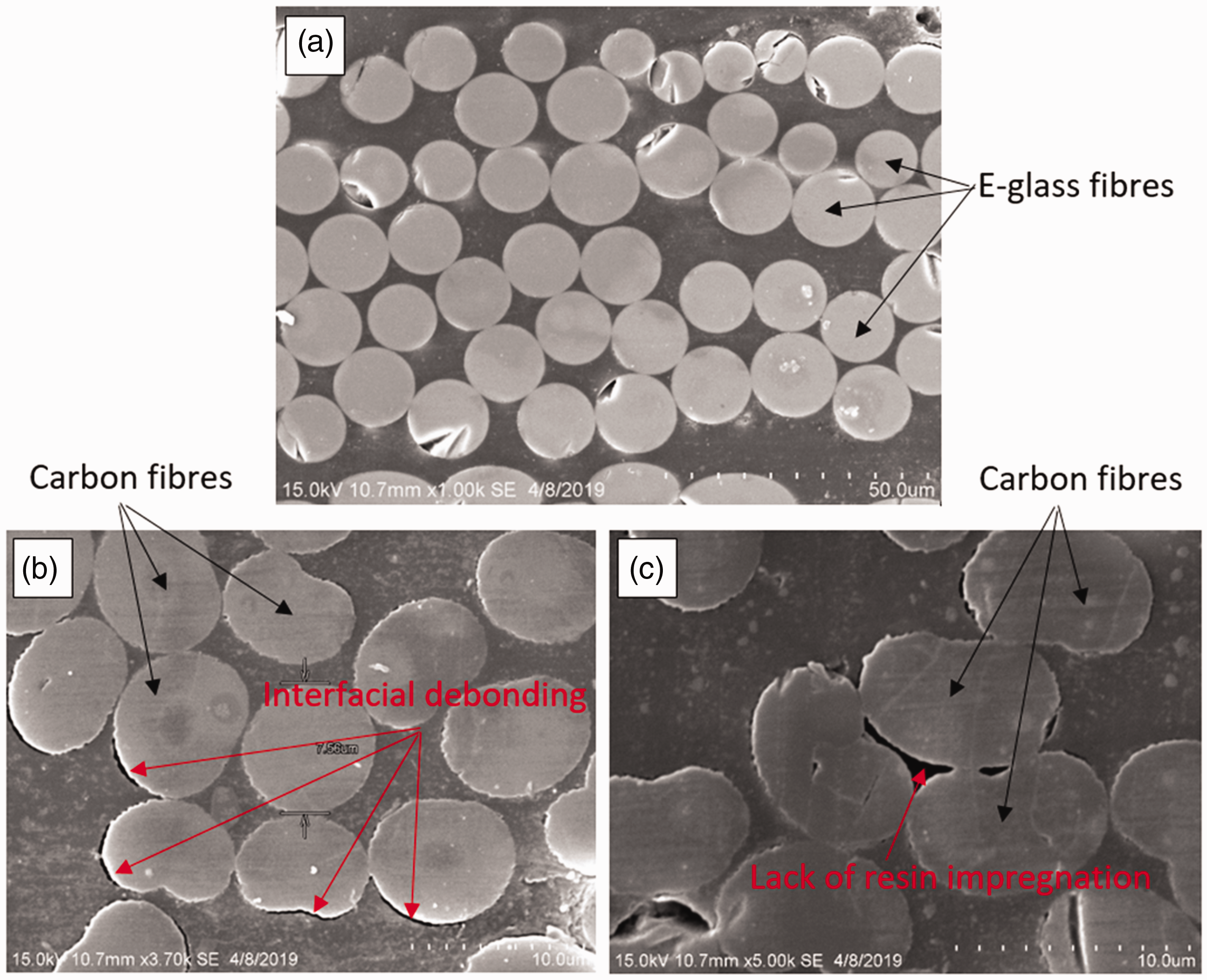
The pull-out failure mode shown in Figure 12 and the fibre/resin interfacial debonding shown in Figure 13(b) suggest that the effective tow length in the aligned hybrid composites is less than the critical tow length necessary to give fibre breakage for maximum utilisation of the fibre properties. Assuming that a fibre tow of width w and thickness t, which contains n single filaments of diameter φf, is analogous to a large single element with an elliptical cross-section, Harper et al.
23
proposed an analytical expression to predict the critical tow length, lc, as follows
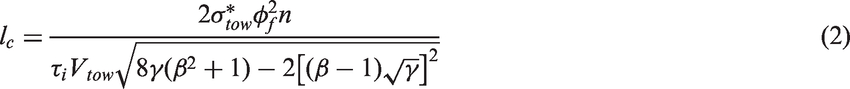
The test results demonstrate that a controlled subcritical damage or delamination event is essential to maintain the ductility of the hybrid composites after the damage onset. It could be maximised through multiple fragmentation or dispersed delamination, e.g. via interlaminating 30 µm thin carbon/epoxy plies between thicker glass/epoxy plies 18 or intermingling more than one discontinuous fibre types in the same layer. 7 Jalalvand et al. 19 introduced a damage mode map and showed that both the proportion and absolute thickness of the constituent layers have significant influences on the tensile response of hybrid composites. However, the smallest thickness achievable for the aligned carbon tow layer is bounded physically by the tow thickness itself. Note that utilising thinner tows also tend to disperse the resin-rich regions and therefore increase the homogeneity of the laminate for the same fibre volume fraction. While the tow thickness could be reduced via natural filamentisation or other mechanical means, a deposition thickness of a few tows is often necessary in order to obtain good areal coverage with minimal open pores. A detailed parametric study on the relative thickness of the constituent layers is needed to further understand their influences on pseudo-ductility.
The proposed dry alignment method provides a value-added manufacturing path for discontinuous fibre tows as a constituent material in cost-effective hybrid composites used for semi-structural applications. It can potentially be integrated in the existing composite moulding technologies. Although the hybrid composites do not outperform the baseline non-hybrid composites in terms of tensile strength, interlaminating aligned discontinuous fibre tows within the hybrid composites does offer an increase in tensile modulus and a tougher material response. This is of particular interest for automotive components which are typically driven by stiffness and damage tolerance rather than strength. The dry alignment method can be automated to tailor the thickness and orientation of the aligned fibres locally for functional efficiency. For instance, the discontinuous fibres can be aligned to carry off-axis loading, while the continuous ones are designed to take the principal stresses in a hybrid composite, or they can be deposited around sites with stress concentrations such as holes and notches as local reinforcement or toughening. The alignment method can also be easily scaled up for manufacturing large planar composite parts at a high production rate which is only limited by the size of the orientation unit.
Conclusions
A vibration-assisted dry alignment method has been presented for aligning discontinuous carbon fibre tows between conventional dry reinforcement mats or fabrics directly in a mould with the aim to fabricate cost-effective hybrid composites. The directionality of the tows is generated simply by having multiple discontinuous tows falling simultaneously through a vibrating orientation unit which consists of a series of narrow slits. Its feasibility is demonstrated by successful fabrication of two hybrid composite flat panels, in which two layers of aligned 12 mm long discontinuous carbon fibre tows were deposited between E-glass chopped strand mats or woven fabrics respectively, via an out-of-autoclave vacuum-assisted resin infusion process. In terms of alignment performance, 54% and 81% of the fibre tows were in the range of ±5° and ±10°, respectively. The tensile behaviour of the aligned hybrid composites was then compared against that of the non-hybrid composites and the hybrid composites with non-aligned carbon fibre tows. The test results clearly indicate the importance of having the discontinuous carbon tows highly aligned within the hybrid composites, showing increased stiffness (up to 24.4%) and strength (up to 59.9%) compared to the non-aligned hybrid composites. On the other hand, there is a strength knockdown (up to −40.3%) in the aligned hybrid composites when compared to the baseline non-hybrid composites, as the aligned carbon tows are shorter than the critical tow length therefore leading to premature tow pull-out. However, the aligned hybrid composites exhibit improved ductility, giving a non-linear pseudo-ductile response due to subcritical damage mechanisms such as inter-tow debonding and delamination, in contrast to the catastrophic brittle failure of the non-hybrid composites. The hybrid composites also generally display increased stiffness (up to 90%). Future works will focus on investigating the effect of aligned carbon tow length and layer thickness on the pseudo-ductility of hybrid composites.
Footnotes
Data Availability
The raw/processed data required to reproduce these findings are available upon request from the corresponding author (K.W.Gan@soton.ac.uk).
Declaration of Conflicting Interests
The author(s) declared no potential conflicts of interest with respect to the research, authorship, and/or publication of this article.
Funding
The author(s) disclosed receipt of the following financial support for the research, authorship, and/or publication of this article: This work was supported by the Fundamental Research Grant Scheme (FRGS/1/2015/TK09/USMC/03/1) of the Ministry of Higher Education of Malaysia.