Due to microscale fiber microbuckling, a fiber-reinforced soft composite demonstrates large macroscale bending deformation (e.g. 10% reversible macroscale compressive strain), which is larger than that of a convenient fiber-reinforced plastics (e.g. 1.5–2% elongation/compression at break). To investigate the deformation behavior, a normalized average energy density of a fiber-reinforced soft composite laminate was derived. By using a self-consistent approach according to the minimum energy principle, a series of analytical expressions were derived by a simplified theoretical method through solving simplified partial differential equations of average energy density. Furthermore, an improved numerical calculation method was developed using the full four terms of partial differential equations of average energy density by employing the results of simplified theoretical method as initial calculating values. The dimensionless results demonstrated that the trend correlated well between those two methods, and the improved numerical method obtained more accurate results than those of the simplified theoretical method. Analytical and numerical results in normalized expressions systematically descripted the bending large-deformation behavior including position of neutral surface and critical buckling, wavelength, amplitude, shearing strain, macroscale compressive/tensile strain, buckled fiber strain, and actuation moment. To design a fiber-reinforced soft composite for use in engineering, the simplified theoretical method is used to predict trend and obtain approximate results for preliminary design, and the improved numerical method is further used to check and obtain more accurate results on detailed design stage.
For conventional unidirectional fiber-reinforced plastics, failure modes under axial compression are generally shear failure, tensile failure, kink bands failure, or brittle fracture.1 Due to high stiffness of polymer matrix and low allowable deformation limit of fiber-buckling, it receives minimal attention on the generation and further evolution of non-destructive microbuckling for conventional fiber-reinforced plastics.2 On the other hand, investigation of local buckling phenomenon of soft materials or soft composite receives much more attention in recent years,3–6 which demonstrated multi-functional characteristics on the basis of special microscale buckling structures.7–9 The microbuckling of soft materials could be controlled by tuning various physical stimulus boundary conditions; in this manner, the mechanisms could be molded by mechanical instability methods.10 It shows several prospective engineering applications, such as reversibly sequestrated biomolecules and cells,11 microscale self-assemble 3D structures,12 and photonic structures in photovoltaics.13
The study in mechanical performances of a fiber-reinforced soft composite (FRSC) generally focuses on constitutive behavior of reinforcement phase and super-elastic matrix under finite strain condition and the microstructures.14 Homogenization theory can be used to analyze constitutive behavior of non-compressible, linear elastic soft matrix composites with periodic microstructures. The second-order homogenization theory has been employed to construct a constitutive relationship of a fiber-reinforced three-dimensional structure of flexible body. The Neo-Hookean model has been used to descript its extremely flexible matrix and fiber reinforcement; however, it was difficult to obtain microscopic local stress and strain.15,16 In addition, as the theoretical analysis method, the Bloch Wave theory has been used to solve the deformation and damage evolution problem for a laminated composite microstructure.17,18 In literature,19 three-dimensional problems of flexible bending state of fiber-reinforced flexible body has been solved by Bloch Wave theory method; hence, through the analysis of minimum element and 3D structure, 2D theoretical results (critical curvature, buckling wavelength, and amplitude) were obtained.20 According to the minimum energy principle, strain energy function with summation of different terms can be used to investigate deformation behavior.21–23 For a fiber-reinforced super elastic matrix composite with finite strain, average energy density function has been established to analyze the characteristics of microscopic bifurcation instability.24
As a typical smart FRSC, the shape memory polymer (SMP) and SMP composite (SMPC) exhibit high reversible strain at a temperature above the glass transition temperature (Tg) as well as high stiffness at below Tg.25–27 Due to fiber microbuckling, fiber-reinforced SMPC has demonstrated extremely high macroscale compressive strain.28,29 With those advantages, fiber-reinforced SMPC could be applied for deformable functional materials for space deployable structures,30 such as soft solar arrays and lens hood.
The study in the constitutive relationship of SMP has made progress;31,32 however, bending deformation and actuation regulation of SMPC have elicited minimal research attention. For deformation under pure bending of a SMPC, the cross section was divided into two regions, namely, the tension zone and the compression buckling zone, which were divided by the position of neutral plane.33 It assumed that all the compression regions are in the buckling state; hence, this theory is mainly suitable for SMPC at relatively large curvature. In addition, Jiménez and Pellegrino have systematically studied the tension, compression, and simple bending of fiber-reinforced flexible silicone resin.34,35 However, they still focused on full compression or tension but not multi-state characteristics of the bending cross section. Wang et al.36,37 have also developed the bending deformation model of a SMPC with considering the boundary effect. There is still a long way for SMPC to be applied in engineering, such as space deployable structures.38
The authors have already studied the bending deformation performance using a simplified theoretical method by solving simplified partial differential equations of total strain energy, which only contained two terms, and the basic analytical expressions in dimensional forms were discussed.39 However, there are two disadvantages in our previous study as follows: first, the comprehensive regulation and complete influencing variables of main resultant parameters have not been obtained. Second, the accuracy was low because the simplified system strain energy only contained two terms. Thus, in this study, the two according points were emphasized as follows. First, by solving the simplified two terms of the partial differential equations of normalized average energy density, the comprehensive regulation and complete influencing variables for the resultant parameters were completely given out in the dimensionless expressions, which could predict clear trend and obtain approximate values. Second, by employing the results of the aforementioned simplified theoretical method as the initial calculating values, an improved numerical method was developed by solving the full four terms of the partial differential equations of normalized average energy density. In this way, the more accurate results could be obtained; hence, this improved numerical method was proposed to be used to check and amend the results in detailed design stage for using a FRSC in engineering.
Macroscale bending large-deformation and microbuckling behavior
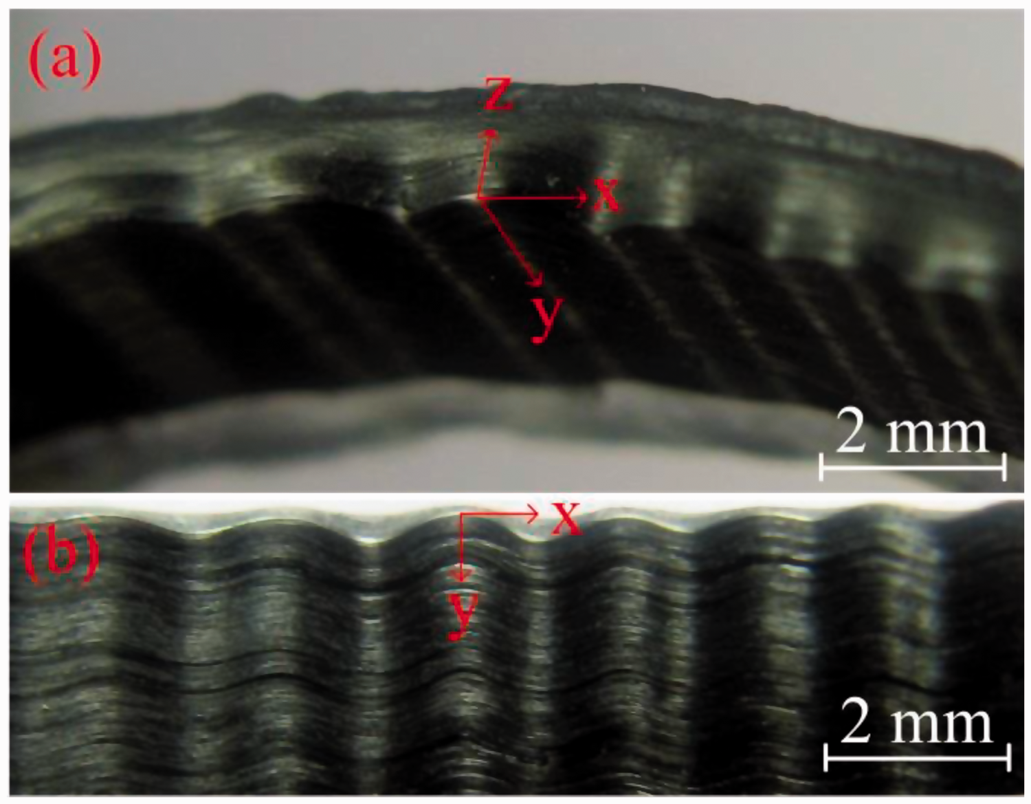
A FRSC is a stiffness fibers/soft-matrix composite; for example, the elastic modulus of fiber is 100 GPa, and the elastic modulus of soft polymer matrix is 10 MPa. Macroscale bending large-deformation of a FRSC can be realized and accurately designed because of associated formation of microscale fiber-buckling. Figure 1 shows macroscale bending large-deformation and sinusoidal microbuckling pattern of a unidirectional FRSC with fiber volume fraction of 20%. When z increased from zero along the thickness direction, the wavelengths of the buckled fibers were almost the same but, however, the amplitude decreased. On a fixed plane, the wavelengths as well as amplitudes were almost the same.
Macroscale bending large-deformation and sinusoidal microbuckling pattern of a unidirectional fiber-reinforced soft composite. (a) A macroscale bent FRSC with typical microbuckling configuration; and (b) a side view with regular sinusoidal microbuckling pattern.
When bending a FRSC laminate from plain state to curved configuration, the curvature, k, increases gradually, and the according characteristic is illustrated in Figure 2 and Table 1. Figure 2(a) to (c) show a typical procedure of macroscale deformation of a carbon fiber-reinforced FRSC. Figure 2(d) to (f) reveal evolutions of microscale morphology of a carbon fiber-embedded FRSC with extremely low volume fraction of fibers in the non-microbuckling zone, post-microbuckling zone, and post-microbuckling failure zone, respectively. For general bending deformation process for a FRSC, it is divided into three typical states (non-buckling, post-buckling, and failure states) by two critical curvatures (critical buckling and critical failure ). First, for a FRSC laminate, under an initial small bending deformation, the inner surface is in compressive stress state, and the outer surface is in tensile stress state. In this situation, neutral surface coincides with geometrical middle surface where stress and strain are exactly symmetrical; hence, the position of critical bending zcb = 0 and the position of neutral surface zns = t/2. Second, above a critical buckling curvature, , microbuckling occurs. In a further deformation process, amplitude of sinusoidal microbuckling on plane increases gradually (0 < zcb « zns < t). Third, above a critical failure curvature, , failure of a FRSC occurs (0 < zcb ≈ zns ≈ t), which contains fiber breaks, matrix failure, and delamination of fibers and matrix. The parameter characteristic during bending deformation from plain state to curved failure state is included and classified in Table 1.
A schematic illustration of the process of macroscale bending large-deformation and the associated evolution of the main parameters of a FRSC. (a) Macroscale bending small-deformation of a FRSC without fiber microbuckling (zcb ≈ 0 and zns ≈ t/2); (b) macroscale bending small-deformation of a FRSC with initial formation of fiber microbuckling (0 < zcb«zns < t); (c) macroscale bending large-deformation of a FRSC with typical fibers microbuckling (0«zcb ≈ zns ≈ t); (d) fibers without microscale microbuckling (k ≤ kcb); (e) microscale fiber microbuckling (kcb < k ≤ kcf); and (f) microscale fiber failure (k > kcf).
The parameters characteristic for a FRSC during the process of macroscale bending large-deformation.
State
Curvature k
and
Non-buckling state
k ≥ 0
= 0, = t/2
Critical buckling
0 < = k <
= 0, = t/2.
Post-buckling state
0 < < k <
0 < « < t
Critical failure
0 < < k =
0 < ≈ ≈ t
Failure state
< < k
0 < ≈ ≈ t
FRSC: fiber-reinforced soft composite.
The schematic illustration of its deformation model in Figure 2 describes general mechanism during the whole bending deformation procedure for a FRSC. In addition, two types of special conditions are able to describe deformation behavior and associated failure morphology for common fiber-reinforced composite with stiff matrix (e.g. elastic modulus of 1 ∼ 3 GPa) as follows. First, when ≈ ≈ 0, the critical microbuckling and critical failure occur almost at the same time. In this situation, kink bands failure, obscure microbuckling half-wavelength, or malposed patterns occurs; hence, transition mode with obvious and regular sinusoidal waves of fiber microbuckling could not be found. Second, when > ≈ 0, critical failure occurs before critical microbuckling. In this situation, brittle breaks of fibers and matrix appear; hence, microbuckling pattern cannot be found. This situation correlates with compression failure mode for most conventional fiber-reinforced plastics.
The minimal energy principle was used to derive the expression of key parameters, including position of neutral surface , position of critical buckling , half-wavelength λ, and magnitude A of the sinusoidal post-microbuckling wave. The total strain energy for a FRSC laminate needed to be obtained, and then solution method of partial differential equations was discussed. To describe the total strain energy U for a FRSC laminate, the cross section was divided into two types of areas: buckling area () and non-buckling area (). The terms of buckling area contain energy sub-terms: fiber-buckling deformation energy , matrix shearing deformation energy on plane, and matrix shearing deformation energy on plane. In non-buckling area, the energy terms include sub-terms in compressive and tensile states, namely fiber tensile deformation energy , tensile deformation energy , fiber compression deformation energy , and compression deformation energy . All these four sub-terms can be included in an expression integrating from to t along thickness direction of a FRSC laminate.
The normalized expression of each parameter was defined as , , , , , , , , . The normalized curvature considers the thickness affection when bending FRSC laminate specimen at a curvature radius r (). The maximum strain is located on the inner side, which is between (assuming the neutral surface is located at the outer surface) and (assuming the neutral surface is located at the geometrically middle surface). In this way, this normalized curvature not only directly reflects the evolution process of bending deformation of a FRSC with a special thickness, but also indicates the maximum compression strain level (). The normalized position of neutral surface () reflects the relative position of neutral surface compared with the thickness t(). In a similar manner, the critical position of microbuckling () reveals the relative position of critical buckling of a FRSC laminate with thickness, t. The normalized half-wavelength () indicates the ratio of half-wavelength to radius of a microbuckling fiber. The normalized amplitude () determines the ratio of amplitude to radius of a microbuckling fiber. The normalized position () denotes relative position along thickness direction, and the normalized diameter () indicates the ratio of fiber radius to FRSC laminate thickness.
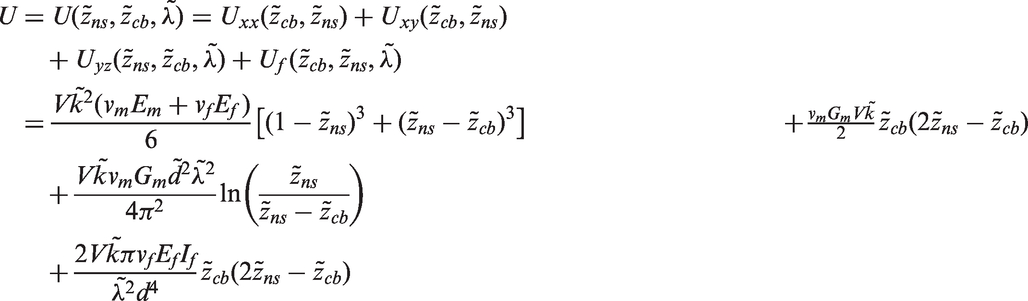
The expression of total strain energy was obtained with the aforementioned normalized parameters, which was in a similar manner as those in our previous study39:
describes tensile strain energy () and compressive strain energy () in non-buckling area (), including energy of matrix and fibers. In a low stretching or compression strain state (), local strain is homogenous for fibers and soft matrix nearby; hence, fibers and soft matrix are assumed to perform equal strain in accord with common fiber-reinforced composite. can be expressed as . In this non-buckling area, the normalized half-wavelength is excluded in .
reveals shear energy of soft matrix in buckling area on plane in the fiber-buckling area (). According to the deformation procedure, the soft composite was tightly bent around a cylinder hub without deformation in the z direction. When considering shearing deformation, shearing strain on plane is ignored, and the normalized half-wavelength is excluded in . On a special plane, both wavelength and amplitude keep uniform. The can be expressed as .
denotes shear energy of soft matrix on buckling area plane in the fiber-buckling area (). The amplitude varies along the thickness in z direction, and shearing strain exits. can be expressed as , where the normalized half-wavelength is included.
is energy of buckled fibers in the fiber-buckling area (). Considering the low strain and the large geometrically deformation, can be expressed as . Note that, in a simplified expression, is only written with unknown variables, , , and , but exclude the known materials or geometrical variables such as M, , or .
In a derivation process similar to our precious study,39 the new expression of total strain energy can be obtained.
where is volume of a FRSC laminate.
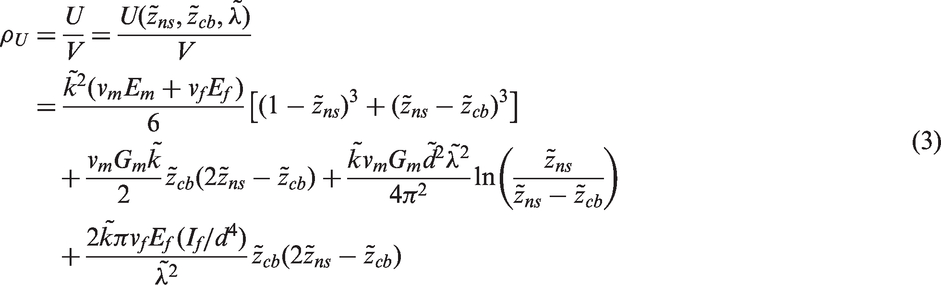
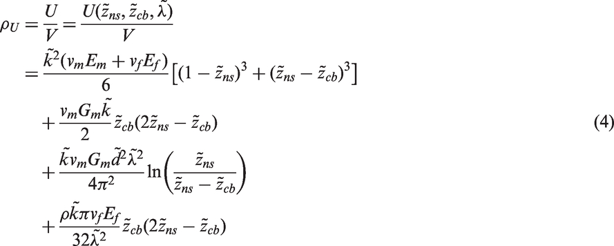
The average energy density in normalized expression was obtained:
Note that, is a dimensionless parameter. Specially, when considering a circular cross section , the average energy density in a normalized manner can be simplified as:
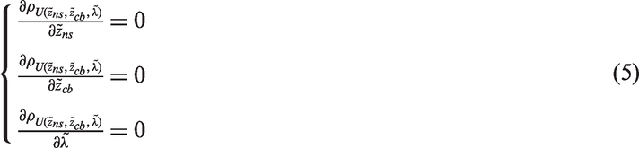
A standard method was used to solve the equation (3) to obtain key parameters. According to the minimal energy principle, partial differential equations were obtained in terms of three variables, namely normalized position of neutral surface , normalized position of critical buckling , and normalized half-wavelength .
However, it cannot obtain analytical results directly. Furthermore, without the relatively accurate initial values of the , , and , those partial differential equations cannot even be solved by numerical solution methods. Thus, two methods were considered to solve this problem. First, through a self-consistent approach, analytical results were obtained by solving simplified equations developed from equation (5); hence, a full set of system architecture was achieved to descript the trend of bending large-deformation and microbuckling behavior. Second, employing those simplified analytical solutions as initial values, accurate numerical solutions of equation (5) were obtained. Moreover, the actuation moment was first obtained, which is essential performance for shape memory FRSC using in space deployable structures.
The simplified theoretical method
A simplified expression is obtained only considering the first two terms, and , and neglecting the latter two terms, and .
Employing self-consistent approach as that in our previous study,39 it is supposed that
According to the principle of minimum energy and using variation method, the equation (7) with two variables, and , is solved by establishing the following partial differential equations:
When solving equation (8) with the variables and , analytical solutions are obtained. The normalized position of neutral surface can be expressed as:
where
The normalized critical buckling curvature is
The normalized critical failure curvature is influenced by strength limit of fibers, matrix, and cohesion between fibers and matrix. When is smaller than , neutral surface is located at geometrically middle surface ( = 1/2); hence, distribution of stress and strain follows the classic mechanics of materials. When , microbuckling occurs and neutral surface moves from geometrically middle surface toward outer surface gradually (). is only decided by the composite material properties, () and . Considering bending behavior of a FRSC, the separated parameter is determined by (); hence, different FRSC laminates may behave with the same bending performance, such as laminate I (thickness 1 mm and bending curvature k = 100 m–1) and laminate II (thickness 2 mm and bending curvature k = 50 m–1).
The normalized position of critical buckling is solved from the partial differential equations (equation (8)).
Similar to , where is smaller than , the neutral surface is located at the middle surface ( = 1/2), and there is no microbuckling (). When , the microbuckling occurs (), and the position of critical buckling moves from inner compressive surface toward outer surface gradually. The normalized position of critical buckling is also decided by () and .
The normalized half-wavelength can be solved from the partial differential equation:
The analytical expressions of and can be inverted into the equation (13), and is obtained:
For a typical FRSC, Em is much lower than Ef, but vm and vf are comparable; hence, can be neglected in this expression . M is employed in this expression:
When considering the carbon fiber with circular cross section, . Then the equation (14) can be simplified as:
When < , there is no buckling, and is positive infinite. When ≥ , the decreases gradually with increasing .
Other key analytical expressions are given and explained in the following. The fiber’s microbuckling normalized amplitude :
where . When considering the carbon fiber with circular cross section, , and equation (17) is simplified as:
When < , there is no buckling, and the normalized amplitude is zero. When ≥ , the normalized amplitude of microbuckling increases gradually with the increase in bending curvature .
When considering equation (9), the macroscale strain of a FRSC laminate along x axis is
where
The shearing strain of matrix in microbuckling area on plane is
The shearing strain of the matrix in microbuckling area on plane is
The axial strain of the buckled fiber reinforcement is
The actuation moment can be derived from system total strain energy.
where θ is deformation angle of a FRSC during bending process at a certain curvature k.
Finally, from the point of view of force equilibrium on cross section, the equilibrium equation between tensile area and macroscale compressive (microbuckling) area can be expressed as follows:
Elastic modulus of the tensile area is several orders higher than that of macroscale compressive (microbuckling) area at a soft state; hence, the former’s overall area is much smaller than that of the latter.
The improved numerical calculation method
The analytical results are unable to be obtained when trying to solve the partial differential equations of total strain energy (equation (5)). Furthermore, without the relatively accurate initial values of the , , and , this partial differential equations cannot even be solved by numerical solution method. Alternatively, a numerical calculation method was employed to numerically solve the partial differential equations (equation (5)), by using (equation (9)), (equation (12)), and (equation (14)) as initial calculating values on the basis of the simplified theoretical method. The commercial software Mathematica was used to calculate the numerical results. The “FindRoot” function was mainly used in the program of numerical calculation. Results are compared between the simplified theoretical method and the improved numerical calculation method with various values of composite coefficient M, where
By Mathematica software, through the improved numerical calculation method, the following key parameters were calculated: normalized position of neutral surface , position of critical buckling , half-wavelength , normalized amplitude , shearing strain , shearing strain , macroscale compressive strain , macro tensile strain , strain of fibers , total energy U, and the actuation moment T. The evolution regulation is discussed and compared in the next section. Note that, as a typical variable stiffness polymer material at different temperatures, a SMP is the soft matrix of a FRSC by default in calculation and comparison in the following sections.
Typical behavior of macroscale bending large-deformation and microbuckling
Figure 2 and Table 1 indicate general deformation process of a FRSC from plain state without buckling to post-microbuckling, and finally to material failure. To study qualitative and quantitative feature of key parameters during bending deformation, the comparison between simplified theoretical method and improved numerical calculation method are discussed. Three typical values of composite coefficient M (Em = 15, 100, and 1000 MPa, Gm = Em/3, Ef = 210 GPa, and vf = 20%) were calculated. When Em = 15 MPa, it is the elastic modulus at a temperature around Tg for a SMP and is able to perform high reversible strain (e.g. 100%). When Em = 1000 MPa, the SMP is at a stiff state at room temperature; moreover, for a convenient fiber-reinforced plastics, the elastic modulus of polymer matrix is at this order of magnitude. When Em = 100 MPa, the associated deformation behavior performs between those of Em = 15 MPa and Em = 1000 MPa. The normalized curvature of critical bending () are 0.000348 (Em = 15 MPa), 0.002315 (Em = 100 MPa), and 0.044818 (Em = 1000 MPa), respectively. Accordingly, at the critical buckling state, the maximum compressive strain on inner surface () are 0.0174% (Em = 15 MPa), 0.116% (Em = 100 MPa), and 2.241% (Em = 1000 MPa). Geometrical dimensions are length l = 30 mm, width w = 5 mm, and thickness t = 1 mm.
The normalized position of neutral surface
Considering the normalized position of neutral surface () with various values of composite coefficient M, the value of maintains at 1/2 before microbuckling occurs, as shown in Figure 3. When beyond the critical bending curvature, the microbuckling occurs and gradually moves toward the outer surface. For a FRSC with a soft matrix, can easily approach the area around outer surface, such as the zone . In contrast, for a composite with a stiff polymer matrix, can only move a bit away from the geometrical middle surface, such as the zone . When comparing calculated by the simplified theoretical method and improved numerical calculation method, they show the same trend. However, the latter one is smaller than the former one, and the difference becomes smaller as M increases. For a soft SMP matrix (e.g. Em = 15 MPa), the SMPC is able to undergo numerous deformation cycles with macroscale bending large-deformation (e.g. , namely k = 100 m–1, and t = 1 mm), and the associated maximum compression strain is extremely high (e.g. = 9–10%). However, for a stiff polymer matrix composite, just like a convenient fiber-reinforced plastics, the failure occurs before the formation of fiber microbuckling. Thus, the microbuckling of fibers cannot be observed for convenient fiber-reinforced plastics. Finally, for a soft matrix, from the point of view of force equilibrium of the cross section (equation (24)), the area ratio of macroscale compression at the cross section has to be high due to its low macroscale compression modulus.
The normalized position of neutral surface .
The normalized position of critical buckling
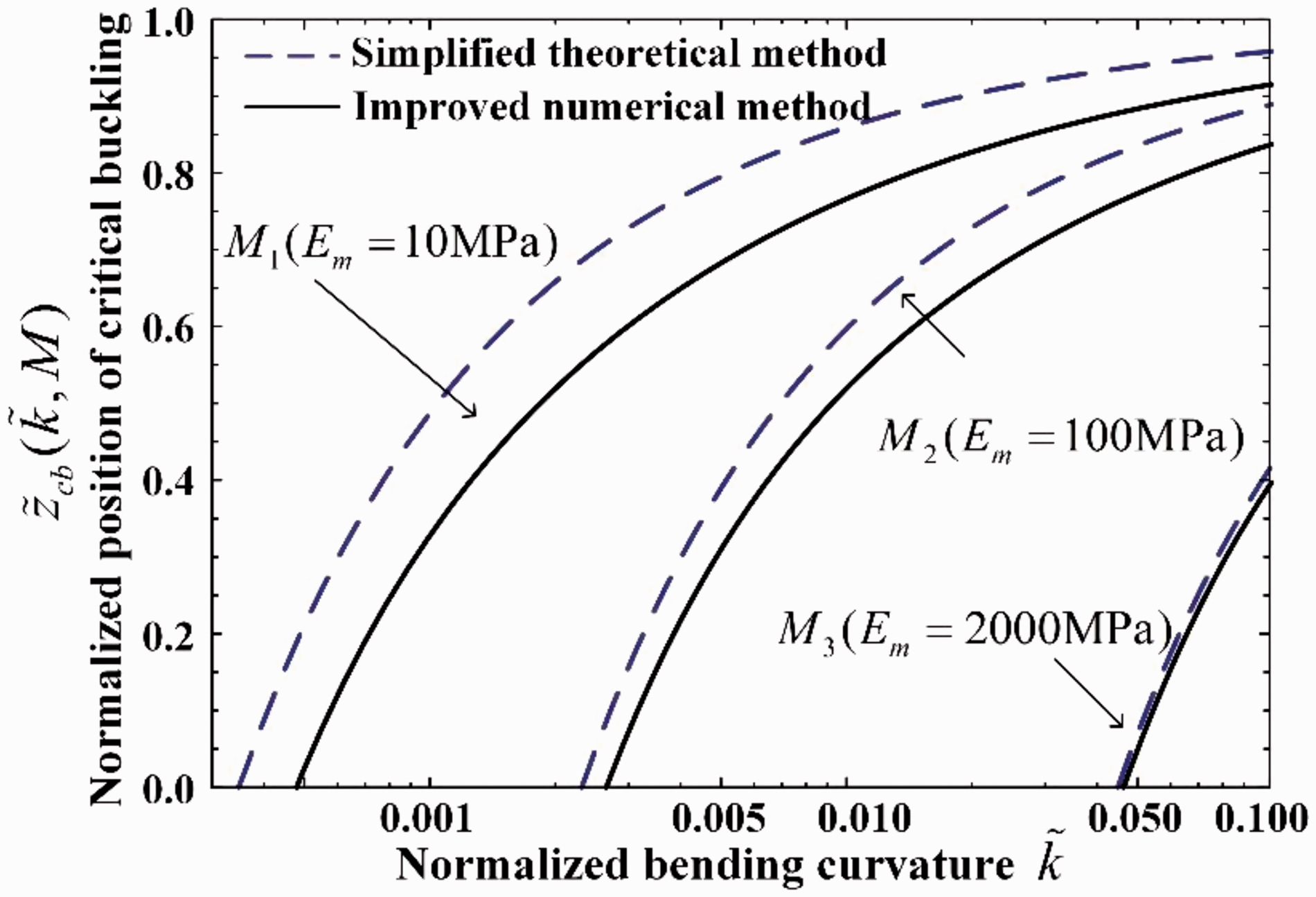
When discussing the normalized position of critical buckling () with various composite coefficient, M, it keeps at zero till the microbuckling occurs, and then it gradually moves toward the outer surface in tensile state. As shown in Figure 4, quickly shifts toward the area of outer surface. For a stiff polymer matrix composite, the movement range of is limited within the zone . The is always lower than . The improved numerical calculation results are lower than the simplified theoretical method results, and the difference will be narrower when M increases. When considering the actual deformation and material failure for a FRSC, can approach the outer surface and suffer from numerous cycles with large-deformation. However, for a convenient hard polymer matrix composite, failure appears but microbuckling does not occur.
The normalized position of critical buckling .
The normalized half-wavelength
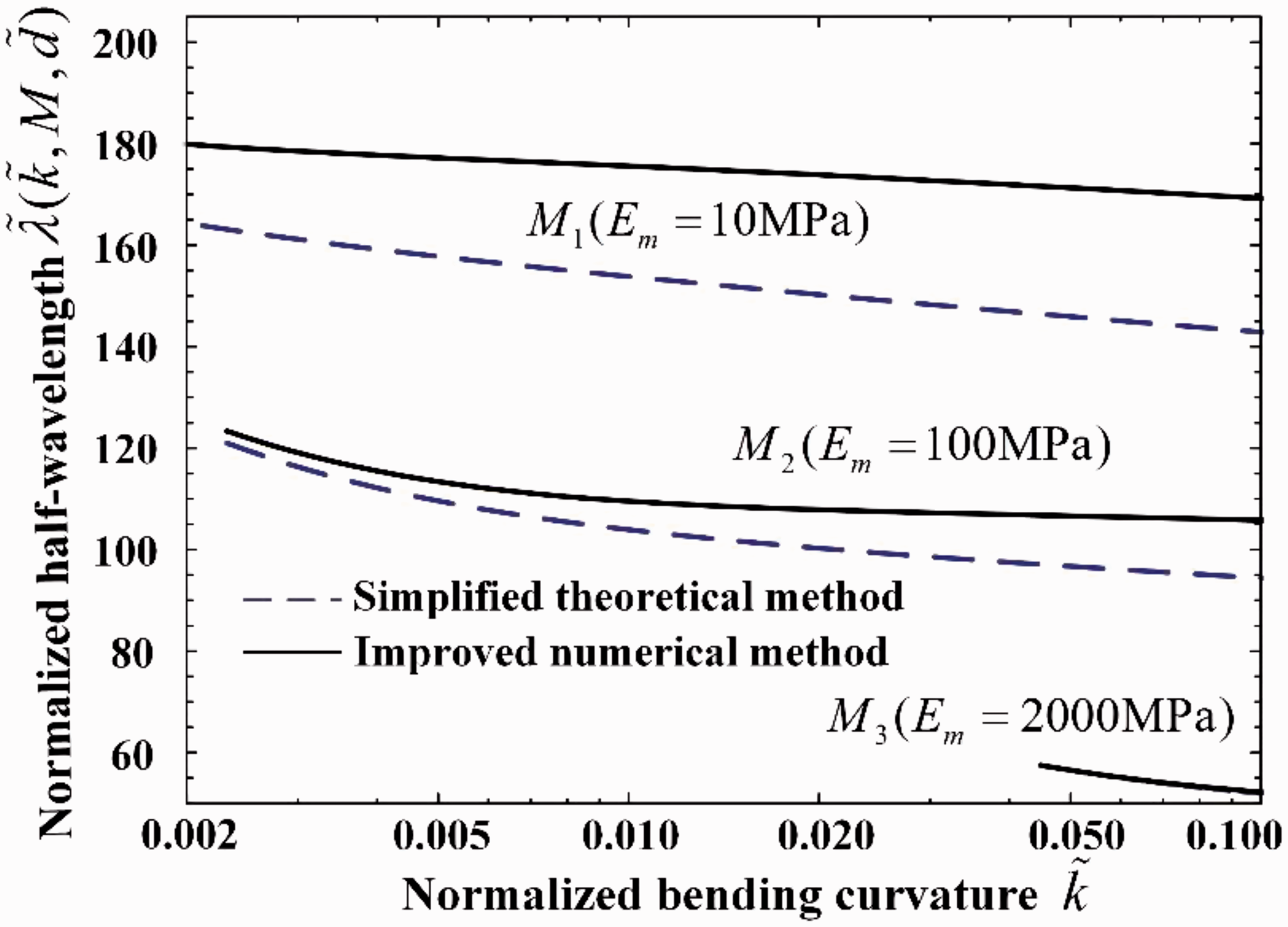
The normalized half-wavelength () reveals the ratio of half-wavelength to diameter of a microbuckling fiber. The half-wavelength decreased slowly with gradually increasing the bending curvature, which can be explained as that the buckled fibers bundles with short wavelength will store a high density of strain energy at a small bending radius. The half-wavelength is the same along the thickness direction z as shown in Figure 5. When increasing M, decreases apparently, which also implies that formation and followed change of fiber post-microbuckling is more difficult within a stiff polymer matrix. At this typical soft state (Em = 15 MPa) of a FRSC under a typical bending deformation from a plain state to a normalized curvature , calculated by the simplified theoretical method drops from about 195 to 140. calculated by the improved numerical calculation method drops from about 200 to 170. When M increases, the difference of calculated from these two methods becomes narrow. For a carbon-fiber-reinforced SMPC with a soft polymer matrix (Em = 15 MPa), the half-wavelength is normally 1.2 mm (170 × 7 µm and carbon fiber diameter d = 7 µm) –1.4 mm (200 × 7 µm), where its length is 170–200 times longer than carbon-fiber.
The normalized half-wavelength .
The normalized amplitude
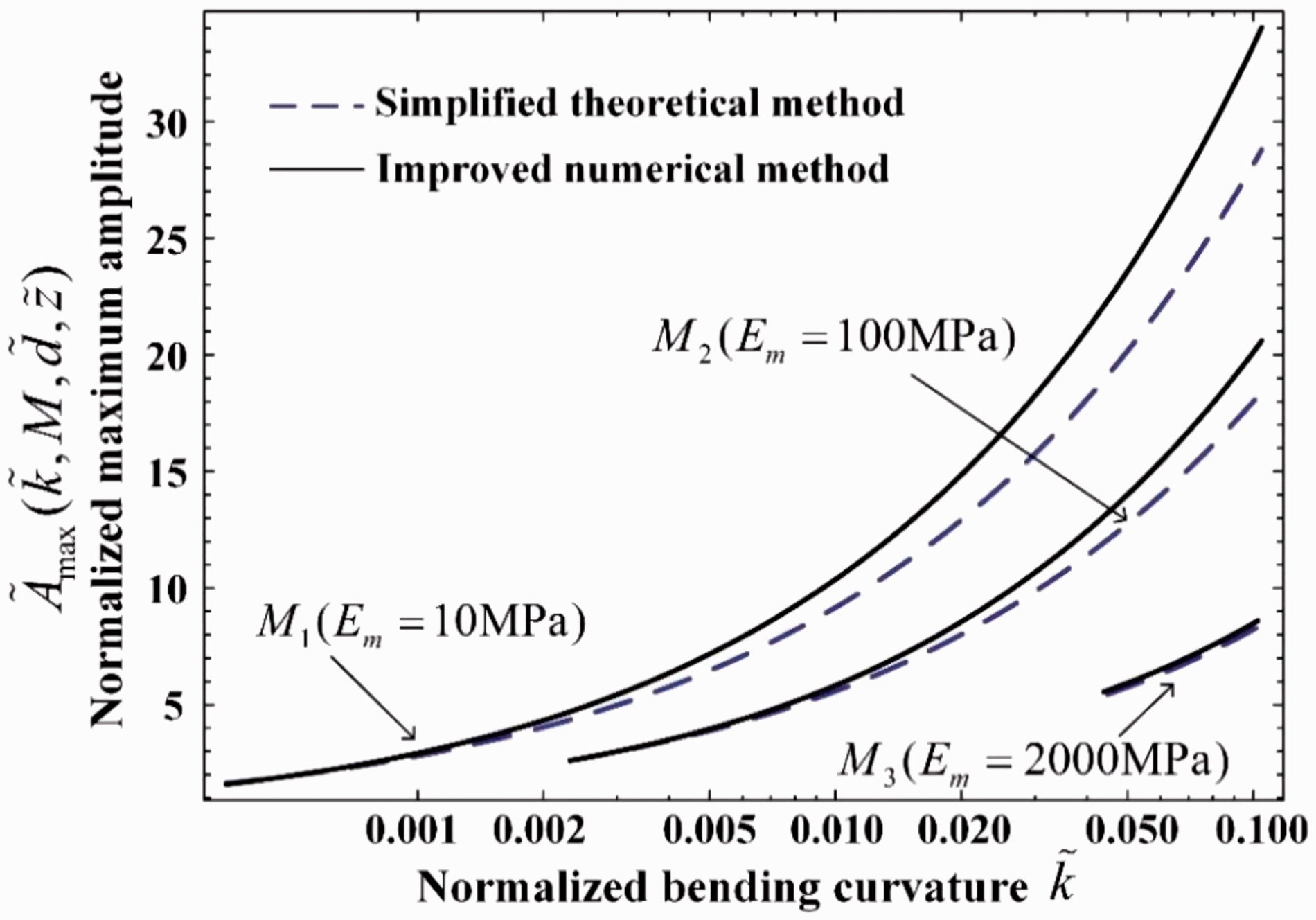
The normalized amplitude () indicates the ratio of the amplitude to the diameter of a microbuckling fiber. Along the thickness direction z as shown in Figure 6, increases from zero at the position of critical buckling to a maximum value at the position of inner surface. Different with the evolution of , naturally increases with increasing bending curvature, which causes large macroscale strain for a soft composite. For instance, the macroscale reversible strain is about 9∼10% for a FRSC (Em = 15 MPa) due to the microbuckling with a fiber-buckling amplitude much larger than the diameter of fiber. This macroscale compression strain is much higher than the fiber elongation limit at break.
The normalized maximum amplitude .
The shearing strain
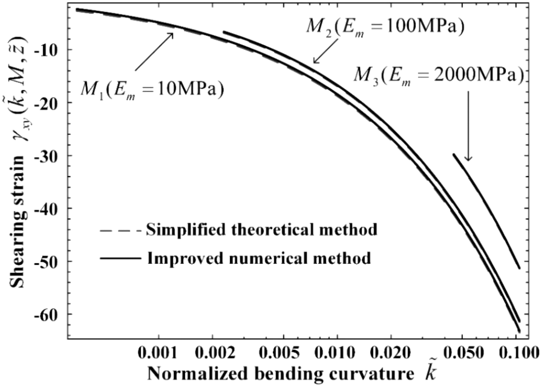
According to the deformation operations, the soft composite specimen was tightly bent around a cylinder hub without deformation in the z direction. In the plane, an array of in-plane microbuckling of fiber bundles form, and the in-plane shearing strain is uniformly distributed at a certain z position. In other words, the wavelength and amplitude are uniform on a plane. Furthermore, the shearing modulus of reinforced fibers is much higher than that of soft polymer matrix. If the equal stress assumption is employed, the shearing strain of reinforced fibers would be much lower than that of soft polymer matrix. In this way, the shearing deformation of reinforced fibers can be neglected, and . The only exists at z direction in range from inner compressive surface to critical buckling position . From Figure 7, the maximum shearing strain at inner surface increases quickly with increasing bending curvature, which approaches approximate 50–60% with . The results from the simplified theoretical method and improved numerical calculation method correlate well with each other. The shearing deformation is parallel mode. For the composite coefficient M (Em = 2000 MPa), the theoretical value of shearing deformation is above 50%. However, the actual shearing deformation is much lower than 50%; hence, the shearing deformation of soft polymer matrix and the corresponding microbuckling do not appear actually.
Maximum shearing strain on the inner surface ().
The shearing strain
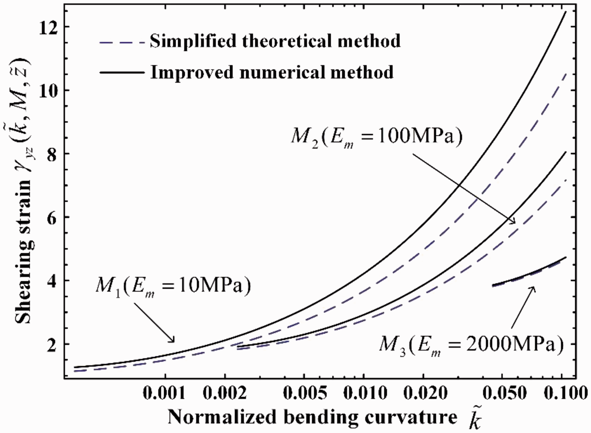
Deformation on plane is the shearing mode. Due to different microbuckling amplitudes between two closed layers in z direction, shearing deformation form in this area. On plane, half-wavelength and amplitude of fibers gradually changed along z direction and . The exists in range from inner compressive surface to critical buckling position . Similar to , as shown in Figure 8, the maximum shearing strain is on inner surface, and it slowly approaches approximate 8–12% with for a soft polymer matrix. The result by improved numerical calculation method is higher than that by simplified theoretical method. Compared with (the maximum value 50∼60%), the (the maximum value 8∼12%) is lower, which implies that shearing deformation on plane is main deformation mode in buckling area.
Maximum shearing strain on the inner surface ().
The macroscale compressive strain
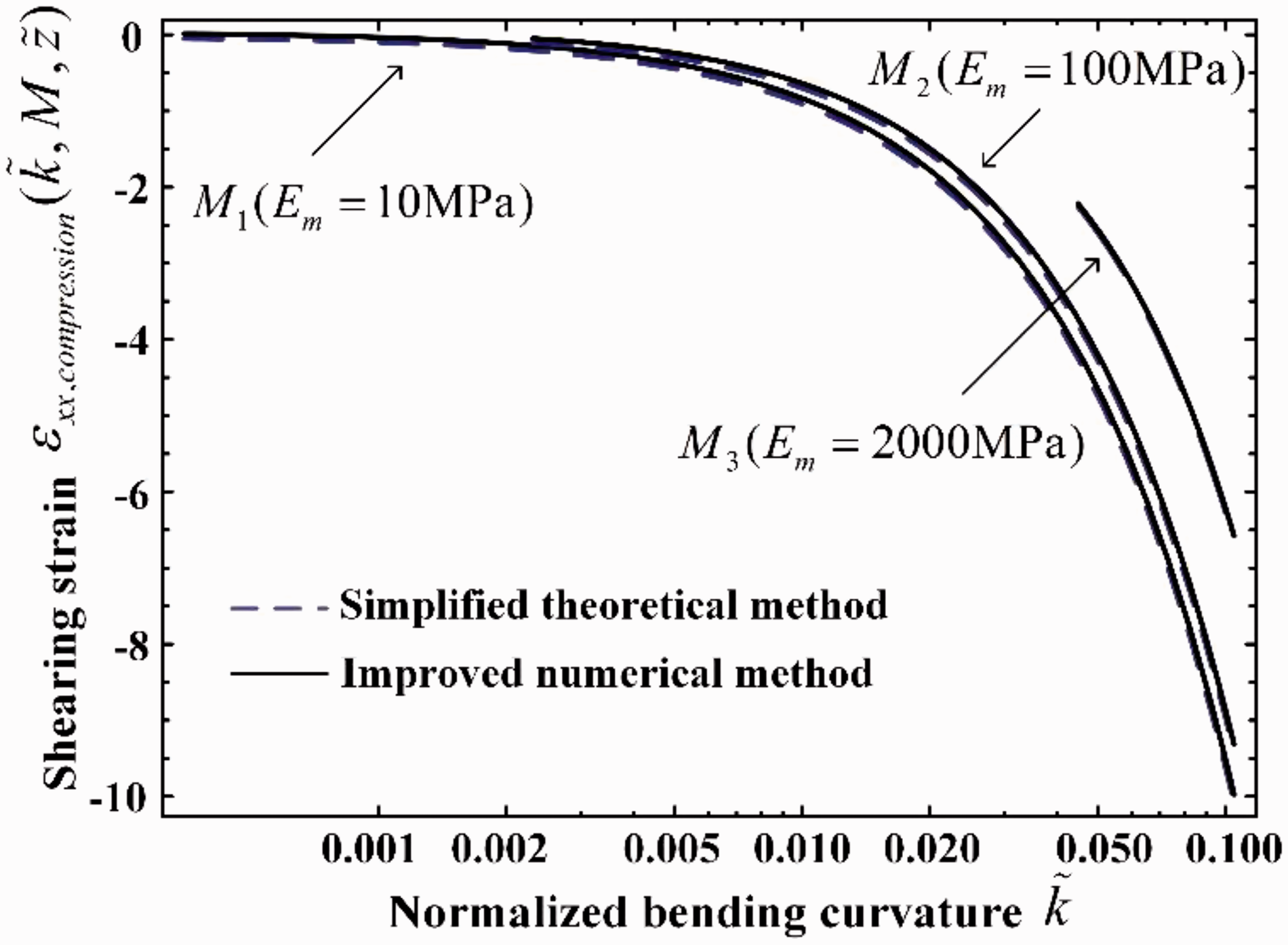
Compared with convenient fiber-reinforced plastics, the large macroscale compressive strain is the most important performance due to the mechanism of fiber microscale buckling. In thickness z direction, macroscale compressive strain increases from zero at position of neutral surface () to the maximum value on inner surface (). On inner surface, as shown in Figure 9, the macroscale strain approaches approximate 9–10% when the normalized bending curvature gradually approaches 0.1 (a typical value: thickness 1 mm, and bending curvature 100 m–1, namely bending radius 10 mm). On the other hand, for convenient fiber-reinforced plastics, ordinary compressive strain limit is approximate 1.5–2%. Beyond the deformation limit, failure will affirmatively occur. Thus, this microbuckling deformation mode distributes a prospective picture to obtain an extremely large-deformation for composite consist of stiff fibers and soft polymer matrix. Especially, for a SMPC, it can obtain large material compressive strain and large geometrical structural deformation above Tg. A SMPC can also exhibit the same magnitude of elastic modulus (i.e. 10 GPa or 100 GPa) as well as structural stiffness just like the convenient fiber-reinforced plastics. With those above advantages, this soft and smart SMPC is prospectively developed for application in the deployable structures in space.
The maximum macroscale compressive strain .
The macro tensile strain
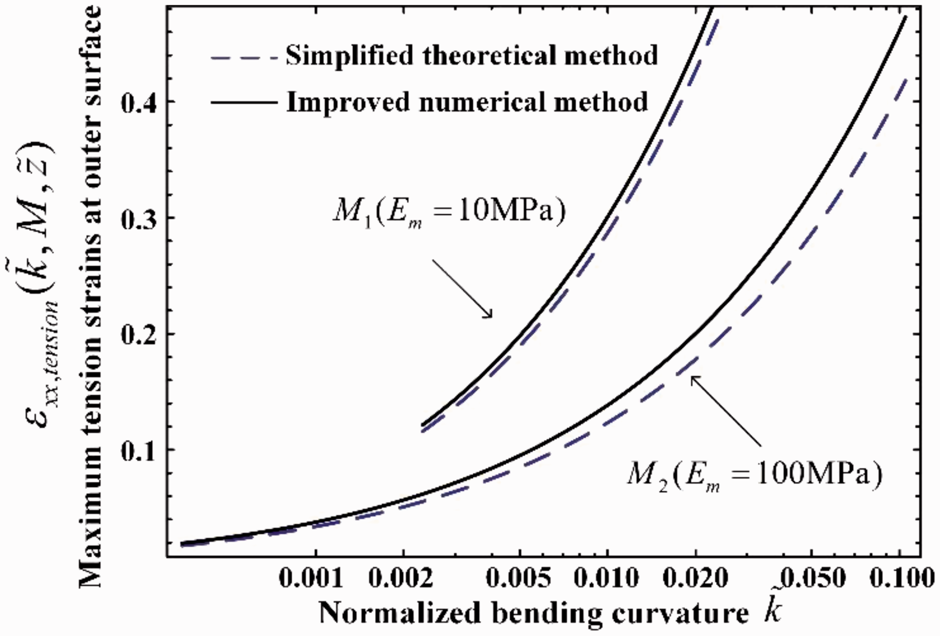
Macroscale tensile strain is comparable with that of convenient fiber-reinforced plastics. For reinforced fibers and polymer matrix, equal strain assumption is employed in tensile strain area (). From the point of view of force equilibrium of the cross section (equation (23)), the area ratio of tensile strain is extremely low due to its high tensile modulus that is enough to maintain force equilibrium on plane. As revealed in Figure 10, maximum tensile strain on outer surface () rises slowly with increasing bending curvature, and it is approximately 0.4–0.5%, which is much lower than macroscale compressive strain (9–10%) and shearing (50–60%).
The maximum tensile strain at the outer surface .
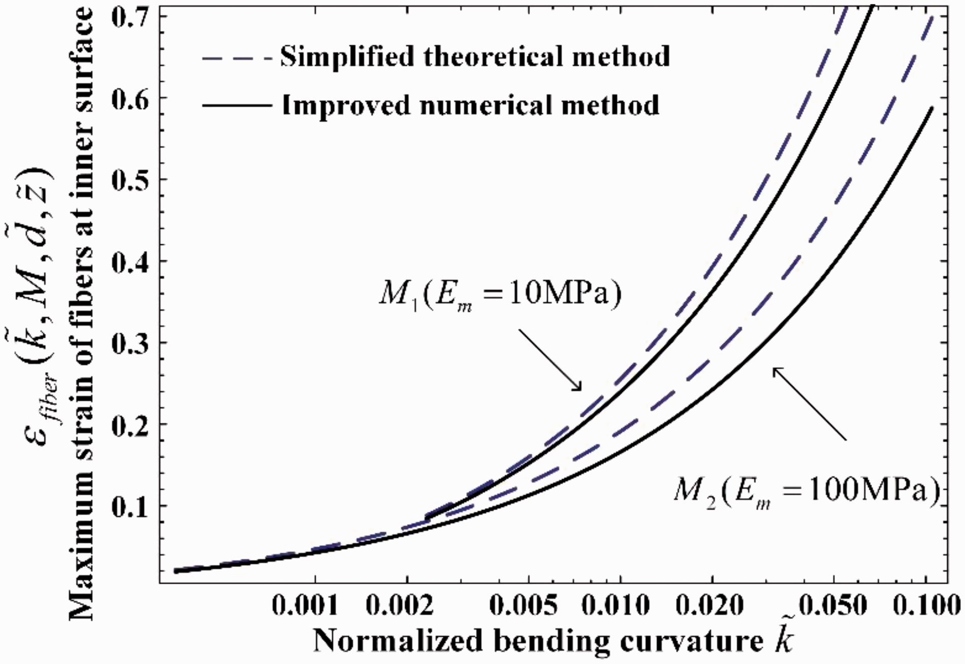
The strain of fibers
The relative low elongation at break for carbon fibers (i.e. 1.3–2.0%) disables the large reversible deformation for a FRSC. When considering stretching strain state of a FRSC, the elongation at break of fibers is at the same level with convenient fiber-reinforced plastics. On the other hand, when considering macroscale compressive strain state, the sinusoidal microbuckling configuration enables large amplitudes of fibers, but the strain of fiber themselves is still at a quite low level. As shown in Figure 11, the strain of buckled fibers rises along with increasing macro bending curvature. The maximum local strain of fibers at the normalized curvature is approximately 0.5–0.6%, which is around 1/20 of macroscale compressive strain (9–10%) for the FRSC; hence, this is the remarkable point of fiber local microbuckling.
The maximum strain of buckled fibers themselves at the inner surface (; fiber diameter d = 7 µm; thickness t = 0.1 mm; .
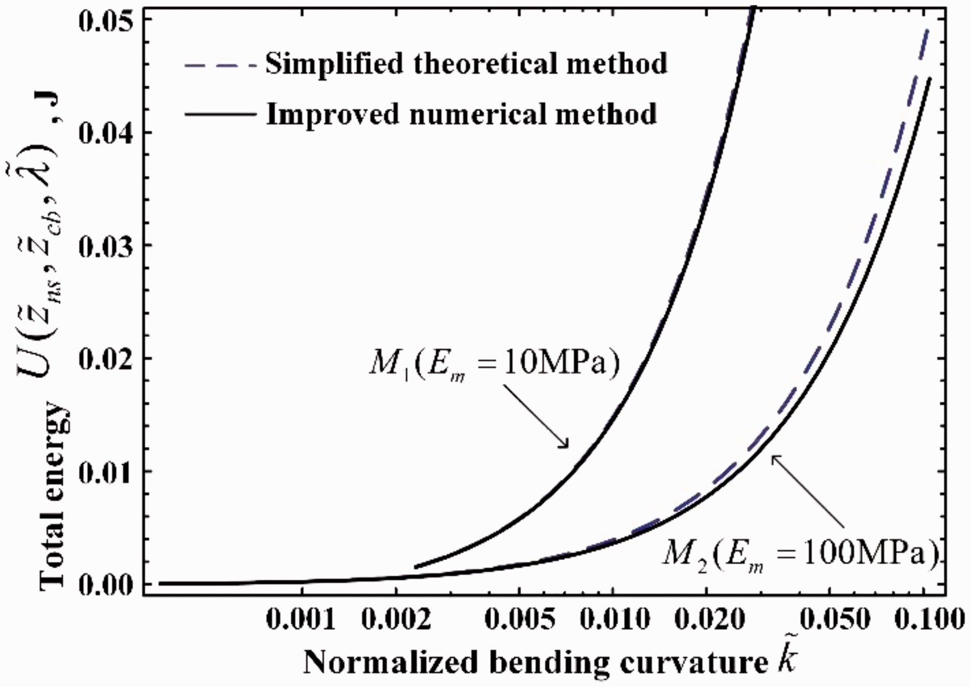
The total energy U and the actuation moment T
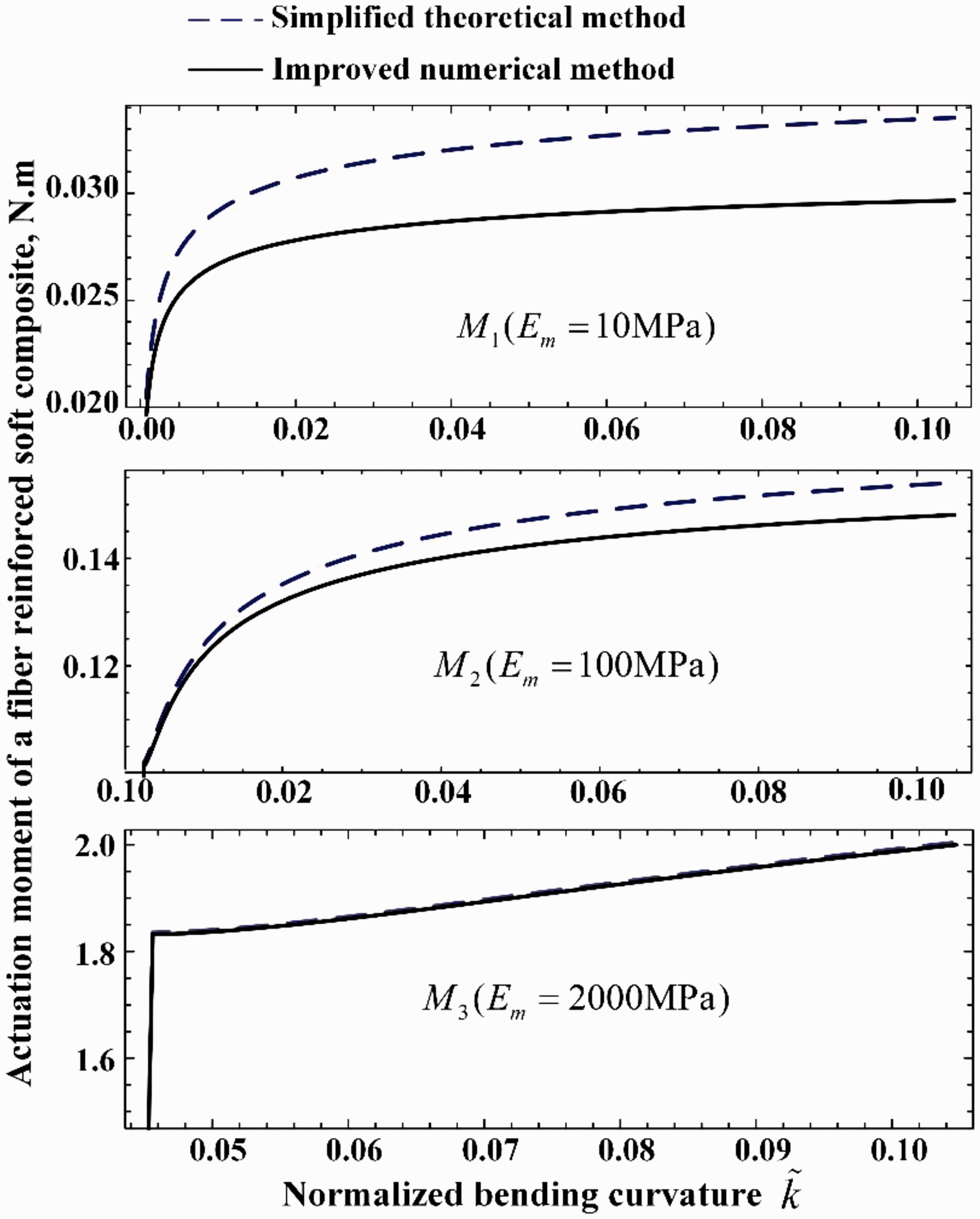
According to equation (2), are shown in Figure 12 using afore normalized parameters. The difference of results between the two methods excites and it becomes narrower when the composite coefficient M increases. According to equation (23), actuation moment can be derived and calculated (Figure 13). Considering shape-memory recovery process of a SMPC from large curvature to small curvature, actuation moment decreases slowly until the normalized bending curvature reduces to about 0.02. When smaller than this critical value, the actuation moment will sharply decrease to zero. With prediction of equation (23), the recovery performance of SMPC and their structures can be accurately designed, which is helpful to apply them in deployable structures in space.
The total strain energy .
The actuation moment of a fiber-reinforced soft composite laminate.
An example of macroscale bending large-deformation and microbuckling
From Figures 3 to 13 in the aforementioned section, the general regulation of macroscale bending large-deformation and associated microbuckling has been obtained in normalized form. For further discussion, considering typical geometrical and material property parameters (l = 30 mm, w = 5 mm, t = 1 mm, vf = 40%, d = 7 µm, h = 9.81 µm, Em = 15 MPa, Gm = 15 MPa, Ef = 230 GPa, and kc = 0.13 m–1), Table 2 lists result comparison between simplified theoretical method and improved numerical method of a FRSC at varied curvature k in dimensional forms. Evolution trend is correlated with analysis in the aforementioned section. For the FRSC (thickness t = 1 mm) at the curvature 100 m–1 (i.e. bending radius 10 mm), the maximum macroscale compression strain on the inner surface ( plane, z = 0) is as high as 10% associated with low compression strain around 0.4% of the fibers themselves in buckling configuration, which is the secret for a FRSC to obtain a large macroscale strain without microscale fibers failure.
Results comparison between simplified theoretical method (T) and improved numerical calculation (N) of a FRSC at varied curvature k with typical geometrical and material property parameters (l = 30 mm, w = 5 mm, t = 1 mm, vf = 40%, d = 7 µm, h = 9.81 µm, Em = 15 MPa, Gm = 15 MPa, Ef = 230 GPa, and kc = 0.13 m–1).
k,m–1
1
5
20
50
100
T
N
T
N
T
N
T
N
T
N
zns,mm
0.7752
0.7343
0.8921
0.8715
0.9445
0.9334
0.9645
0.9573
0.9748
0.9695
zcb,mm
0.71
0.5356
0.8791
0.7711
0.9412
0.8736
0.9632
0.9141
0.9741
0.9358
λ,mm
1.4491
1.6263
1.3624
1.5871
1.3026
1.5506
1.267
1.5242
1.2419
1.5039
Amax,mm
25.69
28.05
57.93
66.7
113.98
134.88
177.13
212.29
246.84
298.1
γxy,%
–5.57
–5.42
–13.36
–13.2
–27.49
–27.33
–43.92
–43.76
–62.44
–62.27
γyz,%
1.657
1.91
3.247
3.827
6.034
7.225
9.182
11.088
12.661
15.374
ɛxxC,%
–0.078
–0.073
–0.446
–0.436
–1.889
–1.867
–4.823
–4.786
–9.748
–9.695
ɛxxS,%
0.022
0.027
0.054
0.064
0.111
0.133
0.177
0.214
0.252
0.305
ɛf,%
–0.042
–0.034
–0.108
–0.079
–0.232
–0.164
–0.381
–0.263
–0.553
–0.377
U1, mJ
0.161
0.252
0.967
1.643
4.171
7.384
107.23
194.08
217.48
399.73
U2, mJ
0.119
0.079
0.894
0.621
4.386
3.011
12.087
8.21
25.7
17.314
FRSC: fiber-reinforced soft composite; xxC,: maximum compression strain on inner surface; ɛxxS: maximum stretching strain on outer surface; ɛxxS: maximum strain of fibers; (, U1): the value of using simplified theoretical method; (, U1): the value of using improved numerical method; (, U2): the value of using simplified theoretical method; (, U2): the value of using improved numerical method. The bold and underlined values are typical values of results comparison between T and N.
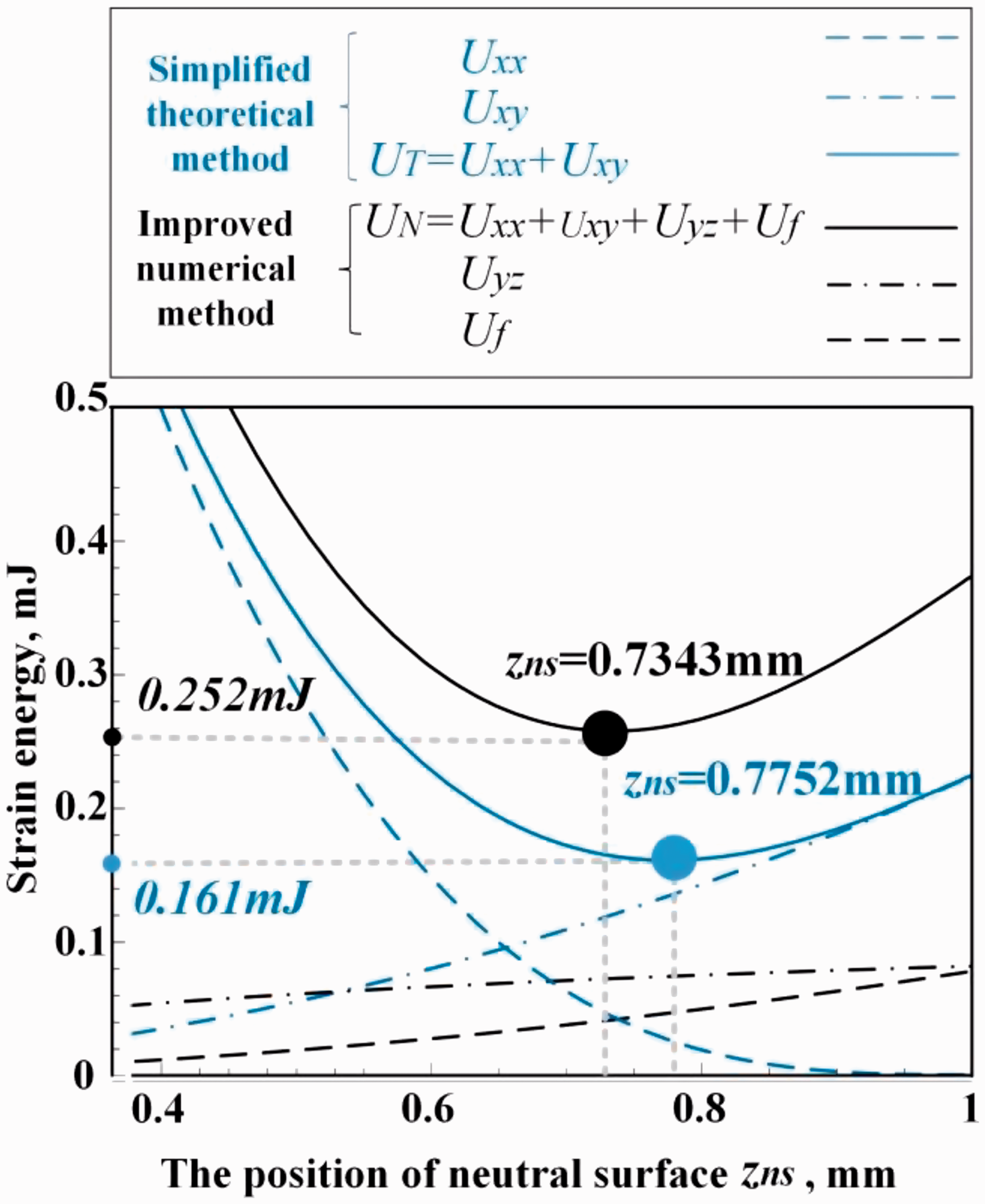
To explain the difference between simplified theoretical method and improved numerical method, a special case was selected to analyze the position of neutral surface at the curvature k = 1 m–1 (Figure 14). Considering the evolution trend, strain energy is monotonically decreasing. , , and Uf are all monotonically increasing. Furthermore, and are much higher than as well as Uf. The total strain energy of simplified theoretical method , and the total strain energy of improved numerical method . According to the minimum energy principle, the solved can be found at the lowest point of the strain energy curve as shown in Figure 14. UN has two more monotonically increasing terms (i.e. and Uf) compared with UT. Therefore, the value of longitudinal ordinate of UN curve is larger than that of UT at a certain . At the meantime, the value of horizontal ordinate of the lowest point of UN curve (0.7343 mm) is smaller than that of UT(0.7752 mm). That is to say, the solved , numerically calculating through the improved numerical method, is smaller than that derived by the simplified theoretical method. The difference of other parameters between simplified theoretical method and improved numerical method can be explained in the similar way according to the minimum energy principle.
Results comparison of strain energy terms between simplified theoretical method and improved numerical calculation of a FRSC at a curvature k = 1 m–1 with typical geometrical and material properties parameters.
When attempting to solve the equations only using the two terms through the minimums energy principle, it should be on the basis of the assumption is much smaller than . As shown in Figure 14, when the curvature k is large (k = 50 m–1 and k = 100 m–1), the ratio of the value of to is above eight (e.g. 217.48/25.7 for k = 50 m–1), which can be thought to meet the above demand. When the curvature k is small (k = 1 m–1, k = 5 m−1, and k = 20 m–1), the ratio of the value of to is around one (e.g. 0.161/0.119 for k = 1 m−1), which is difficult to satisfy the assumption. Consequently, the simplified theoretical method is mainly suitable to be used in large curvature condition.
Results and discussions
The expression of equation (2) gives the normalized form based on our previous study.39 The comprehensive regulation and the whole influencing parameters were not obtained in the previous study. In this study, the macroscale bending large-deformation behavior and the associated microscale fiber-buckling of a unidirectional FRSC are systematically discussed through the simplified theoretical method. The analytical expressions of key performance parameters including their influencing variable are first given out: normalized position of neutral surface , position of critical buckling , half-wavelength , normalized amplitude , shearing strain , shearing strain , macroscale compressive strain in buckling area, macro tensile strain in non-buckling area, strain of fibers , total strain energy U, and the actuation moment T.
When discussing the difference regularity between simplified theoretical method and improved numerical method, the simplified theoretical method only considers two terms , and the improved numerical method considers four terms . Those two more terms of the improved numerical method causes the difference when finding the solution according to the minimum energy principle. As shown in Table 2 and Figure 14, an example to compare the difference of between these two methods is discussed in detail. Furthermore, a systematical experiment is currently undergoing to validate the obtained results; the performance parameters of fiber microbuckling (e.g. wavelength and amplitude) are sensitive to the material and structural variables including matrix modulus, fiber fraction, and bending curvature. The experimental work and the related validation will be organized in the next paper in the near future. This paper is focused on the theoretical and numerical calculations.
For the simplified theoretical method, when attempting to solve the equations using the minimums energy principle, the logical reasoning was not strict enough. The self-consistent method was used on the basis of the assumption that should be much smaller than . However, as shown in the example (Table 2 and Figure 14), when the curvature is small, the above assumption cannot be satisfied well, and it is not strong enough to support the solving process for simplified theoretical method. In other words, that is the important role to use the improved numerical method to further pursuit the more accurate solution by employing the results of the simplified theoretical method as the initial calculating values. Therefore, these two methods should be used together to design a FRSC. The simplified theoretical method is employed to predict trend and obtain approximate results for a preliminary design; meanwhile, the improved numerical method will check and obtain more accurate results in the detailed design stage. The actuation moment of a FRSC laminate is first obtained in this study, which is important for shape memory FRSC using for space deployable structures.
Conclusions
To comprehensively describe the large-deformation behavior for a unidirectional FRSC, the expression of normalized average energy density was derived. By using a self-consistent approach and according to the principle of minimum energy, a series of analytical expressions were derived through the simplified theoretical method by solving a system with two terms of partial differential equations of average energy density. The analytical solutions in normalized expression clearly indicate influential factors and evolution trend, including position of neutral surface, position of critical buckling, wavelength, amplitude, shearing strain, macro compressive/tensile strain, buckled fiber strain, and actuation moment. An improved numerical calculation method was employed to numerically calculate the results of full terms (four terms) of partial differential equations of average energy density, using the results of simplified theoretical method (i.e. the normalized position of neutral surface and critical buckling, and the normalized half-wavelength) as the initial calculating values. The dimensionless results reveal that the trend correlates well between those two methods. The improved numerical method provides more accurate results than those of the simplified theoretical method. In summary, when using these two methods for designing a FRSC (e.g. SMPC used in space deployable structures), the simplified theoretical method could predict trend and approximate results for a preliminary design, and the improved numerical method could check and amend the results in detailed design stage.
Declaration of Conflicting Interests
The author(s) declared no potential conflicts of interest with respect to the research, authorship, and/or publication of this article.
Funding
The author(s) disclosed receipt of the following financial support for the research, authorship, and/or publication of this article: This work is supported by the National Natural Science Foundation of China (grant numbers: 11872020, 11632005, U1637207, and 11772109).
References
1.
TalrejaR. Assessment of the fundamentals of failure theories for composite materials. Compos Sci Tech2014; 105: 190–201.
2.
ZhuangLTalrejaR. Effects of voids on postbuckling delamination growth in unidirectional composites. Int J Solids Struct2014; 51: 936–944.
3.
RogersJASomeyaTHuangY. Materials and mechanics for stretchable electronics. Science2010; 327: 1603–1607.
4.
LiuQNianGDYangCH, et al.Bonding dissimilar polymer networks in various manufacturing processes. Nat Commun2018; 9: 846–846.
5.
HwangSWHuTKimDH, et al.A physically transient form of silicon electronics. Science2012; 337: 1640–1644.
6.
ZhangXSZhangYHLinJ, et al.Soft microfluidic assemblies of sensors, circuits and radios for the skin. Science2014; 344: 70–74.
7.
YangDVermaMSSuoZG, et al.Buckling pneumatic linear actuators inspired by muscle. Adv Mater Tech2016; 1: 1600055–1600055.
8.
YangDMosadeghBSuoZG, et al.Buckling of elastomeric beams enables actuation of soft machines. Adv Mater2015; 27(41): 6323–6327. DOI: 10.1002/adma.201503188.
9.
MorelleXBaiRSuoZG. Localized deformation in plastic liquids on elastomers. J App Mech2017; 84: 101002–1.
KimJYoonJHaywardRC. Dynamic display of biomolecular patterns through an elastic creasing instability of stimuli-responsive hydrogels. Nat Mater2010; 9: 159–164.
12.
ShengXZhengYKyung-InJ, et al.Assembly of micro/nanomaterials into complex, three-dimensional architectures by compressive buckling. Science2015; 347: 154–159.
13.
KimJBKimPPegardNC, et al.Wrinkles and deep folds as photonic structures in photovoltaics. Nat Photonics2012; 6: 327–332.
14.
AgorasMLopez-PamiesOPonte CastanP. A general hyperelastic model for incompressible fiber-reinforced elastomers. J Mech Phys Solids2009; 57: 268–286.
15.
Lopez-PamiesOIdiartMI. Fiber-reinforced hyperelastic solids: A realizable homogenization constitutive theory. J Eng Math2010; 68: 57–83.
16.
JiménezFL. On the isotropy of randomly generated representative volume elements for fiber-reinforced elastomers. Compos Part B-Eng2016; 87: 33–39.
17.
MichailidisPATriantafyllidisNShawaJA, et al.Superelasticity and stability of a shape memory alloy hexagonal honeycomb under in-plane compression. Int J Solids Struct2009; 46: 2724–2738.
18.
MichelJCPamiesOLPonte CastaedaP, et al.Microscopic and macroscopic instabilities in finitely strained fiber-reinforced elastomers. J Mech Phys Solids2010; 58: 1776–1803.
19.
LignonETallecPLTriantafyllidisN. Onset of failure in a fiber reinforced elastomer under constrained bending. Int J Solids Struct2013; 50: 279–287.
20.
TallecPBoussettaRLignonE. An enriched model of fiber reinforced thin flexible structures with in plane buckling capabilities. Int J Numer Meth En2012; 91: 872–895.
21.
JiangHQSunYGRogersJA, et al.Post-buckling analysis for the precisely controlled buckling of thin film encapsulated by elastomeric substrates. Int J Solids Struct2008; 45: 2014–2023.
22.
GuoZYPengXQMoranB. A composites-based hyperelastic constitutive model for soft tissue with application to the human annulus fibrosus. J Mech Phys Solids2006; 54: 1952–1971.
23.
PengXQGuoZYMoranB. An anisotropic hyperelastic constitutive model with fiber-matrix shear interaction for the human annulus fibrosus. J App Mech2006; 73: 815–824. DOI: 10.1177/0021998319854145.
24.
GeymonatGMullerSTriantafyllidisN. Homogenization of nonlinearly elastic-materials, microscopic bifurcation and macroscopic loss of rank-one convexity. Arch Ration Mech An1993; 122: 231–290.
LengJSLanXLiuYJ, et al.Shape memory polymers and their composites: Stimulus methods and applications. Prog Mater Sci2011; 56: 1077–1135.
27.
LiuYJDuHYLiuLW, et al.Shape memory polymers and their composites in aerospace applications: A review. Smart Mater Struct2014; 23: 023001–023001.
28.
RahmanAAIkedaTSenbaA. Memory effects performance of polyurethane shape memory polymer composites (SMPC) in the variation of fiber volume fractions. Fiber Polym2017; 18(5): 979–986.
29.
TakedaTNaritaFShindoY. Failure of hybrid beams consisting of woven carbon fiber composite and shape memory polymer layers under flexural loading. J Sandw Struct Mat2016; 18(1): 113–128.
30.
LanXWangXHLiuY, et al.Fiber reinforced shape-memory polymer composite and its application in a deployable hinge. Smart Mater Struct2009; 18: 024002–024002.
31.
ParkHHarrisonPGuoZY. Three-dimensional constitutive model for shape memory polymers using multiplicative decomposition of the deformation gradient and shape memory strains. Mech Mater2016; 93: 43–62.
32.
GeQLuoXRodriguezED, et al.Thermomechanical behavior of shape memory elastomeric composites. J Mech Phys Solids2012; 60: 67–83.
33.
Francis WH, Lake MS, Schultz MR, et al. Elastic memory composite microbuckling mechanics: Closed-form model with empirical correlation. In: 48th AIAA/ASME/ASCE/AHS/ASC Structures, Structural Dynamics, and Materials Conference, Honolulu, Hawaii, 2007, paper no. AIAA 2164, pp. 1–16. American Institute of Aeronautics and Astronautics.
34.
JiménezFLPellegrinoS. Folding of fiber composites with a hyperelastic matrix. Int J Solids Struct2012; 49: 395–407.
35.
JiménezFLPellegrinoS. Constitutive modeling of fiber composites with a soft hyperelastic matrix. Int J Solids Struct2012; 49: 635–647.
36.
WangZDLiZFXiongZY, et al.Theoretical studies on microbuckling mode of elastic memory composites. Acta Mech Solida Si2010; 23(1): 20–28.
37.
ZhangJMDuiGSLiangXY. Revisiting the micro-buckling of carbon fibers in elastic memory composite plates under pure bending. Int J Mech Sci2018; 136: 339–348.
38.
Murphey TW, Francis W, Davis B, et al. High strain composites. In: 2nd AIAA Spacecraft Structures Conference, AIAA SciTech, Kissimmee, Florida, 2015, paper no. AIAA 0942. American Institute of Aeronautics and Astronautics.
39.
LanXLiuLWLiuYJ, et al.Post microbuckling mechanics of fiber-reinforced shape-memory polymers undergoing flexure deformation. Mech Mater2014; 72: 46–60.