






Abstract
Aerospace composite material components are currently joined using heavy titanium bolts. This joining method is not ideal when considering its weight, thermal expansion, electrical conductivity, and risk of unbalanced load distribution. We propose here an innovative fastening technology using thermoplastic composite rivets. A rivet blank is heated above its melting temperature using Joule heating and is formed directly in the composite laminates by an automated process. Carbon fiber and polyamide blanks were used with two fiber architecture: 2D braid and unidirectional. The braided architecture showed superior manufacturing performance and repeatability. Joints were riveted in less than 40 s per rivet. The temperature measured in the riveted composite laminate in the vicinity of formed rivet reached only 136℃ during riveting. Double fastener lap shear testing showed breaking load of 6146 N per fastener. This joint strength is higher than comparable aluminum-riveted joints, and the specific joint strength is higher than titanium-bolted joints. With these advantages, the technology could be developed and used in the next generations of lighter, cleaner, and safer aircraft.
Introduction
Current joining methods for carbon fiber-reinforced composites (CFRPs) increase the components' design complexity and decrease their mechanical properties in comparison with an integrated part without joints.1–5 However, load-bearing joints remain mandatory due to limitations of the manufacturing processes, the necessity to disassemble to inspect, the repairability, and the transportation between manufacturing and assembly sites. Adhesive bonding is challenging to control in an industrial environment due to the presence of contaminants, the process' long curing cycles time, the impossibility to be disassembled without damaging the adherends, and the difficulty to be inspected.2,3,6 Therefore, metallic mechanical fasteners are widely used despite their many disadvantages.1,2,3,6 For instance, they have different thermal expansion coefficients from the surrounding CFRP structure, they can generate galvanic corrosion due to the material dissimilarity, and they are heavy. Mechanical fasteners are installed in drilled holes that weaken the structure. Their higher conductivity compared to the composite structure makes the metallic fastener a preferred electrically conductive pathway towards the inside of the aircraft in the event of a lightning strike, which could lead to potential safety threats. For that reason, metallic fasteners nuts located inside the structure must be encapsulated into insulating sealant caps that increase the weight of the aircraft. 7
The lack of ductility of CRFP is also problematic for fastening. When composite materials are exposed to localized limit loads, they cannot deform plastically near the application point while still maintaining the integrity of the structure; they will instead suffer microcracking and delamination.1,3,8 Therefore, drilling accuracy and precision must be very high to ensure that the load is well distributed across all fasteners of a joint. Unbalanced loading can lead to the premature failure of the structure. Force fit is not allowed because the friction forces can cause delamination damage in the composite at fastener insertion, nor is a loose fit allowed since it could create an unbalanced load distribution between fasteners of the same joint.1,3,8,9
Manufacturing processes were recently developed to join two CFRP laminates using continuous carbon or glass fiber-reinforced thermoplastic composite (TPC) rivets.10–12 These rivets could take advantage of the favorable properties of aerospace grade TPCs such as high moisture resistance, high impact resistance, low flammability, and infinite shelf life.2,13–15 The riveting processes deform a TPC cylindrical rod, i.e. a rivet blank, directly in the components, after heating the blank's thermoplastic (TP) resin above its melting point. The process temperature (T p ) must be as high as possible to lower the TP melt viscosity.
To reach these forming temperatures, it is possible to use heated tooling that transfers heat to the rivet blank through contact surfaces.10,12 Using this approach, Ueda et al. formed a rivet in 45 min. The heating time to reach 265℃ was 15 min, followed by a 30 min cooling time. 12 Another approach available is to use carbon fiber as a heating element. This method, referred to as Joule heating, was used for TPC resistance welding.2,6,13,16–19 A current is applied to TP preimpregnated carbon fiber UD or weaves placed between the two laminates. The heat generated is primarily attributed to the carbon fiber's electrical resistance property. Note that the carbon fiber's resistance can decrease by up to 16% when heated to 340℃.2,16,20 Moreover, fabric heating elements tend to have a better temperature distribution than a unidirectional (UD) heating element. 16 An electrical junction to the carbon fibers is also required. It is recommended to use a clamping pressure between the heating element and the electrodes to help minimize the contact resistance.2,16,18 It was observed that clamping the electrical wires directly to an impregnated heating element produced a poor electrical junction and a non-uniform heating.2,14,18 Whenever possible, clamping directly onto bare fibers is recommended using a pressure between 4 and 20 MPa.2,13,16 The welding intensity can be characterized by the surface power density (SP d ), which is the electrical power delivered by the source in a heating element per unit area. The selected SP d must lie between characterized limits for the welded materials and weld configuration. In general, a low SP d and a long process time will create undesirably high heat dissipation in the laminates. High SP d creates high-temperature gradients in the heating element and a higher risk of polymer degradation.2,13,16,21 Ageorges et al. 16 used polyetherimide (PEI) impregnated carbon fiber fabric heating elements to weld lap shear joints of glass fiber/PEI laminates. The applied SP d was 102.7 kW/m2. Hou et al. 13 used a similar heating element to weld lap shear joints of carbon fiber/PEI laminates. The heating element thickness was around 0.7 mm, and the SP d applied was 118 kW/m2. In these two cases, the volumetric power density (VP d ) delivered to the heating element was approximately 170 MW/m3.
High forming temperatures can possibly affect the joined CFRP materials made with thermoset polymers. If exposed to temperatures higher than their glass transition temperatures (T g ) for a specific time, their mechanical properties can significantly decrease.22,23 Therefore, any local heating of CFRP must minimize the size of the heat affected zone (HAZ). During resistance welding, it has been observed that the HAZ around the heating elements can affect the joined laminates' properties. It is recommended to keep this zone as close as possible to the heating elements.2,17,22 Pouliot Laforte et al. have simulated a TPC-riveting process by inserting a cylindrical heating element in a drilled aerospace grade carbon/epoxy laminate. They have exposed the hole surface to various process temperatures according to the following cycle: a heat ramp of 60 s, a temperature hold of 30 s, and subsequent cooling. No significant drop in the laminate bearing strength was observed even if the heated cartridge surface reached 360℃. This study indicates that quick exposures at temperatures higher than the joined laminate's T g is possible without affecting fastener-bearing properties of the laminate. 24
The rivet blank is a TPC rod cut to a specific length. This rod can be pultruded from a commingled yarn precursor.18,19,25–30 Commingled yarns contain an intimate mix of carbon fibers and TP polymer filaments. Pultruded rods are usually composed of UD fibers that are manufactured by pulling straight commingled fibers into a pultrusion apparatus.19,26,28,29 The commingled fibers can also be braided in order to change the mechanical properties of the pultruded rod.25,30 In this case, the rod's shear strength and stiffness will increase due to the braided fiber arrangement.25,31,32 By intertwining the yarns, the braiding process orients the fibers along a certain angle, i.e. the braid angle, with respect to the braid's longitudinal direction. The axial distance taken by yarns to complete a revolution around the central axis is called the braid pitch. A regular braid is created when each yarn goes over and below two yarns. The relation between the braid angle, pitch, and diameter is defined as
The above reviewed literature indicates that current TPC rivets are formed using external heating elements that extend the process time. Long process time increases heat-damage risks to the composite laminates to be joined. The main objective of this study was to develop a short TPC riveting process of CFRP structures using solely Joule heating of the rivet blank. The second objective was to investigate the effect of the rivet blank braided or UD fiber architecture on the process and mechanical performance. Rivet blanks were made by pultrusion. First, the riveting process was characterized. Then, the morphology of rivets was investigated. Finally, the lap-shear mechanical properties of riveted joints were measured and compared.
Material and methods
Riveting process
Figure 1 shows the riveting process sequence. Figure 1(a) presents the main tooling parts and the apparatus configuration before the beginning of the process sequence. The ram is actuated to form the blank while also being an electrode. The electrodes transfer the electrical power to the blank, which, in turn, generates heat by means of the Joule effect. The electrical source is controlled so that it delivers a constant electrical power. This approach is preferred to ensure a constant heat generation regardless of the blank fiber architecture and the resistance variation of the carbon fibers caused by temperature. The nature of the process only allows direct contact of the electrodes on the impregnated carbon fiber even though the risk of using non-uniform heating is higher than when using bare fibers.
14
Before the sequence starts, the blank is inserted directly in the CFRP laminates between the electrodes. The bucking tool is completely inserted into the bucking tool socket. The bucking tool is held in place using the electromagnets that resist the opening force applied by the compression springs.
Riveting process sequence (a) main tooling parts, (b) CSKH formation step, (c) bucking tool opening step, and (d) CYLH formation step.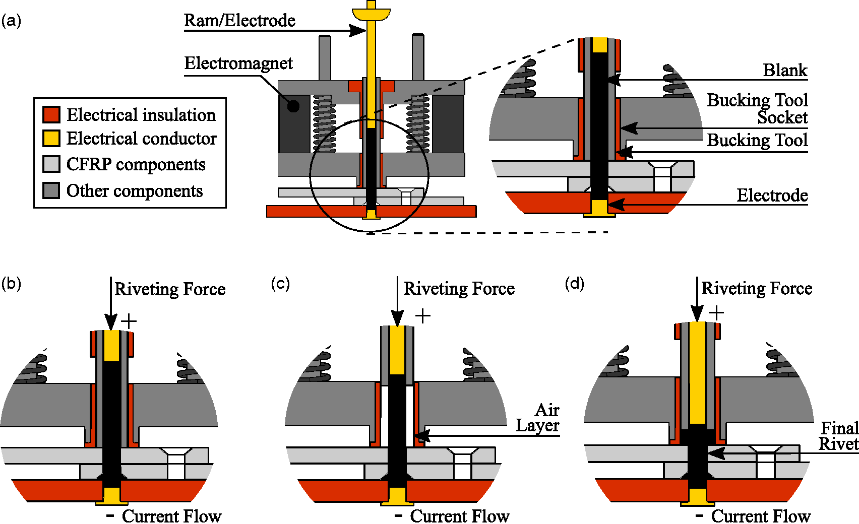
The countersunk head (CSKH) formation step is shown in Figure 1(b). The riveting force is applied when the resistance heating starts. The resistance heating and the riveting force are maintained throughout the sequence. As soon as the matrix melts and its viscosity drops, the ram moves down to keep the force constant. During this step, the mold cavity, defined as the conical shape which is made by the countersink drilled into the laminates, is filled with the melted blank. Once the melted blank fills the countersink cavity, the heat transfer from the rivet to the laminates increases. This reduces the heat accumulation in the CSKH even if Joule heating is on. Figure 1(c) presents the opening step of the bucking tool. After a predetermined CSKH forming time, the electromagnets are switched off. The springs push the bucking tool away from the joint. The bucking tool slides into the bucking tool socket to create an air layer around the blank. This air layer is an effective insulator, which helps concentrate heat generation in the blank at the cylindrical head (CYLH) level. During the final step, shown in Figure 1(d), the ram, in conjunction with the bucking tool, is pushed down on the melted blank to form the CYLH. During this step, the mold cavity is produced by the cylindrical shape of the bucking tool socket's surface. After a predetermined time of CYLH formation, the resistance heating is stopped. The riveting force is maintained to avoid deconsolidation until the TP cools below the T g . Heat is flown out of the rivet through the tooling and laminate surfaces in contact with the rivet material. The tooling is opened, and the riveted joint is complete.
The CSKH formation time and power were fixed to, respectively, 30 s and 120 W based on unpublished preliminary studies. For the CYLH, the formation time and power were decreased to 10 s and 90 W. Since the blank is already at a high temperature after the CSKH formation, it is not necessary to provide the same amount of energy for the CYLH formation. The force applied throughout the complete rivet forming was 200 N. This force corresponds to a pressure of 10 MPa on the surface of the blank cross section.
Materials, blank manufacturing, and rivet geometry
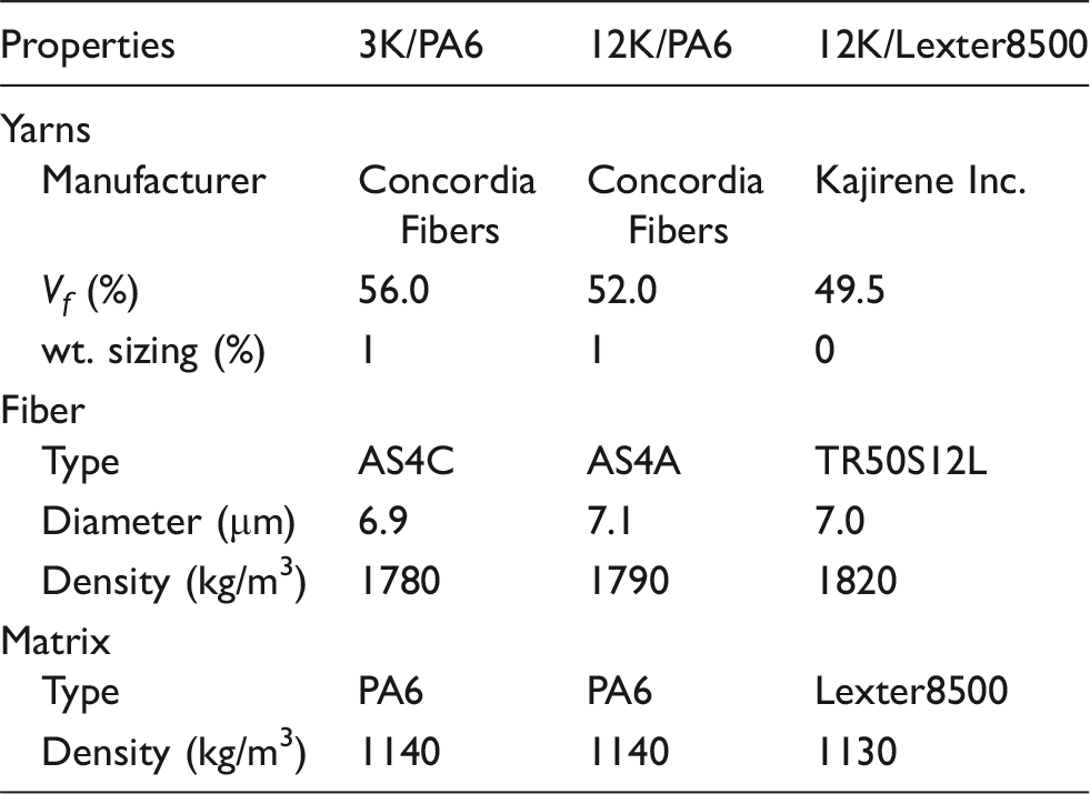
Commingled yarns manufacturer properties.
Pultrusion process parameters.
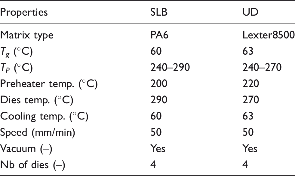
Figure 2(a) shows the SLB blank's typical dimensions. The UD blank had the same dimensions except for the pitch, which is not applicable. The nominal blank's diameter (d
b
) and length (L
b
) were 4.8 and 45 mm, respectively. Figure 2(b) shows the double fastener lap shear coupon configuration and dimensions. This coupon geometry is in accordance with aerospace test standard NASM1312-4. Two fasteners were riveted into the CFRP laminates from opposite directions. CFRP laminates were made of 8HS/Epoxy (CYCOM 5276-1 from CYTEC Solvay Group) prepreg with a [0/45]3S stack up. The laminate thickness was 5.1 mm to limit bending deformation during shear testing that give rise to out-of-plane loads. The laminates were cured in an autoclave in accordance with the manufacturer's recommendation. The epoxy T
g
was 188℃. Figure 2(c) shows a schematic of the SLB rivet having two different rivet heads. One is a CSKH and the other is a CYLH. The rivet geometry was selected in accordance with aluminum aerospace grade solid rivet with a CSKH angle of 100°. This aluminum rivet is traditionally used in aluminum airframes. The rivet shank diameter was 5.0 mm, corresponding to the lap shear coupon holes (see Figure 2(b). The 2.4 mm extra length on each side was added to help the blank alignment in the riveting tool. Moreover, this minimizes slippage of fibers during the riveting process. After the process, the overall rivet length (L
r
) is approximately 20 mm. Figure 2(d) shows the position of the thermocouple used to measure the evolution the joint temperature during riveting. The temperature was measured in one CFRP joint with a J-type thermocouple. The thermocouple was inserted in a small hole (dia. 1.5 mm) drilled between the CFRP laminates as close as possible to the rivet shank.
Schematics showing typical geometries and dimensions (in mm). (a) Braided blank where d
b
is the blank diameter, L
b
is the blank length, and P
b
is the braid pitch. (b) NASM1312-4 double fastener single lap shear coupon. (c) Braided rivet formed with the riveting setup into the lap shear coupon shown in (b). L
r
is the total rivet length. (d) Location of the thermocouple insertion for measurement of the temperature during riveting.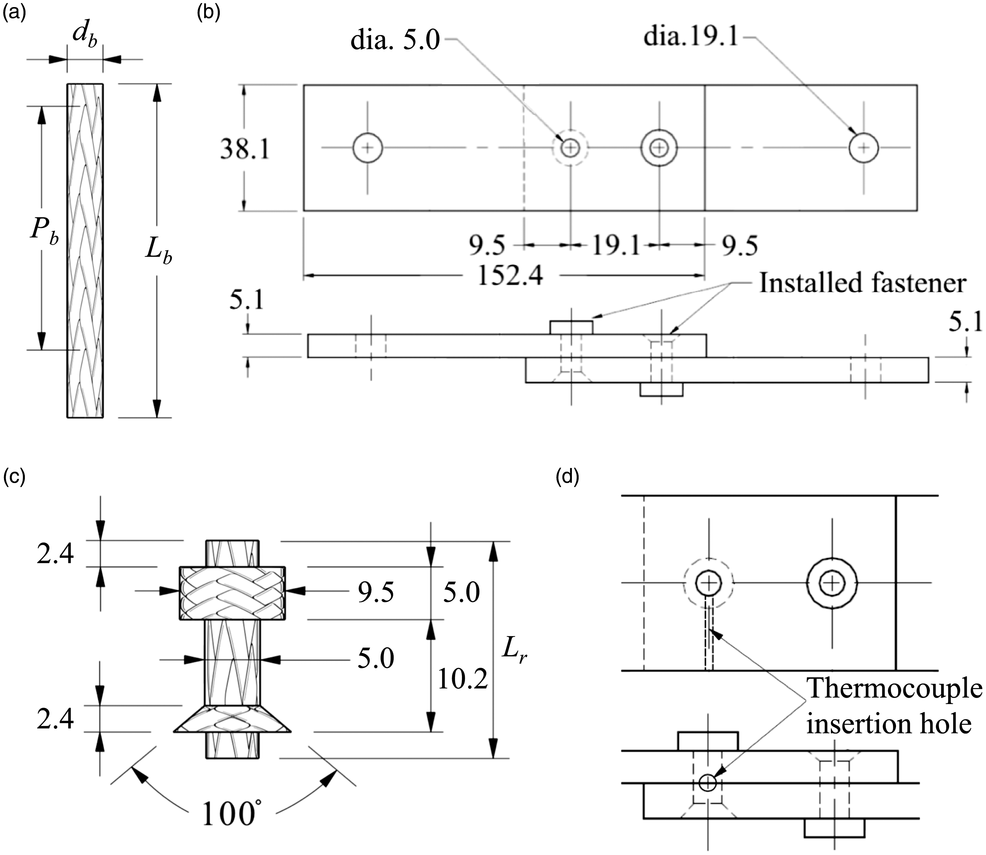
Riveting machine setup
An automated riveting machine was designed and manufactured to perform the process described in the section “riveting process”. The ram was made of tool steel owing to its good wear resistance and electrical conductivity. The bucking tool was made of alloy steel. A nylon sleeve was used as an electrical insulation barrier between the bucking tool and the machine. The bucking tool socket was made of Rulon J polymer to provide both insulation and resistance to high temperature. The base was made of high temperature fiberglass composite specified to MIL-I-24768/3 and NEMA G-11. This base was electrically and thermally insulated to help the heat generation during the CSKH heating step. The electrode in the base was made of brass.
The riveting force was applied using a linear actuator (KK6010P200A1F1CS200; Hiwin) that has a maximum force of 200 N. The precision of the applied force was characterized within 1 N of the set point. The electrical power for Joule heating of the blank was generated using an adjustable power supply, supplying a maximum of 15 V and 60 A (1902B, BK Precision). The power was controlled in a closed loop by adjusting the current limit in accordance with the measured voltage. The power given by the source is assumed to be completely converted into heat. The ram displacement, the riveting force, the voltage supplied, and the joint temperature were logged with a data acquisition unit (U6; Labjack) and LabVIEW (National Instrument).
Characterization
The riveting process performance (P
r
) was characterized by its capacity to fill the countersunk hole and tooling cavities completely when shaping the blank into a rivet. Assuming that the blank volume is equal to the rivet volume, the performance is defined as
Mechanically fastened joint design is mainly based on statistical values derived from test results, called allowables.1,3,33 Test standards and allowables were developed in order to have sufficient safety margins, while reducing joint weight and increasing cost-effectiveness.1,3 Each material and joint configuration has its own allowable. In order to compare TPC-riveted joints with other configurations' allowables, 33 the ultimate single lap joint shear strength was measured according to the NASM1312-4 standard (see Figure 2(b)). Three samples were tested for each configuration using a universal tensile testing machine (MTS; Insight) equipped with a 50 kN load cell. A constant displacement rate of 0.5 mm/min was applied.
Results and discussions
Blank manufacturing
Blank dimensions.
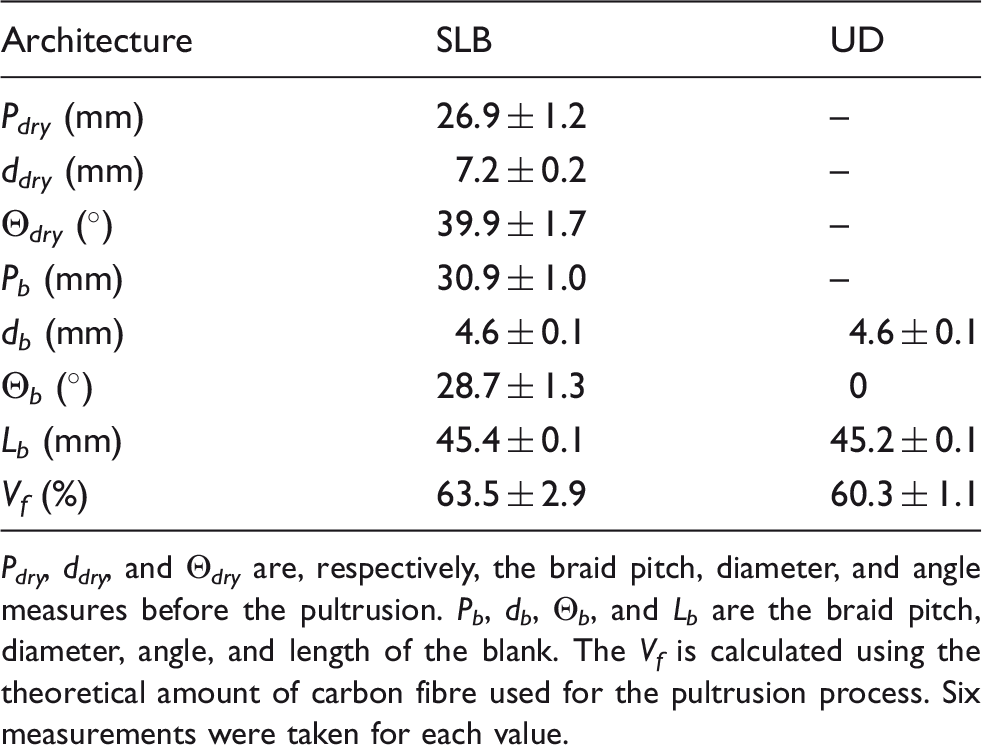
P dry , d dry , and Θ dry are, respectively, the braid pitch, diameter, and angle measures before the pultrusion. P b , d b , Θ b , and L b are the braid pitch, diameter, angle, and length of the blank. The V f is calculated using the theoretical amount of carbon fibre used for the pultrusion process. Six measurements were taken for each value.
Process behavior
An example of a rivet and a riveted joint are shown in Figure 3(a) and (b). The riveting process behavior is described in Figure 4. Figure 4(a) is a reminder of nominal process parameters. A constant force of 200 N was applied during the process. The electrical power was set to 120 W during the 30 s of the CSKH formation. It was decreased to 90 W for the last 10 s of CYLH formation. The graph in Figure 4(b) shows the evolution of the performance, calculated according to equation (2), with respect to riveting time. The error bars are standard deviations from an average of six rivet formation for each architecture. When the process started, the ram quickly began to move. This indicates a rapid heating of the blank to melt the rivet TP matrix. The time at which the process performance reached 43% for the CSKH forming and 100% for the CYLH forming, was identified and reported in Table 4. The SLB rivet deformed and filled the CSKH in 20.4 ± 4.7 s. The UD rivet reached the 43% performance value for full CSKH forming at 26.9 ± 6.5 s. In some cases, the UD rivet CSKH head could not be completely formed before the bucking tool's opening at approximately 30 s. The shorter formation time for the SLB rivet is probably due to the improved temperature distribution that can be generated in textile heating elements, as mentioned in Ageorges et al.
16
It is seen in Figure 4(b) that the CYLH formation after bucking tool opening started at 30 s with a sudden increase in the performance slope. It must be noted that the bucking tool opening was triggered manually with possible short delays. This explains the wide standard deviation on process performance calculated at 30 s in Figure 4(b). An example of performance curves for one SLB and one UD rivet are presented in Figure 4(c). Only the few seconds around the bucking tool nominal opening time is shown. The bucking tool opening for this specific SLB rivet was triggered slightly before the 30 s mark. For the UD rivet, the triggering happened more than 1 s after the same mark. In both cases, the CYLH head was formed in less than 1 s. This is indicated by the step from around 43% to more than 100% appearing in the performance curves in Figure 4(c). This process speed was possible since the blank was already hot when the bucking tool opened. Moreover, such fast forming pave the way for the reduction of the riveting process duration below 40 s. The process performance at the end of each step was measured and reported in Table 4. For the SLB and UD rivet, the performance at manual bucking tool opening was 87.7 ± 9.5% and 55.8 ± 33.9%. The averages exceeded the theoretical value of 43%. However, these results cannot be considered reliable due to the variability created by the manual triggering of the bucking tool. The final performance value at 40 s (total process time) exceeded 100%. This indicates that the process successfully formed the rivets into the countersunk hole and tooling cavity, and that some matrix flashing occurred.
(a) Example of UD rivet. (b) Example of CFRP-riveted joint. Both CSKH and CYLH are seen since the two rivets are installed from opposite directions, as per NASM1312-4. Parameters' evolution during the 40 s riveting process. Average values and standard deviations are based on six riveting sequences for SLB and UD. The vertical line in all graphs represents the nominal bucking tool opening time. (a) Representation of applied riveting force and applied electrical power. (b) Evolution of process performance (see equation (2)). Horizontal lines represent the ideal process performances for CSKH (43%) and CYLH (100%). (c) Close up view of the single SLB and UD blank riveting process performance around bucking tool opening, from 29 to 32 s. (d) The temperature measured in the laminates in comparison with the epoxy T
g
. Temperature was measured on only one riveting sequence for each blank type. (e) Variation of the electrical resistance. Measured riveting process parameters. All means and standard deviations measured using 6 rivets were used for each of the architectures, and one for the temperature.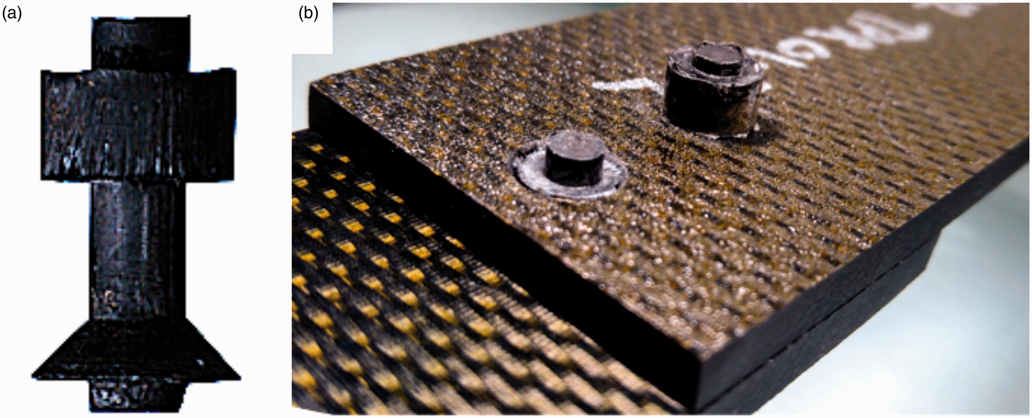
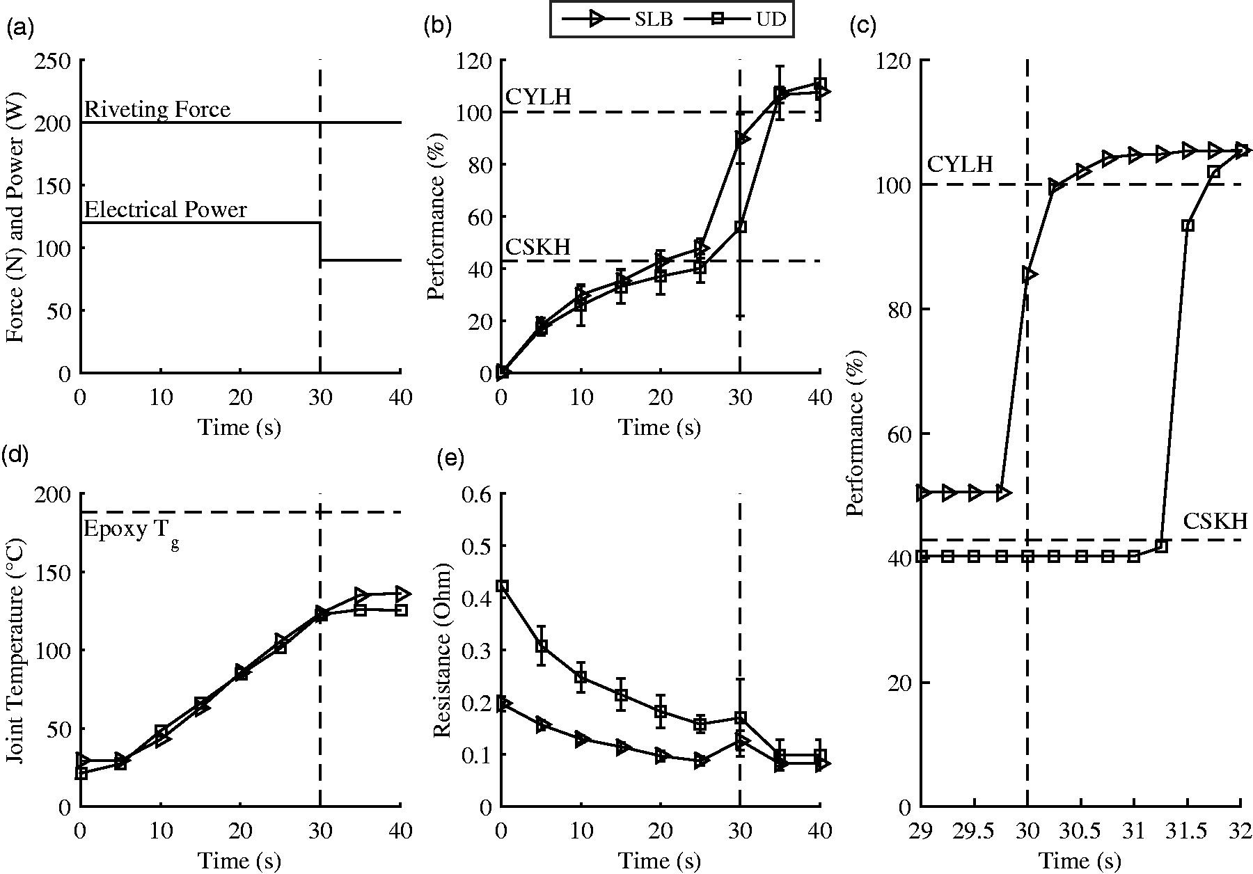
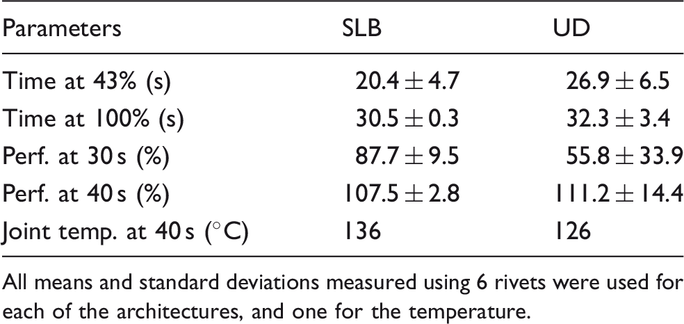
The laminate's temperature variation, measured at approximately 1 mm from the rivet's surface, is presented in Figure 4(d). Both slopes are similar due to the same dissipated power in the blank. In the last 10 s, after the bucking tool opening, the measured temperature in the SLB joint continued to increase at a slower rate while the temperature in the UD joint stabilized. This difference could be explained in further studies comprising bigger sample size. The maximum logged temperatures in the laminates are listed in Table 4. The joint temperature at 40 s was 136℃ for the SLB rivet and 126℃ for the UD rivet. These temperatures stay well below the epoxy T g of 188℃. It can be assumed that the HAZ is quasi-nonexistent. However, the exact temperature experienced by the joint hole surface in contact with the melted matrix could not be measured. This should be addressed in a separate detailed study.
The electrical resistance variation during the riveting process can be seen in Figure 4(c). The resistance values at process start were quite different for both architectures. The measured SLB blank resistance was 0.20 ± 0.01 ω, half of the measured UD resistance of 0.42 ± 0.01 ω. This difference is attributed to the different fiber architectures (SLB vs UD). Moreover, the different carbon fibers used for the two rivet types must have different intrinsic electrical resistances. During process evolution, it was observed that the UD blank resistance decreased by 70% and the SLB blank resistance by 59%. This substantial resistance variation highlights the importance of power control for Joule heating of the blank. The power is maintained to set point by adjusting the current applied according to measured blank resistance. Assuming that the electrical power is completely transformed in heat, constant electrical power guaranties constant heat generation. This allows reaching the process temperature at constant and repeatable rates, as seen in Figure 4(b). Under these conditions, the riveting process becomes predictable and repeatable. Another observation can be made since the resistance decrease was approximately one order of magnitude higher than the decrease of 6.3% to 16% observed at 340℃ by Stavrov et al. 2 Therefore, it is expected that other phenomena were responsible for this resistance drop. In the first 30 s, the electrical resistance reduction follows a trend opposite of the process performance seen in Figure 4(b). The process performance is inversely proportional to the rivet length reduction. During rivet forming in compression, it is assumed that fiber movement and fiber buckling created contacts between carbon fibers. This effectively reduced the electrical resistance of the blank. At around 30 s, when the bucking tool opened, it is seen that the resistance slightly increased. This variation is attributed to an increase of the contact resistance on the blank which is due to the reaction force of the springs. The final reduction in resistance from 30 to 40 s is also attributed to the reduction of the rivet length during CYLH formation.
According to the blank geometry, the Joule heating electrical power of 120 W corresponds to a volumetric power density of 160 MW/m3. This value is close to the volumetric power density of 170 MW/m3 taken from Hou et al. 13 This similarity must, however, be treated carefully since the thermal behavior of the riveted coupons was different from a lap shear joint welded in Hou et al.'s study. Further studies should characterize the actual temperature distribution within the rivet and joint during forming. This characterization could identify if hot spots are present giving rise to potential rivet polymer degradation. Possible mitigation strategies include different blank fiber architectures (e.g. triaxial braids, 3D braids). Moreover, different electrical power histories, such as pulsed current input, 2 could be tested to improve heating time while keeping acceptable temperature gradients.
Morphology analysis
Figure 5 shows cross section images of the blanks and rivets. The SLB blank, presented in Figure 5(a), shows yarns of carbon fibers intertwined together with some black spots indicating voids. Figure 5(b) shows the SLB rivet within the drilled laminates. Many yarn and fibers located in the CYLH and CSKH are oriented radially. This indicates an increase in braid angle due to compression deformation and increase in diameter. It is also seen that the SLB rivet shank has modified yarn orientations compared to the SLB blank. The yarns moved and no repeatable structure can be seen. Furthermore, Figure 5(b) shows that resin and fiber have flown into the hole drilled between the laminates. This hole used for thermocouple insertion is identified by a dashed line rectangle. This material flow indicates that the matrix melted in the shank during riveting. It denotes that this process can be used to deform the rivet shank to adapt to the drilled hole geometry. The UD blank, presented in Figure 5(c) shows straight fibers aligned along the blank axis. Again, black spots indicate voids that could not be removed during the pultursion process. Figure 5(d) shows the cross section of the rivet made with the UD blank. It is seen that the fibers are oriented randomly throughout the whole rivet cross section. This random orientation indicates fiber buckling during rivet formation in compression. The fiber buckling in the shank is another indication that the matrix melted at this location during forming for both SLB and UD rivet. Random fiber movement, and buckling, in the shank can be highly detrimental to the repeatably of the mechanical properties. Therefore, the process should limit as much as possible the fiber movement in the shank. This could be done by increasing shank diameter close to the drilled hole.
Blank and rivet morphologies. White scale bars are 2 mm. (a) SLB blank. (b) SLB rivet. The dashed line rectangle indicates the location of the thermocouple drilled hole. A slight flash of resin and fibers can be seen at hole end close to the rivet shank. (c) UD blank. (d) UD rivet.
Mechanical properties
Figure 6 presents the double fastener single lap joint mechanical characterization according to NASM1312-4 standard. Three joints were tested per rivet type (SLB and UD). Figure 6(a) shows the force evolution during the joint testing with respect to the cross-head's displacement. Note that the reported force is the measured force on the coupon divided by two to express the force per rivet. The initial load/displacement curves for SLB- and UD-riveted joints are superposed indicating similar stiffness for both architectures. At approximately 2000 N, a stiffness decrease is observed with a reduction of the slope of the force/displacement response. This is attributed to the onset of damage in the joint or fastener. It should be noted that the error bars are larger for the UD rivet than for the SLB rivet. This scattering in the results can be explained by two reasons: (i) the intensity of fiber buckling in UD shank is possibly more severe than in the SLB blank; (ii) the porosity in UD rivet could be higher or badly distributed compared to the SLB blank. More systematic porosity characterization should be made to verify these hypotheses. The UD rivet's breaking load of 6146 ± 471 N is significantly higher than SLB rivets' of 4712 ± 177 MPa. This result is counter-intuitive since the SLB's braided fibers are expected to improve shear properties.
31
Unfortunately, a proper explanation is difficult to find since the carbon fiber, the matrix, and the sizing are not identical between SLB- and UD-based rivets. Future investigation should be made to explain these results. Figure 6(b) and (c) shows close-up pictures of the broken SLB and UD rivets, respectively. In both cases, the broken rivet cross sections contain a net shear surface and some fiber pull-out. Finally, Figure 6(c) shows an ovalized hole in the laminate with some cracking. This indicates bearing failure in the laminates due to high rivet shear strength.
Double fastener lap joint shear test of TPC rivets according to NASM1312-4. (a) Force versus displacement curves. The force shown is for one rivet only. Error bars are calculated on an average of three tested coupons. (b) Shear failure of the SLB rivet. (c) Shear failure of the UD rivet. Holes on the laminate are slightly oval indicating bearing damage.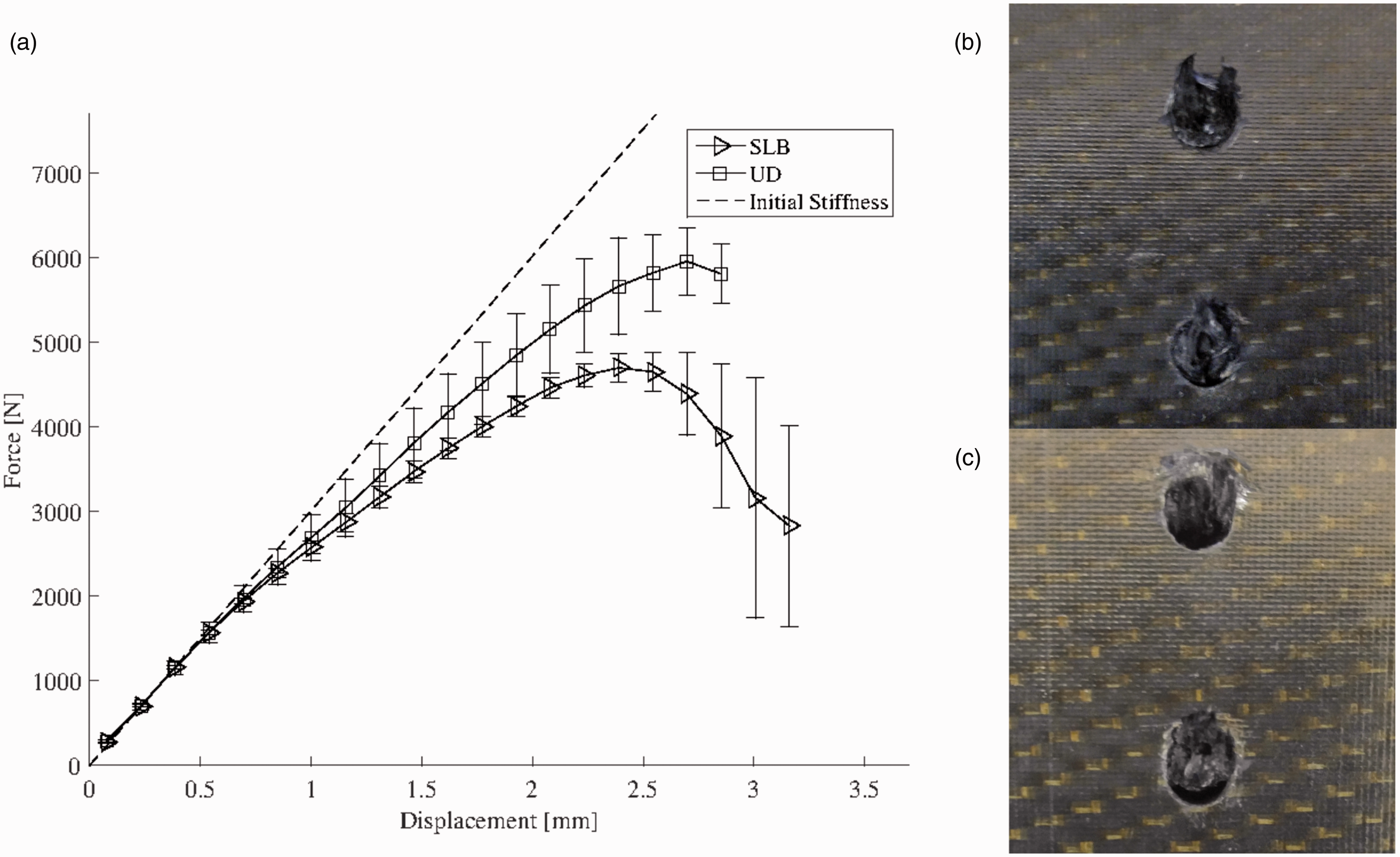
Static joint strength of 100° flush shear head of some aerospace grade fastener in a machine-countersunk sheet in comparison with the TPC-riveted joint.
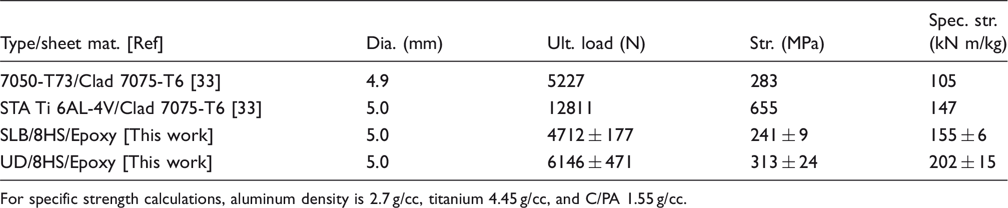
For specific strength calculations, aluminum density is 2.7 g/cc, titanium 4.45 g/cc, and C/PA 1.55 g/cc.
Conclusion
An innovative CFRP components joining method was developed using TPC rivets. The rivets blanks used were cylindrical CF/PA6 TPC rods having a diameter of 4.6 mm. The process starts with the application of constant power electrical current to generate heat in the cylindrical blanks by Joule heating. The riveting tooling and sequence are designed to generate heat in the CSKH first, followed by the CYLH. The formation of both heads is driven by a constant force applied throughout the whole process. The forming process duration is currently 40 s but could potentially be lowered with improved controls and tooling, as well as increased electrical power. SLB or UD rivet blanks were successfully riveted in carbon/epoxy composites. When using SLB blanks, the process variability was lower than when using UD blank. Mechanical properties were also more repeatable when using SLB blanks. However, the UD-riveted joint has shown the highest joint shear strength. The observed strength was compared with standard riveted and bolted joint mechanical properties. The shear strength of UD-riveted joints is higher than 7075-T73 rivet shear strength measured in similar conditions with aluminum adherends. Furthermore, specific shear strength of both SLB- and UD-riveted joints is higher than that of a similar titanium-bolted joint. In future studies, aerospace grade TP, such as PEI or polyether ether ketone (PEEK), will be tested for further improvement of the riveted joint resistance. While these TPs are processed at temperatures over 350℃, they are also known to be less sensitive to water absorption than PA6. Finite element modeling could be used as a tool to improve the fiber architecture design for better mechanical properties. For example, a tri-axial braid could be used to combine the higher apparent shear strength of the UD rivet to the manufacturing and strength repeatability of the SLB one. The technology demonstrated here opens new possibilities for the assembly of aircraft structures.
Footnotes
Acknowledgements
The authors would also like to acknowledge the contribution of Felix Lapointe and Felix Lessard for the pultruded blanks.
Declaration of Conflicting Interests
The author(s) declared no potential conflicts of interest with respect to the research, authorship, and/or publication of this article.
Funding
The author(s) disclosed receipt of the following financial support for the research, authorship, and/or publication of this article: The authors would like to thank Bombardier, Pultrusion Technique, NSERC (CRDPJ488387-15), and Prima Quebec (R10-009) for financing this research project.