
Abstract
In the present study, different stacking sequences on hybrid carbon/glass/epoxy composites laminate were examined in relation to thermal, dynamic mechanical and long-term behavior. A positive hybrid effect was found for both hybrid composites (interleaved-Hybrid 1 and in block-Hybrid 2) showing that in some cases hybrid composites can properly replace carbon or glass composites. The composite containing all glass fiber in the middle (Hybrid 2) presented similar thermal behavior when compared to glass fiber composite. All hybrid composites presented higher storage modulus when compared to glass composite. Dynamic mechanical analysis showed that both hybrids can satisfactorily perform the requirement in a wide temperature range. The long-term prediction was successfully applied for all composites, showing to be highly temperature-dependent. Hence, depending on the application requirement, both hybrids can be used, saving weight and cost.
Introduction
Carbon and glass fiber reinforced composites are being used for a long time as structural parts in automotive and military industries due to their high strength-to-weigth ratio, high specific stifness, low coefficient of thermal expansion, good fatigue life and high corrosive resistance.1–4 According to Das, 5 it has been estimated that the use of glass fiber reinforced polymer (GFRP) as structural components could yield 20–35% reduction in vehicle weight; more significantly, the use of carbon fiber reinforced polmeric (CFRP) matrix composites could yield 40–60% weigth reduction. While GFRP have been increasingly used to replace steel in automative industry, 6 the adoption for carbon fiber composites remains low, regarding the high cost of respective fibers. As a consequence, composites based on carbon fibers are popular in luxury and racing cars and aeroespace vehicles, for which additional payload capacity and engine efficiency are primary issues. Cost reduction is a continuous challenge facing automobile manufacturers while fuel economy and technology transformation are becoming more important.7,8
To further reduce vehicle weigth without excessive cost increase, one possible technique is to incorporate carbon fiber reinforcement into glass fiber composites in different stacking sequences.9–11 Hybrid composites are composed of more than one type of reinforcement in the same matrix system, which is classified into interply or laminated hybrid, intraply or tow-by-tow hybrid, intimately mixed hybrid and other types of mixtures. 12 Some of the influential factors affecting the composite mechanical performance from the reinforcement include fiber length, fiber orientation, fiber architecture and fiber material.13–15 Since mechanical properties of glass and carbon fiber composites differ greatly, it is expected that some specific properties could be controlled by properly selecting the reinforcement design (i.e. hybrid stacking sequence).16–19 The selection of the angle ply, type of fiber and fabric architecture depends on the specific application. 20 For example, the selection of cross-ply laminates consisting of layers oriented at 0°/90° laminates usually are studied for the crack propagation and its effect on the load capacity of laminated composites. 21
Sayer et al. 22 studied glass/carbon hybrid composites and the effects of temperature variation [from –20℃ to 60℃] on impact response of hybrid composites named C0/C0/C90/C90 + G90/G90/G0/G0 and C0/C90/C45/C-45) + (G45/G45/G90/G0); both composites with nominal thickness of 2.1 mm. Except for [0/0/90/90]s carbon laminates at 0℃, load values of hybrid composites increased with temperature. Also, in general the perforation threshold was higher for 40℃ and 60℃ when compared to their counterparts with the [0/90/±45]s stacking sequence. The values were equal at –20℃. The main failure mechanisms were fiber breakage through the sample thickness and delamination between adjacent layers for lower impact energies (such as 15 J) associated to damage concentration at the impact contact point.
Zhang et al. 23 studied hybrid composite laminate reinforced with glass/carbon woven fabrics for lightweigth load-bearing structures. Five different composite laminates were studied, i.e. [C]8, [C2G2]s, [CG3]s, [CGCG]s and [G]8, under static loading under tension, compression and three-point bending. The authors noticed, to effectively improve the tensile, compressive and flexural strength of the glass fiber composite, that glass/carbon (50:50) fiber reinforcement was used either by placing the carbon layers at the exterior or by placing different fiber types alternatively. The composite system exhibited matrix failure under flexural loading and reinforcement failure under compressive loading. Also, stress–strain curve shapes vary with different type of fibers and resins used, the overall fiber fraction and the reinforcement orientation in the material. Positive hybrid effect was observed also in flexural tests with high glass versus carbon fiber ratio; however, the compression and fracture energy exhibited negative hybrid effect.23,24 According to Pandya et al., 24 the tensile and compressive loading cases on hybrid glass/carbon fabric composites have been investigated and the main observation stated by authors is that higher tensile strength and ultimate tensile strain were obtained when glass fabric layers were available in the exterior and carbon fabric layers in the interior.
Most of the structural composites are subjected to long service life, which in some cases can be in order of tens of years. The prototype testing over total service lives involved for all laminate layups which might be considered for use in these applicattions is impractical and expensive. So, it is very important to perform accelerated testing (based on the order of hours) in polymeric composite materials.25–29 This is possible due to superposition principle which is used to determine temperature-dependence on the mechanical properties of linear viscoelastic materials from known properties at a reference temperature (usually the glass transition temperature).30–33
The present study has as main objective to analyze the effect of different stacking sequences of glass/carbon hybrid laminates on thermal and dynamic mechanical behavior over a wide temperature range. Epoxy resin was studied using following the thermogravimetric analysis (TGA), differential exploratory calorimetry (DSC), viscosimetry and dynamic mechanical analysis (DMA). Reinforcement architectures composites were analyzed in relation to impregnation and void content. Also, the prediction of long-term properties of laminate composites using time-temperature supersposition (TTS) was analyzed.
Experimental procedure
Stacking sequence of laminate composites.
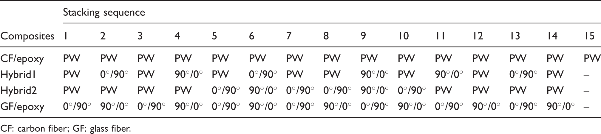
CF: carbon fiber; GF: glass fiber.
For carbon fiber (CF)/epoxy composite, 15 plain weave (PW) sheets were used obtaining a volumetric fraction (φ) = 54%. For glass fiber (GF)/epoxy composites, 14 sheets were used and φ = 55% was obtained. Finally, for hybrids composites, φ = 53% reinforcement, totalizing eight CF sheets and six GF sheets, φ = 54% carbon and φ = 46% glass were obtained. Theoretical reinforcement volume fractions were calculated according to literature. 34
Composites were processed by resin transfer molding (RTM) using a Radius 2100 cc RTM Injector with 2.5 MPa of pressure and 0.05 MPa of vacuum. Previous condition was chosen considering impregnation from previous study. 35 Injection temperature and cure time were chosen from DSC and viscosity results according to methodology presented in the next section.
The characterization of epoxy resin was carried out using DSC, viscosity, TGA and DMA. Composites were studied in relation to void content, TGA, DMA and scanning acoustic microscopy (C-Scan).
Epoxy resin characterization
Dynamic and isothermal DSC were performed using a Perkin Elmer equipment model DSC 8000 to verify cure cycle conditions of the resin analysis, which followed the procedure: heating rate of 10℃.min−1, under N2 atmosphere in a temperature range of 25℃ to 300℃. Later, three different isothermal temperatures based on dynamic run (between onset and peak temperature) were performed.
Resin viscosity was carried out prior using Brookfield viscometer model DV-II + PRO – RV with spindle type SC4-27. For the former, before analysis, epoxy resin was heated up to 50℃ aiming to decrease viscosity for casting in the aluminum crucible of the equipment. Temperatures of analysis were lower than onset temperature measured in dynamic DSC.
TGA of epoxy resin, as well as composites, was carried out using an SII Nanotechnology INC model TG/DTA 6200 under N2 flow in a temperature range from 24℃ to 900℃ in a heating rate of 10℃.min−1.
DMA was performed using an SII Nanotechnology INC model DMA 6100 with specimens of 50 × 10 × 3 mm in a heating rate of 1.5℃ under N2 atmosphere from –186℃ to 210℃ according to ASTM D4065 at five different frequencies: 0.5, 1, 2, 5 and 10 Hz. The specimens were tested using three-point bending clamp. Isothermal test was realized in a temperature range from 30℃ to 200℃, at frequencies: 0.01, 0.02, 0.05, 0.1, 0.2, 1, 2, 5, 10, 20 and 50 Hz in steps of 10℃. The same conditions were used for the composites.
Composites characterization
Aiming to measure specific defects and void content of the processed composites, C-Scan and acid digestion test were performed, respectively. Acoustic inspection C-scan microscopy was carried out for all laminate composites using MI-SCAN equipment, with an insert program MUIS32 from MATEC for data achievement. Data were collected using a concave transductor of 2.25 MHz frequency and analyzed using I-view software, also developed by MATEC with color-associated images.
To characterize void volume fraction, acid digestion was performed according to ASTM 3171 (Proc. B). Matrix was digested with sulfuric acid at 150℃ for 3 h. Fibers resulted from the process were removed using hydrogen peroxide and, finally, washed with distilled water. Considering the density and mass of each material, it was possible to know the resin and fibers volume fraction, as well as void volume fraction, obtained by the difference between the fiber and resin fraction. 36
Results and discussion
Processing results
DSC and viscosity of epoxy resin are presented in Figure 1(a) to (c). Figure 1(a) presents dynamic DSC run for neat epoxy. Initial (132℃), onset (171℃), maximum peak (210℃) and endset (254℃) temperatures were obtained from the curve and so, curing isothermal (Figure 1(b)) at 150℃, 180℃ and 210℃ were verified aiming at checking the optimum cure time. The respective curing times for the three isothermal temperatures were 350 min, 150 min and 50 min (Figure 1(b)). The temperature of 180℃ was chosen due to the balance between processing time and void minimization, which is dependent on the heating flow, viscosity, pressure, vacuum, permeability among other factors.34,35 Figure 1(c) shows the viscosity of epoxy resin at three different isothermal temperatures, aiming to obtain optimum processing temperature. The increasing of temperature makes the viscosity value decrease (whereas molar mass is constant). Next step is followed by an increase of viscosity due to starts of curing reaction proceeds.
37
Due to lower viscosity value, the temperature of 120℃ was used in order to allow a combination of lower void content,
35
which leads to a flow uniformity and less void formation, ensuring appropriate impregnation time without fiber misalignment.35–39
(a) Dynamic, (b) isothermal DSC and (c) viscosity analyses for the neat epoxy resin. DSC: differential exploratory calorimetry.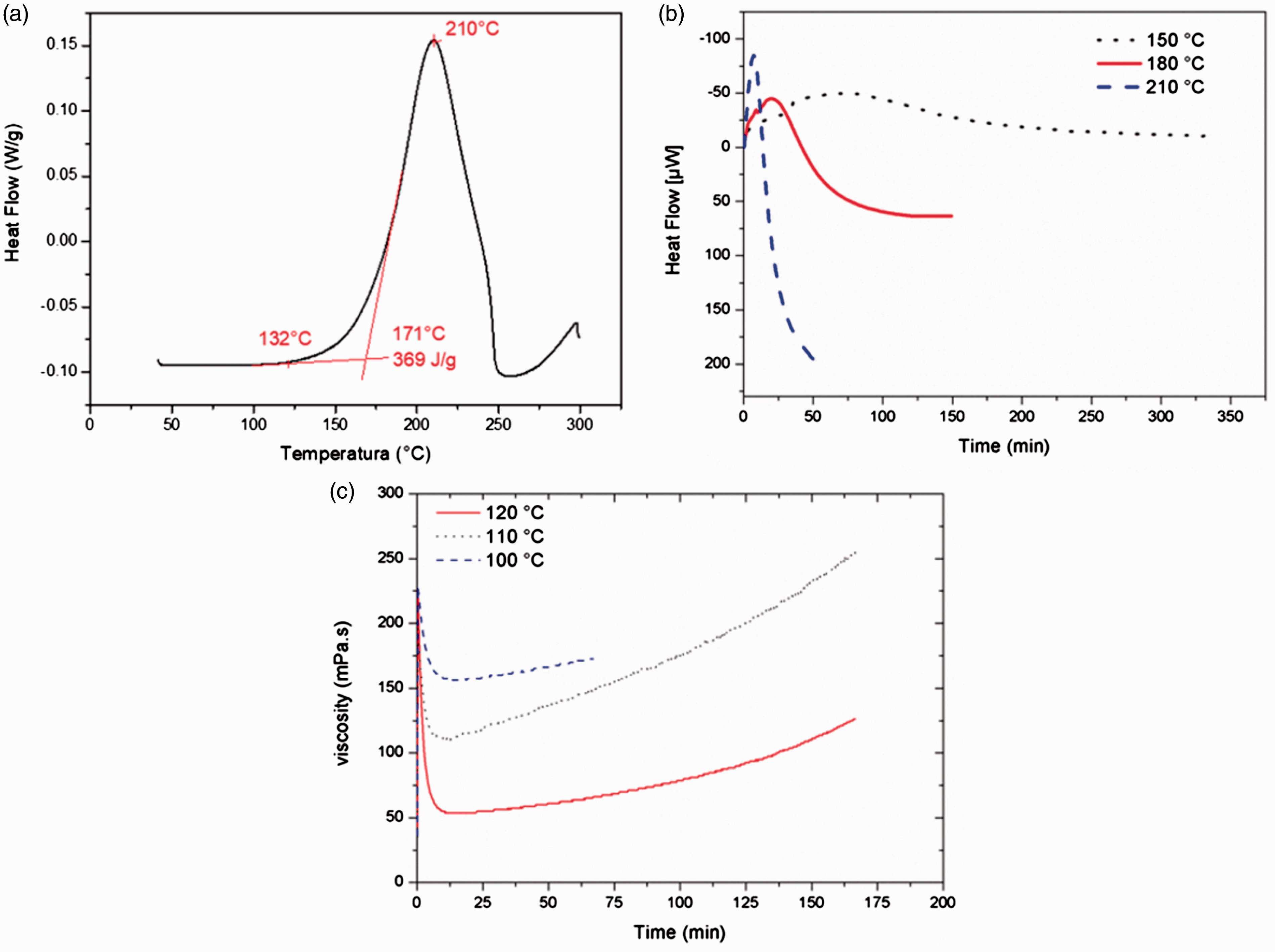
Figure 2(a) to (e) presents attenuation map (C-scan) for composites processed. Colors scale (Figure 2(a) represents attenuated signal issue, i.e. white color means 100% return of the issue signal and the black color presented 0% of emitted signal returned. In general, composites present heterogeneities with respect to resin impregnation. For CF/epoxy composite (Figure 2(a)), near the inlet, an attenuation of ≈ 40% (black circle) associated to voids is observed. Carbon plain weave reinforcement presents a lower diameter, which contributes to fiber packaging and difficult flow path and generating more voids.
40
In addition, the impregnation difficulty is responsible for defects in the laminates, mainly near laminate end of the composite (red circles). These defects presented attenuation between 80% and 100%, associated to macroscopic voids and other defects, e.g. fiber misalignment, lack of fiber filaments or bubbles trapped in the system. For both hybrids and GF/epoxy composites, similar values in relation to impregnation heterogeneity with attenuation of the signal between 20% and 40% can be observed. Hybrid 2 presented the greatest homogeneity in impregnation, which is related to glass fiber in the middle of the configuration which facilitates the resin flow along the composite, as shown by Monticeli et al.
35
C-scan maps of composites using ultrasonic inspection: (a) scale, (b) CF/epoxy, (c) hybrid 1, (d) hybrid 2 and (e) GF/epoxy. CF: carbon fiber; GF: glass fiber.
Void content for the composites studied. a
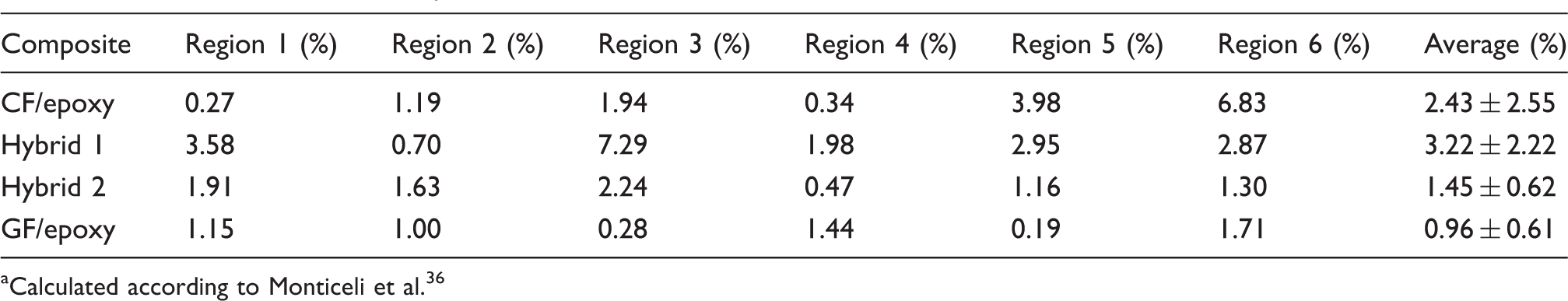
Calculated according to Monticeli et al. 36
CF/epoxy composite presents a tendency to increase voids from inlet to laminate end regions. In regions 5 and 6, void content is considered higher for structural application, which requires values less than 2%. CF/epoxy results in 2.43% of average void volume fraction with higher standard deviation (2.55). This confirms previous analysis, where carbon fiber presents lower diameter and difficult impregnation, resulting in high void formation. The same behavior was observed for Hybrid 1, which presented highest porosity in region 3 (highlighted in C-scan map with red circle (Figure 2(c)). Hybrid 2 porosity values were similar along the laminate, showing homogeneity in resin impregnation from C-scan maps and ensuring better impregnation. This fact indicates that glass fabrics, when concentrated in the middle of the hybrid laminate maintains the best impregnation amongst all laminates with low void formation.
According to Monticeli et al., 35 impregnation in Hybrid 2 decreased void content, since glass fiber in the middle of the carbon preform creates a second flow in vertical direction, as theoretically and experimentally demonstrated. Interleaved stacking sequence (Hybrid 1) presented high tendency of void content, since it increases the number of hybrid interface and neglects the second flow, making impregnation difficult.
Thermal analysis
Figure 3(a) and (b) present TGA and the respective derivative (DTG) curves for epoxy resin and the laminate composites, respectively. The main degradation stages presented for epoxy resin and composites were obtained from TGA curves.
TGA for epoxy resin and the laminate composites: (a) weight (%) and (b) DTG. TGA: thermogravimetric analysis.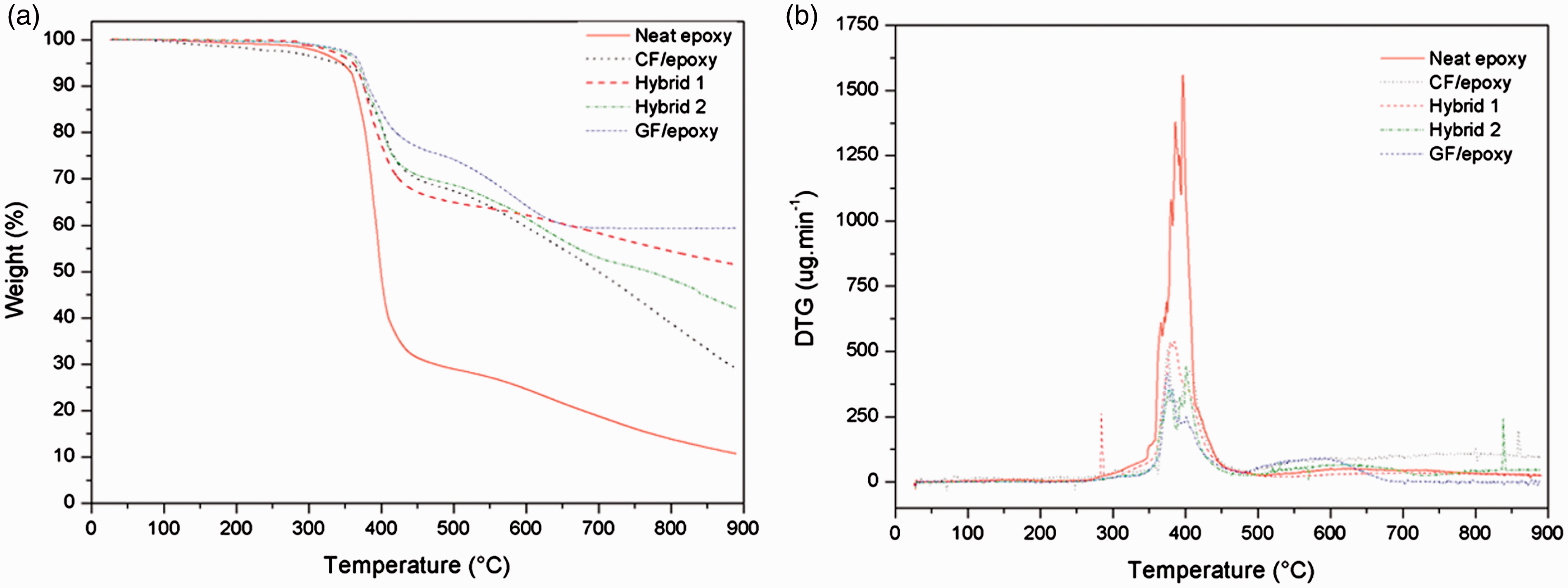
Stages of degradation and weight loss for all materials studied.
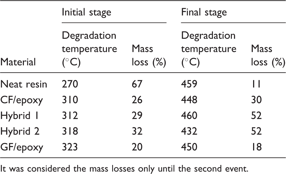
It was considered the mass losses only until the second event.
When a polymeric material is subjected to a constant stress, their viscoelastic properties will decrease over a period of time, due to molecular rearrangement in an attempt to minimize the localized stresses. So, the moduli measured over a short time (high frequency) resulted in higher values.
42
At higher frequencies (short times) there is a decrease in rotational and translational motions of molecular chains, which require more energy to start cooperative movement
19
and vice-versa. So, it is important to measure this property at different frequencies regarding service life utilization. Storage modulus, loss modulus and tan delta from dynamic mechanical analysis for epoxy resin at different frequencies is presented in Figure 4(a) to (d). Two distinct relaxation peaks for all parameters analyzed can be observed: the first related to beta relaxation (T
β
), at ≈ –100℃ and the second related to the main transition (T
g
), at ≈ 100℃ (the values are referred to the storage modulus).
43
Higher the frequency used, lower the time for response of the material, which causes changes in relaxation time of the materials shifting the events to higher temperatures.19,43
DMA for epoxy resin at different frequencies: (a) storage modulus, (b) loss modulus, (c) tan delta and (d) T
β
detail. DMA: dynamic mechanical analysis.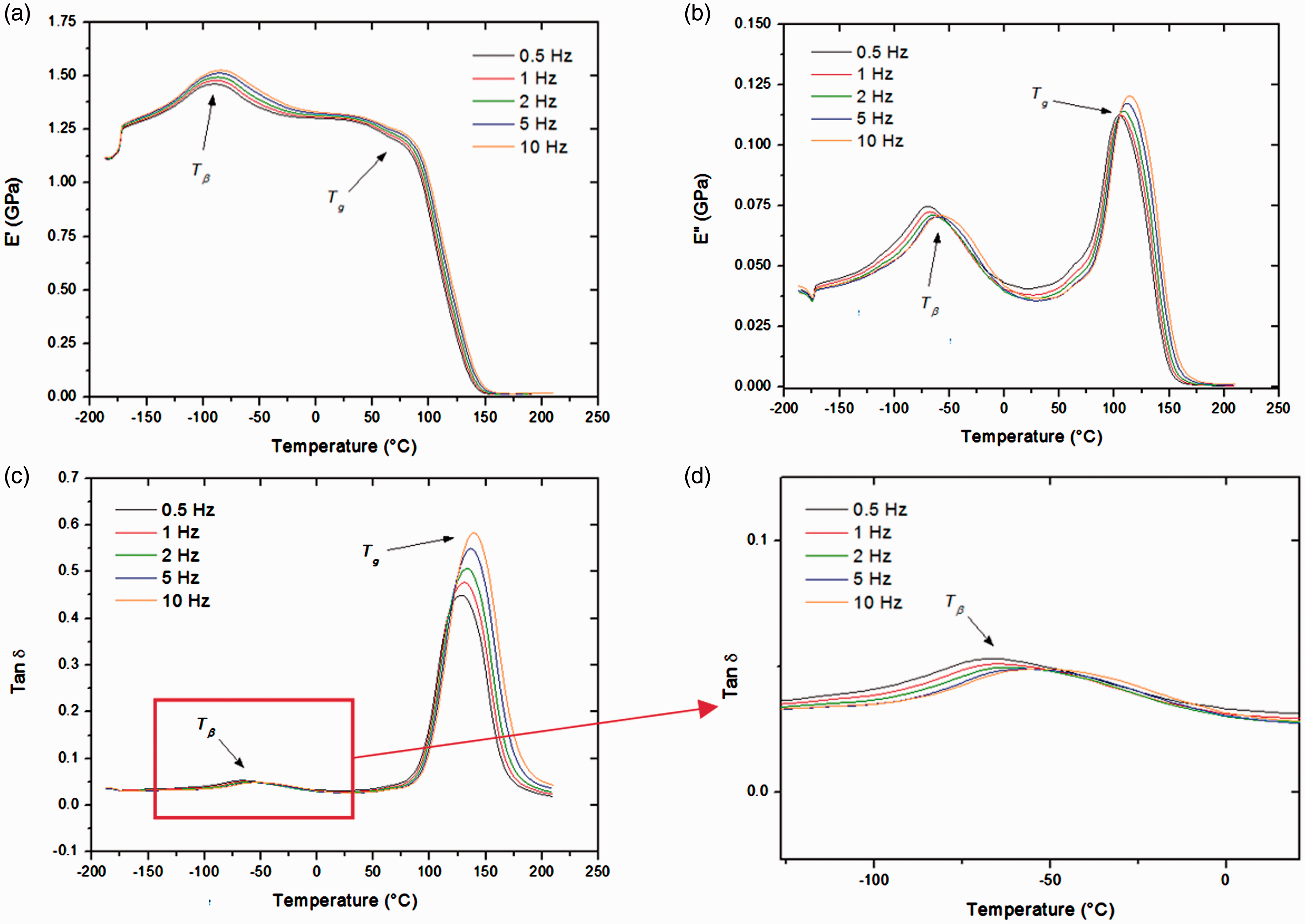
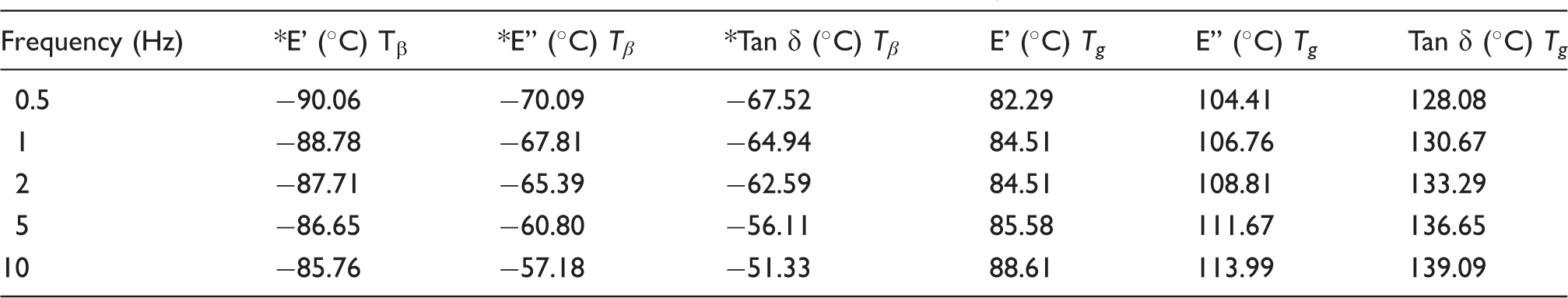
Storage modulus, loss modulus and tan delta for epoxy resin at T β and Tg at all different frequencies.
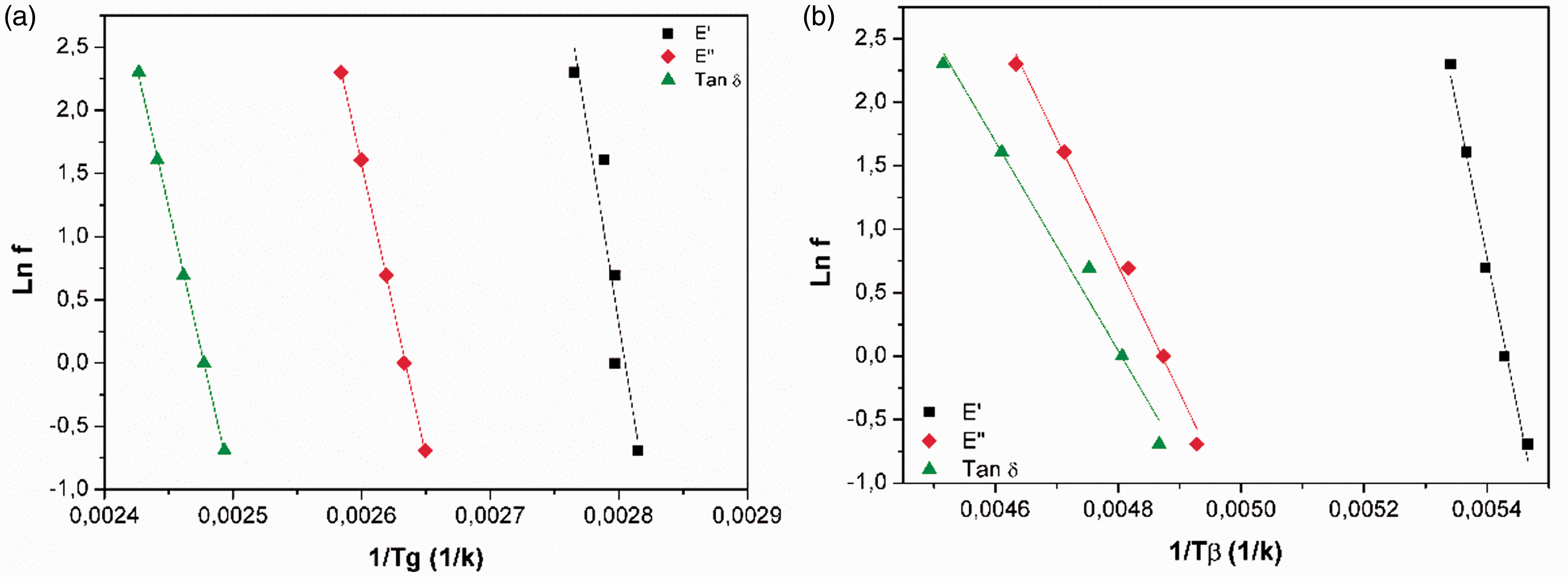
From different frequencies, it is possible to estimate the activation energy (E
a
) values from both transitions.
45
E
a
is obtained from slope of the straight line fitted from the transitions by ln(f) versus(1· Activation energy for epoxy resin: (a) T
β
and (b) T
g
.
DMA analysis for Hybrid 1 is represented in Figure 6. All composites behave similarly in relation to the frequency variation but with different values, i.e. all transitions shift to higher temperatures and loss and tan delta increase the respective dissipation peaks. As earlier mentioned, this is due to differences in molecular response at different times.
DMA result for hybrid 1 composite at different frequencies: (a) storage and tan delta and (b) loss modulus. DMA: dynamic mechanical analysis.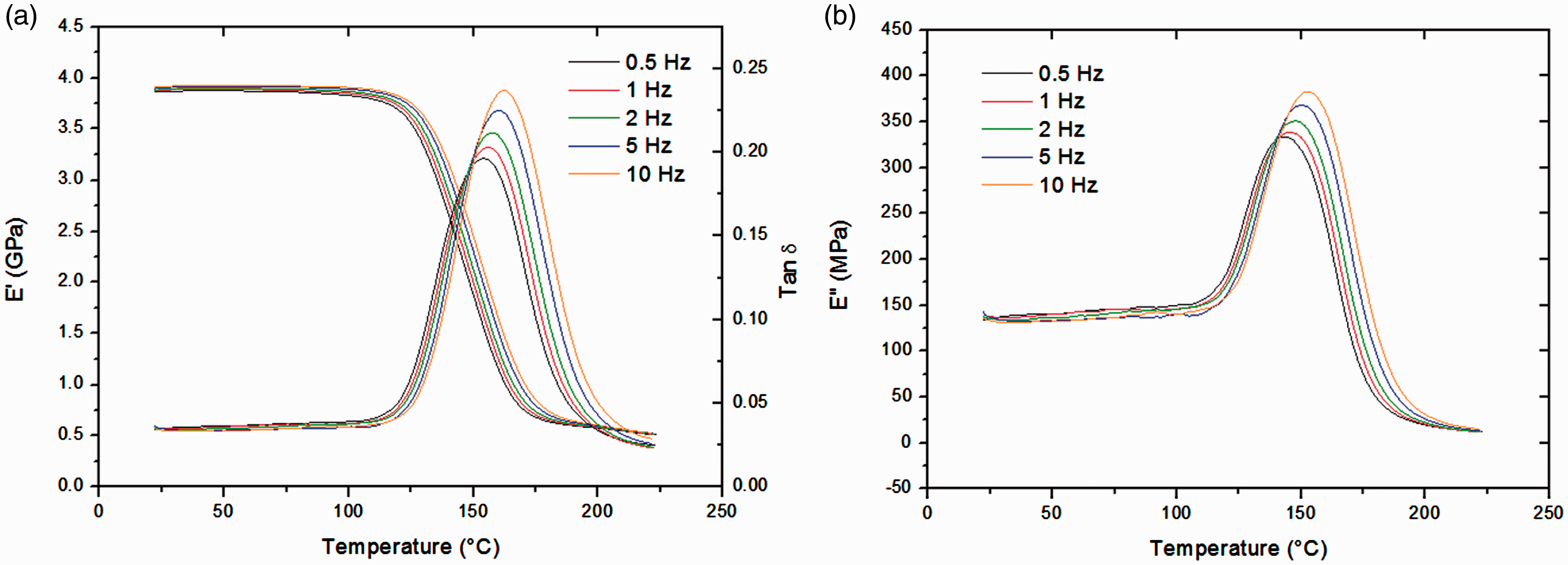
Glass transition variations for all laminate composites calculated from storage modulus, loss modulus and tan delta curves at different frequencies.
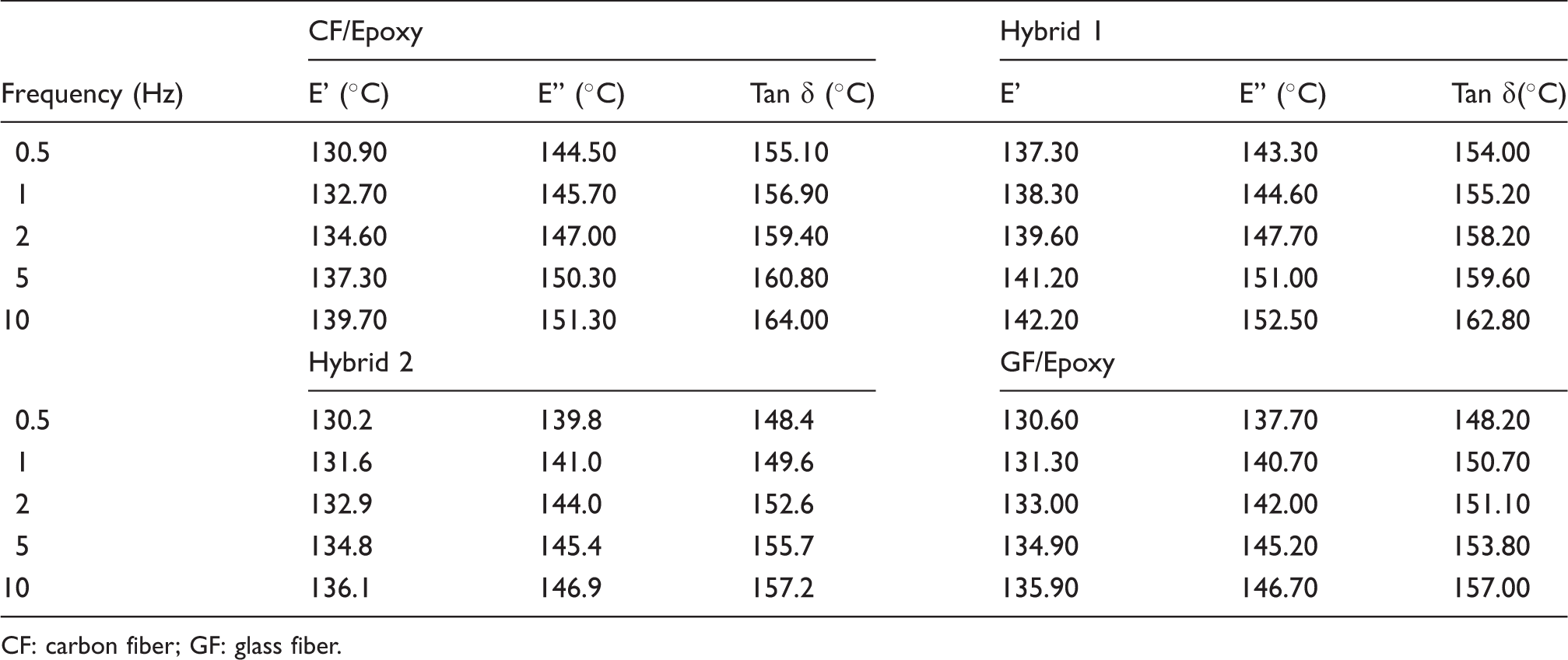
CF: carbon fiber; GF: glass fiber.
Activation energy values calculated in the storage modulus, loss modulus and tan delta.
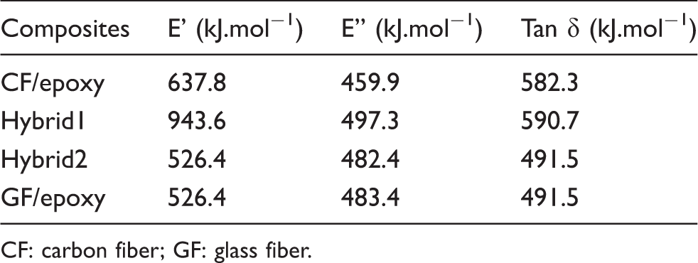
CF: carbon fiber; GF: glass fiber.
A similar behavior can be noted in the processing conditions (C-Scan + porosity) and in the thermal behavior between GF/epoxy composite and Hybrid 2, which concentrates the amount of glass fiber in the middle of composite. Molecular restriction at different parameters is corroborated by lower void content and impregnation homogeneity observed in C-Scan attenuation maps. Hence, differences between carbon fibers impregnation are minimized and physical impregnation characteristics are improved as well in composite interface.
35
According to Baxter et al.,
48
porosity could act as thermal insulation during thermal exposure through the composite. As a result, activation energy is highly dependent of porosity, as observed in Figure 7 (E
a
calculated from onset of storage modulus).
Porosity versus activation energy (calculated from E′).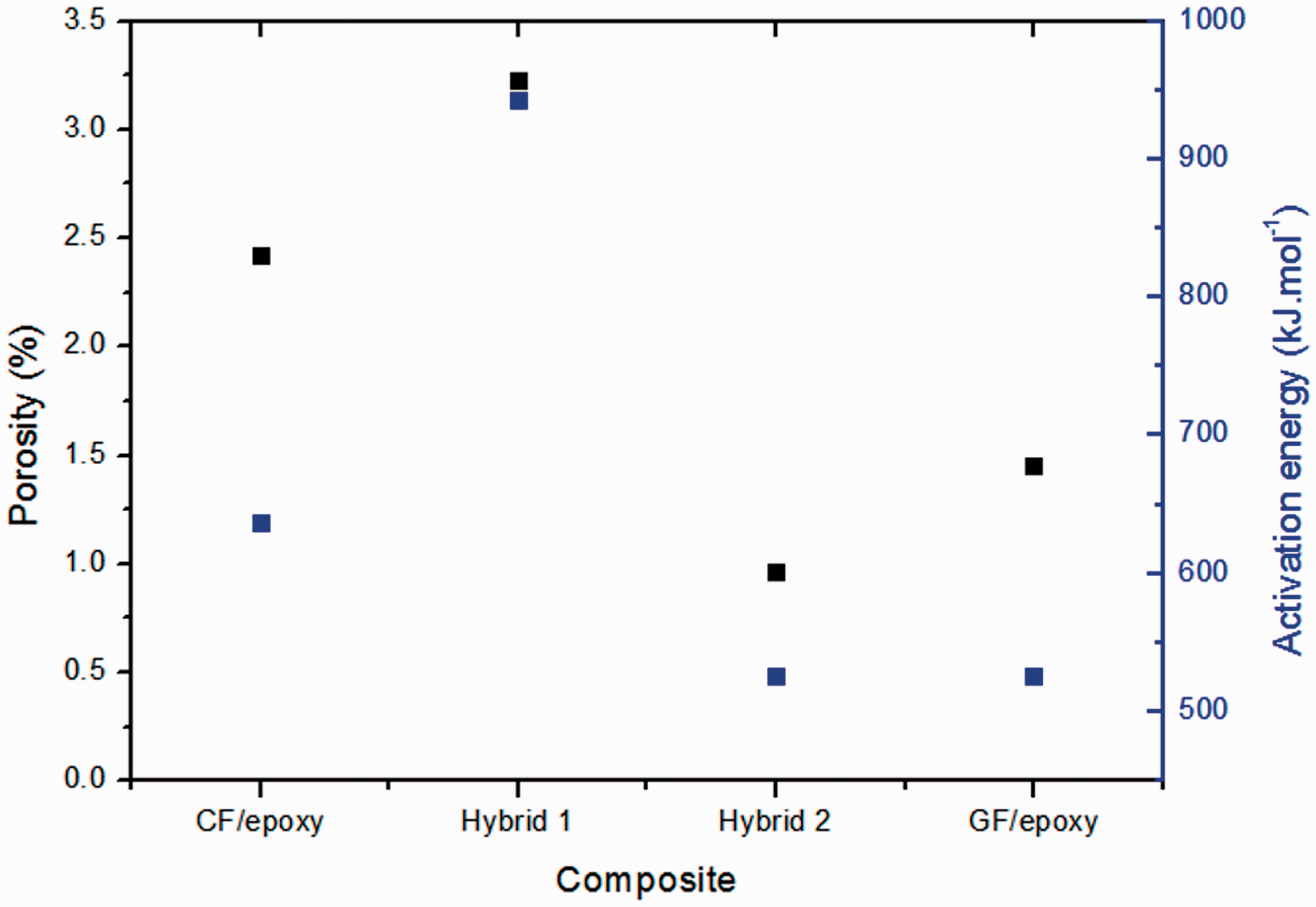
According to Wang et al., 49 porosity blocks heat transfer through material, preventing the composite from achieving higher thermal conductivity. In addition, Zhu et al. 50 mention that void acts as a new phase in the material creating a “barrier” that decreases thermal conductivity. Considering that Hybrid 1 presents higher void content, activation energy needs to be higher to overcome the resistance created by void content.
Figure 8(a) to (d) shows the storage, loss, tan delta and Cole-Cole plots for all composites at 1 Hz frequency for comparison. Cole-Cole was plotted aiming at corroborating with molecular heterogeneity which is related to the width of the relaxation curve (loss or tan delta). According to Figure 8(a), CF/epoxy composite showed higher storage modulus when compared to other composites. Hybrid composites showed a positive effect when compared to GF/epoxy. A decrease of storage modulus from Hybrid 2 to 1 is related to differences in fabric architecture of both composites as also observed for Murugan et al.
51
In spite of higher void content presented for CF/epoxy composite, lower dissipation energy is observed by tan delta curve and a higher storage modulus in the glassy region. This lower dissipation is usually associated with interface quality for composite materials. Hybridization plays a positive effect on this property, leading out to higher storage modulus and lower dissipation energy when compared to the glass fiber composite.
Comparison of: (a) storage modulus, (b) loss modulus, (c) tan δ and (d) Cole-Cole.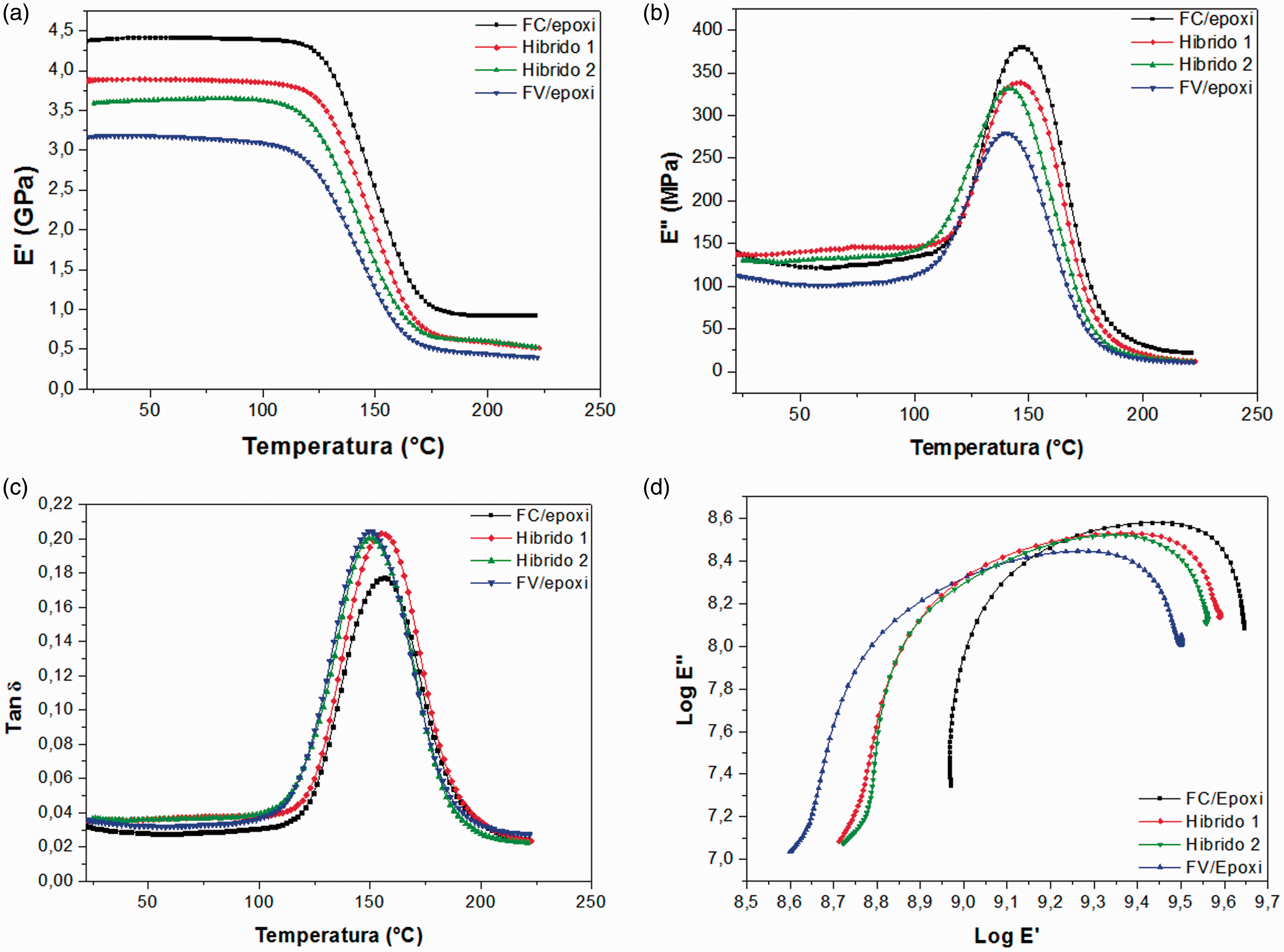
Cole-Cole plot is indicative of the structural molecular homogeneity of the composite.43,52 The homogeneity can be measured by the diameter of the semicircle. 52 Cole-Cole presents a direct response of impregnation behavior. According to values measured for the semicircle (8.72–9.59 = 0.87 and 8.74–9.56 = 0.82), Hybrid 1 is more heterogeneous when compared to Hybrid 2 composite. So, configuration of composites also altered molecular homogeneity. This phenomenon is important for fracture behavior definition, because heterogeneity can change fracture behavior, as crack propagation 53 and fragility of the material. This behavior is also observed in C-Scan results, in which Hybrid 2 presented more impregnation homogeneity, resulting in lower porosity content and, consequently, higher molecular homogeneity when compared with Hybrid 1.
Long-term measurement
The measurement of the long-term properties30,54,55 based on accelerated tests is important for saving time and costs since it can predict mechanical properties which would take years. Based on the understanding of material behavior regarding frequency, it is possible to estimate the long-term properties by knowing the abscissa axis is frequency or time according to equation (1)

By applying the logarithmic function on equation (1), equation (2) is obtained

All samples were measured in two different isothermal temperatures: 30℃ and 130℃. The former temperature was chosen because it is the range temperature of aeronautical service composites (between 15℃ and 40℃) . The second temperature is the glass transition temperature of the resin from the tan delta curve. The frequency range of the main relaxation depends on each isothermal temperature. Figure 9(a) and (b) shows the isothermal curves obtained from 30℃ and 130℃ as reference temperature, respectively. For the former the transition occurs at lower frequencies, i.e. higher temperatures according to the time-temperature superposition. Using 130℃ as reference temperature, due to higher molecular mobility achieved from thermal excitation and so more free volume is available in the sample, the translational movement of chain segments is easy and so the events are shifted to higher frequencies, i.e. lower temperatures. Consequently, a more significant change in modulus in frequency function is observed.
30
Curves in glass transition range as frequency function for neat epoxy at (a) 30 ℃ and (b) 130 ℃. Time temperature superposition (TTs) at two reference temperatures: (c) neat epoxy, (d) CF/epoxy, (e) Hybrid 1, (f) Hybrid 2 and (g) FG/epoxy.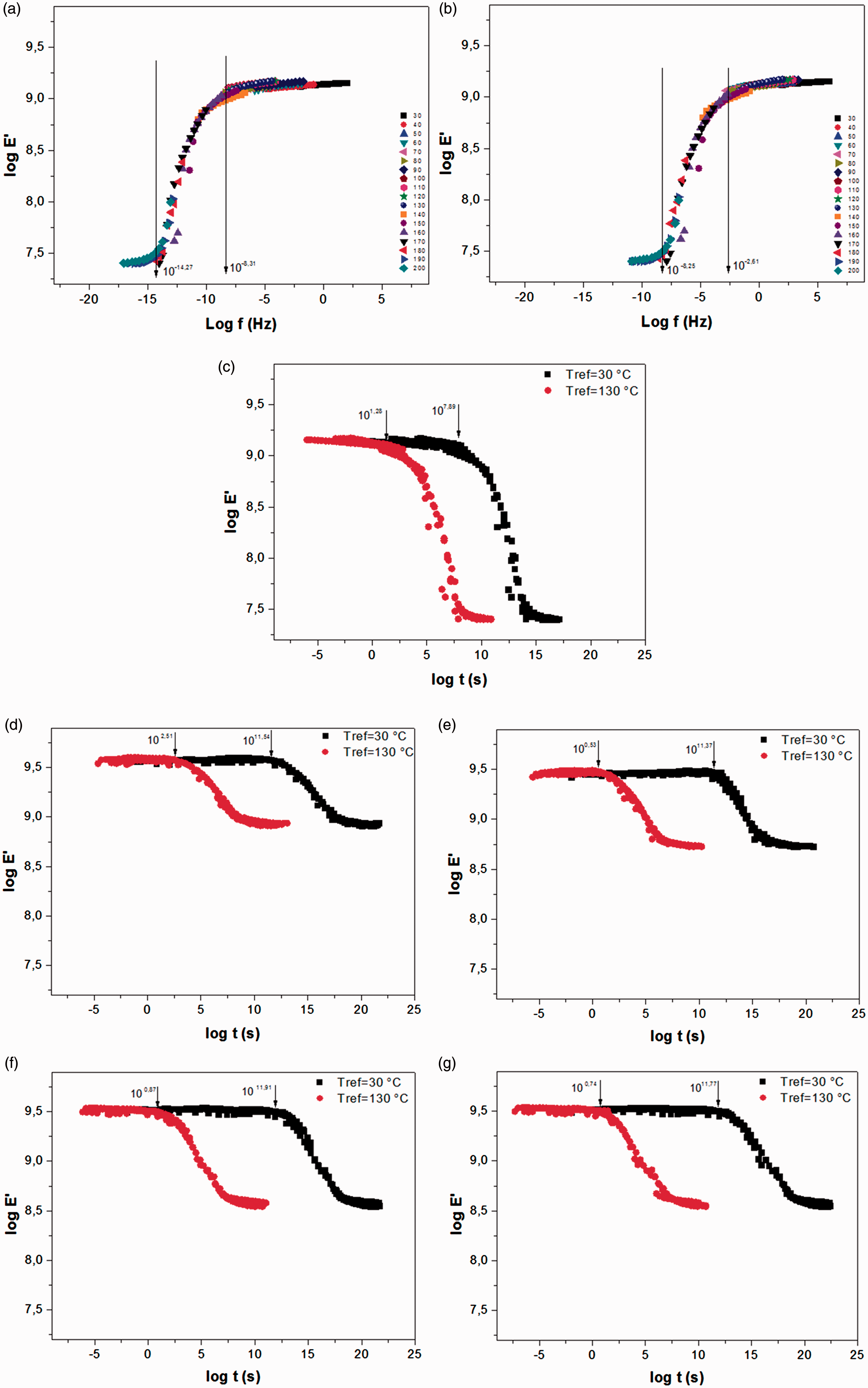
By using Figure 9(a) and (b) and using the shifting factor according to Ferry, 30 the storage moduli in time function was estimated for all samples studied. The storage moduli in frequency function are presented in Figure 9(c) to (g). For the neat resin, using the Tref = 30℃, the onset was around 2.5 years and at Tref = 130℃ was around 19 s, showing a clear influence of temperature on relaxation of the chain segments of the polymeric material. For CF/epoxy (Figure 9(b)), at Tref = 30℃ the relaxation time was of 11,000 years and for Tref = 130℃ was around 5 min. For Hybrid 1 and Hybrid 2, the relaxation times at Tref = 30℃ were 7400 years and 25,000 years, respectively, and for Tref = 130℃ were 3.38 s and 7 s. For GF/epoxy at Tref = 30℃ the relaxation time was 18,000 years and for Tref = 130℃ was 5.49 s.
Conclusions
Four types of composite laminates, i.e. CF/epoxy, Hybrid 1, Hybrid 2 and GF/epoxy composites, were investigated under dynamic mechanical and thermal analyses. To effectively improve the properties of the glass fiber composite, glass/carbon fiber reinforcement was used either by introducing the carbon layers at the external or by introducing different stacking sequence of fiber fabrics. In some cases, hybrid composites replace carbon fiber composites properly, when it is aimed at reducing costs in the production for aeronautical components. By means of the DMA, it was possible to understand the effect of different reinforcement types in the viscoelastic phenomena of composites and their matrix, and the long-term properties were predicted successfully. The incorporation of glass fiber in the middle of composite leads to similar thermal behavior and improve dynamic mechanical analysis when compared to the GF/epoxy composite. So, by changing the reinforcement architecture, a reduction of the cost (by including lower carbon fiber uses) and an improvement of the properties were obtained, mainly for the Hybrid 2 composite.
Footnotes
Declaration of Conflicting Interests
The author(s) declared no potential conflicts of interest with respect to the research, authorship, and/or publication of this article.
Funding
The author(s) disclosed receipt of the following financial support for the research, authorship, and/or publication of this article: The Fundação de Amparo à Pesquisa do Estado de São Paulo - FAPESP (process numbers: 2015/19967-4, 2015/10906-2 and 2016/07245-7), Coordenação de Aperfeiçoamento de Pessoal de Nível Superior - Brasil (CAPES) - Finance Code 001 and CNPq (process number: 153335/2018-1). Finally, the Brazilian National Council for Scientific and Technological Development CNPq (process number: 153335/2018-1).