
Abstract
The aim of this study was to improve four-point bending performance of foam core sandwich composite beams by applying various core machining configurations. Sandwich composites have been manufactured using perforated and grooved foam cores by vacuum-assisted resin transfer moulding method with vinyl-ester resin system. The influence of grooves and perforations on the mechanical performance of marine sandwich composite beams was investigated under four-point bending test considering the weight gain. Bending strength and effective bending stiffness increased up to 34% and 61%, respectively, in comparison to a control beam without core modification. Analytical equations were utilised for calculating the mid-span deflection, equivalent bending stiffness and ultimate bending strength of the sandwich beams. Finite element analysis was also performed to analyse the flexural response of the specimens taking into account the combined effect of orthotropic linear elasticity of the face sheet and the non-linear behaviour of the foam core.
Introduction
Composite sandwich beams are commonly used in engineering structures owing to their satisfactory specific bending strength and stiffness properties.1–3 Additional advantages such as ease of fabrication, buoyancy and resistance to harsh marine environment make composite sandwich members ideal choice for marine industry.4–7 Typical marine applications have been demonstrated using glass, carbon or Kevlar fibre-reinforced laminated polymeric composite face sheets with balsa wood, closed-cell poly-vinyl chlorides (PVC) and polyester non-woven mat fabrics as core materials.8–11
In modern boat and yacht manufacturing, vacuum-assisted resin transfer moulding (VARTM) method is commonly used to manufacture large hull and deck components. The VARTM method enables defect-free marine sandwich composites with a great dimensional stability and a high fibre volume content.12,13 Perforated, grooved and/or web foam core patterns are preferred in the industry in order to enhance the resin flow across the face–core interface and face fabrics of the marine sandwich panels. In addition, the grooves, perforations and webs act as a link between the face sheet and the foam core which increases the contact strength between the surfaces and improves the structural integrity of the sandwich construction.
Such core modifications however increase the weight of the sandwich panels due to the increased resin volume.14–17 Therefore, the influence of core modifications on the mechanical properties of sandwich structures has been investigated by a number of researchers.18–33 Mitra 18 revealed the efficiency of introducing the semi-circular shaped grooves into the sandwich panels to improve the shear performance. It was shown that the delamination initiation load of sandwich composite columns subjected to in-plane compressive loading could be increased approximately 25% by inserting pre-manufactured shear keys in foam-core grooves. 19 Several numerical studies have also been conducted on the effect of the shear key diameter, orientation and pitch on the in-plane shear behaviour of the foam core sandwich panels.20–23 Finite element analysis (FEA) considering the non-linear response of the foam core showed an improvement in the initial stiffness and ultimate stress of the sandwich panel as a result of the shear keys. Juliyana and Krishnan 24 reported that the split semi-torus keys improve the resistance against debonding failure. The shear load carrying capacity of the split semi-torus panel was improved by 22% in comparison to a plain foam core panel. Halimi et al. 25 studied perforated foam core sandwich (PRFS) panels with different hole patterns. They found that both hexagonal and square arrays increased the three-point bending performance. Fang et al. 26 observed that the grooved-perforated foam core improve flexural bearing capacity of the sandwich beams under four-point bending (4PB) load. According to May-Pat et al., 29 circular perforations increased the flatwise compression strength with a slight improvement of fracture toughness. However, the specimen weight was increased by 30%. Abdi et al.27,28 indicated that the flexural and flatwise compression strength are increased as the diameter of cured-resin pins increased.
In case of web-foam core structures (WFSs), a number of experimental and analytical studies have been performed.34–40 Wang et al. 35 reported that ultimate bending strength and initial bending stiffness of the web-foam core sandwich (WFS) panels could be enhanced by increasing the web thickness and web height under 4PB. Qi et al. 36 studied on a two-way bending behaviour of WFS panel under conditions of four simply supported edges. The webs significantly improved the limit bearing capacity and the rigidity of sandwich panels, where smaller web spacing resulted in a stronger effect. Wu et al. 37 conducted a quasi-static compression experiment on a WFS panel. Compared to conventional composite panels, a substantial increase in the peak strength was achieved by using a web core. Work by Fathi et al. 38 indicated that the webs filled with resin showed a reinforcing effect on PVC foam against transverse shear stresses leading to higher shear strength and stiffness.
Despite the individual efforts devoted for understanding the mechanical behaviour of grooved and perforated foam cores, there is a lack of information in the open literature regarding comparative studies on the influence of core modifications. The present article complements the existing literature by investigating and comparing the effect of modified core configurations on the bending properties of marine composite sandwich beams. Four-point bending test was used to collect data on failure modes, bending strength and bending stiffness. Simple analytical predictions in elastic region were presented and compared with the experimental results. FEA simulations were also conducted to further validate the flexural response of the sandwich beams using the effective mechanical properties of the constituent materials.
The findings of this research will provide valuable insights for boat designers/manufacturers on effective core machining process. Furthermore, desired modifications can be simply applied by core material suppliers without the need of additional machining operations.
Experimental and numerical study
Materials and manufacturing methods
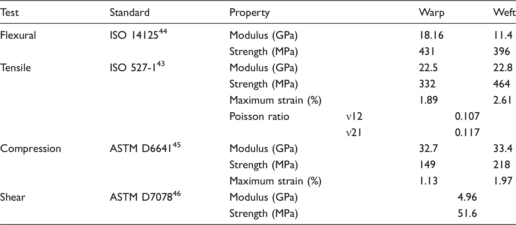
The effective mechanical properties of [0/90]2s E-glass/vinyl-ester face sheet.
This article concentrates on five different design configurations: PRFS, WFS, perforated-web-foam core sandwich (PRWFS), grooved-foam core sandwich (GFS) and perforated-grooved-foam core sandwich (PRGFS) structures. Specimens with a plain foam core were also used as standard control specimens. Schematics of the core modifications are given in Figure 1. The core materials were machined by a computer numerical control mill, including 2 and 4 mm diameter holes. The resin cured in these holes and grooves formed the solid pins and ribs. In the previous studies, dry areas were observed in the specimens when the distances between the centre of holes increased above 30 mm.
25
Therefore, the distance between the centres of the holes in this study was set to 30 mm.
Schematic representation of the core modifications (dimension in mm): (a) perforated-foam core in square arrangement (PRFS_Ø2,4S), (b) perforated-foam core in regular arrangement (PRFS_Ø2,4R), (c) web-foam core (WFS), (d) perforated-web-foam core (PRWFS), (e) grooved-foam core (GFS) and (f) perforated-grooved-foam core (PRGFS).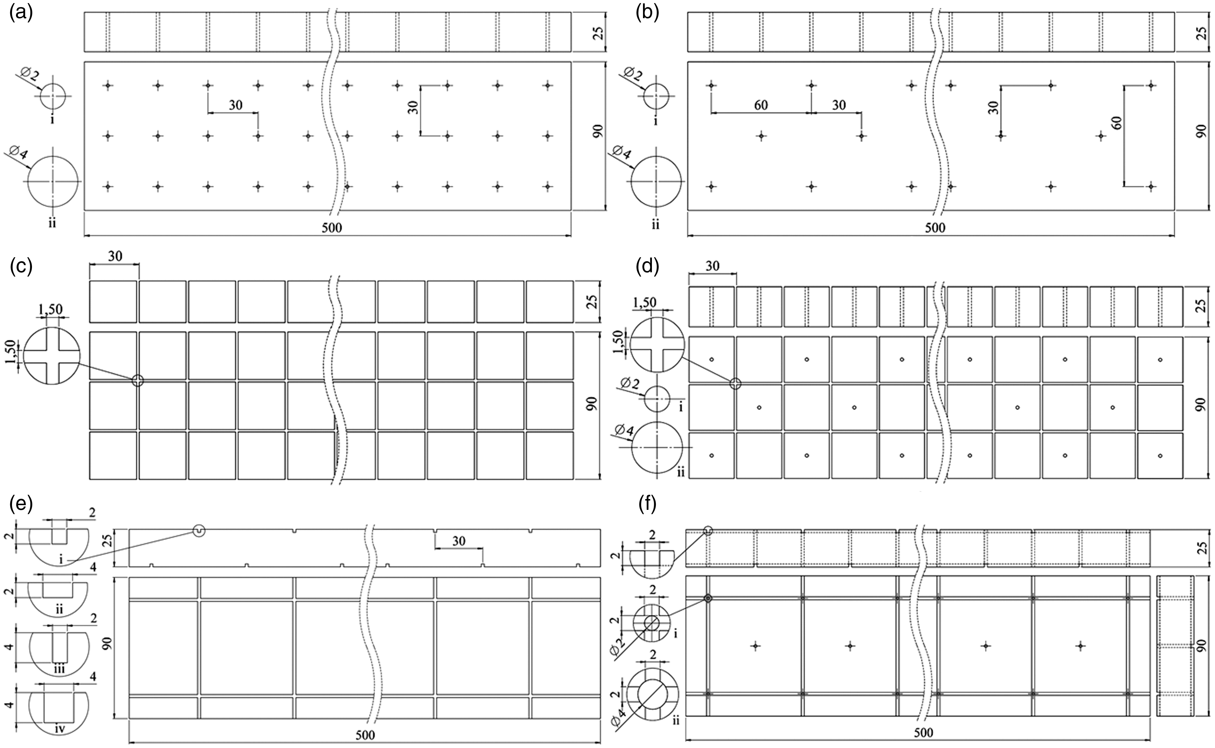
Figure 1(a) and (b) shows the PRFS designs, with 2 and 4 mm diameter holes through-the-thickness of the PVC foam in square ‘S’ and regular ‘R’ array patterns. Figure 1(c) shows WFS comprising crosswise through-thickness grooves with 30 mm space in between with scrim cloth on one side. The perforated web-foam sandwich structure was referred to as PRWFS specimen as shown in Figure 1(d). GFS specimens include 2 mm × 2 mm, 4 mm × 4 mm, 4 mm × 2 mm and 2 mm × 4 mm grooves that were offset 30 mm from each other on the top and bottom surfaces of the foam, same as the hole distance to avoid resin wetting problem (see in Figure 1(e)). Perforated-grooved foam core specimens with 2 mm × 2 mm grooves and a hole diameter of 2 and 4 mm (referred to PRGFS) are illustrated in Figure 1(f). It was observed that surface grooves on the PVC foam increased the shear properties and delamination resistance of ordinary sandwich panels.18,19 Therefore, the groove geometry was kept small so that the weight penalty was minimal.
Four-point bending test
Four-point bending test of the specimens was conducted in accordance with the ASTM C393/C393M-16 standard.
47
The 4PB test coupons of 500 mm × 90 mm × 30 mm were cut from the larger sandwich panels. The length of the support span was 450 mm. The loading pin and the supports had a diameter of 50 mm to prevent local indentation failure on the beam as recommended in the standard. A Zwick Roell Z-250 testing machine with a 250 kN load cell was used to load the specimens at a constant crosshead speed of 6 mm/min. Figure 2 shows the test set-up. Five specimens for each sandwich beam configuration were tested in warp direction. In order to determine the initial bending stiffness of the beams in the elastic region, mid-point deflections were measured with a dial strain indicator. Two longitudinal strain gauges were attached to the top and the bottom face sheets at the mid-span to detect the relation of the load and the face sheet strain. All specimens were tested up to failure to determine the bending strength and failure mechanisms.
The flexural test set-up.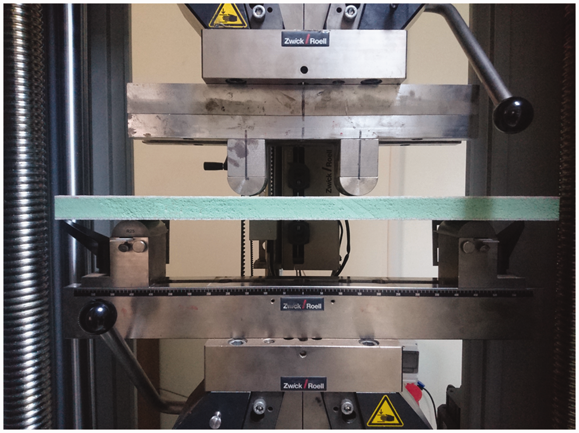
Finite element analysis
FEA of the 4PB tests has been carried out using ANSYS 14.5 finite element software.
48
Owing to symmetrical boundary conditions, only one quarter of the sandwich beam was modelled, as shown in Figure 3, in order to reduce the computational cost. The quarter models were meshed with 20-noded hexahedron solid elements (Hex-20). This structural solid element is defined by 20 nodes having three degrees of freedom per node: translations in the nodal x, y and z directions.
A quarter model of sandwich beam for FEA.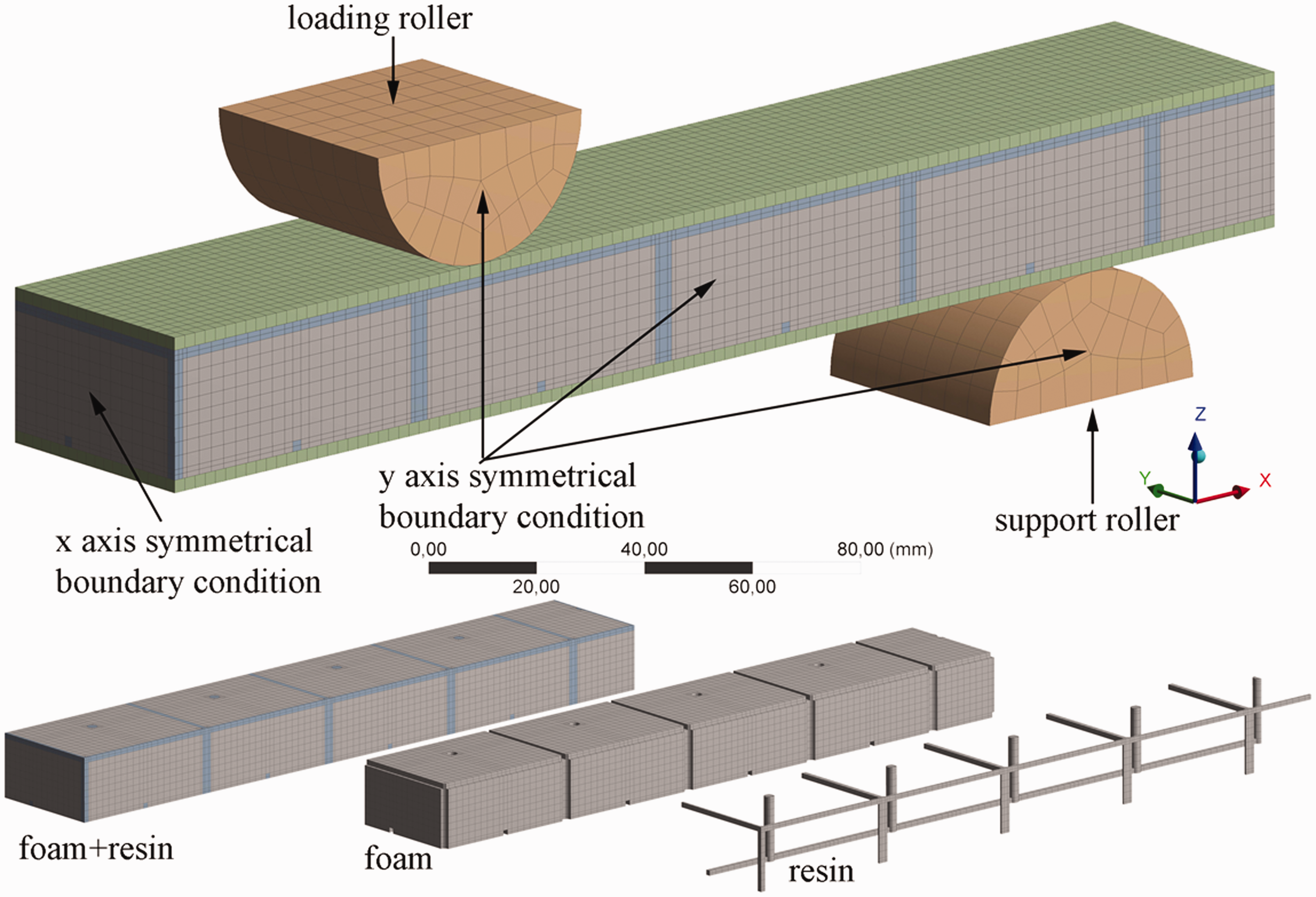
The contact interface between the face sheets and the core was modelled with surface to surface contact algorithm. The face sheets and foam core were assumed to be in full contact and perfectly bonded together.49–52 The face sheet and core faces were treated as the target and contact surfaces, respectively. No-separation (slide free) contact was implemented between the loading pin/top face sheet, and the support/bottom face sheet. For the steel loading pin, all degrees of freedom (except for the displacement along Z direction for load application) were constrained, while the support was fully constrained. Applied displacement was increased up to the point at which the experimental maximum failure load of the specimens was reached. Damage modelling was not considered in this study since the experimental observations confirmed that the complex failure mechanisms such as debonding between the core and the face sheets were negligible until the maximum failure load.
Properties of the PVC foam and cured resin matrix were obtained from data sheets.41,42 The mechanical properties of the face sheet material were measured using standard test coupons and details are given in Table 1. The face sheet laminates were modelled with a linear elastic orthotropic material model since they remain intact until the failure load of the specimens.21,49,51 However, the foam core exhibits an elastoplastic behaviour and it was represented by a multi-linear isotropic hardening material model.32,33,53,54 Post-yield plastic stress–strain data of the foam core was obtained from uniaxial compression tests. For validation purposes, compression and bending tests were conducted in accordance with the ASTM standards.47,55 Figure 4(a) and (b) shows that the FEA and the experimental results are in a reasonable agreement in elastic and post yield regions. The likely reason for the deviation in the curves is the ideal foam behaviour assumption of the FEA where the effects of both material and geometrical imperfections were ignored.
Experimental and numerical load–displacement curves of the PVC foam core under: (a) bending and (b) compression.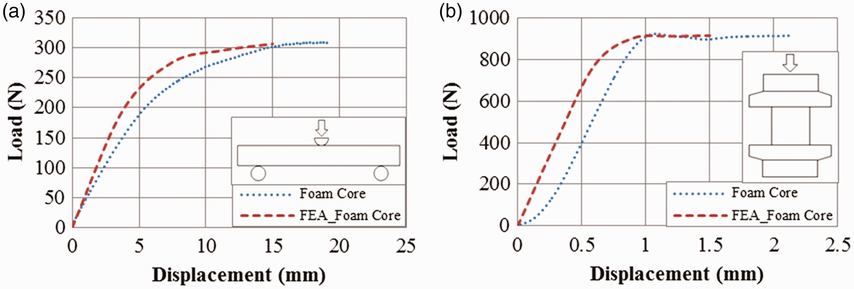
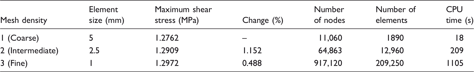
A convergence analysis was carried out based on the maximum shear stress on the foam core using three different element sizes in order to determine the appropriate mesh density (see Table 2). The numerical analyses were performed using an Asus CG8265 PC with an Intel Core-i7-3770 3.5 GHz processor, 8 GB of RAM and a 64-bit Windows 7 Home Premium operating system. Predicted maximum shear stresses for each mesh configuration are presented in Figure 5. Based on these data, intermediate mesh size was selected for all the FEA models.
Maximum numerical shear stresses in foam core as a function of mesh size. Parameters of the convergence analysis.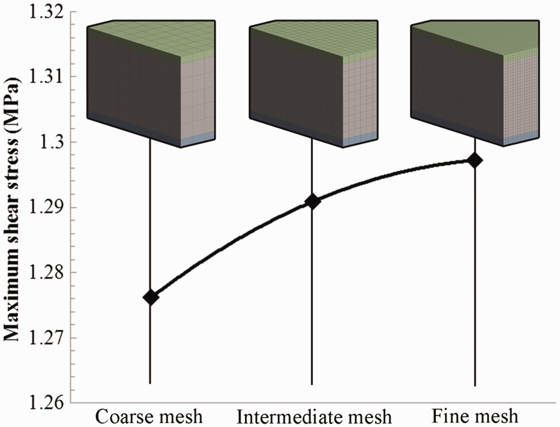
Results and discussion
The load–displacement curves, load–strain response and failure mode of the composite sandwich beams under 4PB tests are reported in this section.
Load–displacement curves
Control specimen
The control specimen collapsed due to upper face sheet failure under compression loading, followed by core crushing damage. As shown in Figure 6(a), a plateau-like region was observed after yielding, which indicates that the control beam continues to carry load but shows a large deflection until upper face sheet was completely damaged (see Figure 7(a)). With the use of non-linear behaviour of the foam material, the FE results are in a good agreement with the experiments as seen in Figure 6(a).
Load–displacement curves of (a) control specimen, (b) perforated-foam core in square arrangement (PRFS_Ø2,4S), (c) perforated-foam core in regular arrangement (PRFS_Ø2,4R), (d) web-foam core (WFS) and control specimen, (e) perforated web-foam (PRWFS) and web-foam core specimen (WFS), (f), (g) grooved-foam core specimens (GFS) and (h) perforated-grooved foam core specimens (PRGFS). Failure behaviour of sandwich beams (a) control specimen, (b) WFS specimen, (c) GFS2 × 4 specimen and (d) GFS4 × 4 specimen, (e) PRGFS_Ø2 specimen and (f) PRGFS_Ø4 specimen.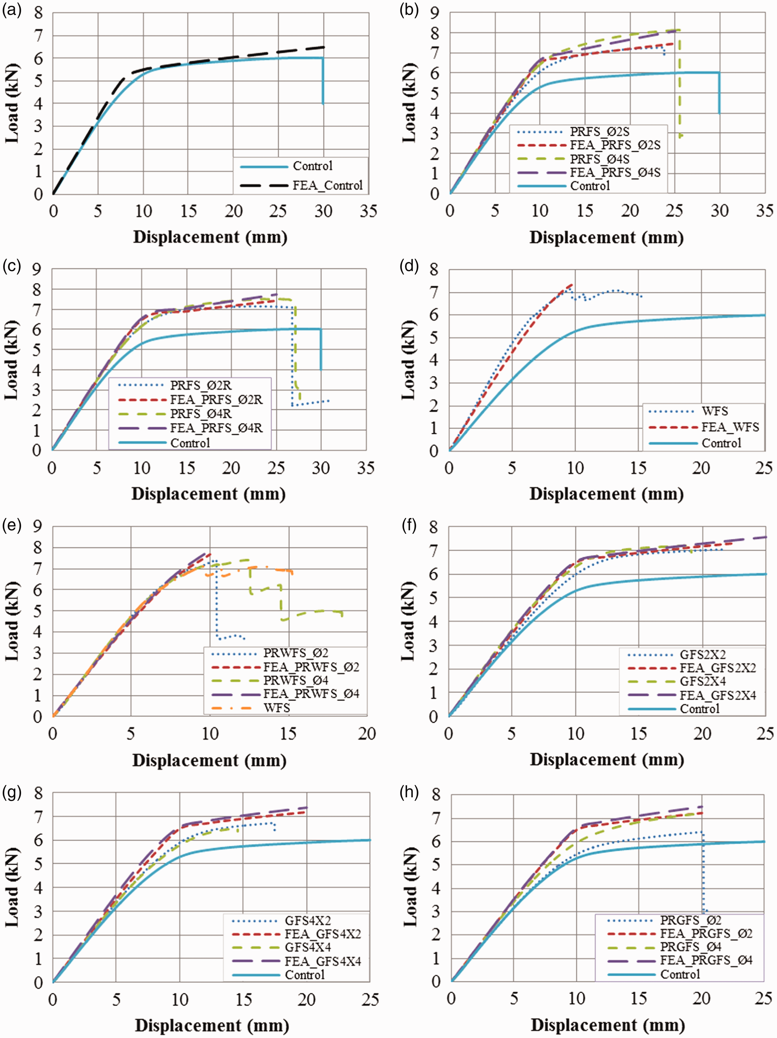

Perforated-foam core specimens
Figure 6(b) and (c) shows that the resin pins clearly improve the load bearing capacity and bending rigidity of the sandwich panels over the control specimen. This is due to the resistance of the resin pins against the inclination under the bending loads. Additionally, increased resin pin diameter increased the bending strength since increased resin pin diameter reduced the volume of the relatively softer PVC foam and enhanced the shear properties of the PRFS panels. The pins stiffened and strengthened the PVC foam against low shear loads, while the foam core supported the pins and prevented the premature shear failure. 30 The FEA successfully captured the initial stiffness and the post yield response of the PRFS specimens. PRFS_Ø2, 4R specimens failed due to compressive upper face sheet failure under the loading points while PRFS_Ø2, 4S specimens failed by core shear failure. The maximum increase in bending strength was 34%, observed in the PRFS_Ø4S specimen compared to the control specimen. PRFS_Ø2S, Ø4S specimens deflected at around 25 mm at failure load. Ultimate bending strength of the PRFS_Ø4R and PRFS_Ø2R specimens were increased approximately 24% and 18%, respectively, in comparison to the control specimen which was failed under 6 kN. In addition, the mid-point deflection at the final failure load for both the PRFS_Ø2R, Ø4R specimens was approximately 27 mm, while it was 30.2 mm for the control specimen. The bending stiffness values were also increased significantly. The increase in effective bending stiffness (EIeff) of the PRFS_Ø2S, PRFS_Ø4S, PRFS_Ø2R, PRFS_Ø4R beams was 25%, 29%, 14%, and 17% compared to control specimen, respectively.
Web-foam core sandwich specimens
Summary of the bending test results.
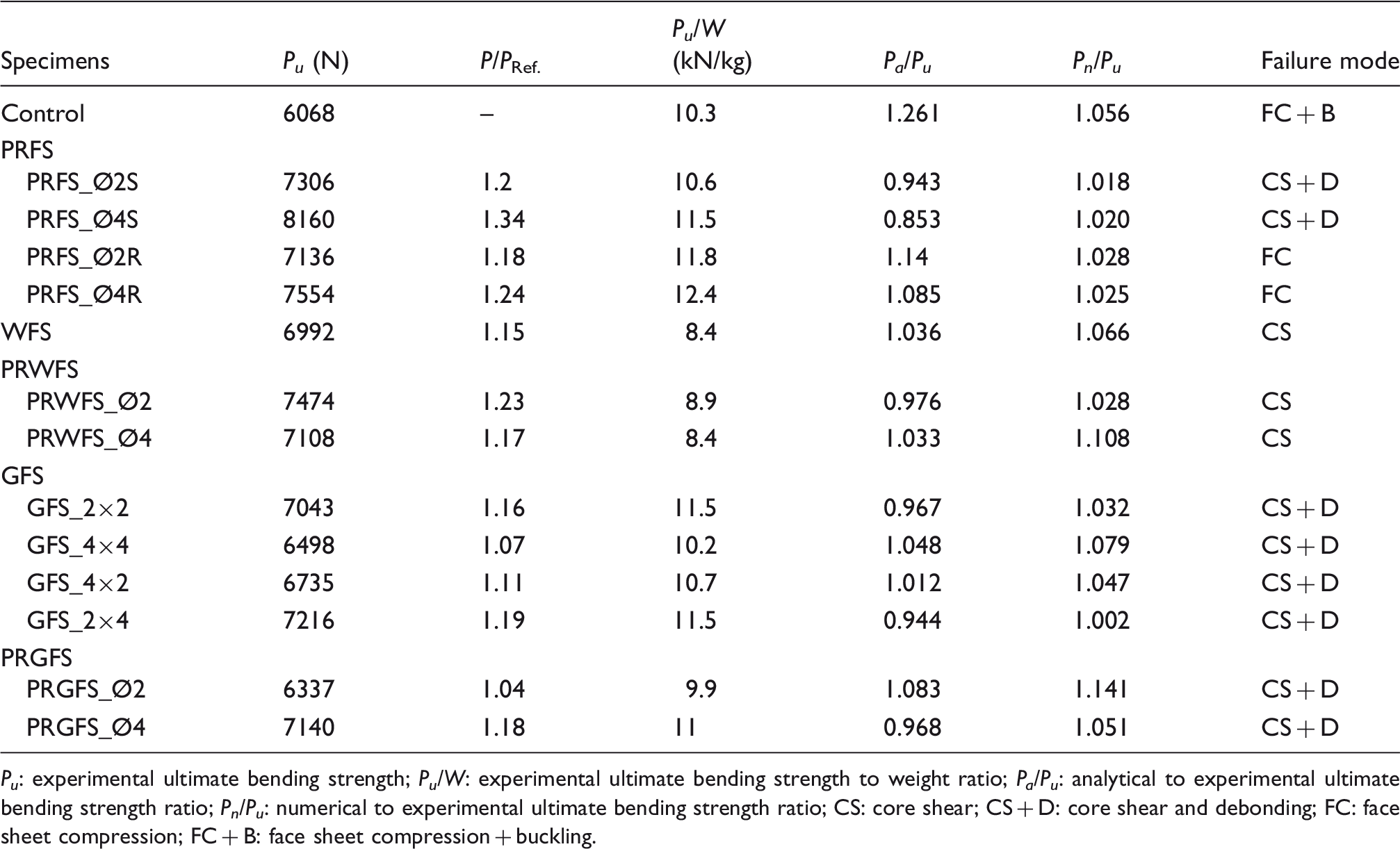
P u : experimental ultimate bending strength; P u /W: experimental ultimate bending strength to weight ratio; P a /P u : analytical to experimental ultimate bending strength ratio; P n /P u : numerical to experimental ultimate bending strength ratio; CS: core shear; CS + D: core shear and debonding; FC: face sheet compression; FC + B: face sheet compression + buckling.
Perforated-web-foam core sandwich specimens
The load–displacement curves of the PRWFS specimens are illustrated in Figure 6(e). All curves were almost linear up to 5 kN and followed by a non-linear segment. The non-linear portion was caused by the shear cracking of the foam core. The diagonal shear cracks initiated at the loading points and propagated through the foam core with an inclination angle of approximately 45°. The load bearing capacity of the PRWFS_Ø2 and PRWFS_Ø4 specimens was increased by 6.9% and 1.4%, respectively, compared to that of the WFS specimen. The pins slightly affected the bending strength of the WFS. The effective bending stiffness of the PRWFS_Ø2 and PRWFS_Ø4 specimens was 59% and 48% higher than that of control specimen, respectively. With increased applied loading up to failure, the FEA results diverged from the experimental curve in post yield region as in the case of the WFS specimens.
Grooved-foam core sandwich specimens
The load–displacement curves were almost linear until the development of shear cracks in the foam core material, as seen in Figure 6(f) and (g). Following the linear portion, the slopes were dropped sharply and a non-linear response was observed until the final failure. Debonding failure occurred in both top and bottom face sheets as shown in Figure 7(c) and (d). When the failure loads of GFS2 × 2 and GFS4 × 4 specimens are compared, it can be seen that increasing both the depth and the width of grooves leads to the weakening of the integrity of foam structure and hence reduces the bending strength of the sandwich beams (Table 3). The ultimate bending strength of the GFS2 × 2, GFS4 × 4, GFS4 × 2 and GFS2 × 4 specimens were found to be 16%, 7%, 11% and 19% higher than that of the control specimen, respectively. Among GFS samples, the highest increase in the effective bending stiffness value was observed in the GFS4 × 4 samples with a value of 22% compared to the control specimen. The resin filled into the grooves acted as a stiffener. The simulations also capture the damage evolution of the sandwich beams depending on the geometry of the grooves. As an example, FEA results and experimental damage modes of the GFS specimens are compared in Figure 8(a) to (d). The grooves were effectively introduced on the foam core surface to enhance the interaction of face sheet and the foam core for the GFS specimens. The shear stress around the grooves causes the development of crack at the tips of the grooves with the crack propagation diagonally towards the opposite side until it reaches the bottom interfacial area as shown in Figure 8(a) and (c). Moreover, an increase in the groove depth led to an increase in the amount of plastic strain values in the foam core (Figure 8(b)), whereas maximum shear elastic strain and maximum shear stress were constant for all the GFS specimens (Figure 8(c) and (d)). For the GFS2 × 4 specimens, the cracks progressed through the upper face sheet–foam interface and led to the face sheet-core debonding followed by the core shear failure. However, in the other GFS specimens, the shear cracks tended to pass around the grooves as illustrated in Figure 8(a).
FEA results and failure modes of GFS specimens (a) damaged GFS specimens, (b) plastic strain, (c) maximum shear stress and (d) maximum shear strain.
Perforated-grooved-foam core sandwich specimens
Figure 6(h) shows the load–displacement curve of the PRGFS specimens. The specimens showed a similar failure initiation and propagation behaviour to the GFS specimens (see in Figure 7(e) and (f)). Increasing the pin diameter had a positive effect on the bending properties (Table 3). However, a comparison of the GFS2 × 2 and PRGFS_Ø4 beams reveals that the effect of the pins on the test results was only around 6.6%. It points out that introducing the perforations into the grooved-foam core is not cost-effective due to additional operation effort and time. In comparison with the control specimen, the increase in effective bending stiffness values in PRGFS_Ø2 and PRGFS_Ø4 samples were limited to 8% and 13%, respectively. Good correlation was observed between FEA results and experiments in the initial loading stages. The small discrepancy observed in post yield region could be attributed to premature shear cracking in the foam core structure.
Load–strain behaviour
The load and mid-span longitudinal strain curves of the specimens are shown in Figure 9 (the longitudinal tensile and compressive strains are denoted as T and C, respectively). Measured maximum tensile and compressive strains at mid-span of the specimens are given in Table 7. The experimental results indicated that the strains both in tension and compression increased linearly at the initial stages of the loading. However, a higher tensile strain was measured in all the specimens. It confirms that the laminated composite face sheet has a lower modulus in tension than in compression, as given in Table 1. At a tensile strain of 3000 to 3500 micro strains, the strain gauge at the tension side of the specimens stopped functioning since the final failure was occurred. That strain level was only 16.6% of the maximum tensile strain of the glass fibre-reinforced composite face sheet. However, it was higher than the failure strain of the foam core in tension (see in datasheet of PVC foam).
41
This result confirmed that the specimens have not suffered face sheet damage under tension load.
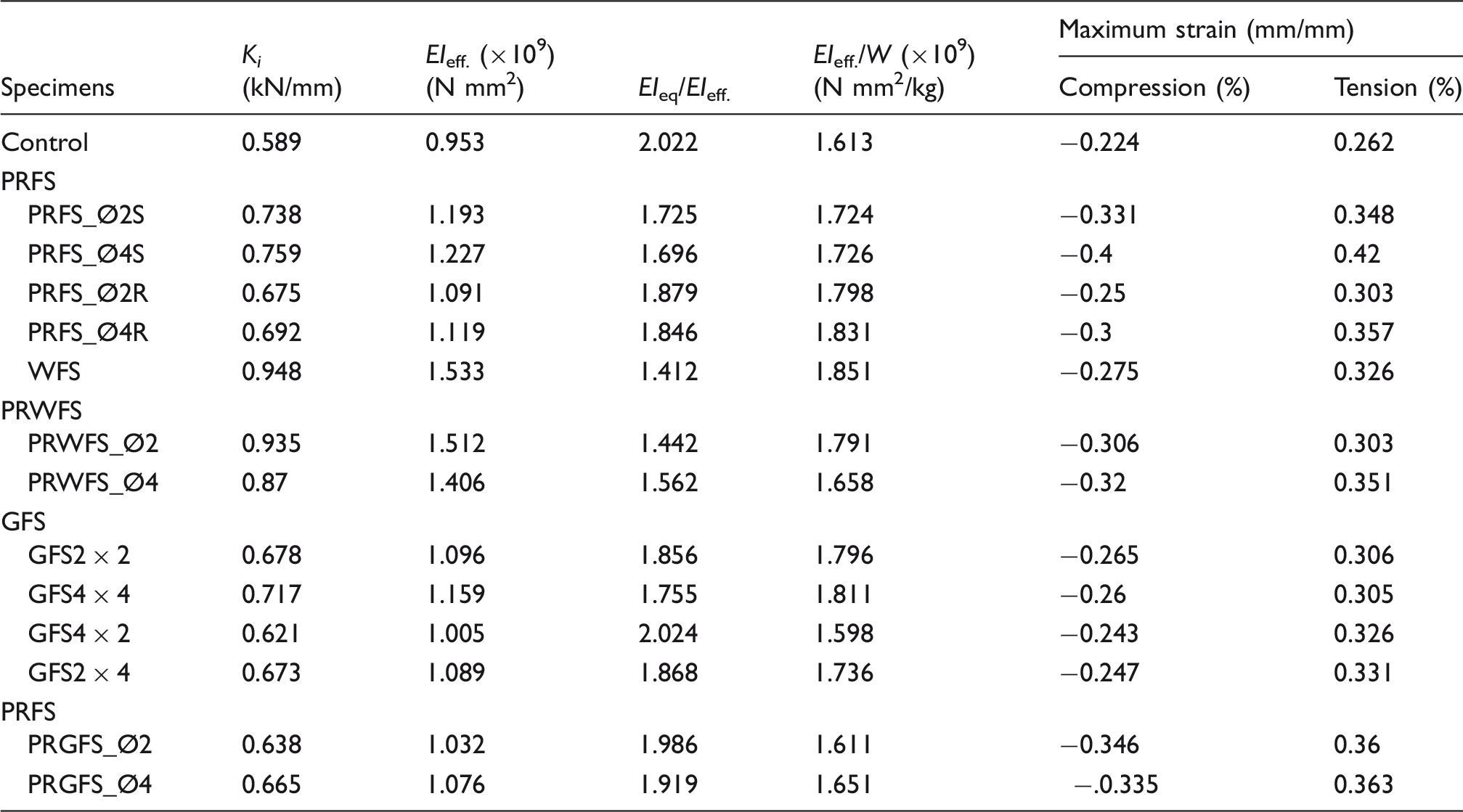
Mid-span load–strain behaviour of (a) PRFS_Ø2S,4S and control specimens, (b) PRFS_Ø2R,4R and control specimens, (c) WFS and PRWFS specimens, (d) GFS2 × 2, GFS4 × 4 and control specimens, (e) GFS2 × 4 GFS4 × 2 and control specimens and (f) PRGFS and control specimens. Initial and effective bending stiffness; equivalent to effective bending stiffness ratio and effective bending stiffness to weight ratios; and maximum compression and tension strain.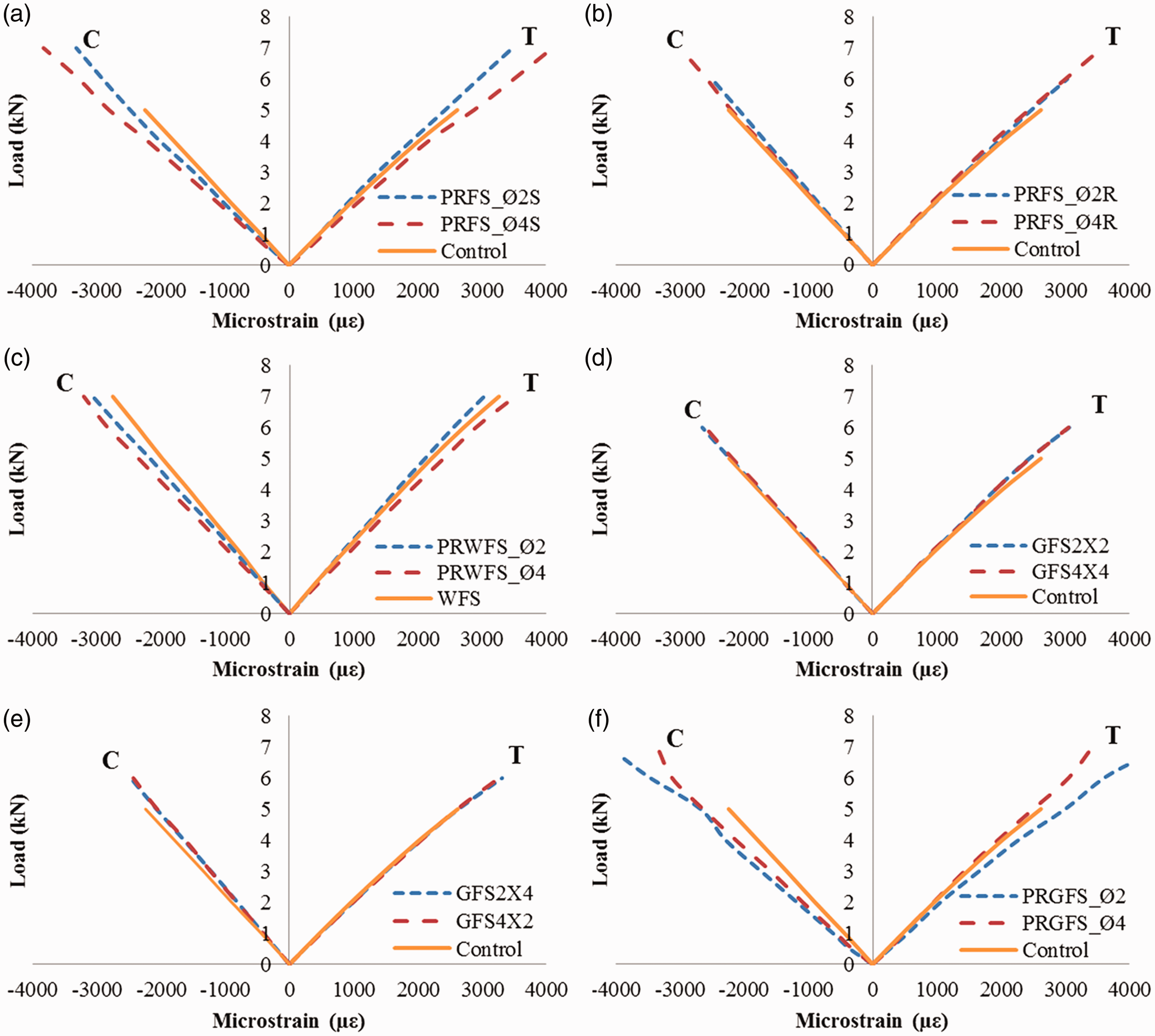
A slight non-linearity on the tensile side can be observed for the PRFS_Ø2S, Ø4S (Figure 9(a)), WFS (Figure 9(c)), PRWFS (Figure 9(c)), GFS (Figure 9(d) and (e)) and PRGFS (Figure 9(f)) specimens which resulted from the shearing of the core material. However, the strain curves of the PRFS_Ø2R, PRFS_Ø4R and the control specimens showed a linear behaviour up to final failure as seen in Figure 9(b). As expected, the specimens with the same groove cross-section (square or rectangular) exhibited similar behaviour (Figure 9(d) and (e)). In addition, the tensile strains of rectangular grooved specimens were higher than the square grooved ones. The presence of the webs or grooves caused higher compressive strains compared to control specimens and prevented the compressive failure of the upper face sheet.
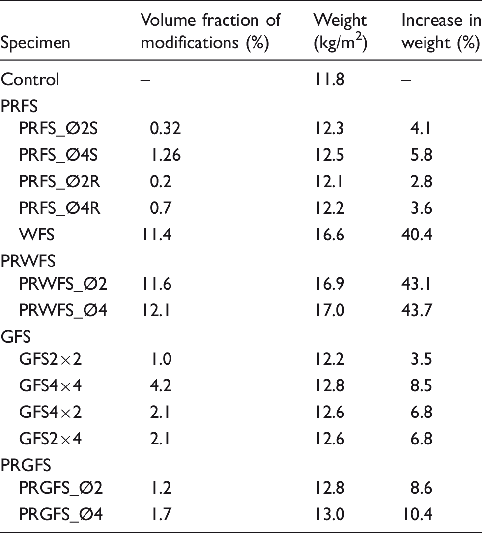
Weight penalty due to core modification
Weight measurements of the specimens.
Analytical study
Mechanical behaviour of the sandwich beams under 4PB was analytically predicted using the overall mechanical properties of the fibre-reinforced composite face sheets and the PVC foam core. Details are presented in this section.
Failure mode and ultimate bending load
Figure 10 shows the loading configuration and the cross-sectional geometry of the composite sandwich structure, where t
s
is the thickness of the face sheet material, t
c
is the thickness of core material, b is the width of the sandwich beam, h = t
c
+ 2t
s
is the total thickness of the sandwich beam and d = t
c
+ t
s
is the distance between the centre of the face sheets.
Four-point bending loading scheme and the size of cross-section of the composite sandwich beam.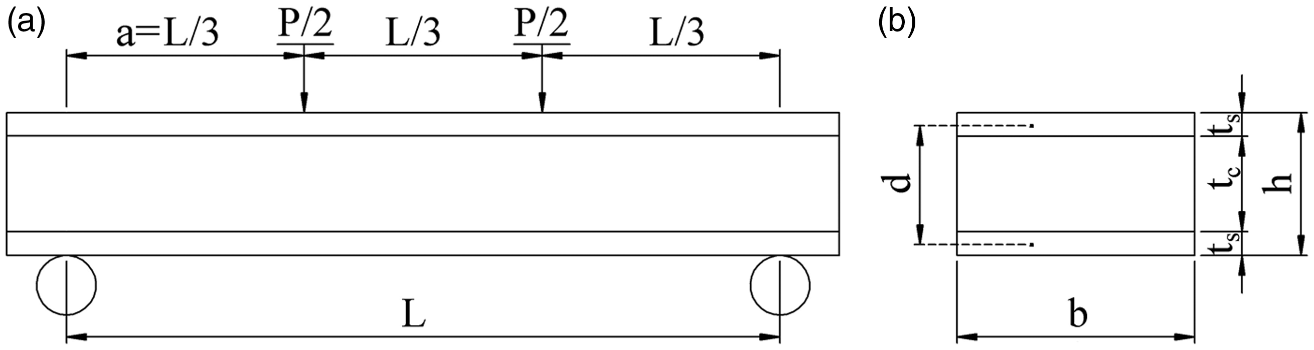
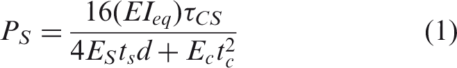
Failure mode and the corresponding load carrying capacity of sandwich beams can be determined by the geometry, mechanical properties of the face sheet and the core materials, and the loading configuration. The core shear failure occurs when the shear strength of the core is exceeded.
58
The shear failure load (Ps) can be predicted by equation (1)
49

Analytical formulations of equivalent bending stiffness and shear stiffness.
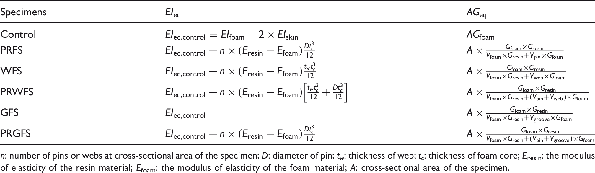
n: number of pins or webs at cross-sectional area of the specimen; D: diameter of pin; t w : thickness of web; t c : thickness of foam core; Eresin: the modulus of elasticity of the resin material; Efoam: the modulus of elasticity of the foam material; A: cross-sectional area of the specimen.
Face sheet compressive failure occurs if the bending stress of the face sheet exceeds its compressive bending strength and the failure load due to bending (Pb) of a sandwich beam can be predicted by equation (4)
49
Figure 11(a) presents the analytically predicted (P
a
), experimental (P
u
) and numerical (P
n
) maximum bending load values. The deviation between the theoretical and experimental results of the ultimate bending loads varied from 1.15% to 26.05%. The largest deviation between the experimental and analytical results in the ultimate bending strength was 1.58 kN, which occurred for the control specimen. This could be due to the combined effect of the face sheet compression/buckling and core crushing under loading point. The large discrepancy in PRFS specimens could be due to the plastic deformation of pins which was not considered in the analytical formulations. In general, classical failure models can estimate the shear failure loads within 30% and bending failure loads within 20% of the experimental results. This underestimation may be due to complex state of stress at the contact location of loading point and upper face sheet and debonding between the face sheet and the core which were not accounted for in the analytical calculations.
61
The deviation between the numerical and experimental results of ultimate bending loads varied between 0.2% and 14%. FEA results provided a better agreement with the experiments than the analytical ones (see Figure 11(a)).
(a) Comparison of analytical, experimental and numerical results of ultimate bending strength, (b) initial bending stiffness, (c) effective bending strength and (d) specific effective bending stiffness of sandwich beams.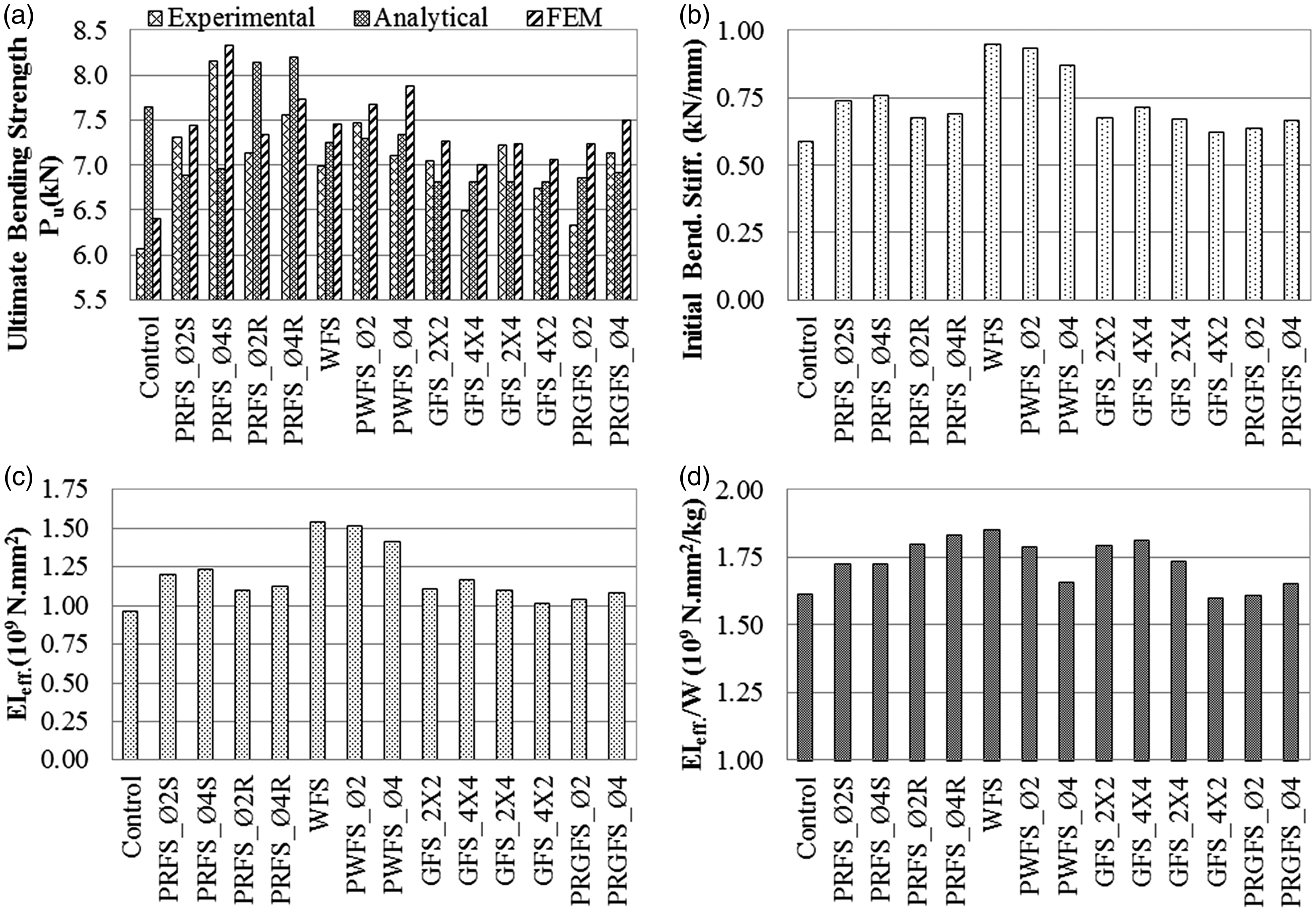
The bending load-bearing capacities of the PRFS, GFS and PRGFS sandwich beams increased by 4% to 34% compared to that of the control specimen (Table 3). Ultimate bending load of the PRWFS_Ø2 and PRWFS_Ø4 specimens were increased by 7% and 2%, respectively, in comparison with the WFS specimen. These findings revealed that core machining configurations improve the ultimate bending load of marine sandwich beams.
Furthermore, specific bending loads of the sandwich beams (Pu/W) are given in Table 3. It should be noted that the weight gain of the WFS specimen can be justified depending on the specific application and performance requirements since the web cores can be easily shaped to produce curves (bendability) for carina and broadside in boat hulls where increased stiffness is needed. 38 On the other hand, the plain foam core panels may be used in sandwich deck floor and partial bulkhead panel's interior applications in boat construction. Except for the GFS4 × 4 and PRGFS_Ø2 specimens, the core modified specimens yield more specific bending strength than the control specimen in which the weight penalty can be tolerated in critical applications where an increased bending performance is required.
Mid-span deflection
The first-order shear deformation theory was used to determine the load–displacement behaviour of a simply supported composite sandwich beam under 4PB as illustrated in Figure 10, in which the total displacement is the sum of the bending and shear deformation
62
Taking into consideration the core modifications, the equivalent shear stiffness of the modified foam core (AGeq) can be expressed as35,56

Comparison of analytical and experimental mid-span deflections.
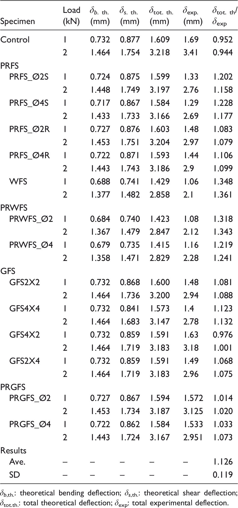
δb,th.: theoretical bending deflection; δs,th.: theoretical shear deflection; δtot.th.: total theoretical deflection; δexp: total experimental deflection.
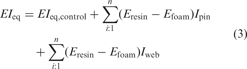
Bending stiffness
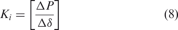
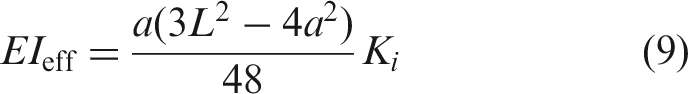
Initial bending stiffness, Ki, of the specimens was obtained from the slope of the mid-span load–displacement curves and are given in Figure 11(b). The stiffness Ki is related to the applied load and the corresponding mid-span deflection of the sandwich beams. Based on this equation, it can be stated that the initial stiffness increased with increasing the slope of the curve. The initial stiffness then can be used to obtain the effective bending stiffness based on the deflection formulation by equations (8) and (9)
63
The initial and effective bending stiffness, equivalent to effective bending stiffness ratio and effective bending stiffness to weight ratio are presented in Table 7.
The WFS specimen had the highest initial bending stiffness due to the presence of the webs (Figure 11(b)). A similar result was reported by Wang et al. 35 The initial bending stiffness of the PRWFS specimens decreased with increasing the diameter of the perforations. Additional drilled holes could increase the load transfer capability but causing further deflection to the specimens in elastic region. The equivalent stiffness values were calculated for all the specimens according to the analytical formulations given in Table 5. The WFS and PRWFS specimens had apparently higher effective stiffness compared to the PRFS, GFS and PRGFS specimens as seen in Figure 11(c). However, their equivalent stiffness values were closer to their effective stiffness mainly because of the insignificant influence of the shear deformation. Moreover, the effective stiffness of the WFS specimen was 60.9% higher than that of the control specimen. It was observed that the grooves and perforations on the foam core made a positive contribution between 5% and 29% to the effective stiffness of the sandwich beams. The equivalent stiffness was significantly higher than the effective stiffness values for the PRFS and GFS beams, in which the differences ranged from 69.6% to 102.4%. As seen in Figure 11(d), almost all modifications contributed to the specific stiffness where the WFS specimen achieved the highest.
Conclusions
In the present work, bending properties of the marine composite sandwich beams with different core modifications under 4PB were investigated experimentally, analytically and numerically. The experimental results showed that core modifications, i.e. webs, grooves and/or perforations, provided a significant increase in the bending strength of the composite sandwich beams. The perforations were more effective for improving the ultimate bending strength than the grooves. Different failure modes of the tested sandwich specimens indicated that the flexural behaviour of the marine sandwich composites may be manipulated by core machining configurations.
Analytical formulations were used to calculate the equivalent and effective bending stiffnesses. The effective bending stiffness was overestimated due to the fact that shear deformations of the sandwich beams could not be taken into account by the theory used. The flexural responses were also numerically predicted using ANSYS software based on the isotropic hardening plasticity model representing the foam core behaviour. FEA simulations accurately captured the initial and post yield flexural responses of the control, PRFS, GFS and PRGFS specimens. Due to linear elastic approach of web structures under flexural loading, a high deviation following the elastic region was observed in the case of WFS and PRWFS specimens.
Local indentation of the face sheets into the core material under the loading and support rollers is an inherent drawback of three-point bending and 4PB tests. Therefore, there is a need for further investigation regarding the effect of the test method (e.g. a panel with a distributed pressure loading) on the failure behaviour of such sandwich composites.
Footnotes
Acknowledgements
The authors would like to thank Numarine Yachts Inc. and GCG Marine Inc. for several useful discussions on VARTM manufacturing process.
Declaration of Conflicting Interests
The author(s) declared no potential conflicts of interest with respect to the research, authorship, and/or publication of this article.
Funding
The author(s) disclosed receipt of the following financial support for the research, authorship, and/or publication of this article: This project was funded by Balıkesir University Scientific Research Projects Department (BAP.2016-03/06).