
Abstract
To increase the strength and to reduce the wear rate of the copper composite that used as a solid self-lubricant materials, Cu/10MoS2/ (0, 0.2, 0.4, 0.6, 0.8, and 1 wt.% graphene nanosheets) hybrid matrix nanocomposites were fabricated using the electroless copper precipitation process followed by the cold pressing and sintering in a hydrogen atmosphere furnace with a double-heating rate cycle. The microstructure of the as-received powders, as well as the produced samples, was examined using the scanning electron microscope. The chemical composition of the fabricated composites was evaluated by the energy dispersive spectrometry analysis. The effect of the graphene nanosheets (wt.%) addition on the densification, the hardness, the adhesive wear rate, the wear mechanism, and the coefficient of friction was investigated. The low heating rate of 5℃/min was the best for the fabrication process. The microstructure of the composites reveals the good distribution of the (graphene nanosheets and MoS2) in the copper matrix and good adhesion between graphene nanosheets and the (Cu-10MoS2) matrix as well. The 0.4 wt.% graphene nanosheets composite exhibits the highest hardness, the lowest wear rate, and the lowest coefficient of friction. The adhesive regions were dissipated by increasing the graphene nanosheets up to 0.6 wt.% then increased.
Introduction
Solid lubricants are materials used to increase the service time of machinery components, which get exposed to high friction and severe conditions, where oil and grease are difficult to be used. They may exist in the form of semi-fluid lubricant materials like greases and fluid lubricant materials like oils. Reinforcing copper with solid lubricant materials such as graphite and molybdenum disulfide made it used widely in many applications like bearings, bushings aircraft, and automotive accessories. It also made it used in electrical brushes for its low friction coefficient and high wear-resistant properties.1–5
Graphite (C), boron nitride (BN), tungsten disulfide (WS2), calcium fluoride (CaF2), Lead–Tin–Silver (Pb–Sn–Ag), and molybdenum disulfide (MoS2) are the most commonly used solid lubricant materials. Molybdenum disulfide is an attractive self-lubricating material due to its extremely low coefficient of friction (COF). It is similar in its structure to the graphite, where it has the lamellar structure formed by many stacked layers. Its microstructure shows that each sheet is composed of a plane of molybdenum atoms embedded between two planes of sulfur atoms. The covalent bonds between the S-Mo-S within a layer are very strong, while the staked strength between every two neighboring layers produced by the van der Waals force is comparatively small. Therefore, the layers can slip with ease, resulting in a low COF, which gives molybdenum disulfides its lubricating properties.6,7
Many researchers tried to enhance the properties of the solid-self-lubricating materials and increase their life by reinforcing those using ceramic materials, but this affects the COF and leads to increase it. Reinforcing solid self-lubricating composites by ceramic materials such as SiC or Al2O3 attributed to increase its hardness, but the presence of it in the matrix leads to destroying the surface of the protected parts through scratching it. As it scratches the surface of the protected parts, the COF increases and consequently maybe leads to an increase in the wear rate.8,9,10
To solve this problem and maintain the strength of the composites, we thought to reinforce composites with graphene. The presence of graphene in the matrix will increase the strength and keep the parts in a good situation without any scratches that happen from ceramic materials.
Graphene, as a two-dimensional layer material, has a micro surfaces area and a nanothickness. It has many striking properties, which make it used in various applications that include transparent electrodes, solar cells, wearable devices, and catalysis. It is characterized with its high transparency (97.7% transmittance in the visible spectrum), high thermal conductivity (3 × 10³ W/m K) at room temperature, high electrical conductivity (∼104 Ω−1 cm−1), high Young's modulus (1.1 TPa), and high-specific surface area (2630 m2/g).11–15 Zhang 16 studied the effect of reinforcing copper matrix by different weight percentages of graphene through the Electrostatic Self-Assembly technique on the tribological properties. The antifriction performance of the fabricated composites could be improved significantly by adding nanographene platelets (GNPs) up to 0.4 wt.%, where the composites achieved the best performance at this percentage. During the wear test, the GNPs formed a solid lubricant film on the surface of the composites and lead to reduce the direct contact between the Cu matrix and steel ball which reduces the COF of GNPs/Cu composites. Chen et al. 17 investigated the effect of graphene content on the COF of the copper matrix composite. The results revealed that the COF of copper is dramatically reduced by increasing the graphene content. It is observed that the COF of the composite with 4.0 vol.% was about 0.25, which was 60% lower than reference copper that is 0.6.
Copper metal matrix composites can be produced by many methods, include extrusion, casting, and powder metallurgy techniques. To get a homogeneous distribution for reinforcements and good interfacial bonding at a temperature less than the melting point temperature of the matrix as well as minimize raw materials consumption and near net shape character, the powder metallurgy technique was the best choice.18–21
This experimental work concentrates on studying the influence of the heating rate on the bulk density of the Cu-MoS2/GNs nanocomposites by the powder metallurgy method. Also, studies the effect of the graphene weight percentage on the microstructure, hardness, wear rate, wear mechanism, and the COF.
Materials and methods
Materials
In this investigation, the as-received graphene nanosheets (GNs) and molybdenum disulfide powder (MoS2) materials are used as reinforcements for the copper matrix. The MoS2 powder of the 1–0.5 µm particle size is supplied by the DOP ORGANİK KİMYA SAN.VE TİC. LTD ŞTİ company, while the graphene powder of the 2–10 nm thickness is supplied from (ACS Material, LLC). The electroless deposition process is used for precipitating the silver and copper metal on the surface of the MoS2 and GNs particles. The coating by silver is for facilitating the copper deposition on surfaces of the MoS2, and GNs particles. The process is established from bath contains 472 ml water, 0.944 g (AgNO3) of 99.97% purity, ammonia 33% (Ph = 11), and formaldehyde of 38% concentration (30 ml/100 ml water) to precipitate 3 wt.% Ag. The chemical composition bath for precipitating copper consists of 70 g/l (CuSO4·5H2O), 170 g/l (KNaC4H4O6·4H2O), 50 g/l (NaOH), and 200 ml/l (CH2O) that used as a reducing agent of copper ions.18,19
Preparation and fabrication of Cu/MoS2 /GNs composites
The MoS2 and GNs powders are cleaned by stirring them in 10 wt.% (NaOH) and acetone for 1 h, respectively. Then, the powders are coated with 3 wt.% silver from a bath containing 2 g/l silver nitrate and 11 pH. 400 ml/l formaldehyde gets used to reduce the silver metal ions. 10 wt.% MoS2 is coated with 90 wt.% copper by the electroless deposition process to prepare the Cu nanomatrix composite,18,19 that is, reinforced with different percentages of GNs of 0.2, 0.4, 0.6, 0.8, and 1 wt.%. Before proceeding to the electroless copper coating process, the MoS2 and the GNs for each composite sample are mixed together properly using a pestle and mortar for 30 min. This is performed to ensure their homogenous distribution in the copper matrix. The produced Cu-MoS2/GNs nanocomposites powders are heated in a tubular oven at 500℃ for 1 h in a hydrogen atmosphere for reducing the copper oxide that gets formed during the electroless deposition, into Cu. Also, that leads to an increase in the contact area between the reinforcements and the copper matrix, where the insulated oxides have been removed. The composites are cold-pressed by applying a load of 900 MPa in a die of 12 mm diameter, 10 mm sample height. The compacted composites are consolidated under a hydrogen atmosphere at 1000℃ for 120 min with two heating rates, as shown in Figure 1.
Heating cycles of the sintering process of Cu/MoS2/X GNs composites. GNs: graphene nanosheets.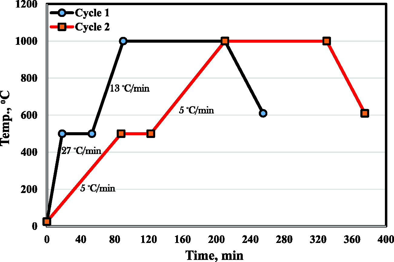
Evaluation of sintered samples
The density of sintered composites is evaluated by the Archimedes method according to the test standard ASTM B962-14. After preparing the solid composite surface by the grinding and polishing processes, the Quanta FEG250 (FE-SEM) is used to investigate the microstructure. X-ray diffraction (D8 XPORT) is used to characterize the phase composition at a 2θ scanning rate and the distribution of 10°–100°.
Vicker's hardness values of the prepared composites are measured using the macro-hardness tester (5030 SKV, England). The conditions of the measuring process were 5 kg load, and 15 s dwell time. Four readings for each sample have proceeded.
A dry adhesive wear test of the composites is accomplished by utilizing a pin-on-ring test machine to investigate the wear rate, the COF, and the wear mechanism. The disc was made of 316 L stainless steel with a hardness of 65 HRC. 0.7 m/s speed, (10, 20 and 30 N) load, and 10 min times represent the test conditions. The selection of test conditions was based on the evaluation of the copper matrix in previous studies.16,22 The test is performed at 25℃ atmosphere temperature. The test is repeated three times for each sample. The wear rate is specified from the weight loss and the wearing time (g/min). The wear mechanism of the worn surfaces is evaluated by utilizing the SEM (Quanta FEG250). The COF at different loads (20 N and 30 N), and 300 rpm for 10 min has proceeded.
Results and discussion
Materials characterization
Figure 2(a) and (b) shows the morphology of the GNs, and MoS2 utilized powder materials at high magnification, in addition, Figure 2(c) and (d) for the Cu coated GNs and MoS2. As shown, graphene takes the shape of the layer with nanothickness and large surface area, and the molybdenum disulfide has irregular plates shape. The GNs and MoS2 are completely coated with Cu, as it is shown in Figure 2(d), respectively.
SEM (BSE) micrograph of (a) graphene nanosheets (GNs), (b) molybdenum disulfide (MoS2), and (c and d) Cu-coated GNs and MoS2. GNs: graphene nanosheets.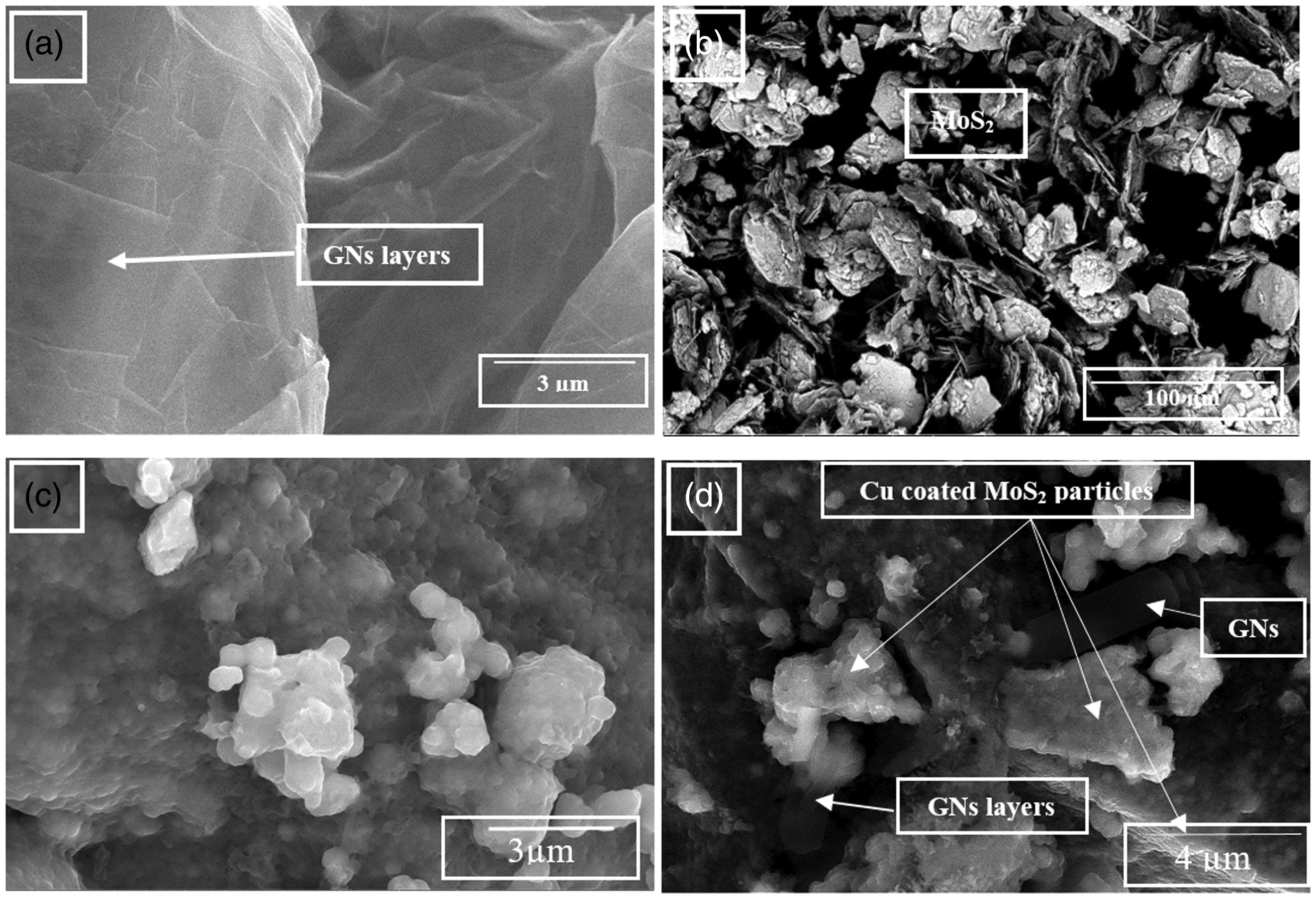
Sintered samples characterization
Sintered composites densification
The relative density of the sintered nanocomposites at the two heating rates is shown in Figure 3. It is evident from the figure that, the composites, which are sintered by the low heating rate (5℃) exhibit the highest relative density. The heating rate of the sintering process is one of the most important parameters of the powder metallurgy technique, where it affects the densification of the sintered composites. The low heating rate allows the internal gases to escape during the sintering process, where the high heating rate makes the outer surface of the sintered material to consolidate before the core of the sample, where the outer porosities are closed, and this restricts the inside gases to escape, consequently swelling of samples takes place. In addition, the low heating rate improves the adhesion between the different constituents of the composites, which finally increases the densification. Also, it gives a chance of the particles of different constituents to interact with each other on the grain boundary, leading to good interaction and densification.
Relative density of the consolidated nanocomposites at two heating rates.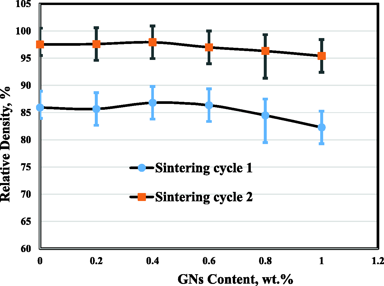
The effect of the heating rate on the density and properties of the sintered series 300 stainless steel was investigated by Tosangthum et al. 23 The results revealed that the sintered materials, which were heated at a low heating rate head to have higher sintered densities. Also, the effect of heating rates on the crystallite size and densification behavior of Al-MWCNT nanocomposite via Spark Plasma Sintering was studied by Singh et al. 24 The results manifested that the higher heating rate and lower sintering temperature attributed in synthesis composites with finer crystallite size, whereas the higher sintering temperature and the lower heating rate resulted in higher densification.
Regardless, the density of the GNs (2.25 g/cm3) reinforcement is lower than the density of the Cu (8.9 g/cm³) and MoS2 (5.06 g/cm³), the figure demonstrates that the densities of the sintered composites are enhanced by increasing the percentage of the GNs up to 0.4 wt.% GNs. Achieving maximum density value at 0.4% GNPs composite may be due to the full homogeneous dispersion of GNs in the Cu/MoS2 matrix.
Figure 4 illustrates the images of the sintered nanocomposites at the high heating rate (27℃/min) and the low heating rate (5℃/min), respectively. It is obvious that samples sintered at the high heating rate have swelled. The swelling action may be produced as a result of gas retention inside samples during the sintering process, where the high heating rate allows the outer surface of samples to consolidation before the core. On the other hand, samples sintered by the low heating rate (5℃/min) have a good chance for the internal gases to escape out of samples, so good densification was achieved.
Images of sintred samples at the high heating rate 27℃/min and the low heating rate 5℃/min.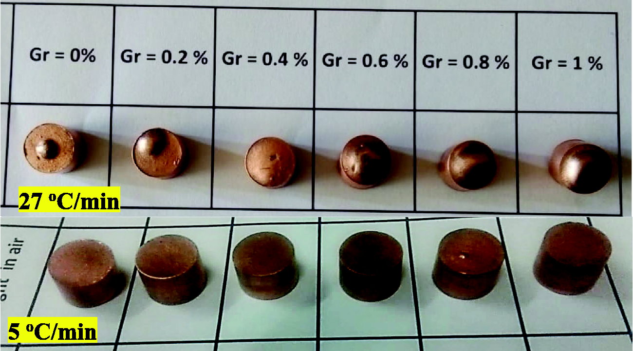
Fabricated composites microstructures
The microstructure of the nanocopper matrix that integrated with 10 wt.% MoS2 and 0, 0.2, 0.4, 0.6, 0.8, and 1 wt.% GNs are shown in Figure 5. The composites show good sinterability. Three phases are observed, which are gray Cu, white gray MoS2, and the changeable black GNs reinforcement. The microstructure of samples that contain GNs and MoS2 shows that both GNs and MoS2 particles have a plate-like shape. All the composites show high relative density so that no porosities are detected. The electroless copper deposition on the MoS2 and GNs surfaces leads to a formation of nanocopper particles that enhance the non-wettability between the constituents, consequently, no pores or voids are produced. No grain boundaries are formed between the copper particles that means a complete reduction of oxides from the precipitated copper oxide and also suitable fabrication conditions. It is clear from the microstructures that both MoS2 and GNs are distributed in a homogeneous manner in the Cu matrix, as well as good adhesion between all the constituents has been achieved. The good adhesion may be due to the coating process, which increases the contact angle between the matrix and reinforcement. Also, heat treatment of the composite powders at 500℃ in the hydrogen atmosphere furnace gets rid and eliminates any formed oxides from a deposited layer of copper. To emphasis the particle size of the MoS2 powder, it was characterized by measuring its largest dimension on the surface area, as shown in Figure 5(g) and (h). Some agglomerations of the GNs in the fabricated 0.8 and 1 wt.% GNs samples are revealed in Figure 5(i) and (j). Because the graphene is very thin (has 2–10 nm thickness) and has a big area, the probability of agglomerating and stack action increases by increasing its percentages. Also, intermetallic that happens between the Cu and MoS2 is observed.
SEM (BSE) micrograph of the (a) Cu/MoS2 matrix, (b) reinforced 0.2 wt.% GNs, (c) 0.4 wt.% GNs, (d) 0.6 wt.% GNs, (e) 0.8 wt.%GNs, and (f) 1 wt.%GN. (g) and (h) are illustrations of size determination for MoS2 and GNs particles at 0% GNs and 1 wt.% GNs, respectively. (i) (0.8 GNs) and (j) (1 GNs) for discover any GNs agglomerations in the 1 wt.% GNs sample. GNs: graphene nanosheets.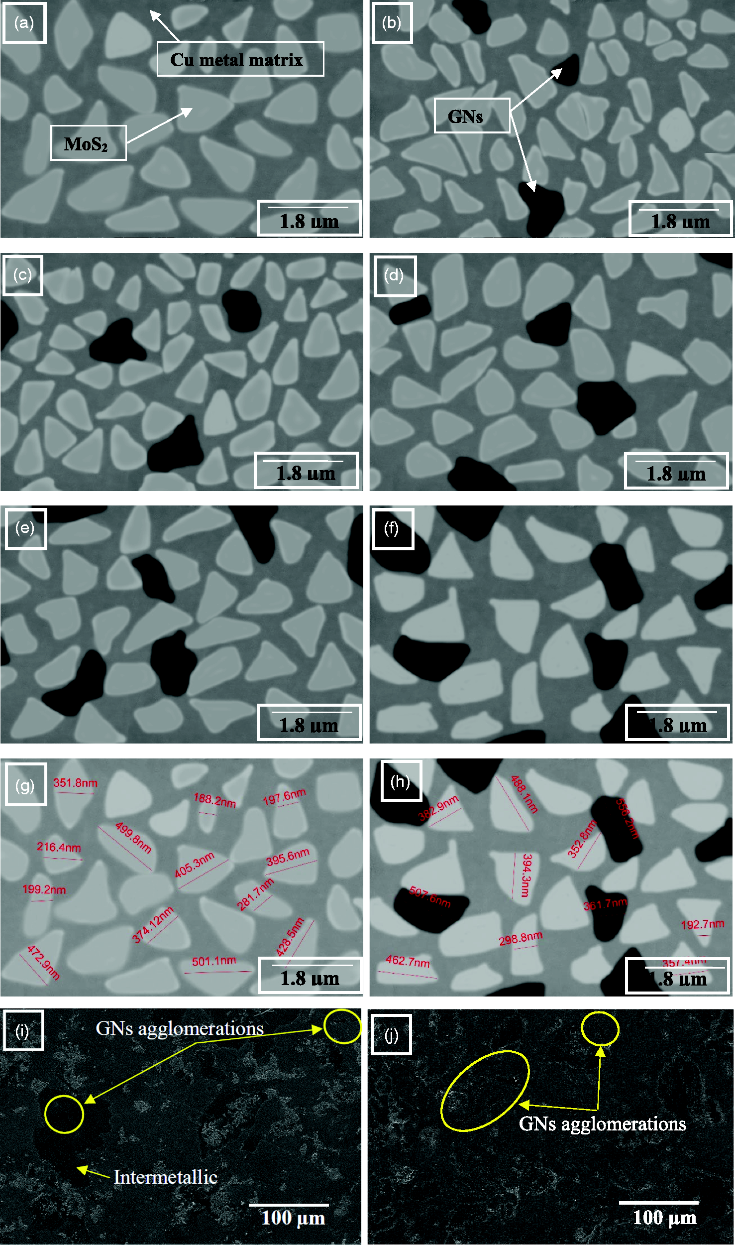
Figure 6 shows the chemical composition of the EDAX analysis of the sample, which contains 1 wt.% GNs. The analysis shows that the analyzed region contains 34.7 wt.% copper, 22 wt.% molybdenum, 40.68 wt.% sulfur, and 2.62 wt.% graphene that in the form of carbon. This is a good indication of the homogenous distribution of the MoS2 and the GNs all over the copper matrix.
EDAX analysis Cu/MoS2 matrix reinforced 1 wt.% GNs. GNs: graphene nanosheets.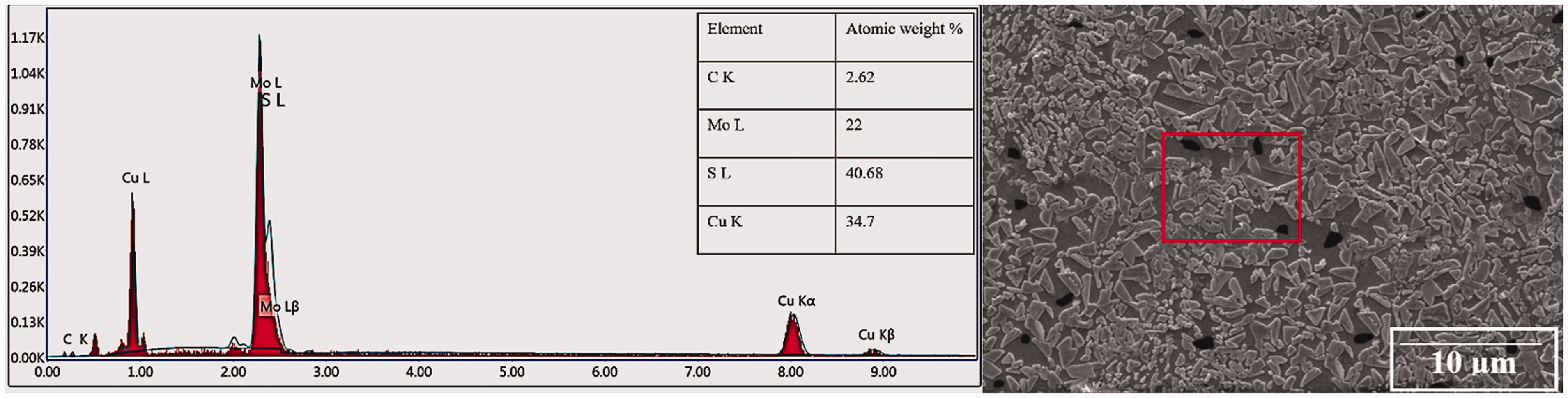
To check the chemical composition, the crystal structure, and purity of the used raw materials that are GNs, MoS2, and Cu, as well as the fabricated composites that have 0 and 1 wt.% GNs, the X-ray diffraction analysis shown in Figure 7 was performed. The analysis confirmed the purity of the as-received raw materials, where no impurities were detected. On the other hand, it shows that there is a reaction established between the Cu and the MoS2 during the sintering process leads to produce a new intermetallic compound that is copper–molybdenum sulfide CuMo2S3.
X-ray analysis of the as-received materials and the (0 and 1 wt.% GNs) fabricated nanocomposites. GNs: graphene nanosheets.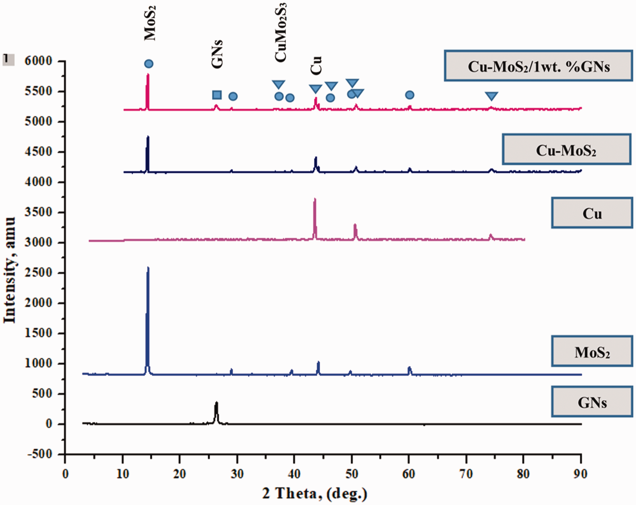
Mechanical properties
Hardness measurement
Figure 8 shows the influence of the GNs weight percentages on the hardness of the Cu/MoS2 composite. It is obvious that the hardness value increases gradually by increasing the GNs content up to 0.4 wt.%, then it gets decreased. The increase in hardness with the addition of 0.4 wt.% GNs to the copper matrix may be attributed to the good distribution, and the good adhesion of the graphene layer with the matrix that holds the particles of copper and MoS2 together and prevents the indenter of the macro-hardness to penetrate in the composite matrix. Decreases the hardness of the Cu/MoS2 composite at percentages over 0.4 wt.% GNs may be related to producing some agglomerations of the GNs layers, as shown in Figure 5(i) and (j). Also, it may be related to changing the ordination of GNs in the matrix as a result of increasing its percentages. As the results show, the addition of 10 wt.% MoS2 to the copper matrix improves its micro-hardness from 67 HV of Cu to 89 HV with a percentage of 32.83%, on the other hand, the addition of 0.4 wt.% GNs of the Cu/ MoS2 improves its micro-hardness from 89 HV of Cu to 140 HV with a percentage of 57.3%. Regardless, decreasing the hardness of the matrix at percentages over 0.4 wt.% GNs, it is still greater than the hardness of the matrix.
Hardness measurements of the fabricated composites.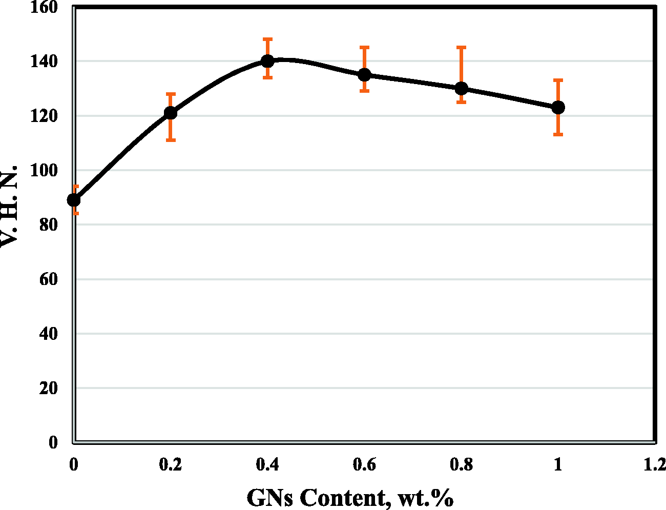
Composite wear rate
Copper/GN composite is one of the few self-lubricate studied metal matrix composites, and using the graphene as a reinforcement for the copper matrix is a shot seeking further improvements in mechanical, electrical, and thermal performance. Graphene is considered a novel solid lubricant material because of its excellent performance as observed in previous studies.25–28 Figure 9 demonstrates the influence of the graphene contents on the wear rate of the Cu/MoS2 composite at different loads. Two phenomena are observed from the figure; the first is that the wear rate of the Cu/MoS2/GNs composites increases with increasing the load, and the second is that the wear rate decreases with increasing the graphene percentages up to 0.4 GNs. As the figure shows, the effect of the applied load is increased gradually by increasing its value, but this is not clear at small values 10 N and 20 N. At small-applied loads, the contact area between the pair of contact was minimum, so that the effect of it on the wear rate was not high. By increasing the load up to 30 N, the pressure increased and the COF, respectively, and consequently the wear rate increased. The results demonstrate that the wear rate of the Cu/MoS2 composite decreases from 0.02013 g/min to 0.00559 g/min as a result of reinforcing it with 0.4 GNs wt.%. Reinforcing the Cu/10MoS2 composite matrix with GNs leads to a decrease in the volume percentage of the MoS2 gradually, and this reduces the number of sliding MoS2 layers and consequently minimizing the wear rate. Reinforcing the copper matrix with layers of GNs increased the hardness as Figure 8 showed, consequently decreasing the wear rate.
Wear rate of the fabricated nanocomposites.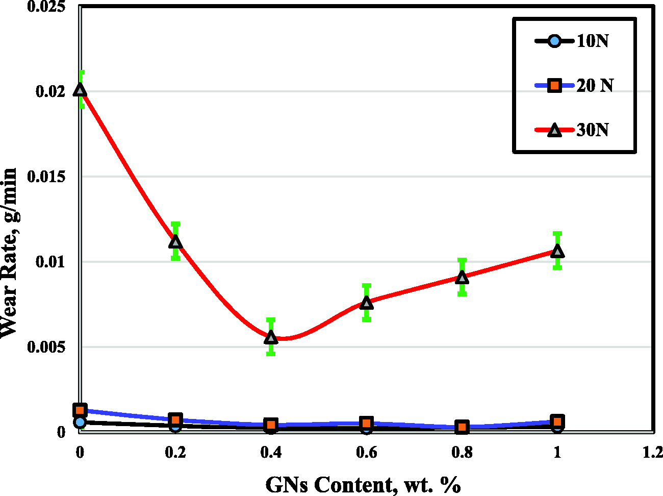
The wear rate of the Cu-10MoS2/GNs nanocomposite increases at percentages over 0.4 wt.% GNs that may be due to producing some agglomeration of the GNs, as shown in Figure 8(i) and (j), and this leads to a formation of GNPs, which is a multiple of graphene layers.29,30 Production of multilayers graphene qualifies it with the properties of graphite, which facilitate the sliding among the GNs layers and, consequently increases the wear rate. Also, it increases the COF, where it reduces the smooth motion among the frictional parts.
Wear mechanism
Figure 10 illustrates the SEM images of the adhesive wear test of the composites at 30 N normal force. As it is obvious from the images, sliding of MoS2 layers among each other, grooves, ploughing, adhesive regions, and plastic deformation are noted on the worn surfaces. Due to the effect of tribological stress, MoS2 spread on the worn surface of the samples (a), and the same action is observed at high percentages of GNs more than 0.4 wt.%. The graphene sheets grip the particles of copper with the particles of MoS2, so, the spread action is dissipated with the increasing of GNs up to 0.4 wt.%. The presence of the GNs distribution in a good manner has increased the rigidity of the copper matrix composite and leads to produce a smooth motion between the composite material and the sail-less steel. The spread action of the MoS2 covers a big area of the sample surface, which may lead to a decrease in the COF all over the friction surface area. Samples (b, c, and d) show the highest grooves and ploughing. It can be seen from the images that the worn surfaces of the samples (b, c, and d) are relatively smooth in comparison with the worn surfaces of the samples (a, e, and f), which may be attributed to the high hardness as a result of reinforcing them with suitable percentages of GNs. By increasing the percentages of the GNs, the adhesion area between the frictional parts is increased and consequently, the COF as shown in the image (e).
SEM (BSE) wear-surface micrographs of fabricated composites with different contents of GNs (a)0, (b)0.2 wt.%, (c) 0.4 wt.%, (d) 0.6 wt.%, (e) 0.8 wt.%, and (f) 1 wt.% at a load of 30 N. GNs: graphene nanosheets.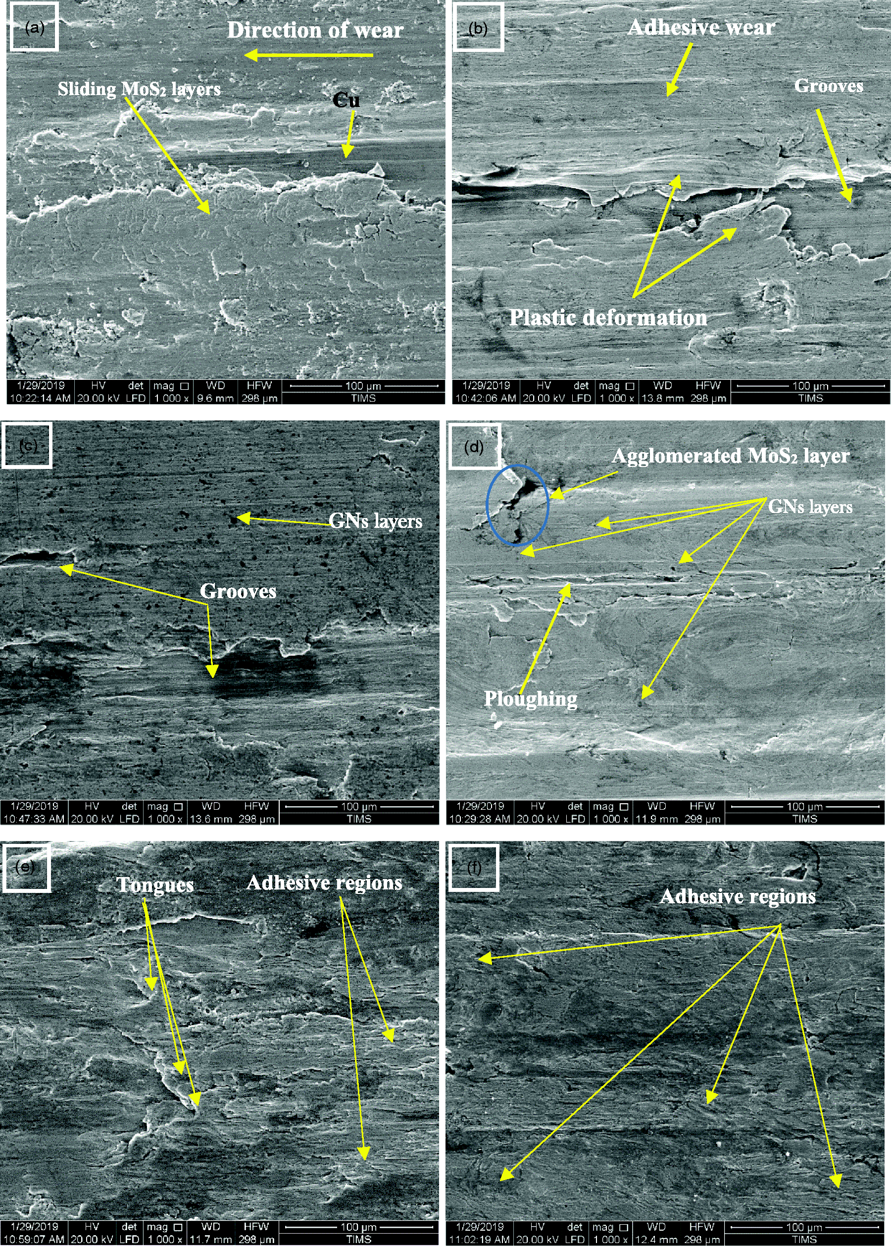
COF
The average of the COF of the (Cu-10MoS2) matrix and graphene reinforced (Cu-MoS2) nanocomposites at 20 N and 30 N load and 300 r/min rotational speed for 10 min are shown in Figure 11. As the figure shows, the COF is increased by increasing the applied load. The results show that the COF of the (Cu-MoS2) matrix is 0.41, and by reinforcing it with GNs, the COF is dramatically decreased and reaching to 0.22 at 0.4 wt.% GNs then the value of COF got increased again by increasing the GNs percentages. Regardless of increasing the COF at percentages over 0.4 wt.%, it is still better than that of Cu-10MoS2 matrix. The results at the same conditions and load 20 N show that the COF is reduced to 0.17 at 0.4 wt.% GNs, which is the best result at this load. The decrease in the COF that occurs due to increasing the GNs up to 0.4 wt.% may be attributed to increasing the strength of the composites and the reduction of the number of sliding layers, where the GNs is a single-layer material. The decomposition of graphite to graphene nanosheets
31
makes it lose its lubricity. The presence of GNs in a matrix in a homogenous distribution manner leads to increase the strength and hardness,19,32 which makes the resistance of matrix to the abrasion increasing and the relative motion becoming smooth, consequently decreasing the COF.
Coefficient of friction of the (Cu-MoS2)/ × GNs nanocomposites. GNs: graphene nanosheets.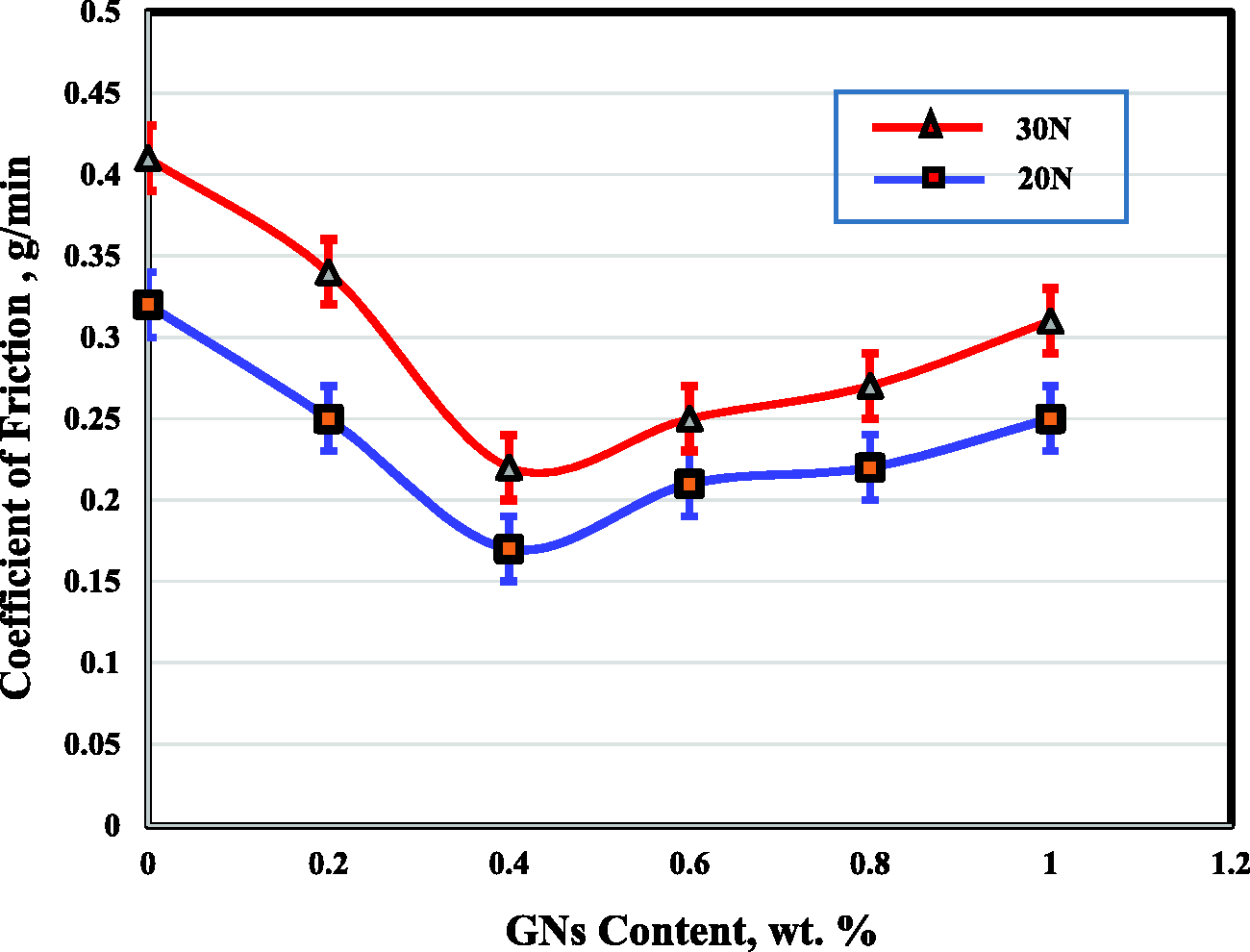
As the GNs wt.% increases over 0.4 wt.%, a turbulent in the composite takes place and encourages the probability of producing GNP that creates adhesive regions and subsequently increases the COF. Figure 10 of the wear mechanism illustrates that the adhesive marks and slid layers are reduced due to reinforcing the Cu-10MoS2 matrix with GNs and increase to 0.8 and 1 wt.% GNs samples.
The effect of the GNP on the COF of the copper matrix was investigated, and the results show that the addition of the GNP to the copper matrix reduces the COF of pure Cu from 0.6 to 0.25 at 4.0 vol.%. 30 The same results of the reduction in the COF have been achieved at load 20 N and 0.05 m/s, where the COF was reduced from 0.55 to 0.25. 33
Conclusion
The (Cu-10MoS2) nanocomposite matrix is prepared by the powder metallurgy technique. Five samples containing 0.0, 0.2, 0.4, 0.6, 0.8, and 1 wt.% GNs have been prepared. The high heating rate leads to produce swelling as a result of restraining gases inside the samples, while the low heating rate improves the sample densification.
The microstructure refers to the good adhesion and the good distribution of the MoS2 and the GNPs in the copper matrix. New copper–molybdenum sulfide (CuMo2S3) intermetallic is formed between the Cu and MoS2, as a result of the reaction between the Cu and MoS2. The hardness gets improved by reinforcing the matrix with the GNs up to 0.4 wt.%. The wear and the COF are enhanced by increasing the GNs up to 0.4 wt.%. The COF has been reduced from 0.41 to 0.22 at 30 N load.
Footnotes
Acknowledgements
The authors would like to thank technicians at the Faculty of Industrial Education, Helwan University and Central Metallurgical R&D Institute (CMRDI) in Helwan, Cairo, Egypt, for their cooperation.
Declaration of Conflicting Interests
The author(s) declared no potential conflicts of interest with respect to the research, authorship, and/or publication of this article.
Funding
The author(s) received no financial support for the research, authorship, and/or publication of this article.