
Abstract
The use of nanomaterials is gradually increasing with the progress of nanotechnology. In particular, the production of nanocomposites incorporating nanoparticles is one of the most significant areas in which nanomaterials are being used increasingly. The first objective of this research was to detect the punch shear or penetration resistance behavior and damage mechanisms of hybrid nanocomposites obtained by using silica (SiO2) nanoparticles. For that purpose, six different SiO2 hybrid nanocomposites with different laminations three layer (3La), 5La, 7La, 11La, 15La and 21La and different thicknesses (HC) of 0.95∼4.98 mm, were made by using vacuum assisted transfer molding (VARTM). During this research, quasi-static punch-shear (QS-PS) tests at span punch ratios (SPRs) of 1.16, 1.33, 1.67, 2.00, 2.33, 2.67, and more were conducted to determine quasi-static penetration mechanics and penetration resistance behavior. Moreover, deflection, energy dissipation, damage area, stiffness, and peak force values were investigated through experimental results and scanning electronic microscope (SEM) images.
Keywords
Introduction
In last quarter century, the application of composite materials has increased considerably. In particular, with the use of nanoparticles in composite production, the composite material applications have increased throughout industry. These new materials, called nanocomposites, have become leading materials in almost every sector, from aerospace to the defense industry, because of their superior properties and characteristics. The nanocomposites generally consist of three phases; fibers, resin, and nanoparticles. Carbon, glass, aramid, or basalt fibers usually make up the fiber phase; thermoplastic or thermosetting resins the resin phase; and fullerenes, silica nanoparticles, carbon nanotube (CNT), or graphene the nanoparticle phase. With the increasing importance of these materials in recent years, it has become widespread practice to produce composites containing different fibers, resins, and nanoparticles. Within this context, producing nanocomposites with various nanoparticles and understanding the structural properties of these new materials have attracted the interest of many researchers. Especially, there have been many studies of the impact behaviors and damage mechanisms of composites by the use of various test methods. The quasi-static punch-shear test (QS-PST) methodology has become one of the most widely used test methods by researchers in recent years due to its simple application techniques.1–19 The quasi-static punch shear (QS-PS) or indentation experiments are used to activate damage mechanisms similar to impact and penetration, however without strain rate effects. Also the low rate allows for the detailed analysis on the load response. Gama and Gillespie are presented ballistic damage and penetration mechanics of thick-section composites. In order to correlate the ballistic penetration damage mechanisms with quasi-static penetration (QS-P), experiments are designed to maintain similar boundary conditions. It has been found that the ballistic damage mechanisms can be mimicked by conducting a series of quasi-static punch shear experiments at different support spans. A quasi-static punch shear test (QS-PST) methodology is developed to quantify and partition the penetration energy into elastic and absorbed energies as a function of penetration displacement and support span. Based on this QS-PST experimental methodology, a ‘Quasi-Static Penetration Model’ of ballistic penetration is developed to mimic different phases of ballistic penetration. 18
The QS-PST has been extended to a direct-impact punch shear test (DIPST), and Gama and Gillespie 13 have developed the QS-PST to associate the value of elastic and dissipated energy with the quantity of penetration or punch shear deformation and with various dimensions of the support rings. Additionally, glass fiber-epoxy composites, which are widely used, especially for impact performance and other properties, were extensively examined and researched in last years,5–15 and many original papers have been published. The main reason for investigating such a wide range of materials has been to understand their energy absorption and impact damage mechanisms and to know their characteristics. Important results have been reported in some of those studies, and the literature has been introduced.
Gillespie and Gama 18 have made headway QS-PST methodology to establish a connection with the value of elastic and dissipated energy with amount of penetration deformation and with various dimensions of the support rings. Their research was presented that the QS energy absorption capacity of epoxy composite materials was 69% of the total ballistic energy limits. Furthermore, Gama and Erkendirci20,21 notified the penetration behavior of composite materials by performed QS-PST method to glass fabric and Kevlar fabric/thermoplastic composites.
Again, a wide range of detailed researches is being conducted with composite materials. One area of those studies involves the addition of nanomaterials into the matrix. The idea of using nanomaterials as fillers to improve the mechanical and physical properties of a polymer matrix is currently being explored and examined by scientists. The specific surface areas of the nanometer-sized particles can reach 1000 m2/g. 22 Due to these high specific surface areas, the transfer of charge from the matrix to the nanoparticle is facilitated, and, consequently, the mechanical properties of the matrix are enhanced. 23
In addition to CNT and SiO2, nanoclay, metal, and metal oxide nanoparticles have been the most widely used materials in polymer nanocomposites in recent years. Thus, montmorillonites, nanoclays, have a wide use in polymers due to their surface sensitivity and high surface area. 24 Also, Erkendirci and Avcı25,26 reported information on the effect of nanoparticles on mechanical behavior and penetration resistance.
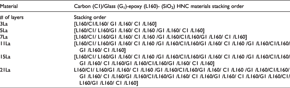
SiO2 nanocomposites were produced for this study by the use of vacuum-assisted resin transfer molding (VARTM) with glass and carbon fibers, and six different laminations (3La, 5La, 7La, 11La, 15La, and 21La) of SiO2 nanocomposites were made. In the production stage, to obtain homogeneous dispersion of SiO2 nanoparticles, the nanoparticles were added directly to the resin, and a mechanical blender was used for mixing. Hybrid composites were produced by using glass and carbon fibers together. In hybrid production, carbon and glass fibers are arranged in a particular order. For example, if a three-layer lamination is to be made, carbon is used in the upper and lower layers, and glass fiber is used in the middle layer. If a five-layer lamination is to be produced, carbon is used in the upper layer, and glass-carbon-glass-carbon, respectively, in the succeeding layers (Tables 1 and 2). In this research, QS-PS tests were performed at different span punch ratios (SPRs) ranging from 1.16 to 6.67 to determine quasi-static penetration mechanics and penetration resistance behaviors. The effects of QS-PST impact strength and energy absorption capacity on SiO2 hybrid nanocomposite (HNC) material laminates were researched.
Carbon-glass/epoxy (L160)-(SiO2) HNC materials stacking order.
Carbon/glass-epoxy (SiO2) HNC materials geometric properties and density.

Homogeneous dispersion of SiO2 nanoparticles in epoxy in the production stage is a very significant agent for developing epoxy resin mixture properties. The SiO2 was first added mechanically to the resin and later mixed to provide a homogeneous dispersion. After, the mixture was blended again with an ultrasonic miser for a while, and the fiber sheets were impregnated by means of VARTM. Next, the epoxy HNC sheets were subjected to QS-PS testing, and the dissipation energy and deformation values were researched and checked. Besides, the experimental results obtained and other data regarding the production and experiment stages are clarified in detail next sections.
Experiments
HNC material processing
Production of SiO2 HNC materials were used the vacuum-assisted reinforced transfer molding method (VARTM). Epoxy (type: MGS L160) (80% mixture ratio (mr)), hardener 1(type: MGS LH160) (4% mr), and hardener 2 (type: MGS LH260S) (16% mr) were used as epoxy resins for the production of the HNC material laminates. Plain-weave (PW) glass fiber (roving fabric, 300 g/m2) and PW carbon fiber (200 g/m2, 3k) were used as reinforcement material. In addition, silicon dioxide (SiO2) nanoparticles of 15–50 nm size (ρ 2.4 g/cm3, melting point 1600 °C, chemical composition 46.83% Si, 53.33% O2) were added to the epoxy resin in the weight ratio of 4% of that of the epoxy resin, and later the mixture was blended by mechanical and ultrasonic blenders sequentially. Stacking orders of the HNC composite laminates are given in Table 1. These laminates were produced in six different laminated panels (20 cm × 25 cm) as 3La, 5La, 7La, 11La, 15La, and 21La laminations. For example, the 15La HNC laminate can be seen in Figure 1.
Photo of 15La carbon-glass/epoxy-SiO2 HNC produced by the VARTM method.
The dimensions of thickness and mass were determined for computation of the areal density (AD) and density of the CNT/SiO2 HNC materials. Similarly, HNC materials density (ρ) and fiber volume fraction (Vf) for all layers were determined as stated by ASTM Standard 2584, and the areal densities of the laminates were found with the aid of the thickness and density of the HNC materials and is calculated by equation (1).

Where, in order, HC and ρC denote the average thickness and the average density of HNC materials. Carbon-glass/epoxy (SiO2) hybrid composite materials density and geometric properties are exhibited in Table 2.
Qs-PS tests
QS-PS test method is an advanced method for understanding damage mechanism energy absorption capacity and for finding the penetration resistance behavior in thick cross-section composites. QS-PS tests have several advantages over other impact tests, such as being more attainable and simpler to conduct, along with (conceivably more important) providing invariable and checked data acquisition from undamaged and damaged structures, which is inaccessible or unavailable with other impact tests.
In this method, tests are carried out by means of small and middle sized test fixtures, each consisting of a punch guide, a steel punch, a square bottom support plate and a top cover plate as shown in Figure 2. Both test fixtures consist of concentric rings that can be passed through each other and are interchangeable to produce punch diameters, various hole diameters, and span punch ratios (SPRs) (Figure 3). Diameter of support span (DS) can be varied from 7.7 mm to 101.6 mm. Punch head diameter (DP) is 7.63 mm, and the thickness of span is 25.4 mm. There are various support spans that yield various support span-to-punch diameter ratios (SPR = DS/DP). By different the test SPRs, one can test specimens for both shear and bending dominated loading. The smaller fixture was used for SPRs of 1.16, 1.33, 1.67, and 2.00, and the second, larger, middle fixture was used for SPRs of 2.33, 2.67, 3.00, 3.37, 5.00, and 6.67.
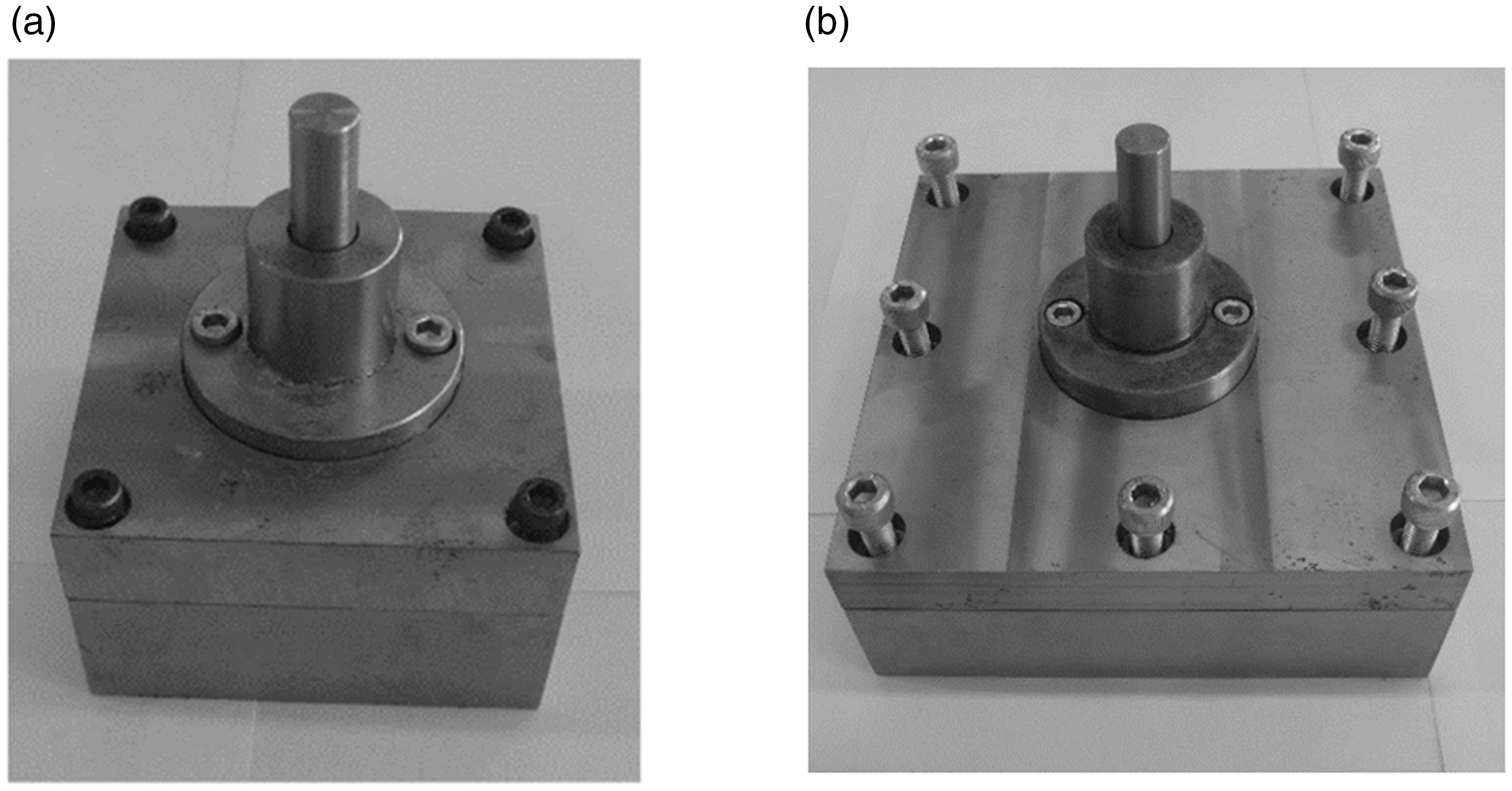
Small and middle fixtures for QS-PST snapshots. (a) Small test fixture; (b) Middle test fixture.
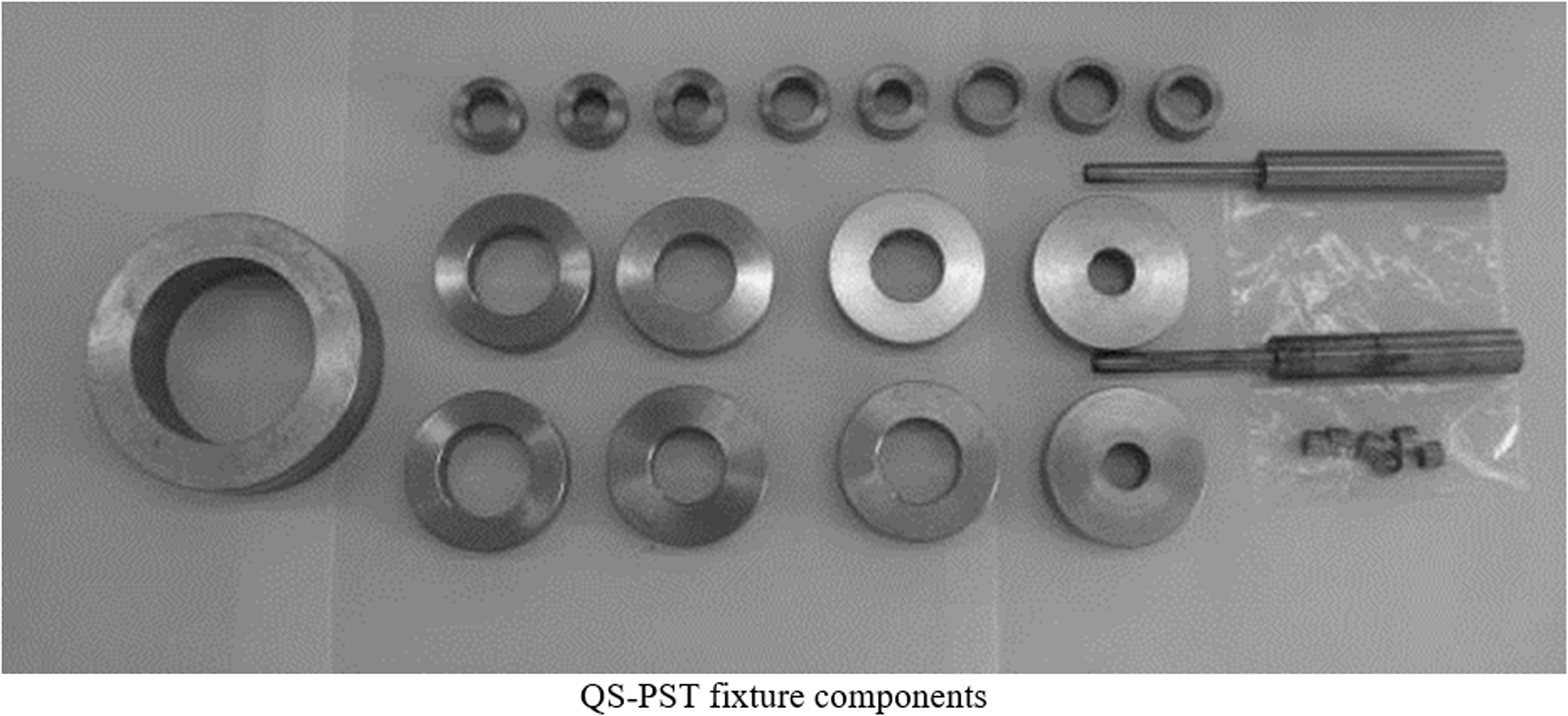
Photos of the concentric rings used for SPR, punch, and punch heads.
Quasi static punch shear (QS-PS) experiments were performed with 50 ton capacity Instron 8801 type universal test machine in the Selcuk University Engineering laboratory. In the experiments, displacement speed was controlled at 1 mm/minute.
During the QS-PS experiments, punch shear deformation used was a function of the penetration force, related to the HNC laminates thickness, and QS-PS test results were got for all HNC material layers. Afterwards, load versus displacement (L-D) data were compiled, and those data were computed individually as penetration resistance, dissipated energy amounts, and other parameters by calculation as functions of punch shear deformation.
Discussion and conclusions
QS-PS test results of SiO2 HNC materials are presented, because the penetration forces for various thicknesses were considered to be a punch displacement function in the QS-PS tests. Load-versus-Displacement (L-D) data were graphed first, later dissipated energy was determined like penetration stiffness, a function of punch displacement, and other parameters by further reducing the L-D data.
Penetration mechanics and penetration resistance behaviors
QS-PST tests were carried out on HNC laminates produced from 3, 5, 7, 11, 15, and 21 layers of carbon/glass PW fabric and at SPRs (DS/DP) of 1.16, 1.33, 1.67, 2.00, 2.33, 2.67, 3.00, 3.37, 5.0, and 6.67 to determine the resistance of SiO2 hybrid nanocomposites to penetration. If ‘n’ layers of fabric are used, the laminate is named as “nLa.”
Force-displacement (F-D) data and graphs
The data obtained for penetration resistance force plotted against displacement (F-D) for each laminate, at the same value ranges of force and displacement, for six thicknesses, 3La, 5La, 7La, 11La, 15La, and 21La, of SiO2 hybrid nanocomposite laminates (see Figure 4).
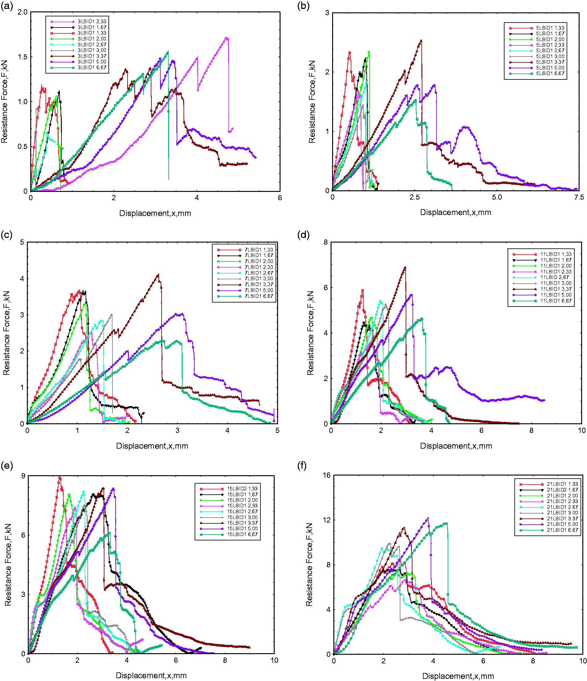
F-D graphs of carbon/glass-epoxy (SiO2) HNC laminates. (a) 3L carbon/glass SiO2 hybrid nanocomposite, (b) 5L carbon/glass SiO2 hybrid nanocomposite, (c) 7L carbon/glass SiO2 hybrid nanocomposite, (d) 11L carbon/glass SiO2 hybrid nanocomposite, (e) 15L carbon/glass SiO2 hybrid nanocomposite, (f) 21L carbon/glass SiO2 hybrid nanocomposite.
The work done throughout penetration process under quasi static loading, that is also the dissipated energy by the material (ED) in diverse damage mechanisms, is presented as the area under the F-D curve.

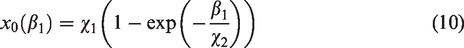
Wherein
These graphs show that there is commonly a linear segment of the curve up to the maximum force application, but some non-linearity is regarded in the force versus deformation behaviors. The curves also show that fracture or damage occur in the composite laminates when force is at maximum. This behavior is characteristic of HNC laminate systems. Besides, the penetration forces vary with the SPR ratios, which means that the damage and energy propagation are caused by pull-shear forces in the vicinity of the punch and that the maximum penetration forces tend to decrease for all thicknesses as a function of SPR.
Additionally, maximum resistance force and maximum resistance displacement graphs relative to the SPR ratios of SiO2 HNC laminates (3La, 5La, 7La, 11La, 15La, and 21La) after damage are given in Figure 5. As seen in these graphs, the highest, Fmax, force and the maximum final deformation amount of xF, as expected, were measured for the thickest panel, 21La, while the smallest values were measured in 3La, the thinnest laminate. Because force is strongly proportional to thickness, that was an expected outcome. Displacement should be similar for all layers, even if force is increased.

Contrast of Fmax at failure and XF at the end of penetration carbon/glass-epoxy (SiO2) HNC materials. (a) Fmax at failure, (b) XF at the end of the penetration
QS penetration damage mechanism analysis
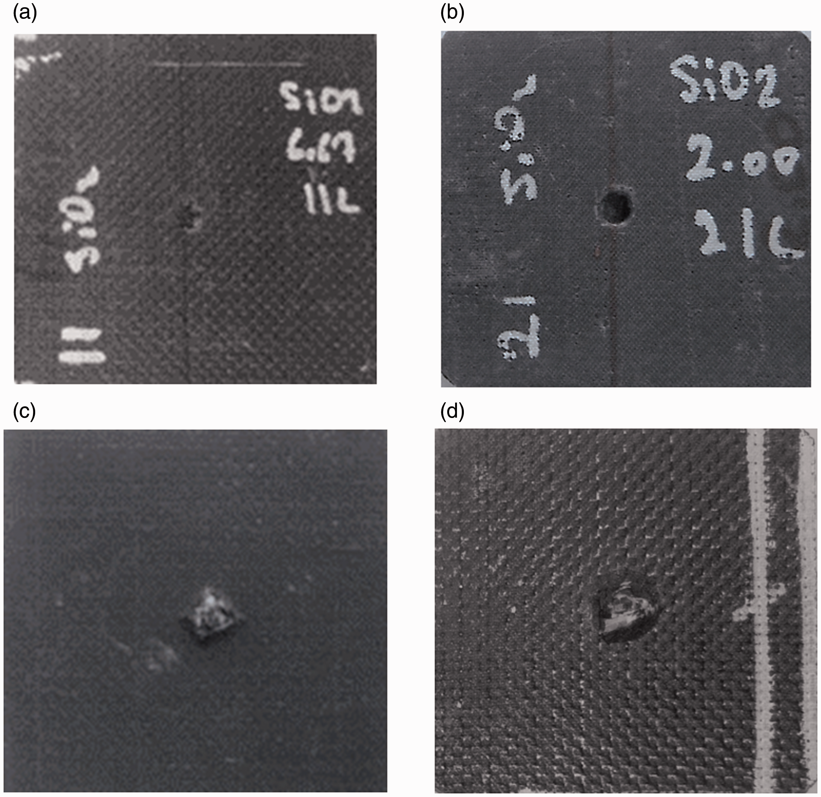
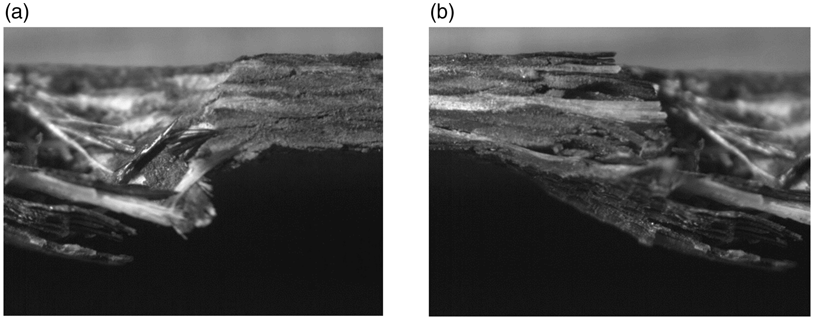
QS-PS testing was carried out at different support spans to study QS penetration behavior of carbon/glass epoxy composites. QS damage mechanisms varied as a function of support span ratio and HNC laminate thickness. The frontal and reverse photographs of the 11La and 21La samples after they were tested at SPR 6.67 and SPR 2.00, respectively, can be seen in Figure 6. Failure modes carbon/glass epoxy resin L160 (SiO2) HNC material systems include matrix cracks and brittle fiber fracture. SPRs of 1.16, 1.33, 1.67, 2.00, 2.33, 2.67, 3.00, 3.37, 5.00, and 6.67 were used to study nanocomposite laminates of different thicknesses in this study. Optical stereo photographs of the damage to the 11La sample at SPR 6.67 are presented in Figure 7. Regional or local punch shear and clean shear cutting of fibers are also observable. That is evidence of two penetration phases of membrane tension shear deformation of the complete laminate shielded by the support span, as well as regional tension shear influenced failure at the periphery of the punch. Figure 8 shows SEM images of fiber fracture and matrix cracks in the nanocomposite material.
Photographs of frontal and reverse surface punch shear damage behaviors of carbon/glass-epoxy (SiO2) HNC materials, 11La at SPR 6.67 and 21La at SPR 6.67, (a) frontal surface, (b) reverse surface.
Damage of carbon/glass epoxy (SiO2) HNC materials 100 times magnified stereo microscope snapshots, 11La at SPR 6.67.
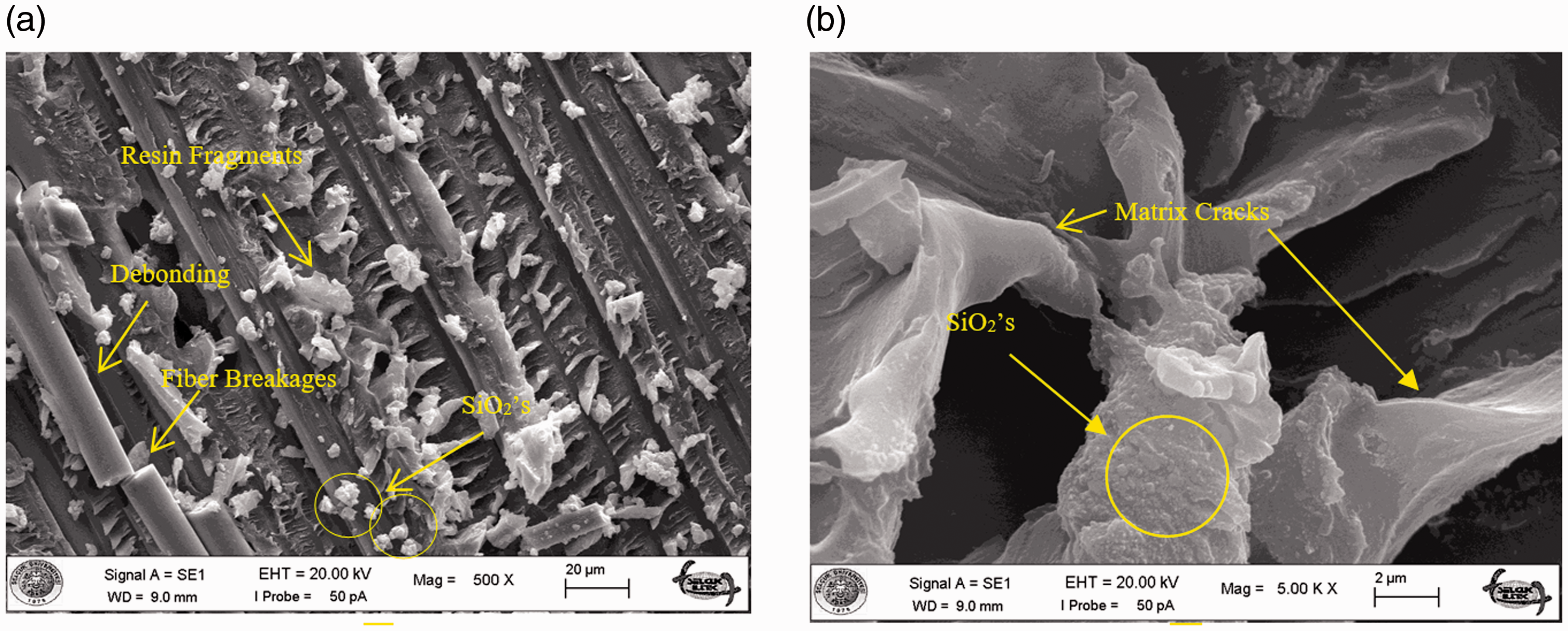
SEM images fractured surface of carbon/glass-epoxy (SiO2) HNC materials.
Dissipated energy under QS loading
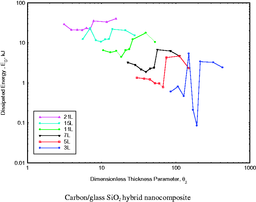
The amount of dissipated energy (ED) of hybrid nanocomposites under QS loading is obtained by using equation (2), and θ2 is a function of the dimensionless inverse thickness parameter as per Ayote and others.
27
Values of ED for SiO2 HNC materials are presented in Figure 9. Dissipated energy amounts for varying material thicknesses were obtained from log-log plots and separated into groups that show us that these data are also a function of thickness of hybrid nanocomposite material laminates.


QS energy dissipation as a function of
The dissipated energy for HNC material can also be expressed as a function of areal density, AD (determined by equation (1)), for each of the specific SPRs (Figure 10). Carbon/glass SiO2 hybrid laminates show minimal deformation behavior, so the QS dissipated energy was found to be generally higher for all SPRs until a limiting areal density/thickness of the laminate was reached.
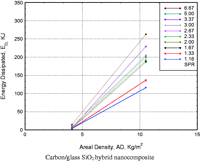
QS energy dissipation as a function of areal density.
Average penetration resistance behavior and nonlinear penetration stiffness
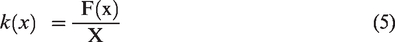
QS approach of the capability of the materials to dissipate energy under penetration behavior and ballistic impact could not be anticipated, because the carbon/glass SiO2 hybrid nanocomposite material systems did not exhibit such a “QS envelope” behavior. A new description of “nonlinear penetration stiffness” (NL-PS) was coined20,21 to express an average penetration resistance behavior for this group of composite materials. If the force exerted by QS-PST loading to produce penetration displacement, x, is expressed as F(x), the following equation can be used to define NL-PS:
Next, the penetration resistance force can be named as:

The NL-PS for all HNC laminate thicknesses, 3La, 5La, 7La, 11La, 15La, and 21La, is shown in Figure 11. The curve was generated by using equation (5) to transform Figure 4. Note that none of the force-versus-displacement plots in Figure 4 shows any penetration resistance behavior that is self-similar. However, a degree of self-similar penetration resistance behavior is shown in Figure 11 and is delineated by a single “envelope” curve representing the locus of all the k (x) ∼ x curves at various SPRs for each HNC material thickness. Such a plot predicts the behavior of the material at a specific thickness within the “nonlinear penetration stiffness envelope” (NL-PRE). It can be expressed in the form of

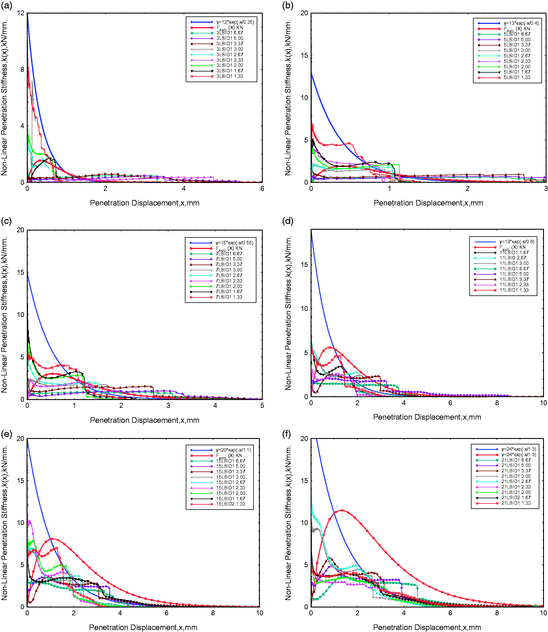
Nonlinear penetration stiffness behavior (NL-PS) of carbon/glass epoxy (SiO2) HNC systems. (a) 3La carbon/glass SiO2 hybrid nanocomposite, (b) 5La carbon/glass SiO2 hybrid nanocomposite, (c) 7La carbon/glass SiO2 hybrid nanocomposite, (d) 11La carbon/glass SiO2 hybrid nanocomposite, (e) 15La carbon/glass SiO2 hybrid nanocomposite, (f) 21La carbon/glass SiO2 hybrid nanocomposite.
Figure 12 shows nonlinear penetration resistance envelope (NL-PRE) plots for HNC laminate thicknesses (see the inscription for k(x)). The average penetration resistance force (APRF) plot can be determined by using equation (6) to transform equation (7). APRF has the functional form of

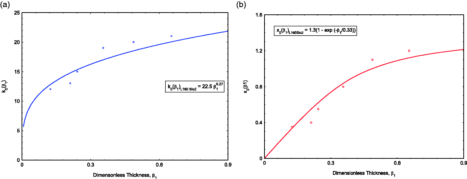
Parameters of nonlinear penetration stiffness envelope (NL-PRE) plots. (a) Parameter k0 (β1), (b) Parameter x0 (β1).
The parameters 
APRF, which is denoted to evaluate the average penetration resistance of each HNC laminate, is determined by equation (8) and is considered to be the baseline. It is presented in Figure 13(a) and in Figure 4. Figure 13(b) additionally shows the energy dissipation values calculated by integrating those plots.
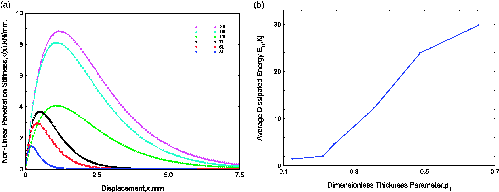
APRF and energy dissipation values of carbon/glass epoxy (SiO2) HNC material for all layers. (a) Carbon/glass SiO2 hybrid nanocomposite, (b) Dissipated energy from APRF curve.
Summary
Punch shear penetration resistance behaviors of carbon-glass/epoxy resin L160 (SiO2) HNC materials with varying thicknesses (HC), from 0.95 mm to 4.98 mm, were studied under quasi-static loading for this paper. QS-PS experiments were carried out at a set of diameter of support to diameter of span punch ratios (SPRs), which revealed many details about the damage mechanisms and enabled measurement of the energy dissipation capacities of carbon-glass/epoxy resin L160 (SiO2) HNC material systems. Initial damage to the composite material could be detected and was known due to the inelastic behavior of epoxy resin. Similarly, hybrid nanocomposite material laminates have potential for efficacious and full dissipated energy, more energy dissipation in the event of thinner HNC material laminates and less energy dissipation for thicker HNC material laminates. These behaviors of carbon-glass/epoxy SiO2 HNC laminates promise that HNC materials will be constructive in impact and/or penetration applications.
Footnotes
Declaration of Conflicting Interests
The author(s) declared no potential conflicts of interest with respect to the research, authorship, and/or publication of this article.
Funding
The author(s) disclosed receipt of the following financial support for the research, authorship, and/or publication of this article: This project (project number: 213M631) was supported by TUBITAK.