
Abstract
Fibre metal laminates (FML) are being used in automotive, aerospace and naval applications due to their light weight and superior performance. The FMLs are made by sandwiching composite with metal. The environmental concerns due to non-biodegradability of such structures, lead to the development of FML containing natural fibre composites. Natural fibres composite, despite having good damping properties have overall poor mechanical properties. However, this aspect can be improved by weaving the fibres in 3 D pattern. In literature, FML made using 3 D woven jute composites is never reported. Furthermore, no literature is found on adhesion of natural fibre composite-metal bonding. In this paper, development of novel 3 D Jute Reinforced natural fibre Aluminium Laminates (JuRALs) is reported. Furthermore, the effect of 3 D weaving pattern and metal-composite bonding on mechanical properties and failure mechanism of the developed samples is also discussed in detail. The four-layered 3 D woven Jute fabric reinforcement was made using four interlocking patterns. The composites and JuRALs were fabricated using epoxy resin by vacuum infusion technique. The surface of aluminium was treated using phosphoric acid anodizing. Tensile, flexural and T-peel tests were performed according to ASTM testing method using Z100 All-round, Zwick Roell. The results showed that out of four types of used reinforcements, the through-thickness composites had better tensile properties while layer-to-layer composite had better flexural properties. The tensile and flexural properties of JuRALs made with through-thickness interlock reinforcement were better as compared to layer-to-layer interlock reinforcement. The T-peel results depicted that the constituent materials influenced the metal-composite adhesion properties, rather the type of 3 D structure.
Introduction
For the past decades, aluminium alloys and Fibre–Reinforced Composites FRCs are widely used in the manufacturing of aircraft components. These materials have several advantages, such as light weightiness and excellent mechanical properties. 1 To combine the best physical and mechanical properties of aluminium and FRCs, a new hybrid material was developed called Fibre Metal Laminate FML.2–4 Different types of metallic alloys can be used to manufacture the FMLs, e.g. aluminium, magnesium and titanium. Note that FMLs are often made from thin aluminium alloy sheets. Due to excellent mechanical properties, fibre metal laminates can be used in aerospace, marine, ballistic and automotive applications. 5
Generally, the FRCs are made using synthetic fibres such as glass, carbon and aramid fibres. So, among the most widely used families of FMLs are GLAss REinforced aluminium laminates GLARE, CArbon Reinforced Aluminium Laminate CARAL and Aramid-Reinforced ALuminium Laminate ARALL.6–8
In the literature, several pieces of research have been reported on the manufacturing process and mechanical properties of FMLs containing thermosetting and thermoplastic resins. In addition, different reinforcements and surface treatments of metal sheets are applied to improve the properties of FMLs and to explore other applications. 2
Often, properties of FMLs are defined by Metal Volume Fraction MVF, that is the ratio of the thickness of all metal layers and the total thickness of laminate as shown in the below equation:
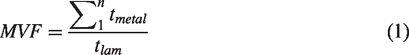
In equation (1),
Precisely, MVF value describes the contribution of the metal layer in FML; it varies between 0 and 1. MVF 1 means monolithic aluminium, while MVF 0 indicates contribution only of fibre layer. It is important to note that MVF plays a significant role in the final mechanical properties of FMLs. 9 In a characterization study of FMLs, WU et al. 10 used MVF approach to predict the tensile and flexural properties of fibre metal laminates. The predicted results showed a good increment with the experimental data.
Recently, several experimental and numerical studies have been carried out to determine the mechanical properties of FMLs, which were subjected to tensile, flexural, shear, fatigue and impact loading.11–13 Moussavi Torshizi et al. 14 conducted a study to check the effect of different combinations of Uni-Directional UD Glass/Kevlar reinforcement at 0°, 45° and 90° orientations on tensile properties of FMLs made with epoxy matrix. The results showed that FMLs made with the 0° orientation of reinforcement had superior tensile properties than other FMLs. In order to increase the adhesion of metal and composites in FMLs, different kinds of surface treatments on metals are used, Lee Hamill and Steven Nutt 15 compared the adhesion properties of FMLs made with aluminium 6061–T6 and Bulk Metallic Glass BMG alloys. They performed a lap shear test for three different types of metal surface treatments such as abrasion, Phosphoric Acid Anodization PAA, and silane treatment. The results showed that aluminium had better properties with PAA when compared to BMG alloy. The improvement of the metal composite interface is a major challenge in FMLs. Qaiser et al. 16 used PAA to increase the surface roughness of aluminium 2024–T3 in order to improve the adhesion with composite. They compared their results with non–anodized aluminium FMLs for T–peel test. The results showed that anodized aluminium FMLs have higher adhesion properties.
Although many articles have been published on the mechanical properties of FMLs, as evidenced by several reviews in the literature,17–19 research on enhancement of their performance needs to be further extended on manufacturing techniques, experimental tests and numerical modelling.
In recent years, the development of new ranges of green composites based on natural fibres such as flax, jute, kenaf, coconut and sisal is a response to the requirements of a sustainable environment. 20 In several industrial applications, natural fibres are already being used as a reinforcement for composites manufacturing. 21 It has been noted that several researchers are developing new FMLs based on natural fibres called Natural Fibre Metal Laminates NFMLs.22–24 NFMLs can be distinguished in two types, (i) with a reinforcement of natural fibres only and (ii) with a hybrid reinforcement in which a combination of natural fibres and synthetic fibres is being used. 25 Recently Mohammed et al. 26 have developed natural hybrid fibre–metal laminates with a combination of carbon/kenaf and carbon/flax. The authors highlighted the best flexural properties of carbon/kenaf–based FML, while the carbon/flax combination produced excellent tensile and impact properties.
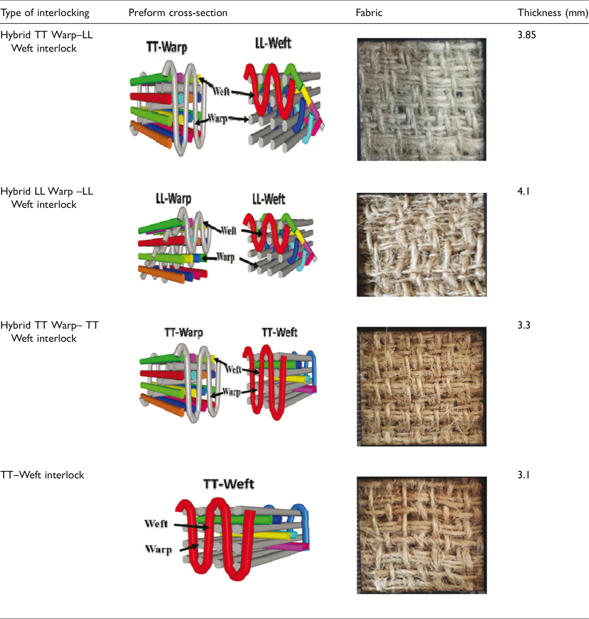
Although much research has been conducted on natural fibre-based FMLs in recent years, NFMLs are yet not used for technical applications. As the most of the work has focused on the determination of the mechanical properties of NFML using 1 D or 2 D reinforcement. 27 The use of 3 D woven natural fibre reinforcement in FMLs will not only increase its mechanical performance, but will also be a more economical solution when compared to other preforms. 28 The 3 D structures are broadly classified as orthogonal interlock structures and angle interlock structures. The interlocking can be further Through the Thickness TT or Layer to Layer LL. 29
From the above discussion, it can be concluded that the mechanical performance of simple composites can be enhanced by sandwiching them in thin aluminium plates. It should also be noted that 3 D reinforced woven composites have superior mechanical properties compared to composites reinforced with 2 D woven fabrics.
To our knowledge, no work in which 3 D woven design made from natural fibres have been used to manufacture FMLs and also the metal–composite adhesion properties of NFML have not been investigated. Therefore, in this study, new NFMLs are developed made with a 3 D woven fabric and to manufacture JuRALs, four different types of 3 D orthogonal interwoven fabrics were used as reinforcements. They were made with a combination of layer–to–layer and cross-ply interlocking. JuRALs and Jute Fibre Reinforced Composites JFRCs were manufactured using vacuum infusion technique. Tensile and flexural properties of JuRALs were investigated to analyse the effect of different types of reinforcements on mechanical properties and its failure mechanism. A comparative study between the four configurations with and without 7075–T6 aluminium sheets were made. Further, the T–peel tests were performed to verify the effect of surface treatment and to check the metal–composite delamination pattern. Finally, failure mechanisms were also analysed from microscopic observations.
Experimental procedure
In this section, the material and experimental procedure used to make JFRCs and JuRALs is being presented. The JuRAL used in this study consists of 2/1 lay-up, in which one 3 D Jute Woven Fabric JWF ply was sandwiched between two aluminium plates.
Materials
The 3 D woven fabric reinforcement was made with jute yarn and weaved on conventional shuttle terry–dobby loom. The 3 D woven fabric reinforcement had 4 layers each and layers were interlocked using four different types of interlocking patterns. All 3 D woven fabrics had square quality with
3D woven jute reinforcement’s structures, cross–sections and woven fabrics.
The aluminium 7075–T6 Alclad was used with a thickness of
Manufacturing process
The JFRCs and JuRALs used in this study were made using the materials mentioned earlier in the following sequence. For the fabrication of JFRCs and JuRALs all types of reinforcements were cut in the weft direction and subsequently the samples were also taken in the weft direction (length × width = weft × warp). The surface of aluminium was prepared both mechanically and electrochemically to enhance the adhesion between metal and composite. The mechanical preparation involved abrasion with sandpaper and electrochemical treatment was done by anodizing. In the current study, the PAA was used as it produces a more porous oxide layer, which leads to good adhesion between metal and composite. 16 , 30
Before doing any surface treatment, the surface of aluminium was cleaned with ethanol to remove dirt, dust and debris for better bonding, after cleaning with solvents the surface was rubbed with sandpaper of 800, 1000 and 1200 grades respectively. After a mechanical abrasion and subsequent cleaning, the aluminium was anodized. The anodizing process was carried out according to ASTM D3933 standard.
The JFRCs and JuRALs were made using vacuum infusion technique. The vacuum infusion process is a simple one-step process and can be used instead of the autoclave to manufacture FMLs. 31 All FMLs were made with a stacking sequence of 2/1. The single 3 D jute fabric layer was placed in between two aluminium plates, as shown in Figure 1.
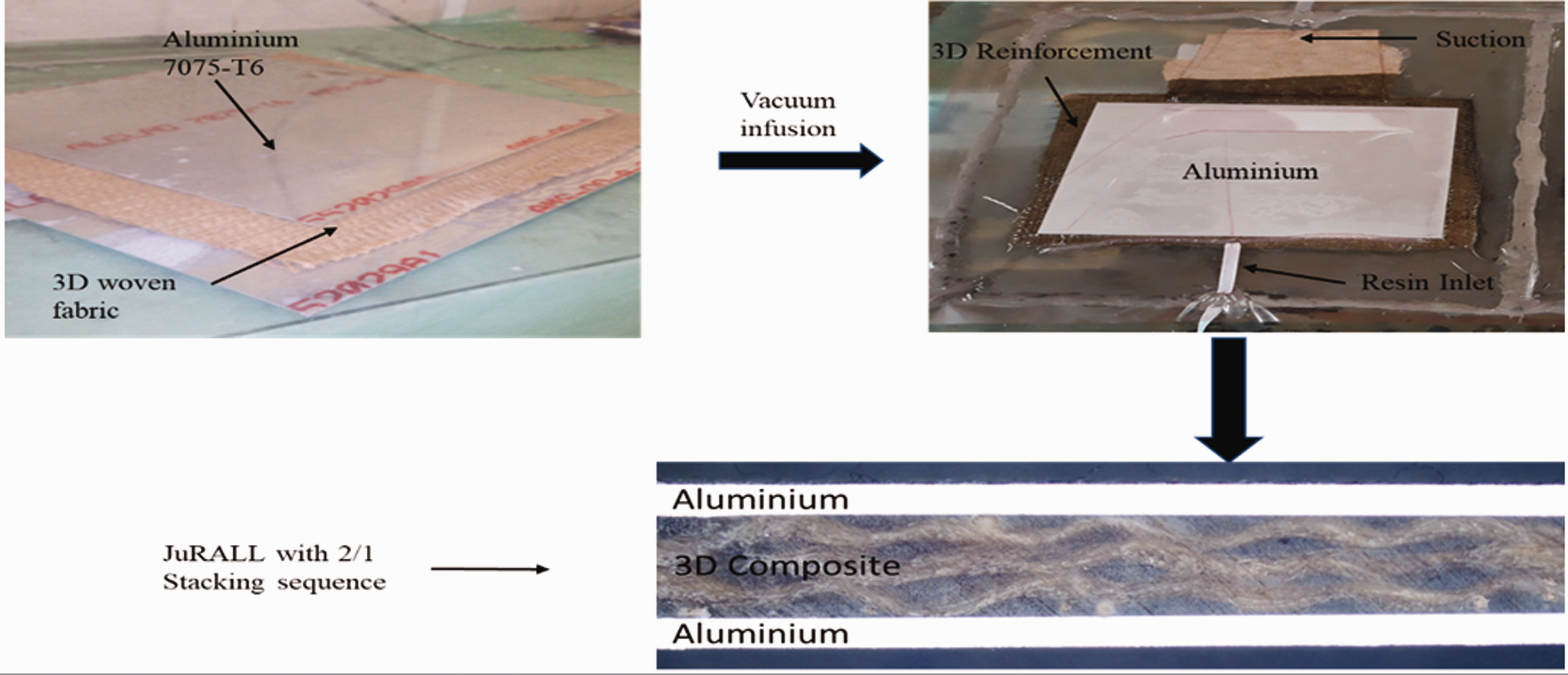
JuRAL fabrication process using vacuum infusion.
The details of JFRCs and JuRALs notations and corresponding thicknesses are shown in Table 2.
JFRCs and JuRALs samples detail with sample notations.
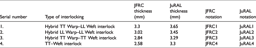
The fibre volume fraction of JFRC and JuRALs was in the range of 0.29 ± 0.1. The thickness of different type of JuRALs was different depending upon the thickness of reinforcement used. The MVF of JuRAL1, JuRAL2, JuRAL3 and JuRAL4 was 0.33, 0.35, 0.36 and 0.36 respectively.
Mechanical testing
The T–peel test was used to check the bonding strength between the metal and composite. The tensile and flexural tests of JuRALs and its constituents were carried at a quasi-static rate of loading to study the effect of change in properties from JFRCs to JuRALs. All the samples were cut using a band saw cutter.
The T–peel test was performed according to ASTM D1876 standard at a crosshead speed of
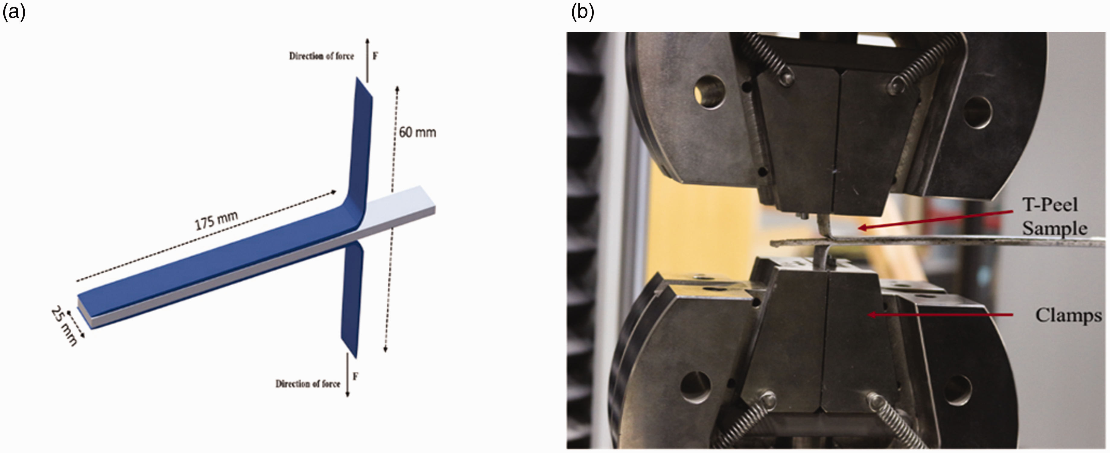
(a) Schematic view of the specimen for T–Peel test (b) T–Peel sample mounted on the machine.
The 3 D woven jute reinforcement was tested according to ASTM D5035 standard. The tensile test for JFRCs and JuRALs was carried out using the ASTM D3039 standard at a crosshead speed of
Results and discussion
T–Peel test
The T–peel test results of JuRALs are very important to understand the delamination behaviour of metal–composite bonding in NFML. As most of the natural fibre reinforcement is made using spun yarn, so the behaviour of delamination will depend heavily on the properties of the material used to make reinforcement. Figure 3 shows the typical load extension curve of T–Peel test of JuRALs.
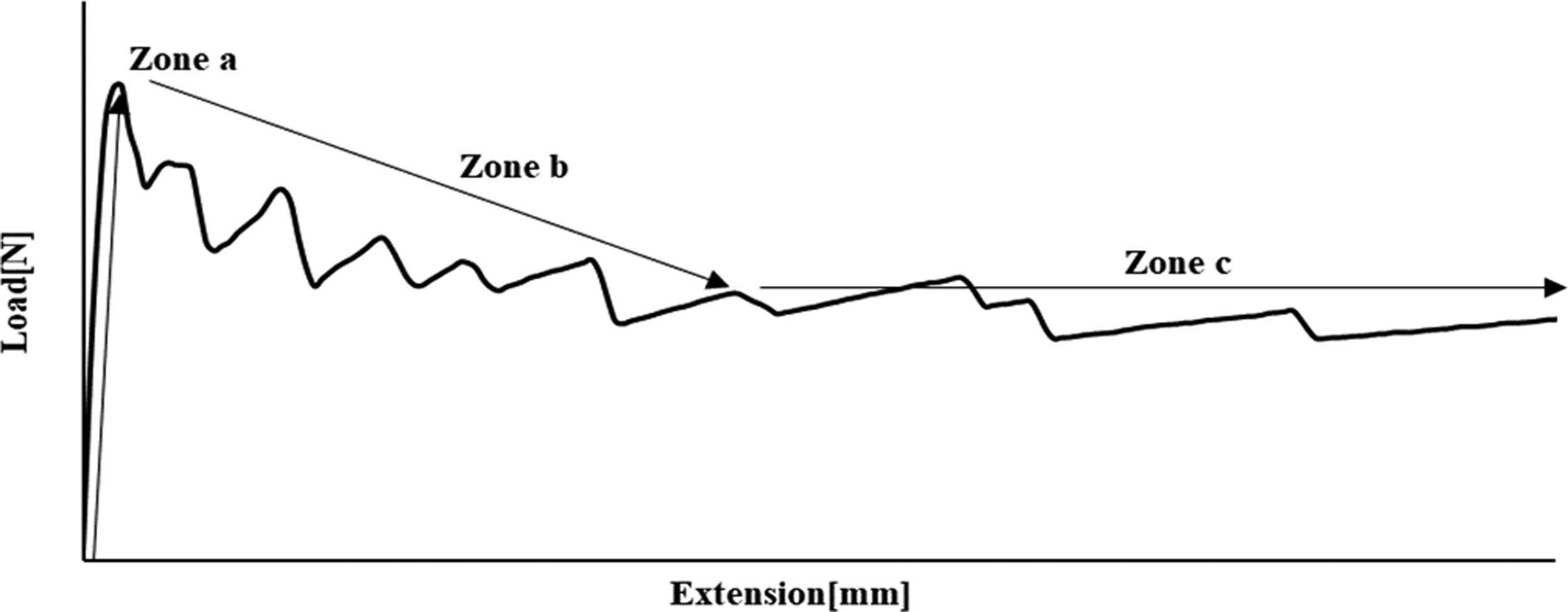
Typical load–extension curve of T–Peel test of JuRALs.
The curve shows the nature and delamination pattern of JuRAL made with 3 D jute woven reinforcement, epoxy and aluminium. The T–Peel test curve for JuRAL can be divided into three principal zones; (a) in the first zone, the applied load increases rapidly until reaching its maximum value with very small delamination. In this zone commonly the crack initiation occurs; (b) in the second zone the softening starts due to decrease in fibre bridging, that is why the value of load start dropping; (c) in the third zone the curve follows the stable pattern until complete delamination. This kind of behaviour of the load–extension curve is also reported in previous works. 16 The reason for this kind of curve is that the crack initiation required the highest amount of force, as that higher force is used for matrix cracking to make way for crack. The matrix crack in case of T–peel test is in the adhesive layer joining aluminium and composites. After the crack initiation, the force decreases because once a crack has been initiated; it will only be propagated with a constant force. The trend of the curve also indicates the brittle behaviour of the epoxy matrix; that is why there are sharp slopes in the curve. Figure 4 shows the average load–extension curves of JuRALs T–Peel test.
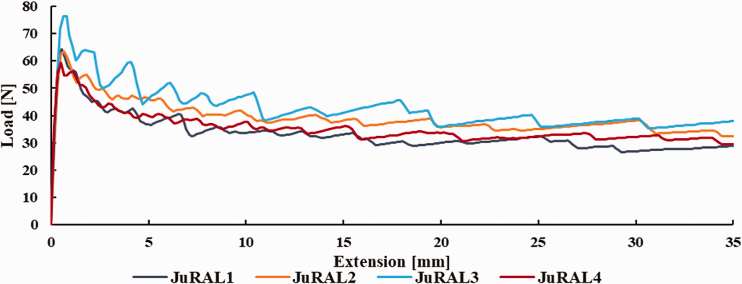
The average load–extension curves of T–Peel test of JuRALs.
The results of the T–peel test shows that the delamination properties of all types of JuRALs were in a similar range and there was not much difference in the average values of the load. There was no sudden drop observed in the curve showing the even adhesion. The failure during delamination was either cohesive or adhesive. The adhesive failure is a type of failure between adhesive and adherend, such kind of failure occur if bonding of the matrix is not very good with aluminium or composite and cohesive failure is in the matrix layer. The cohesive failure is an indicator of excellent adhesion of matrix with metal and composite. 32 The interlaminar failure was not seen as the reinforcement was 3 D woven (Figure 5).
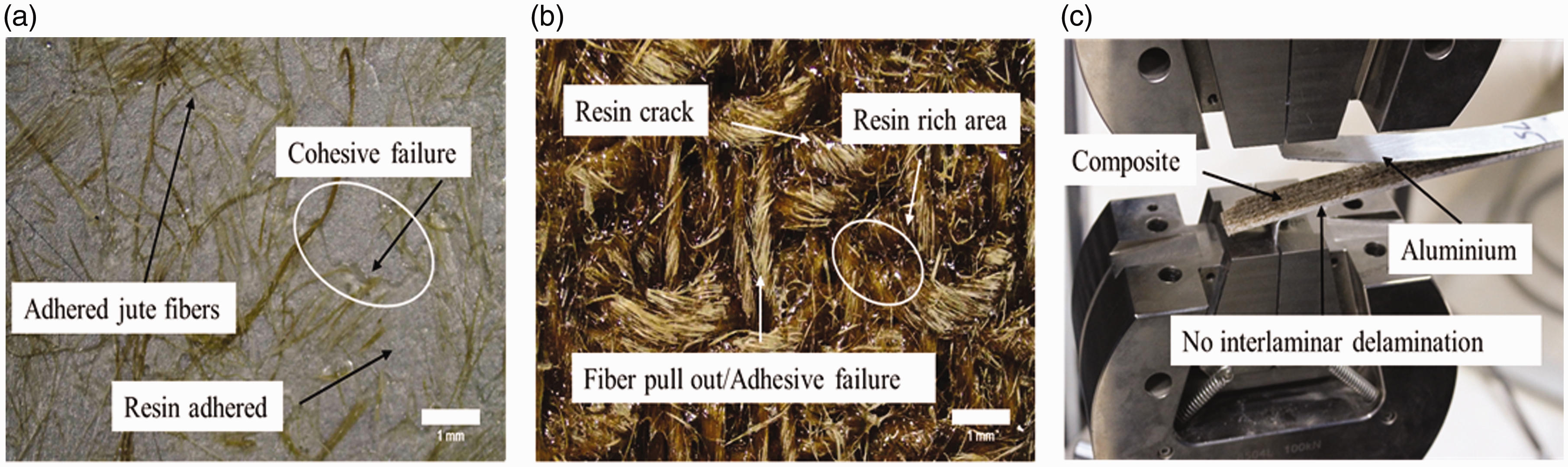
Microscopic images of the delaminated surface of (a) aluminium (b) composites (c) delamination phenomenon of JuRAL.
The graph also indicates that the delamination pattern of all the JuRALs was almost the same; the reason for that similar behaviour was the nature of the material used to make JuRALs which was epoxy, aluminium and jute. The delamination properties were determined by the adhesion between jute, aluminium and epoxy as the material was not changed, so the trend was also almost similar. The graph also indicates clearly that there was no clear correlation between delamination properties and different structure type of reinforcement of JuRALs. Despite the same material, there was a difference in values of the peak as well as the average load for different JuRALs. The reasons for this difference are;
As the delamination properties are only concerned with the contacting part of the materials being used, so this behaviour of JuRALs is understandable. As the samples were prepared using the Vacuum Infusion VI technique, so there can be a slight variation of the adhesive layer from sample to sample. As in VI resin is infused by vacuum, unlike autoclave where prepregs are used.
The fracture toughness 
In equation (2), A is the fracture energy, area under the curve
Table 3 shows the maximum and average values of peel force recorded during the T–peel test and also corresponding fracture toughness.
T–Peel force and fracture toughness properties of JuRALs.
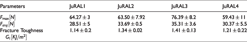
The average force of all the JuRALs is in the same range, the average force is very important parameter to determine the peel strength.
Figure 5 shows the microscopic images of aluminium and composite surfaces after delamination. It can be seen clearly that the resin and jute fibres have adhered to the surface of the aluminium. When analysed the composite surface, it confirmed that at some points there were fibre pull-out and cohesive failure. Some spots showing that there were cracks in the cohesive layer of resin, especially the resin rich areas. The reason of the resin rich and resin poor areas was due to weaving of 3 D reinforcement, there was slight uneven at the top of the fabric due to interlocking of yarn. It is also visible from the surface of aluminium and composite that the delamination was mostly on the side of composite rather on aluminium. The porous oxide layer on the surface of aluminium offered very good interlocking sites to resin as compared to jute fabric. As the reinforcement was made with low modulus jute yarn so the effect of fibre bridging was not as prominent as it should be in case of synthetic fibres. Therefore, the complete cohesive failure cannot be observed for reinforcements made with natural fibre.
Tensile test
JuRAL is made of aluminium and JFRC so offer very distinct tensile properties than its constituents. Figure 6 shows the typical stress-strain curve for JuRALs.
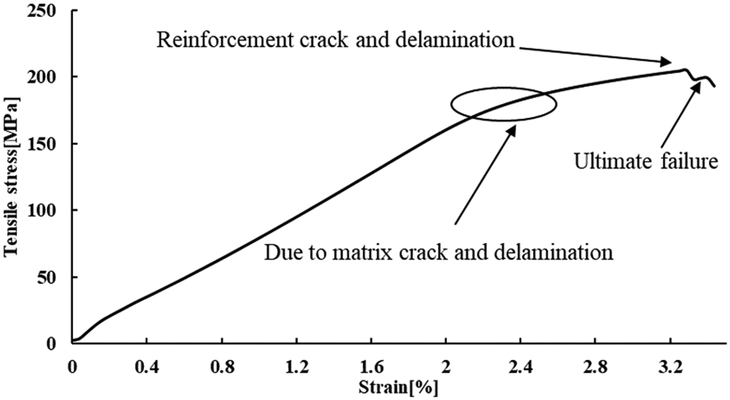
Typical tensile stress-strain curve of JuRAL.
The curve shows that at the start, both stress and strain increase proportionally until the start of the matrix crack around 2.2% strain, once start cracking, the crack keep propagating. Then at the end of the curve, there are two slopes one at higher stress and other at lower stress values. The reason of high tensile fracture strain is that the JuRAL is composed of aluminium and JFRC, as a tensile fracture strain of aluminium is higher than composite layer so damage initiate from composite layer and then propagate to aluminium layer. 33 In JuRAL addition of aluminium metal above and below the JFRC has given both extensibility and load-bearing ability which is not possible alone with composites.
Out of two slopes at the end of the curve, one slope at maximum load and other which is relatively at lower force correspond to failure. After reaching at maximum load the curve shows a steep decrease caused by the interface debonding of the laminate due to matrix cracking. Subsequently, the applied load increased at a relatively smaller slope compared with the former until ultimate failure, where the complete failure occurs. 34 There is a net increase in tensile strength of JuRAL due to two reasons; first addition of metal above and below the JFRC and the second reason was that the surface of aluminium was chemically prepared which increased bonding significantly. 35 In JFRC only fibres and epoxy determines the mechanical properties, while in JuRAL metal also played a crucial role in properties along with fibre and epoxy. 8
Figure 7 show the typical load-displacement curve of static tensile test for JFRCs and JuRALs.
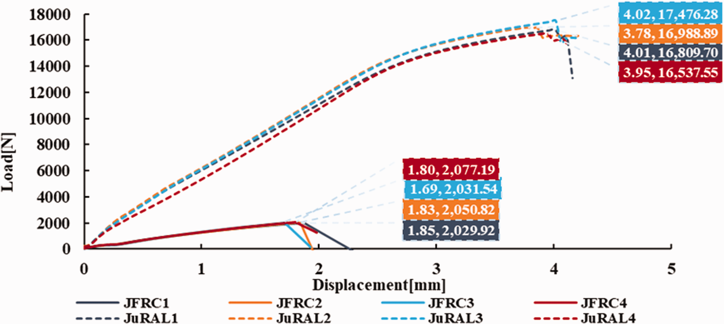
Tensile load-displacement curves of JFRCs and JuRALs for tensile test.
The graph shows that how properties changed from JFRCs to JuRALs. The tensile properties of JFRCs were less than respective JuRALs due to the obvious reason of the effect of aluminium.
Figure 8 shows the comparison of average stress-strain curves of static tensile test of JFRCs, JuRALs and aluminium.
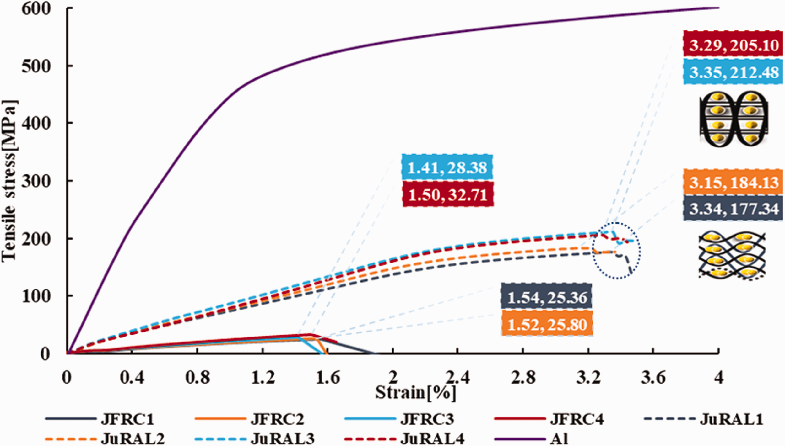
The average tensile stress-strain curves of JFRCs, JuRALs and aluminium.
The JFRCs and JuRALs reinforced with TT–interlocked fabrics, both have high tensile strength. This increase in composites had been due to already described reason while in JuRALs there was another factor which had contributed to the tensile properties was MVF. The higher the MVF more dominant will be the effect of the metal. That’s why higher tensile strength was achieved for JuRAL3 and JuRAL4 than JuRAL1 and JuRAL2, due to the coupled effect of MVF and interlocking pattern of the jute reinforcement. The tensile fracture strain is almost double for JuRALs as compared to JFRCs; the reason for this high fracture strain is already described. JFRC break with a sharp steep curve, unlike JuRAL due to brittle nature of thermoset resin and absence of aluminium. In JuRALs before ultimate breakage the specimen experience different mechanism, the failure starts with matrix cracking which leads to delamination between aluminium and composite. Once the delamination starts, the FMLs crack more quickly. Table 4 shows the tensile properties of JuRALs and its constituents.
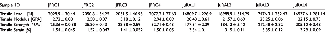
Tensile properties of JFRCs and JuRALs.
The dominant failure mechanism observed in JuRAL was delamination, matrix crack, metal crack and fibre failure unlike JFRC in which only matrix crack and fibre failure, as shown in Figure 9.
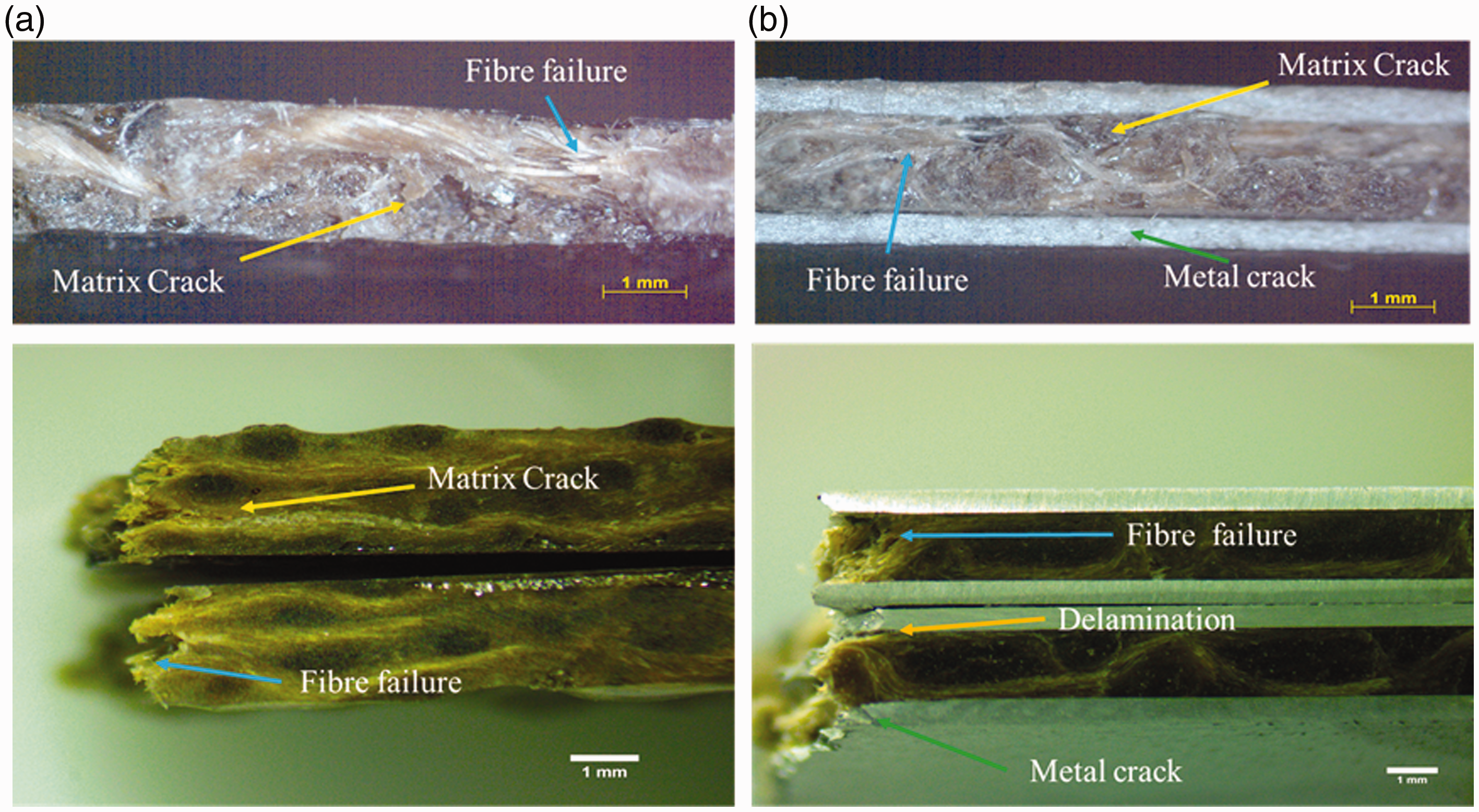
Microscopic images of (a) JFRC and (b) JuRAL showing side and fracture face after the tensile test.
It shows that there was a slight debonding between the metal and composite layer. This debonding before complete failure caused two slopes at the failure point in the curve as can be seen in Figure 6. There is another factor which contributes towards such type of failure is the low modulus and low stiffness of jute fibres, the fibre bridging is not very obvious with jute reinforcement in JuRALs, so the sharp crack was observed. The crack passes sharply through the sample thickness without spreading. As the significant contribution against loading was from aluminium metal, and the pattern of failure also justifies such behavior. 36
Flexural test
The flexural properties of JFRCs and JuRALs were obtained using the already described procedure. Figure 10 shows the typical stress-strain curve of the flexural test of JuRAL.
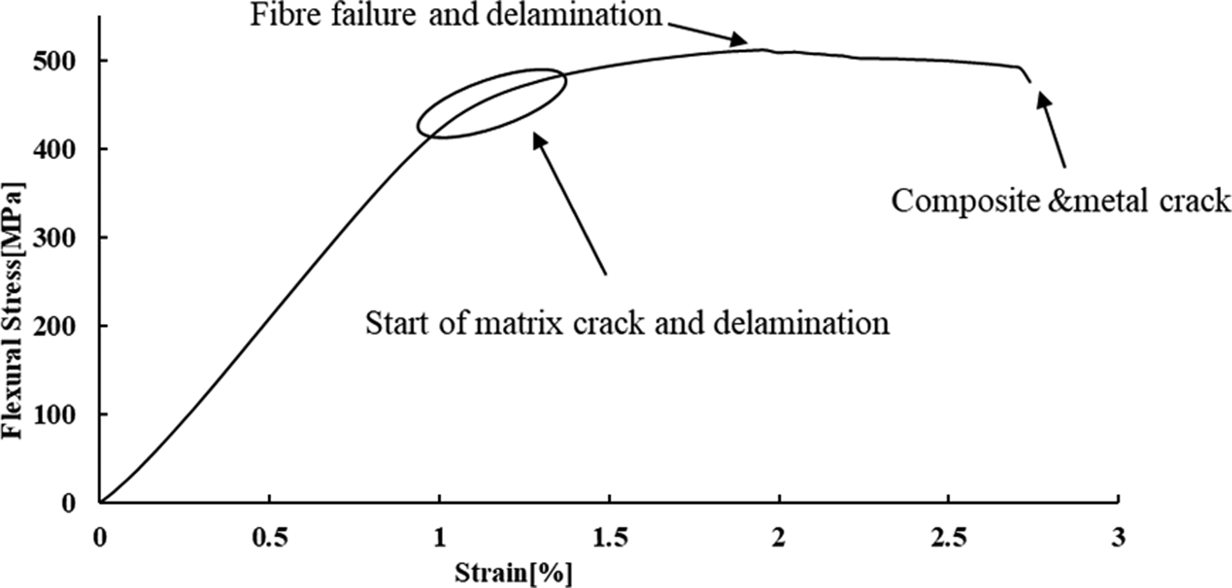
Typical flexural stress-strain curve of JuRAL.
Generally, during a flexural test of JuRAL, the flexural stress keeps on increasing with bending, then a specific point comes when aluminium alloy delaminates and break. The delamination starts as a result of matrix cracking. Once the matrix cracks, the delamination spread to a larger area. This delamination of the aluminium layer in the case of the bending test is due to an increase in shear forces. 26 In the FMLs, unlike FRC, there are other factors involve which determine the properties, e.g., delamination, metal cracking. The curves show that for JuRAL, there is a region of strain hardening where smaller strain is produced with higher force. Then in the second region, more strain is produced with little force up to failure, the reason for the strain hardening is that both aluminium and JFRC resist the bending. At maximum stress, the shear forces reach to the maximum extent. The maximum stress point can also be seen in the graph. There is a slight drop in the curve after reaching maximum stress; this drop is due to delamination and fibre breakage at the micro-level, after the initial fall in stress, the aluminium–composite start delamination. At the ultimate point, typically, the delamination spread to a larger area, the composite and non-loading side aluminium breaks. During the bending test, both aluminium sheets behave differently; the outer aluminium sheet cracks while the inner/loading side aluminium sheet tends to delaminate but not crack. Flexural properties of JuRAL are not only governed by properties of constituent materials, but the adhesion between aluminium and JFRCs also plays a significant part in determining the final properties. The trend of increase in flexural properties is the same for all types of JuRALs. The overall flexural properties of JuRALs were higher than the respective JFRCs, as shown in Table 5.
Flexural properties of JFRCs and JuRALs.
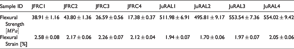
Figure 11 shows the average stress–strain curves for the flexural test of JFRCs and JuRALs.
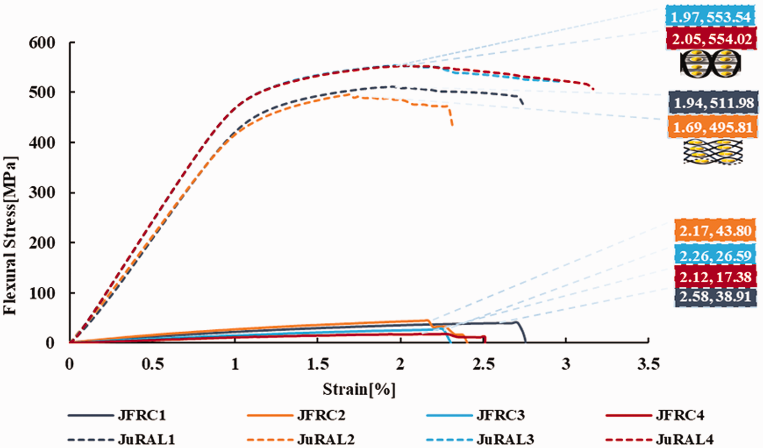
The average flexural stress-strain curves of JFRCs and JuRALs.
The flexural strength of JFRC1 and JFRC2 was more than JFRC3 and JFRC4. The JFRC1 and JFRC2 are LL interlocked while JFRC3 and JFRC4 are TT–interlocked, for LL–interlocked structures the yarns are placed in layers so more resistance to bending as compared to TT–interlocked structures, that is why the flexural strength of JFRC1 and JFRC2 was more than JFRC3 and JFRC4. On the contrary, the flexural strength of JuRAL3 and JuRAL4 was higher than JuRAL1 and JuRAL2 that was due to high MVF as explained earlier. Both structures of JWF and MVF have played the role to determine the flexural properties.
There is a sudden drop observed in the JuRAL2 curve after reaching ultimate flexural strength even though it MVF is higher than JuRAL1, this drop was due to the concentration of shear forces and debonding to a larger area.
The most common failure mechanisms in JuRALs were metal cracking, fibre failure, matrix cracking and delamination as observed in the case of the tensile test while in JFRCs the dominant failure mechanism were matrix cracking and fibre failure. The metal cracking was observed in the lower metal layer opposite to loading side, which was due to stress concentration. Matrix cracking indicated the brittle failure and this pattern of cracking was due to the nature of reinforcement material as already explained in the previous section. From Figure 12, it can also be seen that the failure region of JuRALs is limited to the area where the bending force is applied, the delamination was not spread to larger areas. This is due to: (a) excellent metal-composite bonding (b) 3 D woven reinforcement which reduce the crack propagation. 37
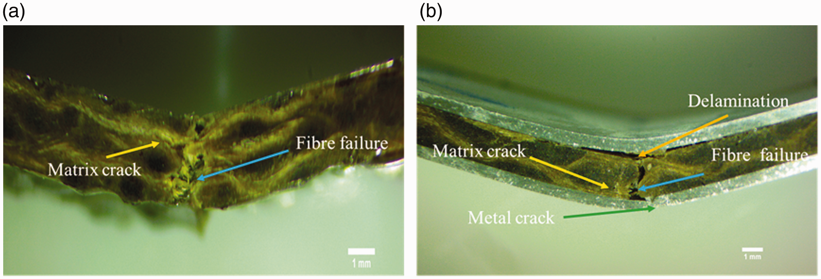
Microscopic images of tested specimens of (a) JFRC (b) JuRAL after the flexural test.
Conclusion
The T–peel test results and microscopic images had shown that there was excellent interfacial adhesion between composites and aluminium. The microscopic images of delaminated surfaces of aluminium and composites had shown that the delamination was mainly cohesive. The results of the T–peel test had also shown that the nature of manufacturing material mainly determines adhesion properties; the interlocking pattern of 3 D woven reinforcement does not affect the delamination properties. As the delamination only concerns the layer joining the aluminium and composite. When the properties of JFRCs were compared the through-thickness reinforced composites had better tensile properties due least crimp while layer-to-layer composite had better flexural properties, as more fibres are placed in the layers. The tensile properties of JuRALs were determined both by the type of structure of jute reinforcement and MVF. The JuRALs reinforced with TT–interlocked woven fabrics have shown higher tensile properties. Like tensile properties, the flexural properties of JuRALs were also determined by both the structures of jute reinforcement and MVF. Flexural properties were also higher for JuRALs reinforced with TT–interlocked 3 D woven fabrics. The type of 3 D reinforcement has governed the tensile and flexural properties, and JuRALs reinforced with TT–interlocked reinforcement has shown overall higher mechanical properties. The damaged samples and stress-strain curves indicated that the crack propagated due to matrix cracking and subsequent delamination between aluminium-composite. Another conclusion which can be drawn from the present study is that even with similar areal density and thread count the higher MVF can be achieved with TT interlocked structures as compared to LL interlocked structures due to less crimp and tight construction.
Footnotes
Acknowledgement
The authors would like to thank the National Centre for Composites Materials NCCM, National Textile University, Pakistan, for helping in the weaving of 3D Jute reinforcement, fabrication and testing of JFRCs and JuRALs.
Declaration of Conflicting Interests
The author(s) declared no potential conflicts of interest with respect to the research, authorship, and/or publication of this article.
Funding
The author(s) received no financial support for the research, authorship, and/or publication of this article.