
Abstract
Bistability is exhibited by an object when it can be resting in two stable equilibrium states. Certain composite laminates exhibit bistability by having two stable curvatures of opposite sign with the two axes of curvature perpendicular to each other. These laminates can be actuated from one state to the other. The actuation from the original post-cure shape to the second shape is called as ‘snap-through’ and the reverse actuation is called as ‘snap-back’. This phenomenon can be used in applications for morphing structures, energy harvesting, and other applications where there is a conflicting requirement of a structure that is load-carrying, light, and shape-adaptable. MW Hyer first reported this phenomenon in his paper in 1981. He found that thin unsymmetric laminates do not behave according to the predictions of the Classical Lamination Theory (CLT). The CLT is a linear theory and predicts the post-cure shape of thin unsymmetric laminates to be a saddle. MW Hyer developed a non-linear method called the “Extended Classical Lamination Theory” which accurately predicted the laminate to have two cylindrical shapes. Since then, a number of researchers have tried to identify the key parameters affecting the behavior of such laminates. Geometric parameters such as stacking sequence, fibre orientation, cure cycle, boundary conditions, and force of actuation, have all been studied. The objective of this research is to define a relation between the length, width and thickness of square and rectangular laminates required to achieve bistability. Using these relations, a 36 in × 36 in bistable laminate is fabricated with a thickness of 30 CFRP layers. Also, it is proved that a laminate does not lose bistability with an increase in aspect ratio, as long as both sides of the rectangular laminate are above a certain ‘critical length’. A bistable laminate with dimensions of 2 in × 50 in is fabricated. Further, for laminates that are bistable, it is necessary to be able to predict the curvature and force required for actuation. Therefore, a method is developed which allows us to predict the curvature of both stable shapes, as well as the force of actuation of laminates for which the thickness and dimensions are known. Finite Element Analysis is used to carry out the numerical calculations, which are validated by fabricating laminates. The curvature of these laminates is measured using a profilometer and the force of actuation is recorded using a universal test set-up.
Introduction
Hyer 1 first observed bistability in laminates of different sizes, shapes, stacking sequences and orientations. He found that thin unsymmetric laminates do not conform to the predictions of CLT. The CLT predicts all unsymmetric laminates to be saddle shaped, instead of the practically obtained cylindrical shapes. Since the CLT was unable to predict the shapes of some laminates, Hyer 2 developed a nonlinear theory known as the “Extended Classical Lamination Theory” (ECLT). A linear theory was ruled out because it would predict a unique shape instead of the observed two stable shapes. Since the out-of-plane deformation of the laminates were of the order of many laminate thicknesses, geometric nonlinearities were included through the strain-displacement relationship.
Since Hyer developed the non-linear ECLT, a number of researchers modified the theory to increase its accuracy and to make it applicable for laminates with angled plies and arbitrary lay-ups.3–8 Further, Mattioni et al. 9 and Pirrera et al. 10 considered higher order polynomials in order to take into account free edge effects. However, both found that FEA was more accurate than analytical models. A straightforward FEA model was presented by Tawfik et al. 11 and is modified and used in this research.
The dependence of bistability on the side length to thickness ratio was found by Hyer. 2 Thinner laminates were bistable at smaller side lengths whereas the side length had to be increased for thicker laminates to achieve bistability. 11 found that a non-dimensional critical length exists for square laminates which can be used to predict the critical length required for achieving bistability. However, this wasn’t validated by fabrication. 11 also found the relation between aspect ratio and bistability; it was found that rectangular laminates lost bistability at an aspect ratio of 8.
The objective of this research is to define four relationships between the geometry and behavior of bistable laminates using FEA and experiments:
Relation between side length and thickness of square laminates necessary to achieve bistability Relation between length and width of rectangular laminates necessary to achieve bistability Relation between size and thickness, and curvature of square and rectangular laminates Relation between size and thickness, and force of actuation of square laminates
The first two objectives let us know whether a laminate of a certain size and thickness is going to be bistable. The third objective allows us to predict the curvature of bistable laminates and the fourth objective allows us to predict the force of actuation of bistable laminates.
Methodology
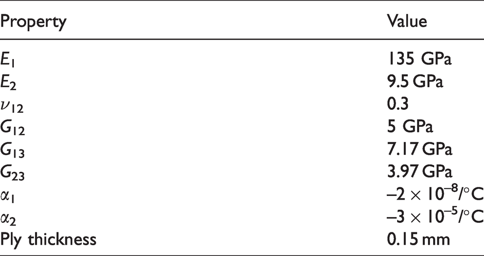
Abaqus software was used for all FEA simulations. Thick S4R shell elements were used. The prepreg material used in experiments was DA 409U/G35 150. However, all the material properties for this material were not provided by the manufacturer. The only material properties presented were tensile modulus and flexural modulus. It was found that these properties matched fairly well with the often used AS4/8552 prepreg, and therefore, the material properties of AS4/8552 were used, given in Table 1.
Material properties of AS4/8552 prepreg.
The bistability is tested in four steps:
Initial condition Cooling Snap-through loading Snap-through unloading
In the initial condition, the elevated curing temperature is applied. For rectangular laminates, the geometric center is fixed, whereas for square laminates, the centers of two opposite edges are restricted to move perpendicular to the laminate. This is done because perfectly square laminates always deform into an unstable saddle shape when fixed in the center. In the cooling step, the temperature is changed to a room temperature value, and the laminate settles into a stable equilibrium shape. In the third step, a snap through force in excess of the critical force is applied. In the fourth step, the force is released and the center is fixed. If the laminate is bistable, the shape after the fourth step is different than the shape obtained after the cooling step. If the same shape exists, the laminate is not bistable. The post-processing calculations for curvature and force are done on Matlab.
Since the laminate size is altered on each simulation, a constant number of elements equal to 900, corresponding to 961 nodes is chosen. This corresponded to a global element size of 1 mm2 for a square laminate of 30 × 30 mm2 dimensions. This ratio is kept constant in order to have the same number of elements for laminates of different sizes. For rectangular laminates, the same ratio of side length-to-global element size is maintained with respect to the smaller side. So, for example, a 150 × 150 mm2 square laminate has a global element size of 5 mm2, whereas a rectangular laminate with dimensions of 90 × 150 mm2 has a global element size of 3 mm2.
A standard vacuum bagging technique was used for laminate fabrication as recommended by Fibre Glast Developments Corporation. The material was cut and laid up according to the stacking sequence on an aluminium plate. The aluminium plate was first coated with a mold release. The laminate itself was then covered with a release film, peel ply, breather material, and finally a vacuum bag. Full vacuum was applied using a vacuum pump. The laminates were placed in an oven at 275 F for one hour and allowed to cool down naturally.
Post fabrication, a Nanovea ST500 profilometer was used for measurement of curvature and force of actuation was recorded using an ADMET universal test set-up shown in Figure 1.
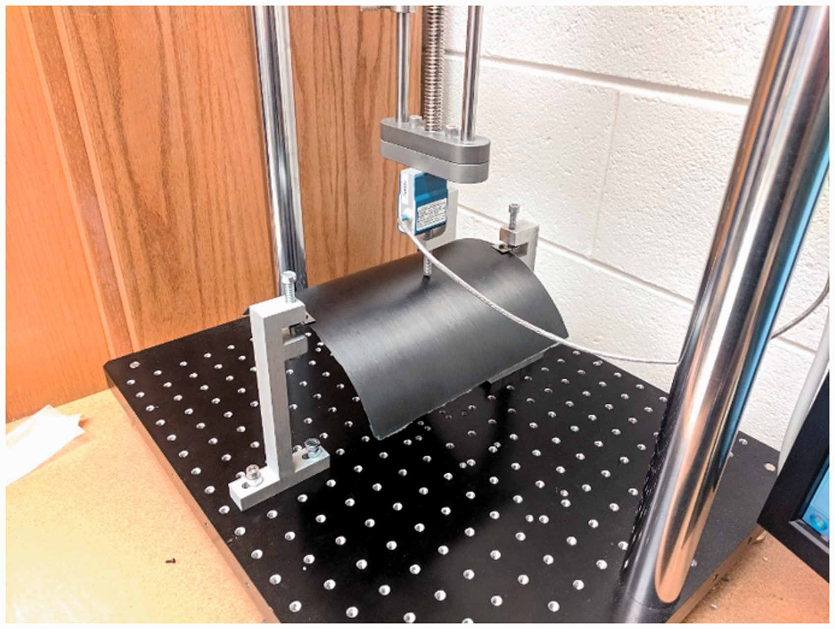
Set-up for measurement of force for snap-through. Figure shows an 8 × 8 in2, [0/90] laminate.
Simulations and experiments
The four objectives are investigated individually, and the results are as follows:
Relation between side length and thickness of square laminates necessary to achieve bistability
FEA approach
First, the non-dimensional bifurcation graph presented by Tawfik et al.
11
is replicated for the material properties given in Table 1 and shown in Figure 2. The non-dimensional parameters are as follows

Non-dimensional bifurcation graph (FEA).
The bifurcation point is found for a non-dimensional side length equal to 95.833. Using this, the critical length for a laminate with any given number of plies can be predicted.
Experimental approach
To validate this graph, several laminates were fabricated with thicknesses equal to two, four, and six plies. The sizes were such that the smallest laminate was saddle shaped, and with an increase in size, a bifurcation point is reached where bistability is achieved. This is shown in Table 2.
Results from fabricated laminates.
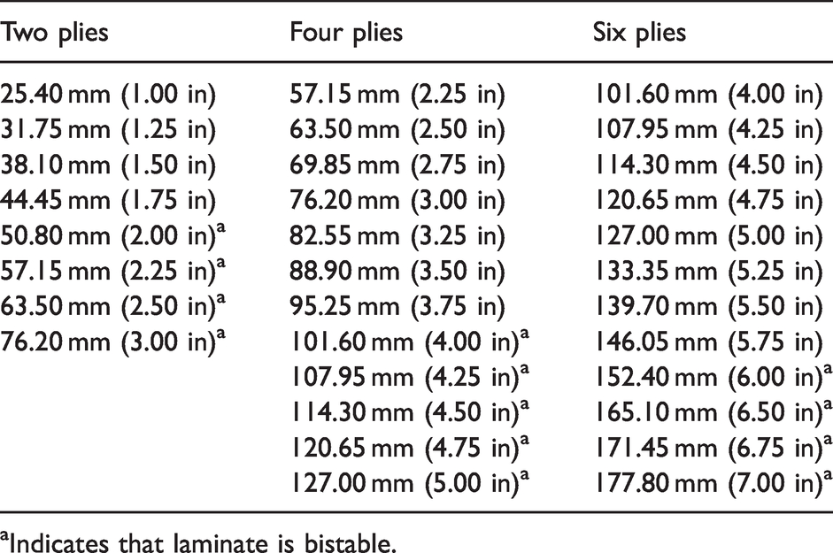
aIndicates that laminate is bistable.
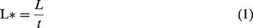
The bifurcation points were found at 2 in (50.8 mm) for two plies, 4 in (101.6 mm) for four plies, and 6 in (152.4 mm) for six plies. The out of plane deformation was scanned using the profilometer for each laminate. For non-bistable laminates, only one shape and the corresponding deformation was measured. For bistable laminates, the out-of-plane deformation was measured for both stable shapes. These values were made non-dimensional by using equations (1) and (2), and the results are plotted as shown in Figure 2.
As seen, the experimental results do not exactly match with the FEA results. The reasons for this discrepancy are discussed later. The non-dimensional bifurcation was found at three different points for two, four, and six plies. The values are equal to 185.2, 198.4, and 202.84, respectively, with an average of 195.48. Using this value for L* and by using the post cure lamina thickness of 0.12 mm, according to equation (1), a square laminate with eight plies would have to be above 191.9 mm, or 7.39 in to be bistable. Two square laminates with stacking sequences of [04/904] and side lengths equal to 7 in and 8 in were fabricated. It was found that the 7 in laminate was not bistable whereas the 8 in laminate was bistable. Thus, from this data, it was concluded that the critical ratio between number of plies and length in inches was 1:1, i.e., a square laminate with ‘X’ number of plies would have to have a side length of ‘X’ inches to be bistable.
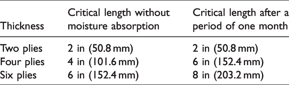
However, it was found that moisture absorption caused a shift in the bifurcation point as shown in Table 3. Based on the data given in Table 3, a number of plies-to-side length ratio of 1:1.2 was used for fabrication of large bistable laminates, meaning that a non-dimensional critical length was placed at a value of 254. Using this, three large bistable laminates were fabricated: a 12 × 12 in, 10 ply laminate, a 24 × 24 in, 20 ply laminate, and finally a 36 × 36 in, 30 ply laminate. All three were found to be bistable as shown in Figures 3 to 5.
Increase in critical length due to moisture absorption.
Non-dimensional bifurcation graph (experiment).
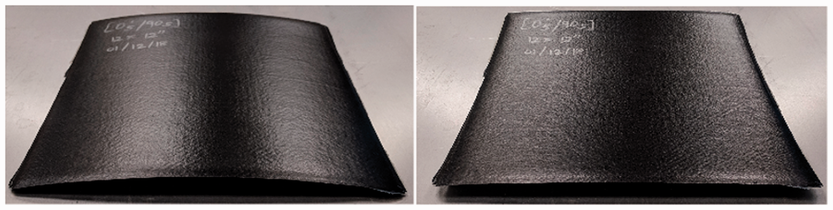
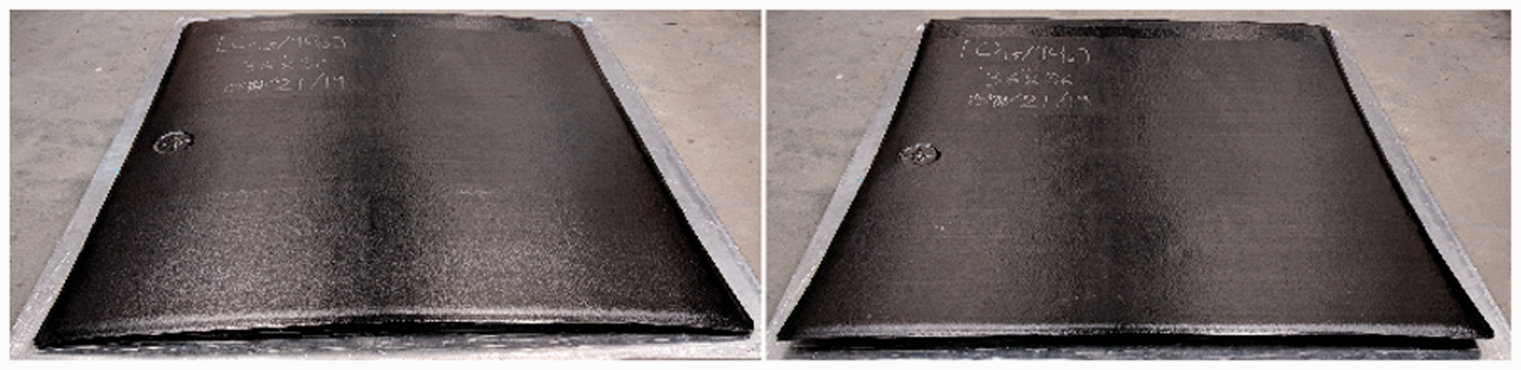
Bistable [05/905], 12 × 12 in 2 laminate.
Bistable [010/9010], 24 × 24 in 2 laminate.
Discussion
A similar trend was observed between FEA and experimental results, however, a clear difference exists between the values. The non-dimensional critical length found from FEA was equal to 95.833 whereas the average value found from experiment was equal to 199.9. The possible reasons for this difference are as follows:
The material properties of AS4/8552 were used for the FEA simulation, whereas the actual material being used was DA 409U/G35 150. This was because all of the necessary material properties were not provided by the manufacturer of DA 409U/G35 150. The experimental fabrication was done using hand lay-up. This introduces various defects such as fibre misalignment, difference in lamina sizes, inaccurate stacking of different layers on top of each other causing inaccurate stacking sequence toward the edges and variation in the [0
n
/90
n
] lay-up, introduction of air bubbles within lamina layers, and so on. There exists a variation in the epoxy content of each laminate. This variation exists because of non-uniform distribution of pressure and heat during vacuum bagging, material aging, and use of different batches of prepreg rolls for different laminates. Several other factors presented by Betts et al.
12
play a role in causing mismatch between the ideal FEA simulation and fabricated laminates.
Further, moisture absorption caused an increase in the critical length and this was taken into consideration while fabricating larger laminates. The moisture absorption data presented by Etches et al. 13 was used for this. All these factors need to be included in the FEA model to get better correlation between FEA and experiment.
Relation between length and width of rectangular laminates necessary to achieve bistability
FEA approach
The aspect ratio was varied by keeping one side constant and increasing the other one. In the previous section it was found that square, [0/90] laminates with side length less than 24 mm (0.95 in) were not bistable. For rectangular laminates, a similar trend was observed – laminates with one side less than 24 mm (0.95 in) were not bistable. Therefore, the side that was kept constant was given a value of 24 mm (0.95 in), and the other side was increased in magnitude starting from 24 mm such that the aspect ratio was varied as given in equation (3)

It was found that laminates up to an aspect ratio of 1:16 were bistable. Beyond this point, the laminate became and extremely thin strip and the FEA stopped converging. It should be noted that the post-cure curvature of thin laminates is so high that a simple point force in the center did not make the laminate snap-through. For example, consider a [0/90], 24 × 192 mm2 laminate. Its post-cure shape is shown in Figure 7 and its failure to snap-through with a simple point force is shown in Figure 8.
The application of force was therefore modified such that it was applied in two steps. First, a force is applied on two opposite edges, such that the laminate is ‘opened’ like a newspaper, then a point force is applied in the center. The post snap-through shape obtained using this snap-through process is shown in Figure 8.
The post-cure shape for all rectangular laminates was such that the longer side was curved and the shorter side had a nearly straight edge, as shown in Figure 6, and the post snap-through shape was as shown in Figure 8. An increase in out of plane deformation with an increase in AR was observed for the post-cure shape, whereas the out of plane deformation post snap-through remained fairly constant, with a slight increase. This is shown in Figure 9.
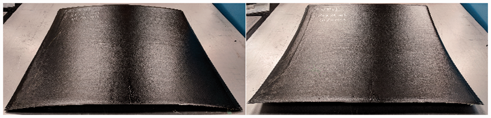
Bistable [015/9015], 36 × 36 in 2 laminate.
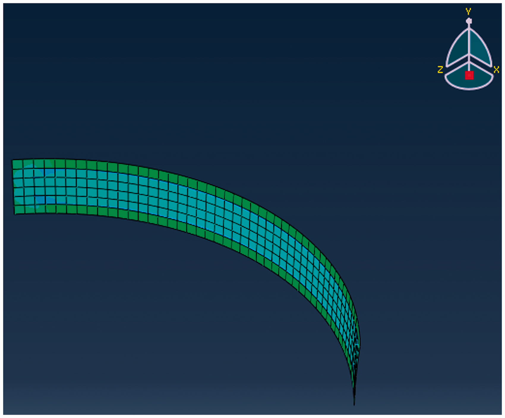
Post cure shape of a 24 × 192 mm2, [0/90] laminate.
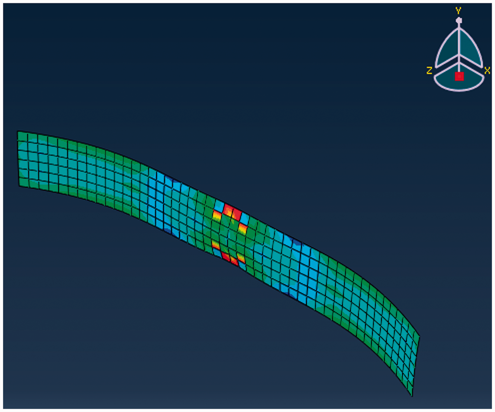
Failure of snap-through propagation of 24 × 192 mm2, [0/90] laminate.
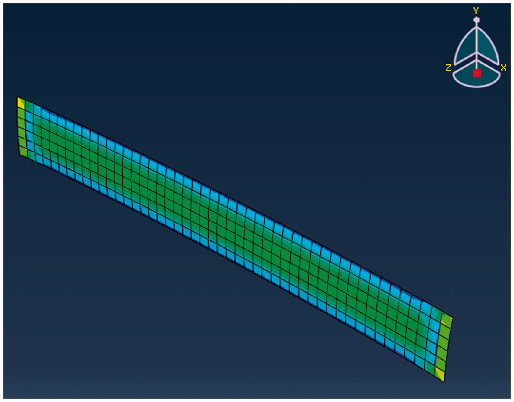
Post snap-through shape of [0/90], 24 × 192 mm2 laminate.
For a laminate to lose bistability, the out of plane deformation would have to reduce with an increase in AR, with a loss in bifurcation at a certain point. The data obtained thus far shows that an increase is AR will not cause a loss in bistability, since there is an increase in out of plane deformation for both shapes. Thus, it can be concluded that the aspect ratio can be increased till infinity and the laminate will not lose bistability, as long as both sides are above the critical length.
Experimental approach
Four laminates with varying AR’s were fabricated with stacking sequences of [0/90]. The sizes were 6 × 36 in2, 4 × 32 in2, 3 × 45 in2, and 2 × 50 in2, i.e. AR’s of 1:6, 1:8, 1:15, and 1:25. All laminates were bistable, as shown in Figures 10 and 11.
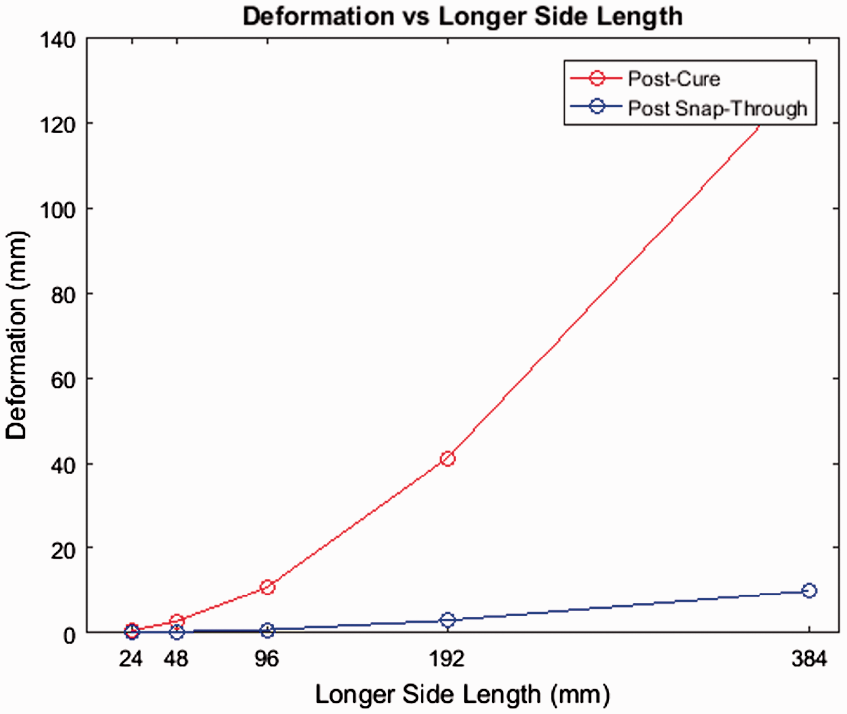
Out of plane deformation post curing and post snap-through with increase in AR.
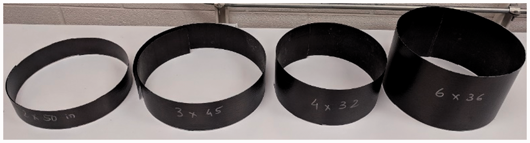
(From right) post cure shape of laminates with AR’s 1:6, 1:8, 1:15, and 1:25.
To fabricate the laminate with the largest AR of 1:25, data obtained in previous sections is used. The minimum side length for a square, [0/90] laminate to be bistable was 2 in. With one side constant at 2 in, the other side was fabricated to be 50 in. This was the maximum length that could fit inside the dimensions of the curing oven.
Discussion
Using the FEA model, it was possible to prove that a [0/90] laminate with an aspect ratio of 1:16 (24 × 384 mm2) was bistable. It was not possible to simulate a laminate with higher aspect ratios since the FEA stopped converging. Further, it was seen that the curvature did not reduce with an increase in aspect ratio, indicating that laminates with even higher aspect ratios would be bistable. This was proven using fabricated laminates. A [0/90], 2 × 50 in 2 laminate with an aspect ratio of 1:25 was fabricated and shown to be bistable. Therefore, we can conclude that a rectangular laminate will not lose bistability for any aspect ratio as long as both sides are above the critical length.
Relation between size and thickness, and curvature of square and rectangular laminates
FEA approach
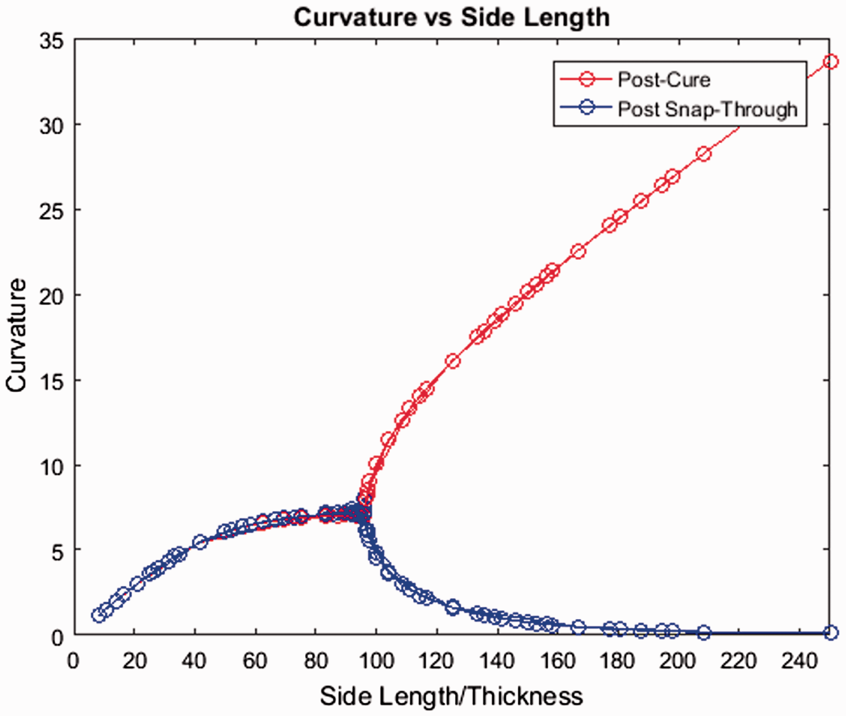
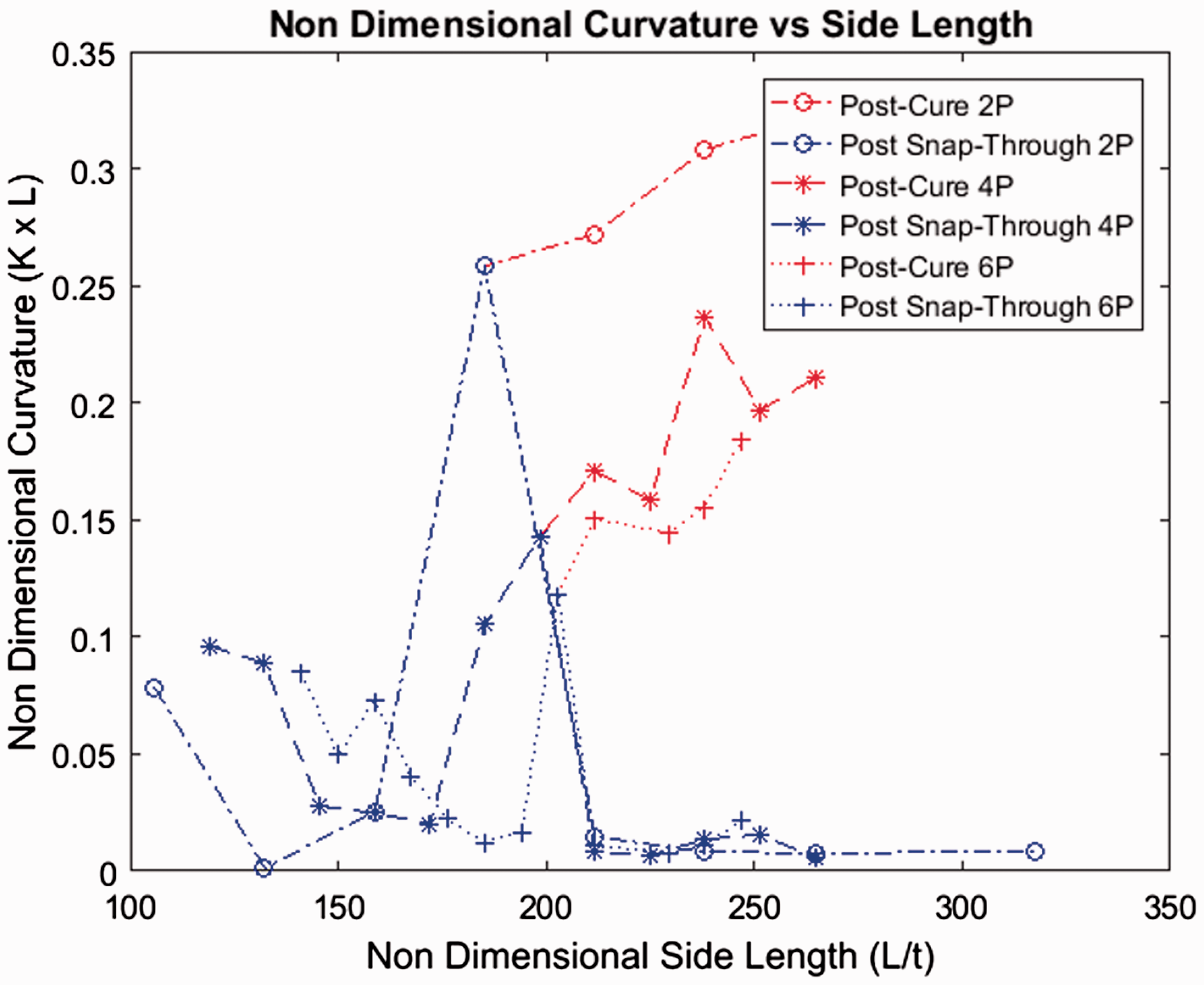
For square bistable laminates, assuming an ideal geometry and lay-up, the curvatures for both shapes is predicted to be equal using the FEA model. This curvature can be predicted using the graph shown in Figure 1. The red curve is the predicted curvature of square laminates.
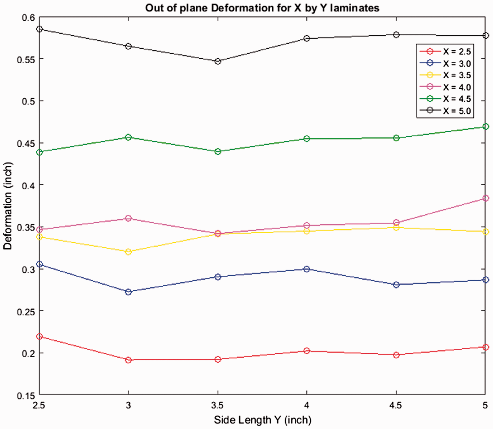
For rectangular laminates, let us say that one side has a dimension of ‘X’ units and the other side has a dimension of ‘Y’ units. In the previous section, it was seen that keeping the ‘X’ side constant at 24 mm and varying the ‘Y’ side in magnitude did not affect the out of plane deformation of one of the laminate shapes. This shape was the one in which the side ‘X’ (24 mm) was curved and side ‘Y’ was straight.
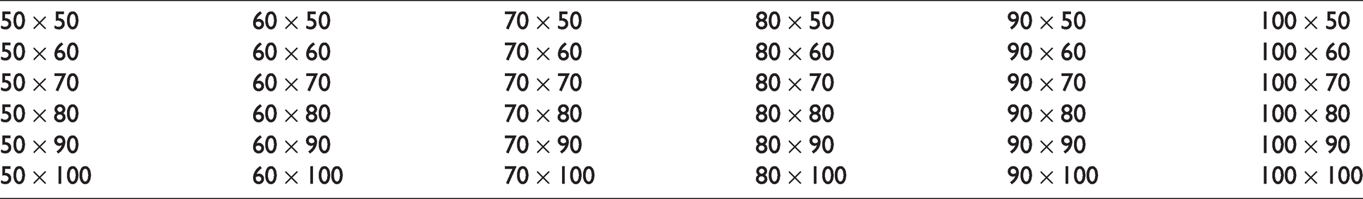
For further examples, consider the rectangular laminates with dimensions ‘X by Y’ given in Table 4. Every laminate is bistable and has two shapes. For ease of explanation, let us say that the shape where side X is curved is called as an ‘X by Y’ laminate whereas the shape where side Y is curved is called a ‘Y by X’ laminate. Therefore, a ‘50 mm × 100 mm’ laminate means that the side with a value of 50 mm is curved and the 100 mm side is straight. For a ‘100 mm × 50 mm’ laminate, the 100 mm side is curved and the 50 mm side is straight.
List of rectangular laminates for FEA (all dimensions in mm).
Plotting the out of plane deformation for each of these shapes gives us the result shown in Figure 12. It can be seen that the out of plane deformation remains approximately constant for all shapes in which the dimension X remains constant with variation in Y.
(From top) Post snap-through shape of laminates with AR’s 1:6, 1:8, 1:15, and 1:25.
Therefore, it can be concluded that for a rectangular laminate ‘X by Y’, the two shapes will be as following:
The side ‘X’ will be curved and side ‘Y’ will be straight, and the magnitude of curvature will be equal to that of a square ‘X by X’ laminate. The side ‘Y’ will be curved and side ‘X’ will be straight, and the magnitude of curvature will be equal to that of a square ‘Y by Y’ laminate.
Experimental approach
The same approach is followed experimentally but with different values of X and Y. The values of X and Y were increased to allow for human error in lay-up, and the loss of curvature due to the reasons explained earlier. The values of X and Y were as shown in Table 5 and the fabricated laminates are shown in Figure 13. The figure shows 21 laminates, with the rectangular laminates giving two different shapes and data points. Therefore, in total we obtain 36 data points from the laminates to match the 36 shapes given in Table 5.
List of rectangular laminates for experiment (all dimensions in inches).
Out of plane deformation of ‘X by Y’ laminates (FEA).
The out of plane deformation is measured using the profilometer and the results are plotted as shown in Figure 14.
Fabricated laminates for dimensions given in Table 5.
Discussion
A method was developed to be able to predict the curvature of square and rectangular laminates. Using the graph shown in Figure 1, it is possible to predict the curvature of square laminates.
For rectangular ‘X by Y’ laminates, it was proven that there exist two shapes such that:
The side ‘X’ will be curved and side ‘Y’ will be straight, and the magnitude of curvature will be equal to that of a square ‘X by X’ laminate. The side ‘Y’ will be curved and side ‘X’ will be straight, and the magnitude of curvature will be equal to that of a square ‘Y by Y’ laminate.
Relation between size and thickness, and force of actuation of square laminates
FEA approach
The boundary conditions described in the methodology section were used to obtain the FEA results and the post processing of the data to find the snap-through force was done using the method described by Tawfik et al. 11 For laminates with a stacking sequence of [0/90], the side length was varied starting from the critical length of 24 mm up to a maximum side length of 150 mm. The snap-through was found for each laminate and the results are as shown in Figure 15.
Out of plane deformation of ‘X by Y’ laminates (experiment).
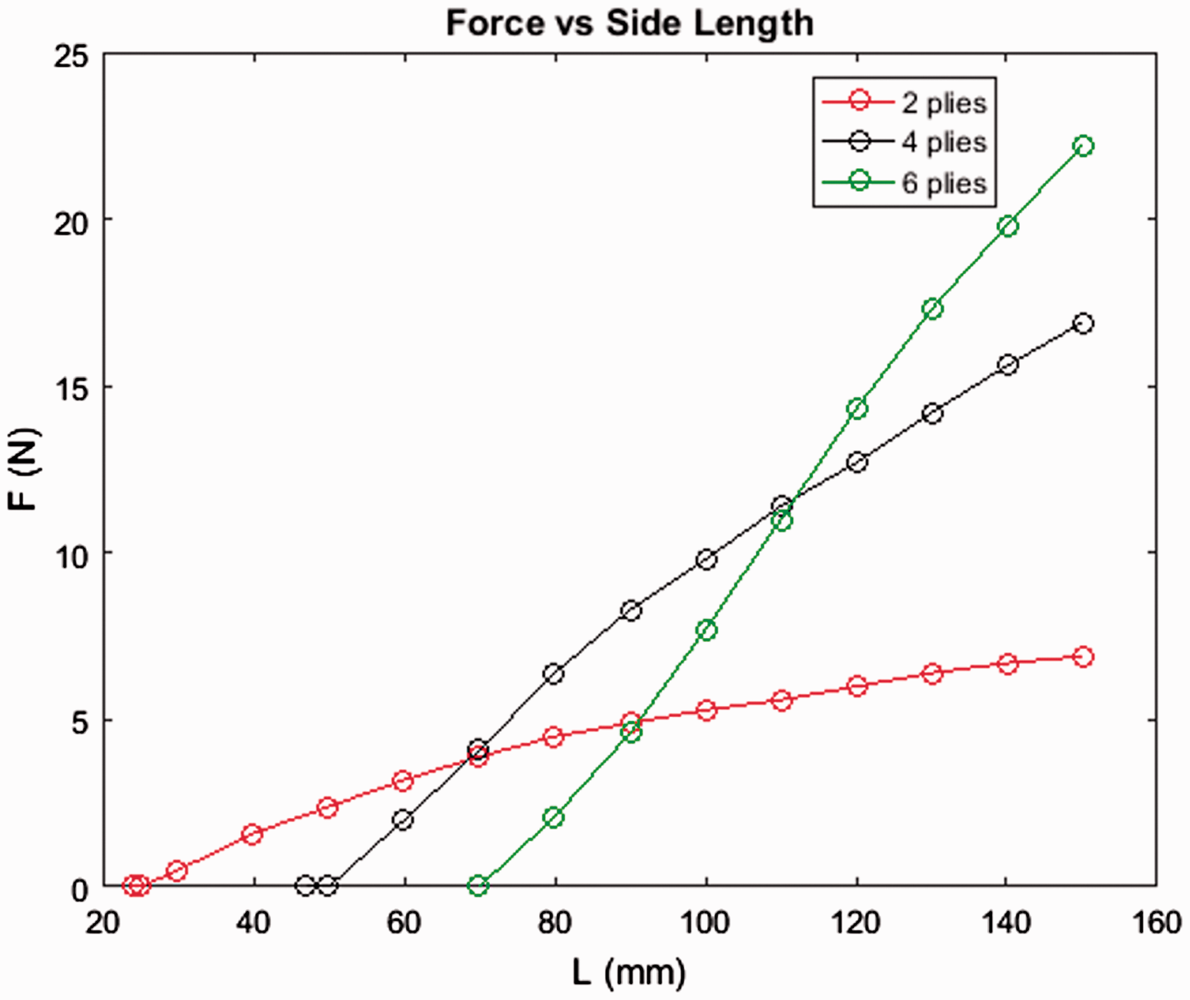
Further, the thickness was changed to four plies, i.e. a stacking sequence of [02/902], and length was varied from the critical length for two plies of 47 mm up to a maximum length of 150 mm. Also, for six plies, i.e. a stacking sequence of [03/903], the length was varied from 70 mm up to 150 mm. Results for two plies, four plies, and six plies are plotted on a graph shown in Figure 16. It can be seen that there is no clear relation between the thickness and force for the data shown in the figure. For example, for a side length of 80 mm, the snap-through forces are 4.5 N for two plies, 6.4 N for four plies, and 2.1 N for six plies. Which means that the force for snap through has the relation F4 plies > F2 plies > F6 plies. But, for a side length of 100 mm, the snap-through forces are 5.3 N for two plies, 9.8 N for four plies, and 7.7 N for six plies giving a relation of F4 plies > F6 plies > F2 plies. This suggests that thickness alone is not affecting the snap-through force and curvature difference between two stable shapes also plays a role since the curvature reduces as thickness is increased.
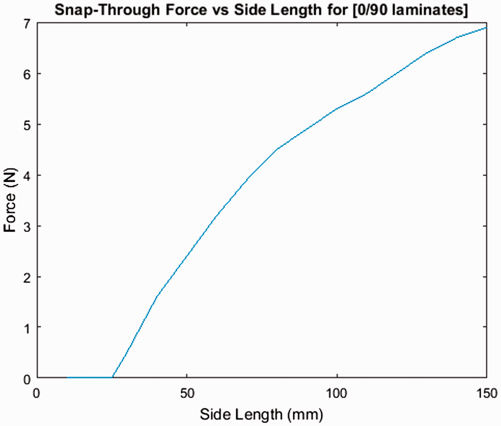
Snap-through force vs side length for [0/90] laminates.
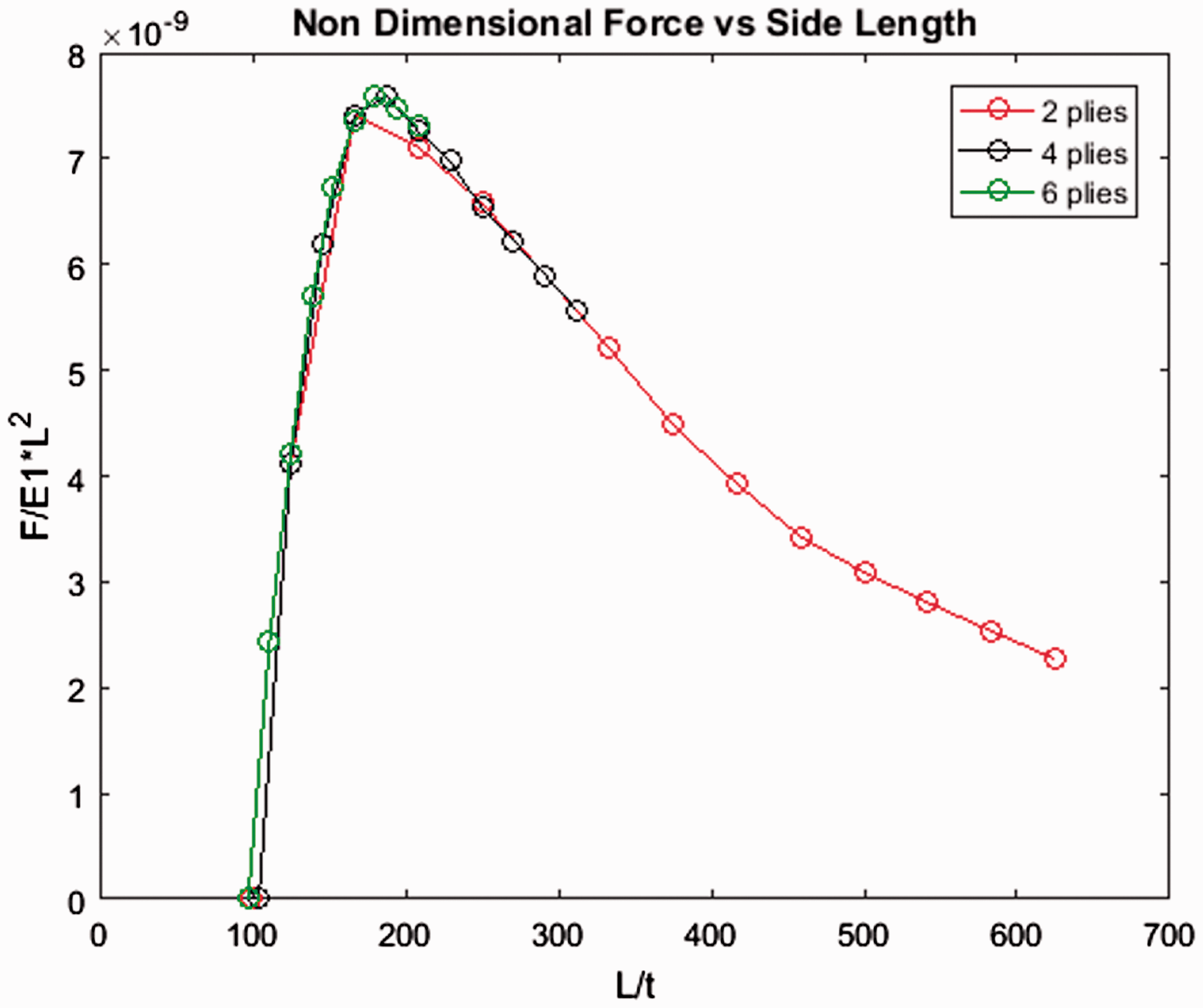
Therefore, we introduce non-dimensional parameters to make the parameters unitless. The length is divided by the thickness, and the force is divided by the square of the length and also divided by E1, which is the Young’s modulus in the direction of the fibre orientation. This is given in equations (4) and (5)
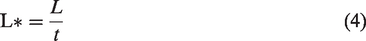
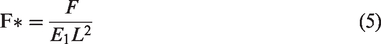
We choose E1 to make the parameter unitless. Since E2 is the Young’s modulus perpendicular to the fibre direction, the amount of epoxy affects its value. Therefore, since E1 is fairly constant, it is used to make the force non-dimensional. Plotting these non-dimensional parameters gives us the results shown in Figure 17.
Force vs side length for two, four, and six plies (FEA).
Using this graph, it is possible to predict the required force of actuation for any square laminate. For example, a square laminate with 50 plies and a side length of 50 in would have a ‘L/t’ ratio of 211.667, giving a ‘F/E1L2’ ratio of 7.11e−9. This allows us to calculate the force to be 2.4 N.
Experimental approach
The ADMET Universal test set up is used to conduct experimental snap-through tests. Tests are conducted for laminates with two, four, and six plies.
The data points include nine laminates for two plies ranging from 3 to 9 in, seven laminates for four plies ranging from 4 to 10 in, and five laminates for six plies ranging from 6 to 10 in. The maximum length is 10 in because of the size limitations of the ADMET test up. The minimum length is set by the critical length found earlier. Plotting the snap-through forces for each laminate gives us the results shown in Figure 18. Logarithmic trend lines are added for easier comparison with the FEA results shown in Figure 16. The same non-dimensional parameters given in equations (4) and (5) are used, and the results are shown in Figure 19. Figure 20 shows the non-dimensional experimental data as a comparison to Figure 18. The trend is similar, but the consistency and smoothness of the curvature is varied for the experimental results.
Non-dimensional force vs side length (FEA).
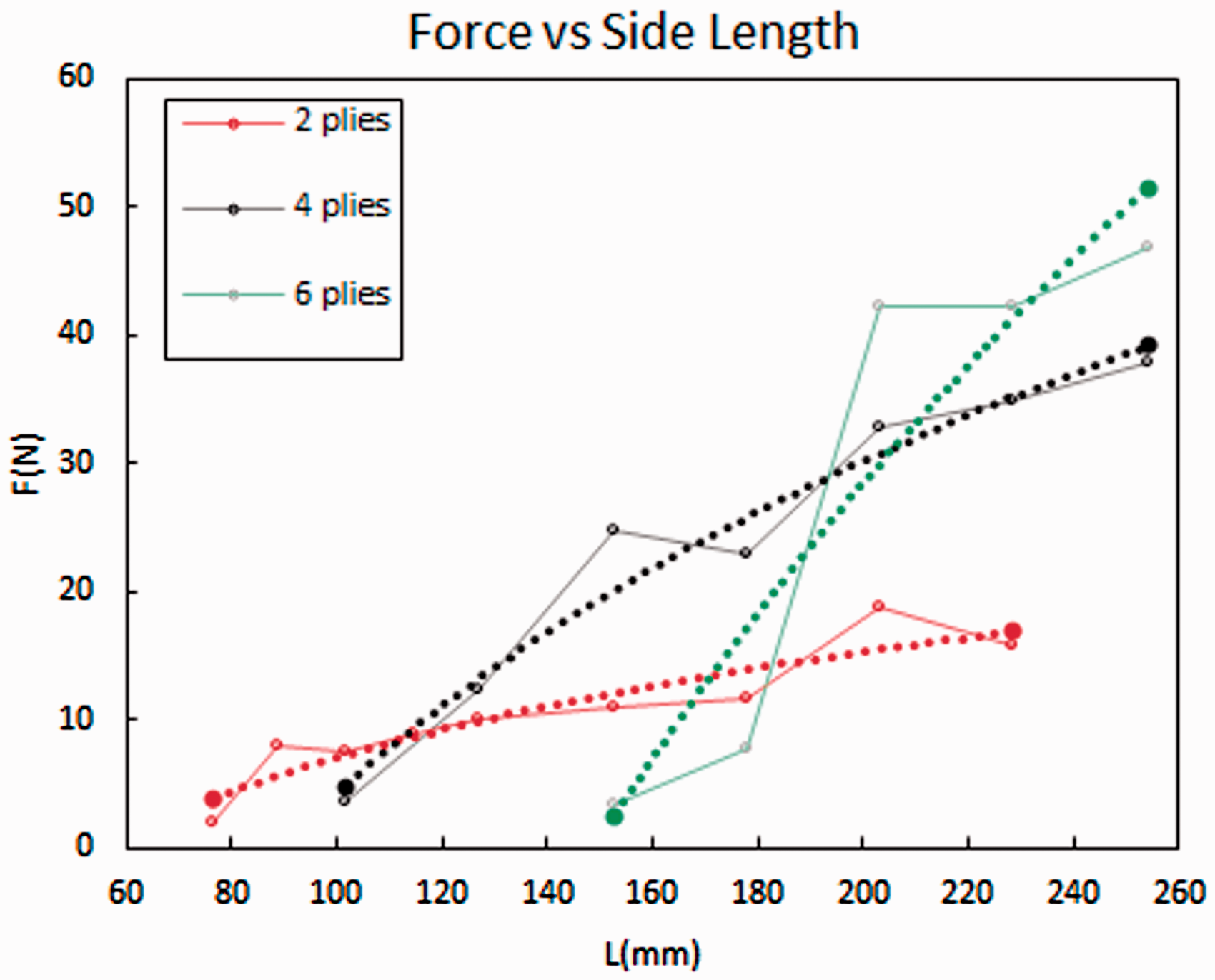
Force vs side length for two, four, and six plies (experiment).
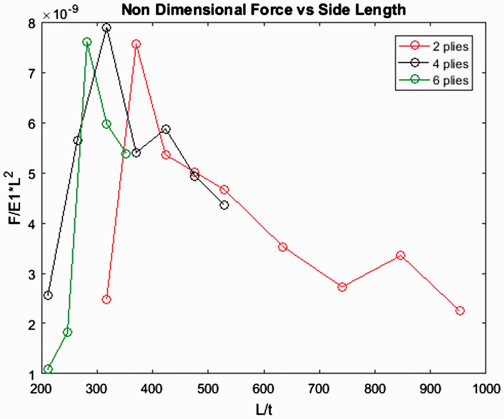
Non-dimensional force vs side length (experiment).
Discussion
As established in the second section of this chapter, there is a difference between the magnitude of curvature predicted by FEA and the curvature that is found in fabricated laminates. More specifically, the critical length found from FEA is lower than the critical length found from experiment. Because of this, it is not possible to directly compare the FEA results for the prediction of snap-through force with the experimentally obtained values. There are two reasons for this:
For the FEA analysis, there is a higher limit on the side length of the square laminates for conducting a snap-through test. Beyond this limit, the laminate has a very high value of curvature and starts to coil around itself, making an application of point force in the center of the laminate ineffective. This was shown in Figure 3 for rectangular laminates. For the experimental approach, there is a lower limit on the side length of the square laminates imposed by the critical length.
Therefore, it is not possible to conduct a snap-through test using FEA and experiment on a laminate of the same size and stacking sequence. However, using different sizes of laminates, it was possible to prove that the trend seen in the FEA results is also found in the experimental results, giving us two conclusions:
The magnitude of force necessary for snap-through is a function of thickness, and the square of the side length. Introducing non-dimensional parameters by dividing the side length on the X axis by the thickness and diving the force on the Y axis by the square of the side length and the Young’s modulus E1, the curves for the force vs side length for different number of plies collapse into a single curve.
Based on this, it is possible to predict the force of actuation for a square laminate for which the side length and thickness is known.
Conclusion and future work
There were four objectives in this research. The results from FEA and experiment are summarized below.
Relation between side length and thickness of square laminates: A non-dimensional critical length of 95.833 was found using FEA. Using this value, the minimum side length for square laminates of any thickness required to achieve bistability can be predicted. Experimentally, the non-dimensional critical length was found to be 199.99. There are many possible reasons for this difference, including incorrect material properties in the FEA analysis and fabrication defects caused by inaccurate hand lay-up. Using this non-dimensional critical length and taking into account the effect of moisture absorption, two thick bistable laminates were fabricated: one, with a stacking sequence of [010/9010] and side length of 24 in, and two, with a stacking sequence of [015/9015] and side length of 36 in. Relation between length and width of rectangular laminates: It was found that aspect ratio does not cause a rectangular laminate to lose bistability, as long as both sides are above the critical length. Laminates with aspect ratios of 1, 2, 4, 8, and 16 were simulated using FEA and it was found that the curvature slightly increased with an increase in aspect ratio, proving that laminates with even higher aspect ratios would be bistable. Experimentally, laminates with aspect ratios of 6, 8, 15, and 25 were fabricated and proven to be bistable. Prediction of curvature: The graph of curvature Vs side length for different number of plies collapsed into a single curve upon introducing non-dimensional parameters. Using this graph, it is possible to predict the curvature of any square laminate for which the thickness and side length is known.
For any rectangular ‘X by Y’ laminate it was proven that there exist two shapes such that:
The side ‘X’ will be curved and side ‘Y’ will be straight, and the magnitude of curvature will be equal to that of a square ‘X by X’ laminate. The side ‘Y’ will be curved and side ‘X’ will be straight, and the magnitude of curvature will be equal to that of a square ‘Y by Y’ laminate. Prediction of force: A non-dimensional study was performed on the relation between force and side length. It was found that the force is a function of thickness as well as side length. Introducing non-dimensional parameters made the graph between force and side length to collapse into a single curve for different number of plies. Using this curve, it is possible to predict the force of actuation of any square laminate knowing its thickness and side length. This was validated by fabricating and testing laminates of various stacking sequences and thicknesses. It was found that while there was good correlation between FEA and experiment, there was a difference in the values obtained for both.
Future work
While good correlation was found between numerical results and experimental results, the effects of manufacturing defects and environmental conditions were found to be the reasons for a mismatch between the results. Therefore, an analytical model must be used that would allow prediction of the behavior of a laminate with a variation in moisture content, temperature and material properties. A benefit of an analytical model will be that the volume fractions of the fibers and the epoxy can be varied, allowing an investigation into their effects on the curvature.
The prediction of bifurcation points and curvature was based on free edge boundary conditions. In any application, all edges will never be free and therefore the effect of clamping one or more sides on the curvature and/or the loss of bistability should be investigated.
The benefit of bistable composites is that they can be actuated from one state to the other. In an application where there is repeated actuation, fatigue stresses will have an effect on the behavior of the laminate. This should also be investigated.
Footnotes
Declaration of Conflicting Interests
The author(s) declared no potential conflicts of interest with respect to the research, authorship, and/or publication of this article.
Funding
The author(s) received no financial support for the research, authorship, and/or publication of this article.