
Abstract
The high strain rate tensile response of titanium-based fiber metal laminates (FMLs), consisting of layers of titanium Ti-6Al-4V alloy sheet and glass fiber reinforced composites, is examined. A hand layup method is used to fabricate four different layups of FMLs, exhibiting the same thickness of the total metal layer. A split Hopkinson tensile bar apparatus is used to load titanium and composite under a high strain rate to obtain baseline data. High-speed digital image correlation is used to measure the strain directly on the specimen gage region. The elastic-plastic response of FMLs up to maximum stress is predicted by the classical laminated plate model and orthotropic plasticity model. This is followed by a behavior considering the mechanics of delamination. The results show that the layup sequence of titanium-based FMLs considerably affects the failure behavior of composites following ultimate strength. This strength increases at high strain rates and seems higher for titanium-based FMLs than aluminium-based FMLs. This is primarily caused by the rate-dependent response of the titanium and composite. The failure strain of glass fiber reinforced epoxy (GFRP) constituent, failure strain, and toughness of FMLs are affected by isolating composite layers by metallic layers within FMLs and are found to be rate sensitive. Isolation of composite layers from one another by metallic layers results in more progressive failure of FMLs. The proposed models are validated with experiments of aluminium-based FMLs available in the literature.
Keywords
Introduction
Fiber metal laminates (FMLs) consist of alternating layers of thin metallic sheets and fibers. FMLs combine the durability of metals with impressive fatigue and fracture properties of fiber-reinforced composite materials.1,2 GLARE-1 (7475-T761, 0°/0°fibers) offers a tensile strength almost three times higher than the plain aluminium alloy. 3 The use of glass fiber reinforced aluminium laminates (GLARE) for over 400 m2 of the A380’s fuselage crown secures 25% weight saving over a conventional structure made of aluminium. This is the primary driving force behind the development of FMLs. FMLs have been reported to exhibit crack growth rates 10 to 100 times slower than their monolithic aluminium constituents.4,5 FMLs have high residual and blunt notch strength, flame, fatigue and corrosion resistance, and impact strength.
Titanium (Ti) alloy is well known for its high strength to weight properties and is much stronger than aluminium at high temperatures. It is the optimal material for high-speed aerospace applications. Researchers at NASA have determined the operating temperature for a with high-speed research program to reach 177 °C. 6 This temperature range exceeds a level at which aluminium can retain its strength. With both early laminates, possessing aluminium exteriors, aramid fiber reinforced aluminium laminates (ARALL) and GLARE prove inadequate for such applications. To meet the need for strong, lightweight, damage tolerant, and high-temperature material, a hybrid composite laminate composed of Ti, graphite fibers, high-temperature epoxy is manufactured and termed as hybrid titanium composite laminate (HTCL), or titanium graphite (TiGr). HTCL is originally designed with a specific application of potential skin material for a high-speed civil transport program. Current FMLs are not useful in temperature ranges required for supersonic aircraft. With the addition of titanium to composite layers, they are protected from environmental effects such as oxidation and moisture absorption as well as potentially provide improved impact resistance and bearing properties.
Harding and Welsh 7 have reported that the tensile properties of unidirectional carbon fiber reinforced epoxy (CFRP) such as modulus, fracture strength, and failure mode are found to be strain rate insensitive up to about 1000/s. However, in the case of 0° and 45° glass fiber reinforced epoxy (GFRP) specimens with woven-roving reinforcement, failure strength and failure strain increase significantly with the former specimen exhibiting noticeably increased initial modulus at strain rates under the impact. Ou et al. 8 have reported that the tensile strength and toughness of glass yarn are increased by 88% and 474% with strain rate changing from 1/600 to 40/s. Manoj and Naik 9 have reported that the tensile strength of woven fabric E-glass/epoxy laminated composite along warp direction, composite with unidirectional plies along and across fiber direction, and epoxy resin along the in-plane direction increases with a strain rate of up to 470/s. More studies widely reporting fiber and composite rate-sensitive behavior can be found in the literature.10–15 Yatnalkar 16 has reported that for titanium alloy Ti-6Al-4V sheet, the tensile yield strength and fracture strength increase whereas the failure strain decreases with strain rate from 0.0001 to 1500/s. Peirs et al. 17 have reported that Ti-6Al-4V exhibits lower strain hardening with tensile yield and ultimate strengths increasing with a strain rate of up to 1007/s.Kakogiannis et al. 18 have reported that the plastic stress of the Ti-6Al-4V alloy sheet increases with a strain rate of about 500/s. Verleysen and Peirs 19 have reported that the tensile strength and fracture strain of the Ti-6Al-4V sheet increases and decreases with a strain rate of about 360/s during in-plane loading. More studies reporting the strain rate sensitivity of titanium alloy Ti-6Al-4V can be found in the literature.20–22 From the above studies, it can be stated that the FMLs consisting of layers of GFRP and titanium alloy Ti-6Al-4V sheets that are rate sensitive, will be having a more predominant strain rate effect on their behavior.
However, the tensile behavior of aluminium-based FMLs to dynamic loading has received consideration in most of the studies. Wu 2 has reported that the ultimate tensile strength, approximate modulus, and fracture strain of ARALL-1 laminates are strain rate insensitive at room temperature (75 °F) and 180 °F, while these properties are found to be strain rate sensitive at 250 °F. Vlot 23 has reported that the increased minimum cracking energy of GLARE 3 is more pronounced than aluminium (Al) 2024-T3 with increased ultimate tensile stress exhibited by the former specimen at a loading rate of 69/s. Vlot 24 has also found that the strength of similar cross-ply glass fiber-based FML in the 0° direction increases by 11% under a rate of 222/s. Zhou et al. 25 have reported that the yield strength, tensile strength, and failure strain of kevlar fiber reinforced aluminium laminates (KRALL), and pre-stressed KRALL(P) increase with strain rate. McCarthy et al. 26 have reported that for 0° tests on aluminium-based FML, the ultimate load capacity increases with approximately doubled ultimate extension with the rate of 3300/s. However, for 45° tests on FML, maximum extension is seen to be substantially increased and a minor increase in load capacity with strain rate. Zhou et al. 27 have reported that a strain rate insensitivity is observed for carbon fiber (Cf), but Cf/Al composite is having increased tensile strength and critical strain with strain rate. Xia et al. 28 have reported that carbon fiber reinforced aluminium laminates (CARALL) exhibits increased tensile strength and failure strain with a strain rate of 1200/s. Guida et al. 29 have reported that for 2/1 and 3/2 GLAREs, maximum strain and yield stress decreases and increases whereas maximum stress decreases and increases for former and latter FMLs, respectively with a strain rate of up to 500 /s. Gerlach et al. 30 have reported that apparent elastic modulus, failure strength and failure strain of S-GFRP extracted from GLARE increase significantly in all loading directions with strain rate, particularly in the fiber direction, whereas loading in all other directions exhibits decreased failure strain.
Santiago and Alves 31 have reported that in the case of GLARE-5, the plastic stress level, ultimate strain, and ultimate stress increase with strain rate under tension. They have also examined that the behavior and failure of specimens are better controlled by a proposed specimen geometry with the same gauge length and more transition zone radius, but the applied strain rate reduces by 55%. Kim et al. 32 have reported that the tensile strength and failure strain of cross-plied Al/CFRP composites increase with an intermediate strain rate of 100/s, exhibiting different tensile properties. Rajkumar et al. 33 have reported that the increased tensile strength of aluminium-based FMLs with strain rate is found to be maximum and minimum for carbon and glass fibers-based FMLs, respectively, with hybrid FML lies between them. Newaz et al. 34 have reported that the impedance disturbance due to the fasteners and excessive plastic strains outside CARALLs gauge region are reduced and evaded by designing and optimizing the clamping system. They have also investigated that the stress-strain behavior of 0° specimens is strain rate insensitive. Sharma et al. 35 have reported that the tensile strength of GFRP and FMLs with the same total metal layers thickness is around 50% and 50-65% higher at a high strain rate. Further, the failure of composites is delayed by isolating layers of composite by layers of metal. A similar study of FML is reported in Sharma and Parameswaran. 36 The quasi-static tensile behavior of FML is affected by distributing aluminium layers through the FML thickness as reported in Sharma et al. 37 Sung et al. 38 have reported that for CFRP/steel laminates, the CFRP constituent with its fracture strain increases by up to 20% under dynamic tension. Moreover, the optimal design of laminates is identified using the micromechanical theory. Sasso et al. 39 have reported that the tensile strength of CARALL exhibits negligible strain rate sensitivity.
Selyutina et al. 40 have reported that the predictions of GLARE exhibit higher strain-rate sensitivity than an aluminium sheet and their stress-strain behavior matches well with experiments. Khan and Sharma 41 have recently reported that the dynamic tensile stress levels with the initiation of matrix failure are higher for aluminium-based FMLs. In very recent studies on quasi-static tensile behavior of titanium-based FMLs, a more progressive failure is exhibited by FMLs having a distribution of metallic layers, reported in Sharma and Velmurugan.42,43 To the best of the authors’ knowledge, the effect of the distribution of titanium sheets through the thickness of FMLs on their high strain rate tensile response has not been investigated. It will be interesting to study this FML since its constituents exhibit strain rate sensitivity as discussed above. Therefore, evaluation of the tensile behavior of FMLs, comprising layers of titanium alloy Ti-6Al-4V sheet and glass fiber reinforced epoxy organized in different configurations, is the objective of the present study. To this extent, FMLs with the same total metal layer thickness are prepared by distributing different thicknesses of titanium layers. A split Hopkinson tensile bar (SHTB) setup is used to load titanium sheets and composite laminates as FML baseline constituents under a high strain rate. The strain on the gage area of the sample is directly measured by a high-speed digital image correlation (DIC) technique. The elastic-plastic response of FMLs is predicted by the laminated plate model and orthotropic plasticity model up to the level of maximum stress. The subsequent response follows the mechanics of delamination and plastic deformation of titanium sheets until establishing failure. The sequential damage development of FMLs is presented. The response of titanium-based FMLs is compared with aluminium-based FMLs. The validity of the proposed models is performed by comparing them with the available literature, i.e., experiments of aluminium-based FMLs. 35 The following sections present the details of the present study.
Experimental details
Materials
FMLs considered Ti-6Al-4V sheets as the metallic layers with thicknesses of 0.2 mm, 0.4 mm, and 0.6 mm, procured from Exotic Elements, Classic Metal, and Bhagyashali Metal, Mumbai, India. This alpha-plus-beta class alloy has been vastly used in aircraft engines. The composite layers used in the FML are unidirectional (UD) E-glass fiber reinforced epoxy. The procured glass fiber mat from Hindustan Mills Pvt. Ltd., Pune, India is 1200 Tex, 450 GSM, and 1000 mm width, whereas the epoxy resin is supplied by Huntsman India Pvt. Ltd. The matrix material considered is epoxy resin (LY 556) and hardener (HY951) with a ratio of 100:10 parts by weight. The manufacturer’s catalog supplies density, viscosity, and pot life of epoxy resin as 1200 kg/m3, 1700 cP at 25 °C, and 45 min.
Specimen preparation
The four different stacking sequences of FMLs are prepared by hand layup technique following compression, maintaining the total metal layer thickness the same. Table 1 lists the considered stacking sequences of FMLs along with their designations. T2, T4, and T6 represent titanium sheet with 0.2 mm, 0.4 mm, and 0.6 mm thickness, whereas, 0 and 90 designate layers of UDGFRP with fibers orienting along 0° and 90° directions. The total metal layer thickness in the FMLs is maintained constant at 1.2 mm. The preparation of FMLs is performed as described below.
Details of the FMLs considered.
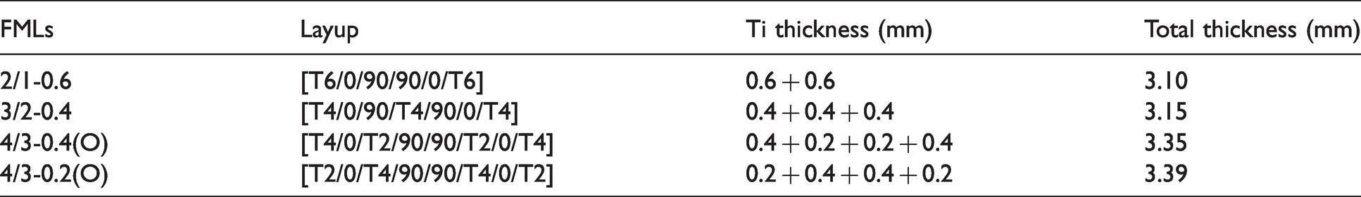
To fabricate FML 2/1-0.6, cutting off two titanium sheets of 0.6 mm thickness and four layers of fiber are performed into parts of size 230 × 230 mm2. Nitrocellulose (N. C) thinner D-13 X from Sheenlac is used to clean the surfaces of titanium sheets and good bonding of titanium sheets with epoxy resin is obtained by uniformly roughening on one side of these sheets using an abrasive sheet with a grit size of 80. Following the roughening, thinner is used to clean the sheets which are then dried. A titanium sheet with a roughened surface facing up is placed on a Mylar sheet, which is laid on a flat plate of steel positioning on the bottom of the compression molding machine. Epoxy with its thin layer is smeared on the Ti sheet using a roller operating by hand. A sheet of UD glass fiber with its one layer having an orientation of 0° is placed over this titanium sheet. The fibers are then wetted by smearing a thin epoxy resin layer. The excess epoxy is removed using a steel roller that also breaks air bubbles. Afterward, the placement of another fiber layer with the orientation of fiber set at 90° to the first layer of fiber, followed by applying the resin, is performed. All leftover laminae of composite and layers of titanium follow the replication of this procedure. Eventually, the whole stack is having another Mylar sheet placed over it and a hand-operated roller is used to squeeze the complete assembly, which leads to spreading the resin all over and also eliminating any extra epoxy. The stack with its four corners is having the placement of four spacers of 3.00 mm thickness each and the laminate is having a top steel plate of a compression molding machine of 7 kg weight placed over it. The curing is then applied to this assembly for 4 h to ensure complete cross-linking under the pressure and temperature of 20 bar and 80 °C in a compression molding machine. Laminate is removed following curing and trimming of edges is performed. Similarly, the preparation of FMLs with other layup sequences such as 3/2-0.4, 4/3-0.4(O), and 4/3-0.2(O) is also executed. Sharma et al. 44 indicate details about the nomenclature of FMLs 2/1-0.6, 3/2-0.4, 4/3-0.4(O), and 4/3-0.2(O), i.e., first, second, next numbers and the letters if any. The FMLs with their schematic presentation are shown in Figure 1(a). The six different places are used to measure the thickness of the laminate, which is averaged for FML layups as stated in Table 1. Burn test provides the fiber volume fraction of the composite laminate, which is obtained as about 50%. ASTM D2584 has reported more information. 45 Figure 1(b) shows a typical geometry of specimen used for SHTB testing. 35 The composite laminates are also prepared for testing under a high strain rate. Sheets with larger sizes are considered to cut titanium sheets, composite laminates, and FMLs using a water jet cutting machine and diamond slicing saw. The absence of damages such as cracks or delamination of the edge is ensured by visually examining the samples’ edges following cutting. Samples with flaws are not considered for testing.
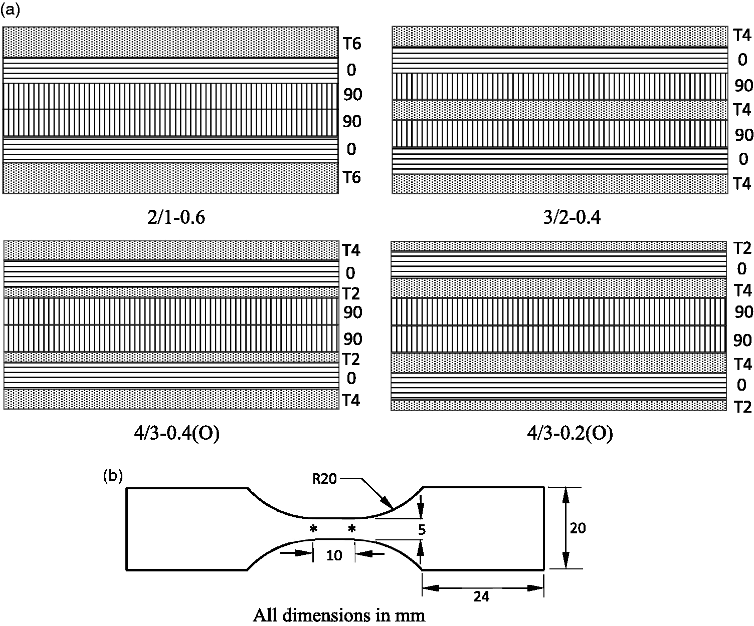
(a) Schematic illustration of FMLs and (b) geometry of specimen used with high strain rate testing.
High strain rate and quasi-static testing under tension
SHTB apparatus of reverse impact type, designed and fabricated in-house, is used to perform high strain rate tests in tension on FMLs constituents such as titanium sheets and GFRP laminates. The schematic illustration of the same is presented in Figure 2(a). An apparatus comprises of incident and transmitter bars, which are two long slender bars with strain gages adhesively bonding on them to record the stress waves, a striker tube, a hollow tube, and a pulse inverter. A stress wave of compressive nature is produced in the inverter by impacting the striker tube on the pulse inverter. A tensile wave is generated as a reflection of this wave from the inverter’s free surface and reached to the specimen and deforming it after traveling through the incident bar and then transmits to the transmitter bar. The pulse inverter and the hollow tube are having a pre-defined gap maintained between them as shown in Figure 2(a). Once closing of this gap happens owing to impact, the hollow tube will have the coupling of the compressive pulse into it, which will get stuck in this tube, thereby, generating the preferred duration of the incident pulse. Sharma et al. 35 report more particulars of the SHTB set up along with the procedure to calculate stress, strain, and strain rate. The sample is connected to the bars using grips as shown in Figure 2(a). The incident and transmitter bars are connected by the threaded portion of the grips whose slot is wider than the specimen thickness to be tested as shown in Figure 2(b). Bonding of the specimen to the grips is performed using adhesive as can be seen in Figure 2(c). Titanium sheets and GFRP laminates are tested using grips with dissimilar slot size. The deformation on the gage region, which has a pattern of random intensity, is measured using DIC. For this, the optical images are recorded using a Photron SA1.1 high-speed camera with a frame rate, time of exposure, and image resolution of 1,00,000 frames per second, 1 microsecond, and 320 × 128 pixels with a suitable source of light. Figure 3 presents the photographic set up of the experiment. The images are correlated and histories of displacement and strain are extracted by post-processing the images later using the commercial software Vic-2D, provided by Correlated Solutions Inc., USA. The step and subset sizes of 5 pixels and 21 x 21 pixels 2 have been used with the calculation of strain. The reflections of stress waves occur within the assembly of the grip-specimen owing to the grips and the layer of adhesive. Thus, using waves of the incident, reflected, and transmitter to establish a specimen with the equilibrium of stress could not be possible. Despite this, the comparison of local strains with their histories of time at the two points indicated in Figure 1(b) extracting from data of DIC is executed to investigate whether the deformation of homogenous nature occurred or not. In the case of quasi-static tests on FMLs and their constituents, displacement controlled loading frames of Kalpak and Shimadzu machines with capacities of 20 kN and 50 kN are used at a cross-head rate of 1 mm/min at room temperature as reported in Sharma and Velmurugan. 43 Consistent and reliable data reportedly provided by a specimen of dog-bone-shaped geometry with gauge length and width of 60 mm and 10 mm are used.37,42,43,46 The engineering strain is obtained from the displacement, which is measured using the DIC technique. More details can be found in Sharma and Velmurugan. 43 The response of FMLs under high strain rate loading will be predicted in the subsequent section.
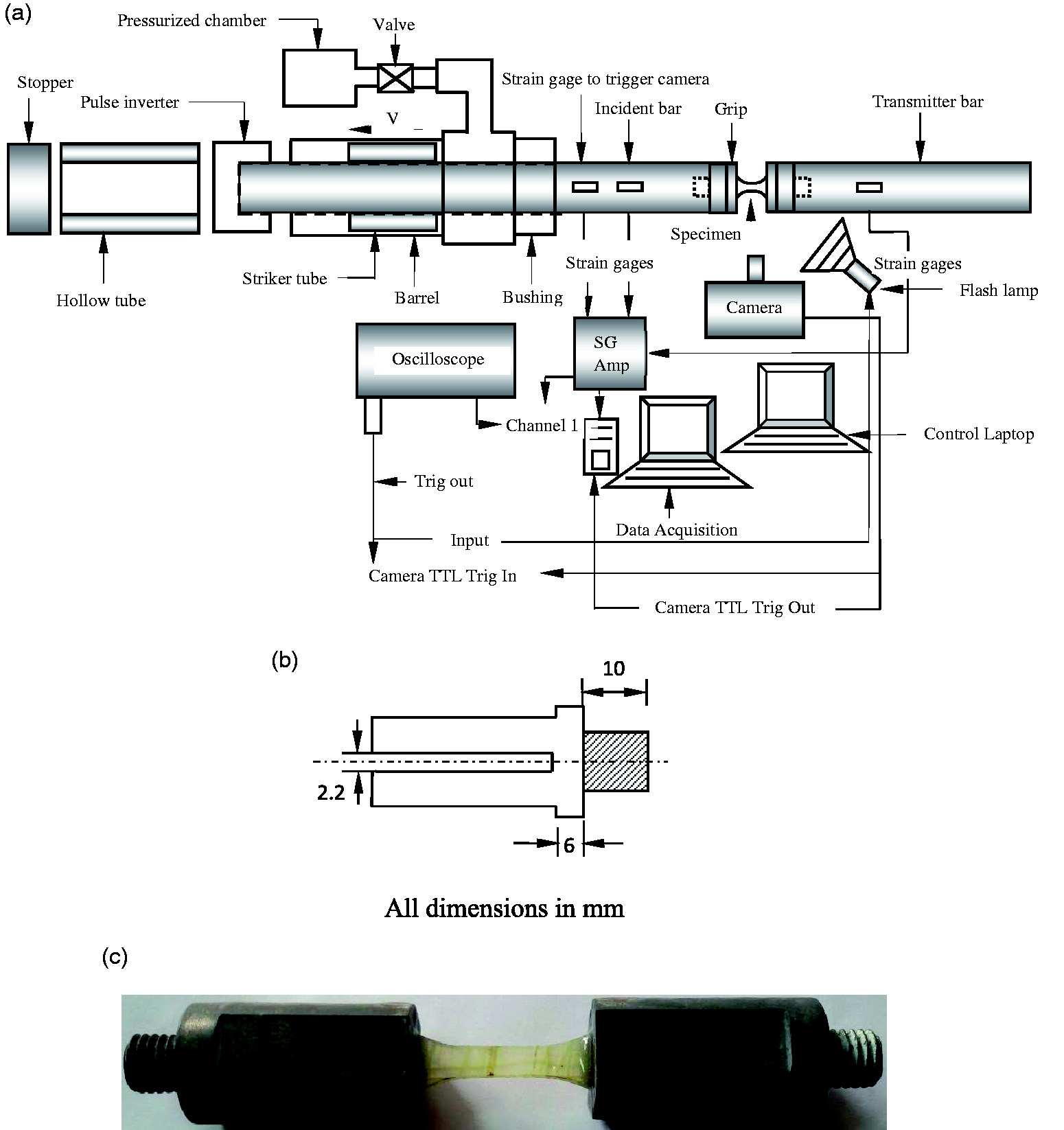
(a) Schematic diagram of the tensile split Hopkinson pressure bar setup, (b) grip geometry, and (c) bonding of composite to grips.
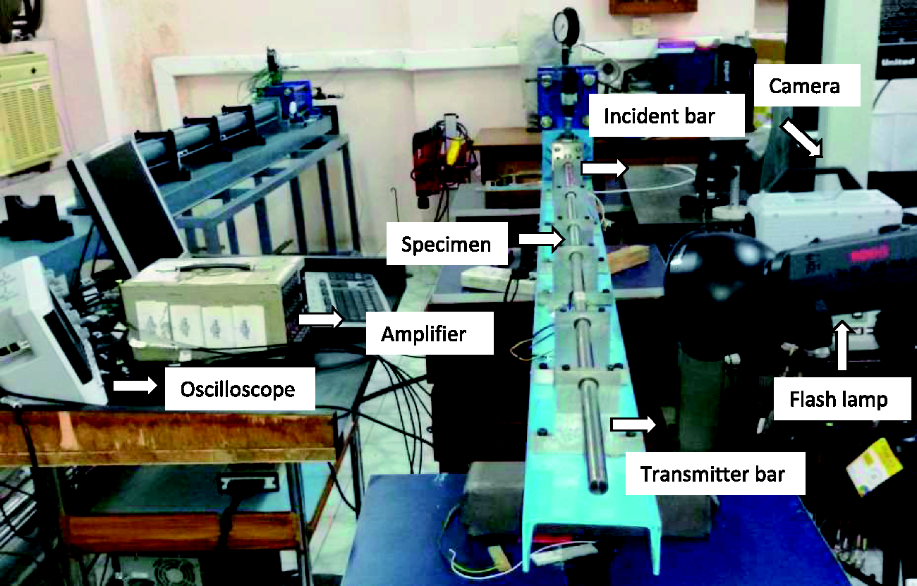
Photographic setup of the experiment.
Analytical modeling
An orthotropic plasticity model
The composite consisting of boron/aluminium constituents with its plastic behavior under a state of in-plane stress is designated by Kenaga et al.
47
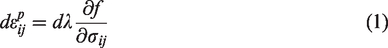
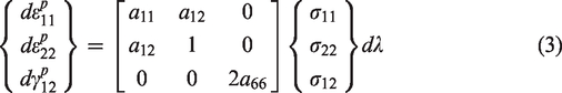
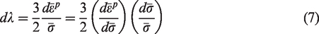
using an orthotropic plasticity model (OPM) entailing three parameters. The plastic strain with their increments is given by the flow rule of plasticity as follows


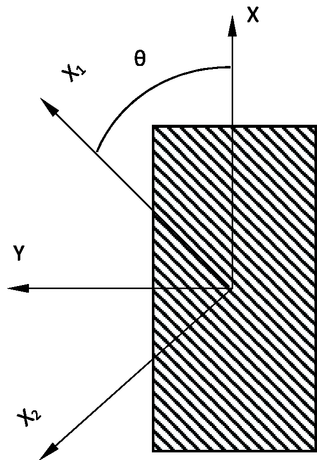
Coordinate systems with their definitions.
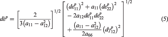
The increment of plastic work can be given by

Thus,
The stress-strain relation under a plastic state with its increment is completed by forming a correlation between 
The stress components concerning the material, whose axes are principal 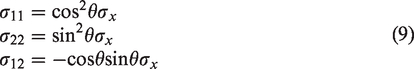
Equivalent coordinate transformation for strains and equations (1) to (5) are used to obtain the relations given as following:

where the plastic strain obvious along the 
Therefore, the preferred correlation 

The Poisson’s ratio being plastic is defined as

For 
Laminated plate model
The basis of the properties known for laminae is being considered for the classical laminated plate theory behind its development. A constitutive model for glass/epoxy and titanium described below is comprised of this theory.
Glass/epoxy model
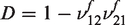
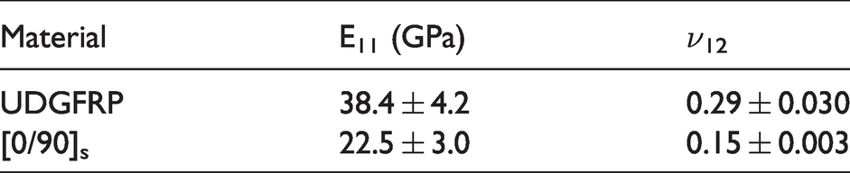
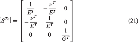
The lamina of glass/epoxy is supposed to be a solid of linearly orthotropic nature and elastic type. The stress-strain relations of incremental type is


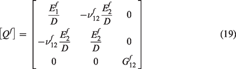
Superscript
Elastic properties of composite laminate with a unidirectional layup.
Constitutive model for titanium
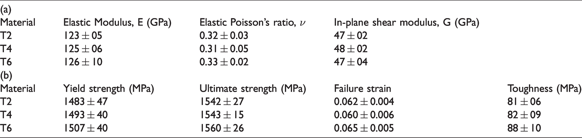
The titanium lamina is modeled considering a solid with orthotropic nature and elastic-plastic type as described in the ‘An orthotropic plasticity model’ section. Therefore, two models are to be necessarily used for titanium alloy. The models of the first and second type display deformations with elastic and plastic behavior, respectively. The titanium deformation with elastic part is given by


Properties of titanium Ti-6Al-4V sheets.
As a result,

The incremental plastic strain and stress are connected as

The relations of nominal stress-strain of incremental form for titanium are given by

in which,

Equation (27) is inverted to produce


The consideration of isotropic plastic material is approximately made for titanium, implying similar plastic Poisson’s ratio along with directions of 0°, 45°, and 90°.
Laminated plate model
The classical theory for the laminated plate is developed by using the basis of constant strain assumption for in-plane strains as follows


Using stress-strain relations of incremental type for layers of both constituent, we acquire


In the equation given overhead,

Note that
Results
The tensile response and failure patterns of the FMLs obtained from experiments and analytical modeling, for high strain rate loading, are presented in this section. In this case, the stress-strain curves of FMLs with the elastic region are obtained by LPM using equation (32). The yield strength of FMLs is estimated by the rule of mixture (ROM), given by equation (7) of Sharma and Velmurugan. 42 Following the yielding of titanium layers within FMLs, equation (33) of LPM is used to produce stress-strain curves of FMLs with the plastic region. In this case, the ‘Constitutive model for titanium’ section describing the Ti-6Al-4V titanium sheet with the development of the plasticity model, which approximately considers it as a plastic material of isotropic nature. Ti sheet and glass/epoxy laminate with their elastic-plastic model (equation (29)) and a linear elastic model up to the fracture point (equation (16)) are correspondingly entailed by this model. The results obtained from this model will be plotted up to maximum stress. The successive behavior of FMLs is assumed to exhibit degradation of stress with increasing strain till achieving failure of composites. This is followed by the behavior of plastic deformation of titanium sheets until achieving failure. The schematic representation of damage progression within titanium-based FMLs at various instants of time is obtained by considering the behavior of corresponding stress and strain history. Further, the corresponding damage progression within aluminium-based FMLs as presented in Figures 8, 11, 14, and 17 of Sharma et al. 35 is considered. This is because the kind of damages, particularly the damage of GFRP within titanium-based FMLs believes to be similar to aluminium-based FMLs. The elastic modulus, strength, strain at maximum stress, failure of composites and FMLs, and toughness for four layups of FMLs will be estimated. Apart from this, the validation of the proposed models is executed by associating them with the corresponding experiments of aluminium-based FMLs, reported in Sharma et al. 35
Titanium sheets
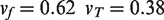
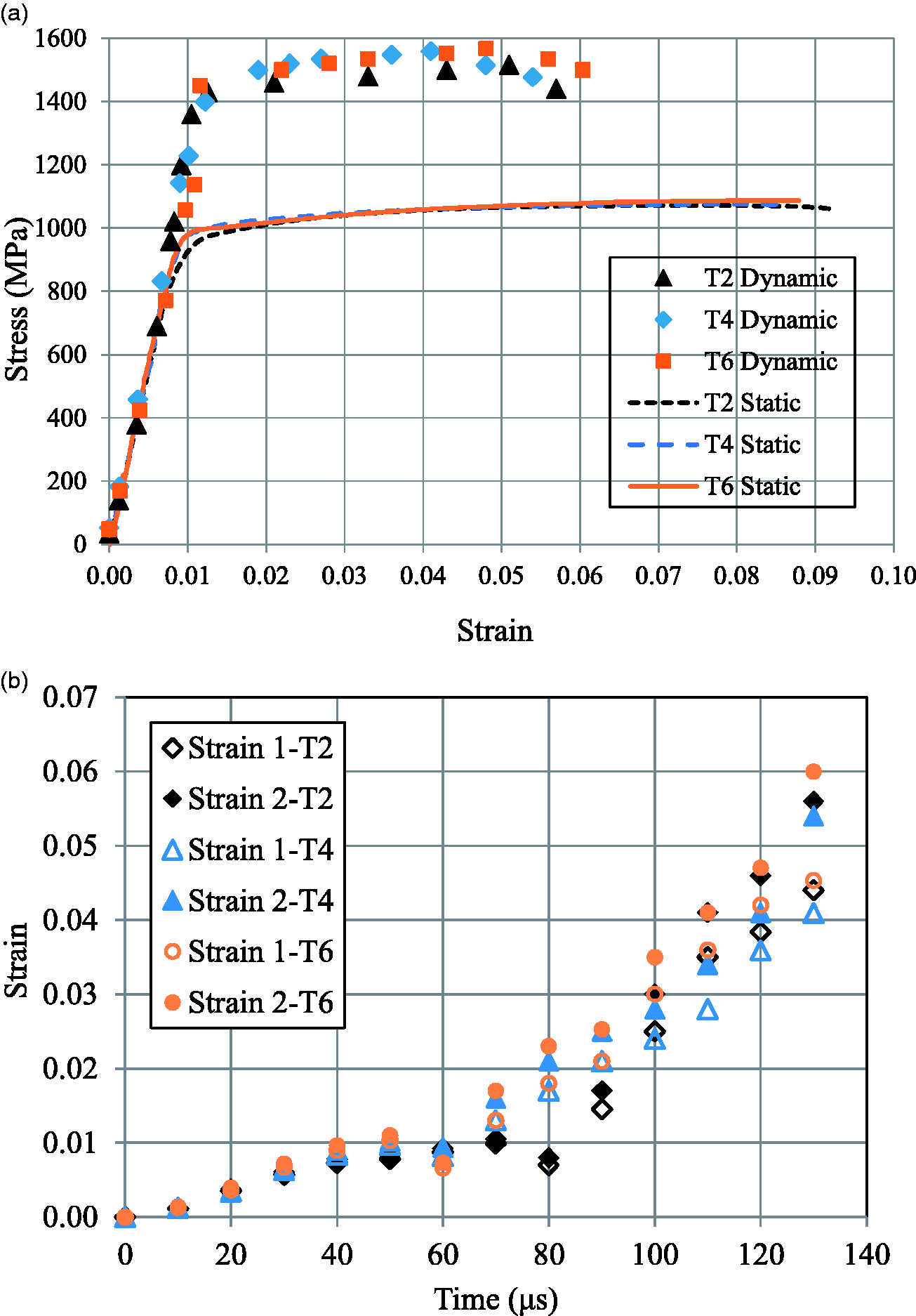
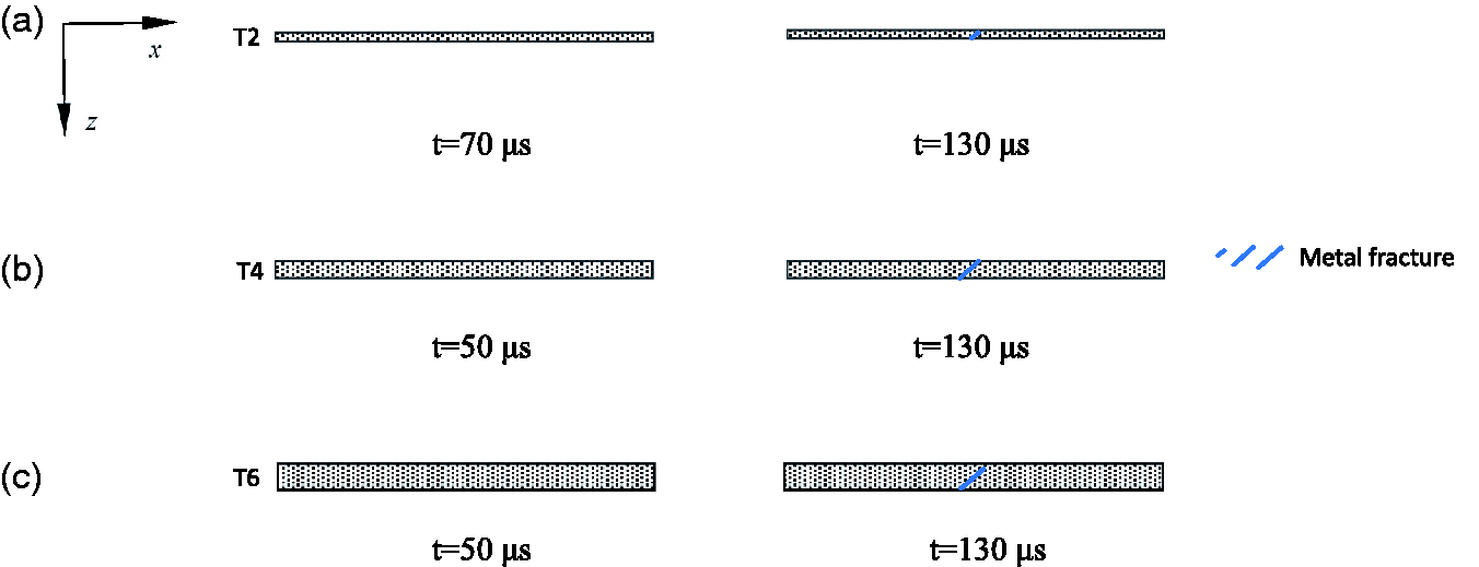
The stress-strain curves for Ti-6Al-4V sheets with thicknesses of 0.2 mm, 0.4 mm, and 0.6 mm, which are used to manufacture FMLs, are shown in Figure 5(a) under a high strain rate of 900/s, 600/s, and 700/s, respectively along with quasi-static strain rate. The curves seem to coincide more or less. The properties measured for titanium sheets are listed in Table 3. Measurements precision cause alterations in the table. It is observed that the stress-strain response shows an apparent increase with the elastic modulus, yield strength, ultimate strength, and decrease with the failure strain with an increasing strain rate of about 700/s over the quasi-static rate of strain. Similar observations are also reported in the literature.16–18 It is to be noted that the variation of a strain of titanium sheets measured from DIC is within 8% of the strain up to the strain level of 0.0099 (t = 70 μs), 0.0096 (t = 50 μs), 0.0103 (t = 50 μs) for T2, T4 and T6, respectively, as can be seen in Figure 5(b). This figure labels Strain 1 and Strain 2 indicating values of local strain at the two points as shown in Figure 1(b). This specifies that the deformations of near homogenous nature are experienced by titanium sheets up to the aforementioned times followed by non-homogeneous deformations till failure. The schematic diagram showing evolution of damage for titanium alloy sheets is given in Figure 6. The specimens do not seem to exhibit damage during the elastic deformation up to 70 μs, 50 μs, and 50 μs for T2, T4, and T6, respectively. This is continued with thinning, necking, and shear fracture during the plastic deformation of titanium sheets up to 130 μs. The stress-strain curves of titanium sheets predicted by equations (20) and (25) up to the failure of composites within FMLs are shown in Figure 7 and are found to be in good agreement with experiments.
Ti-6Al-4V alloy sheets with thicknesses of 0.2 mm (T2), 0.4 mm (T4), and 0.6 mm (T6) (a) Stress versus strain up to failure and (b) strain variation across the specimens.
Schematic diagram showing damage evolution of titanium alloy sheets (a) T2 (b) T4 and (c) T6.
Stress versus strain for titanium alloy sheets up to nearby the failure of composites within FMLs.
Composite laminates
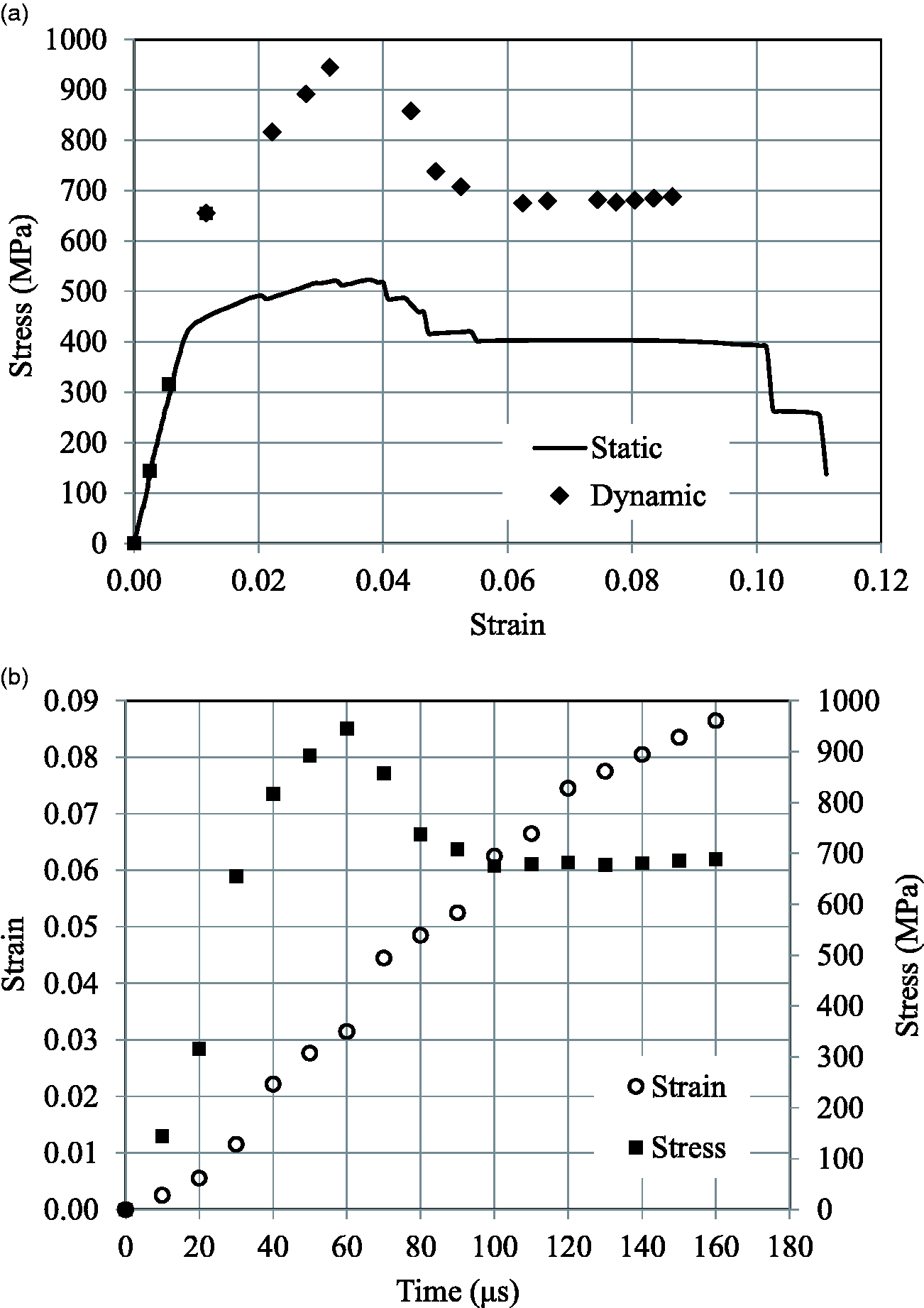
Figure 8(a) presents a typical stress-strain plot for 0° laminate at a nominal strain rate of 500/s along with a quasi-static rate, with strain acquired from DIC. 0° laminate shows a linear elastic behavior up to the level of maximum stress. The strain variation of the specimen at two points shown in Figure 1(b) measured from DIC is within 10% of the strain up to the level of the strain of 0.019 (t = 40 μs) as can be seen in Figure 8(b). This indicates near homogenous deformation experiencing by 0° laminate up to the aforesaid time. The schematic diagram of damage evolution of specimen at various instants of time during loading is shown in Figure 8(c). At t = 30 μs, the specimen does not develop any visible damage. Consecutively, at 40 μs, minor damage of fiber, which is localized within the gage length nearby the bottom edge of the specimen at a strain level of 0.021 and stress of 801 MPa, is observed. At 80 μs, damage of fiber seems widely at the bottom edge corresponding to a strain level of 0.024 and stress level close to 911 MPa. Dropping of stress starts following a strain level of about 0.025. This corresponds to 90 μs at which damages of fiber occur broadly on both edges of the specimen. The failure is dominated by fiber, exhibiting longitudinal splitting. The measured strength on averaging is 988 ± 46 MPa, which is higher by about 51% to quasi-static strength. Shokrieh and Omidi 12 have reported the trend for laminates of UD glass-epoxy, which is in agreement with the present study. Tests are also performed on [0/90]s glass-epoxy laminate, exhibiting typical stress-strain response at dynamic (400/s) and quasi-static conditions as shown in Figure 9(a). There is a perceivable change in the slope of the stress-strain response at a high strain rate. The specimen with its variation of strain at two points denoted in Figure 1(b) measured from DIC is within 9% of the strain up to the strain level of 0.026 (t = 50 μs) as shown in Figure 9(b). This designates the deformation of near homogenous nature experiencing by the specimen up to the preceding time. The schematic drawing of the specimen with damage development at various instants of time during loading is displayed in Figure 9(c). At 20 μs, damage does not visible within the laminate. At 30 μs, the elastic deformation sustains with the formation of matrix cracks within 90° layers. At 40 μs, more matrix cracks emerge. In succession, at 50 μs, minor fiber damage nucleates within 0° layers at a strain of 0.024. At 70 μs, the damage progresses to excessive levels within 0° layers upon the strain of 0.031 before initiating the dropping of stress. The average strength recorded at a high strain rate is 723 ± 84 MPa, which is more than twice the strength under the quasi-static rate. 0° laminate shows the elastic properties of a higher degree than cross-ply laminate.
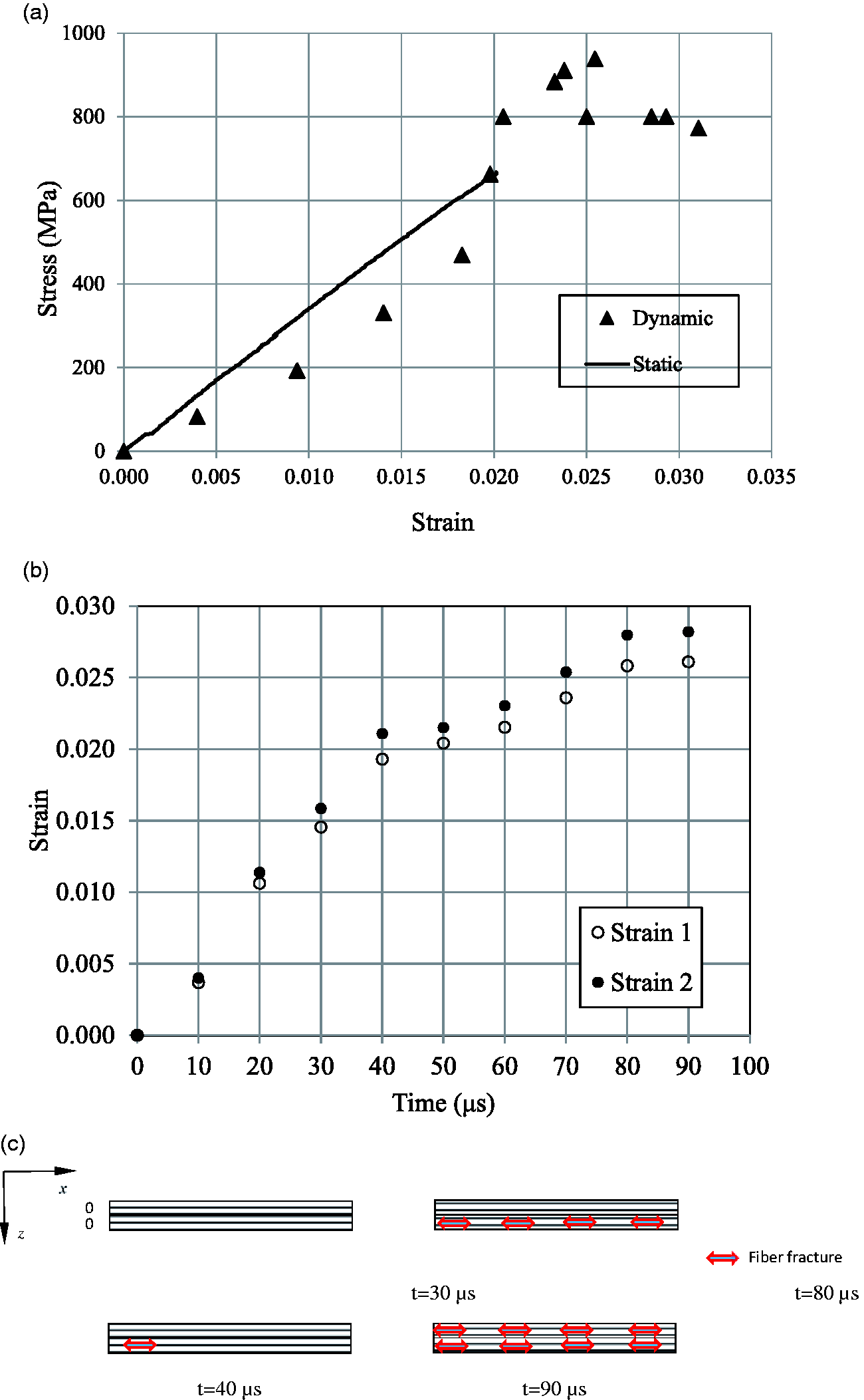
0° laminate (a) Stress against strain, (b) strain variation across the specimen, and (c) schematic illustration showing the progression of damage at various time instants.
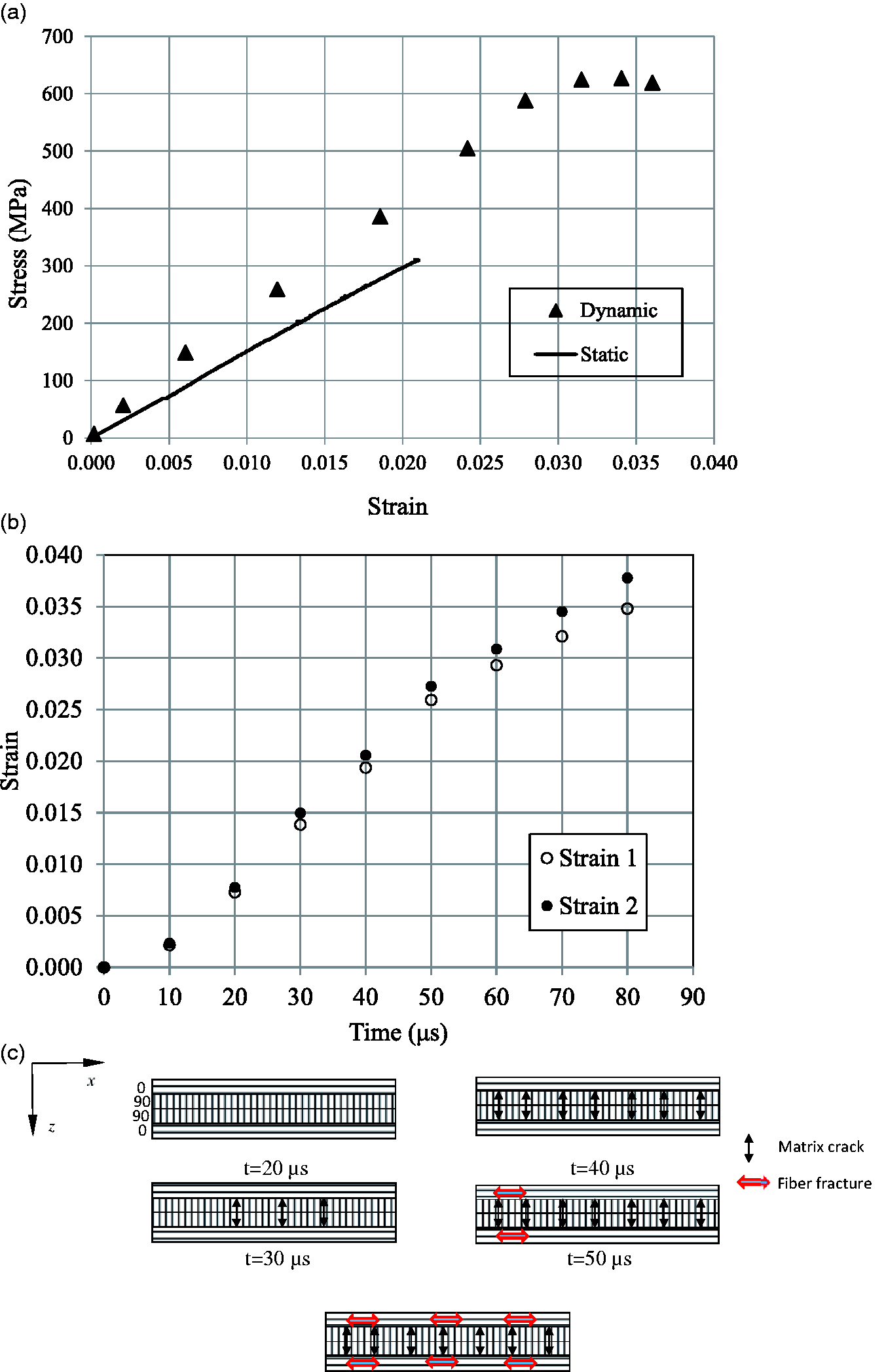
[0/90]s laminate (a) Stress against strain, (b) strain variation across the specimen, and (c) schematic drawing screening growth of damage at various instants of time.
FML 2/1-0.6
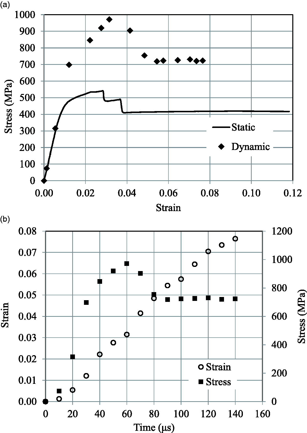
Figure 10(a) presents the analytical stress-strain response of FML 2/1-0.6 by LPM which is typical under a high strain rate. This figure also includes a corresponding response with quasi-static loading. The stress-strain behavior is having a slope change that can be detected close to levels of stress of 763 MPa and 430 MPa at high and quasi-static strain rates, representing the yielding of titanium layers within FMLs. Away from this point, a gradual decrease is noted for the slope of the curve until the maximum stress is attained in both cases, which are 980 MPa and 547 MPa, respectively for high and quasi-static strain rates. The corresponding failure strain of composites within FMLs is found to be 0.031 and 0.027. The dipping of stress happens following peak stress as the failure of composite layers initiates. Static loading is having a sudden dip in the stress. The layers of titanium carry the whole load following the layers of composite with their complete failure as for quasi-static loading.
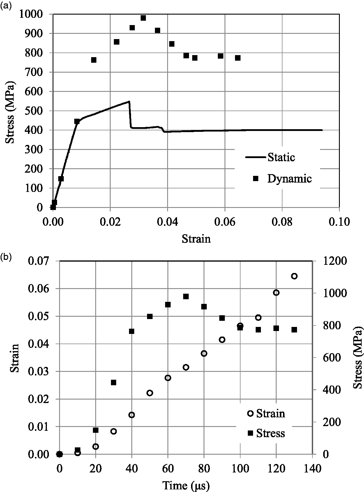
FML 2/1-0.6 (a) Stress against strain and (b) history of stress and strain under dynamic loading.
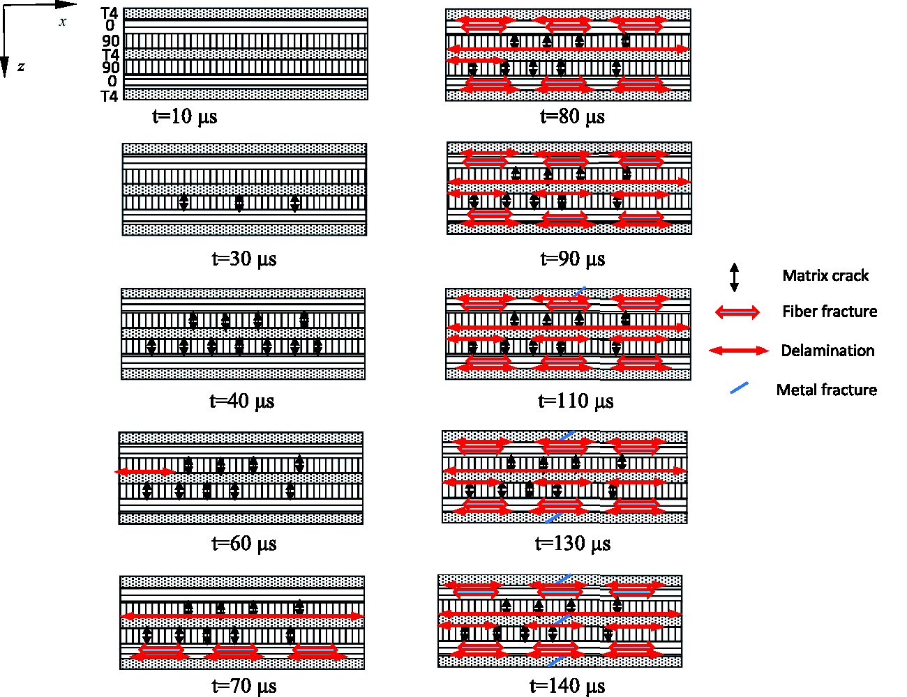
Figure 10(b) shows histories of stress and strain which is representative, with timing between two frames as 10 μs as in the case of constituents of FMLs. Using this, the strain rate is around 500/s until the maximum stress of FML and decreases following the failure of composites within FML till the failure of titanium layers. The schematic photograph of the specimen displaying advancement of damage to occur at various instants of time is presented in Figure 11. Using this, at 10 μs, the specimen does not exhibit any visible damage. Following the yielding of titanium layers, at 40 μs, layers of 90° exhibit the initiation of cracks. At 50 μs, more matrix cracks emerge. Successively, at 60 and 70 μs, less and more damage of fiber within one and both layers of 0° occur. Subsequently, another event with more damage of 0°fiber layers to occur at 80 μs, resulting in initiation with the dipping of stress. At 90 μs, the delamination between titanium and composite layers happens. Successively, at 100 μs, the gage region experiences initiation of localization of strain. Figure 10(b) is having an overall strain of 0.046 at this time of 100 μs and the level of stress is more than quasi-static stress. This specifies that the load is being carried by the rate-sensitive layers of titanium till failure at 130 μs. The quasi-static loading is having the stress-strain response, which is analogous in trend to dynamic loading, while, the dropping of stress is steeper following maximum stress. The loading continues with plastic deformation of titanium sheets till failure.
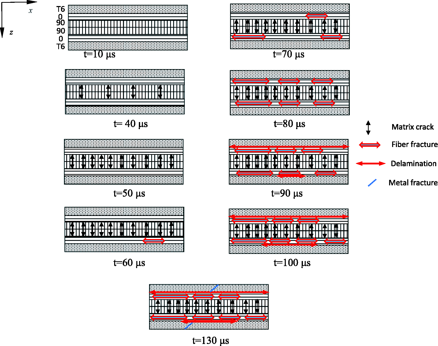
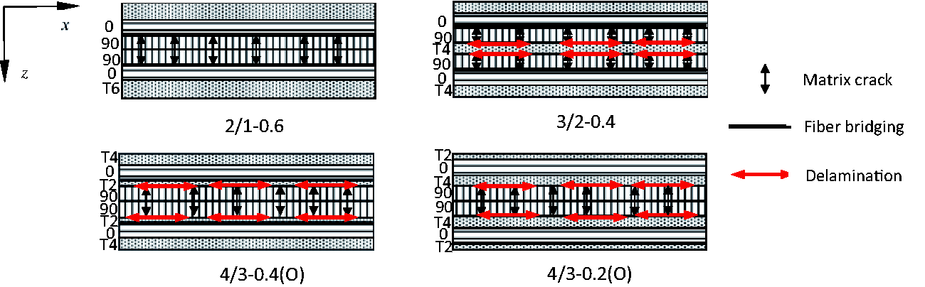
Schematic illustration presenting the evolution of damage to occur at different moments for FML 2/1-0.6.
FML 3/2-0.4
Figure 12(a) presents the analytical stress-strain response of FML 3/2-0.4 by LPM, which is typical under high strain rate and quasi-static loadings, and Figure 12(b) presents corresponding histories of stress and strain. The response of Figure 12(a) until the failure of composites within FML is similar to FML 2/1-0.6 under dynamic loading. Linear increment of stress is observed with strain initially and following the level of stress of 699 MPa, a continuous decrease of slope starts until the ultimate stress. Afterward, the decrease in stress is noted with increasing strain until it reaches 0.054. However, the degradation of stress seems progressive following the maximum stress when compared to FML 2/1-0.6. This is followed by the plastic deformation of titanium sheets which are rate-dependent, carrying the bulk of the load and exhibiting a stress level that seems more than quasi-static stress until failure. It is to be noted that the strain rate obtained from the history of strain showing in Figure 12(b) is 600/s until maximum stress and decreases following composites failure till failure of titanium layers. The schematic diagram depicting the progression of damage to be emerging at numerous times within the laminate is presented in Figure 13. From this, the specimen does not exhibit damage at 10 μs. The deformation continues with matrix cracks emerging in one of the [0/90] laminates as early as 30 μs, which corresponds to the stress level of around 699 MPa. The next image equivalent to 40 μs exhibits matrix cracks within another [0/90] laminate. At 60 μs, delamination initiates between the layers of titanium locating on the middle and the composite above it, resulting in the initiation of dipping of stress as observed in Figure 12(a) and (b). The next image at 70 μs exhibits the delamination growing to the whole gage length and the dipping of stress continues. Also, damage of fiber appears in one of the [0/90] composite layers. This causes nucleation of delamination between the lower titanium sheet and adjacent 0° composite layer along the gauge length. At 80 μs, delamination initiates between the middle titanium layer and composite layer locating below it, causing damage of fiber within another layer of [0/90] composite. The [0/90] laminate locating on the top exhibits damage, which increases with loading. This causes delamination between the top titanium sheet and adjacent 0° layer of composite. Consecutively, the extent of delamination between the middle titanium sheet and 90° layer locating below it increases along the gauge length at 90 μs. Following this, the plastic deformation continues with more load started to share by the layers of titanium, and initiation with localization of strain happens. Initiation of cracking observes on the top layer of titanium at 110 μs and stress of around 727 MPa. The crack on edge of the specimen locating on the opposite side would appear at 130 μs. The eventual failure of the remaining titanium layer and therefore FML would result at 140 μs which is higher than FML 2/1-0.6. The composite layers are relieved for some time with a drop in stress by initial delamination in this case. Individual layers would be having increased levels of stress with sustained deformation, resulting in damage which would be additional, but not of a form that seems disastrous for FML 2/1-0.6. This is the basis for the case of FML 3/2-0.4, where the significant falling of stress has not happened. The progressive failure is also exhibited by the stress-strain response of FML 3/2-0.4 after peak stress under quasi-static loading. This is followed by the deformation up to the failure of titanium layers.
FML 3/2-0.4 (a) Stress against strain and (b) history of stress and strain under high strain rate loading.
Schematic diagram displaying the progression of damage to ensue at various instants of time for FML 3/2-0.4.
FML 4/3-0.4(O)
A characteristic analytical stress-strain response of FML 4/3-0.4(O) by LPM is presented in Figure 14(a) for high strain rate loading along with quasi-static loading and the histories of stress and strain are shown in Figure 14(b). Once the stress reaches around 662 MPa, a clear slope change can be detected. Following this, a dissimilar slope of the curve has been noted and noticeable change is not apparent with this slope until ultimate stress. Afterward, the dropping of stress is observed at 882 MPa, for which strain is 0.044. Consequently, successive reduction in stress with gradually increasing strain becomes apparent. This is followed by the plastic deformation of titanium sheets which are rate-dependent, carrying the majority of the load and exhibiting more stress than quasi-static stress till failure. It is noticed from strain history presented in Figure 14(b) that the strain rate is 700/s up to ultimate stress, following which it reduces till cracking of titanium layers.
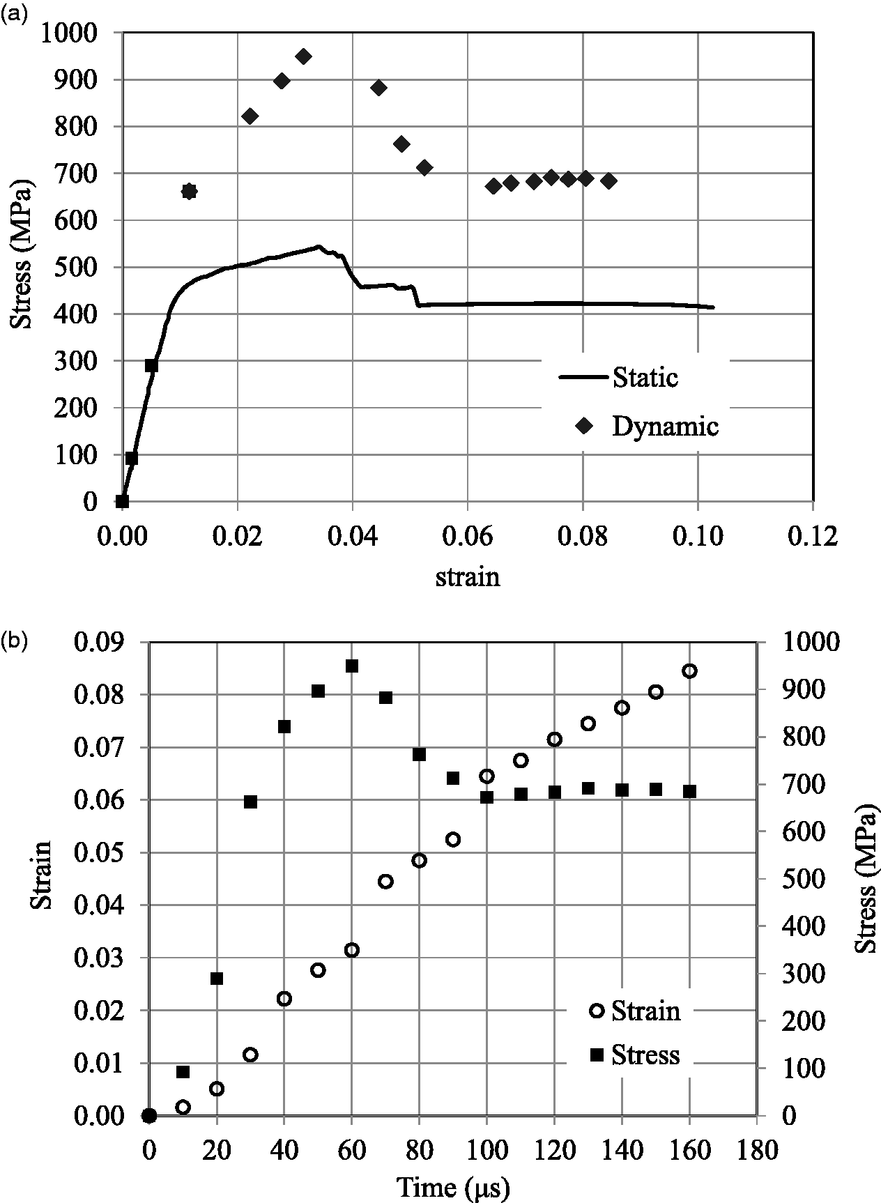
FML 4/3-0.4(O) (a) Stress against strain and (b) history of stress and strain under high strain rate loading.
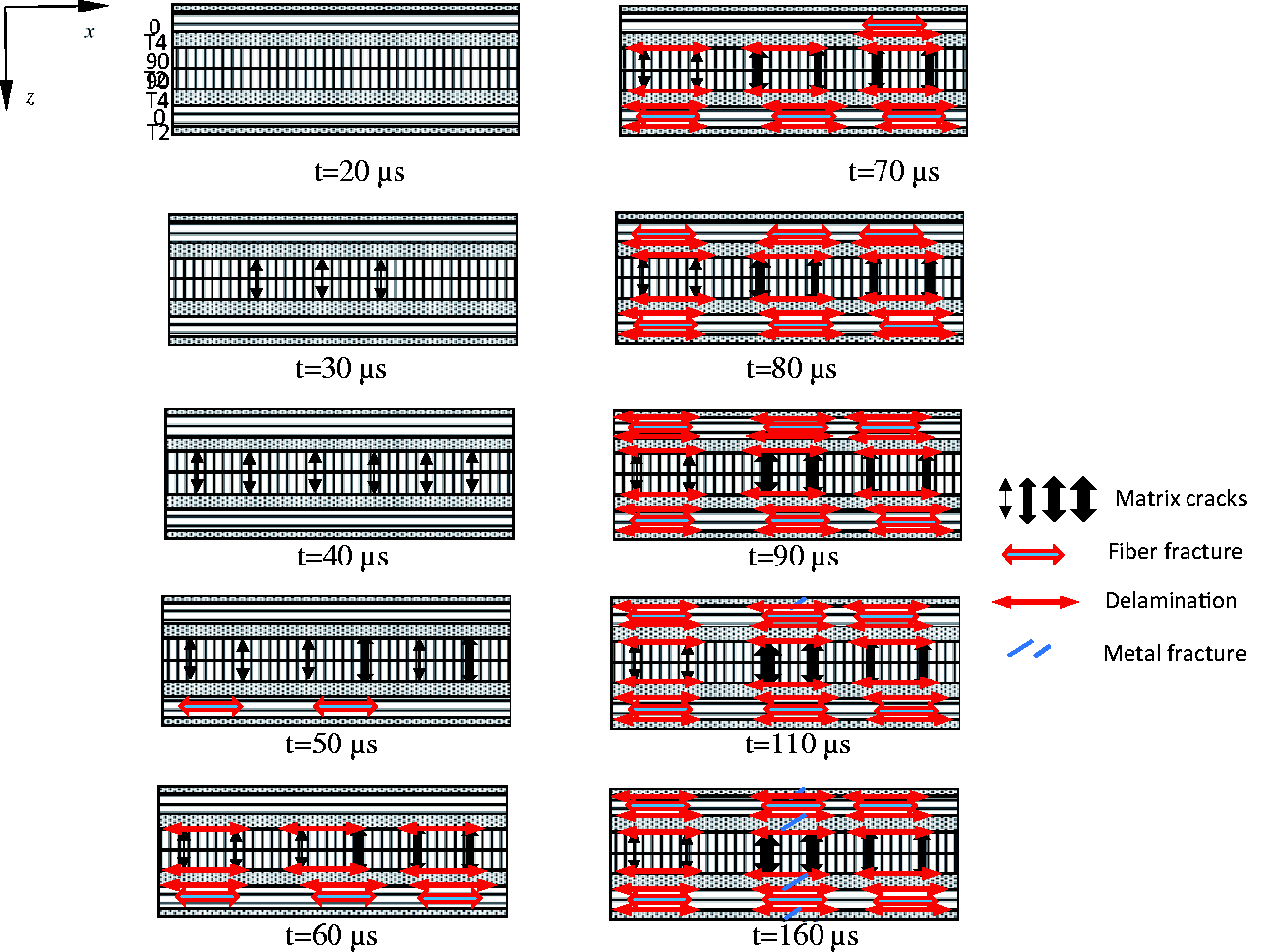
The schematic diagram displaying the sequential growth of damage to occur at several moments for the laminate is shown in Figure 15. The specimen does not exhibit any visible damage at 20 μs. Following this, middle [90]2 layers would develop cracks at 30 μs, which is equivalent to a level of stress of 662 MPa. [90]2 layers exhibit increasing numbers of cracks with deformation, which are also opening up at 40 μs, exhibiting one of the cracks with comparatively bigger size than others. This continues with more number of bigger size cracks for 90° layers, i.e., the opening of cracks, with one of the 0° layers to exhibit damage at 60 μs, which corresponds to ultimate stress as can be seen in Figure 14(b). The stress falls once the breaking of this 0° layer initiates, but the fall of steep form is not noticed as the load can still be transmitted by another 0° and titanium layers. The layers of middle [90]2 and titanium sheets placing on either side display the commencement of delamination at 70 μs. The damage developing within one layer of 0° at 60 μs causes delamination to nucleate between this 0° layer and adjacent T2 sheet. In addition to this, at 70 μs, the development of damage of fiber within the second layer of 0° happens, causing the corresponding delamination between this 0° layer and the adjacent T2 sheet. A layer of [90]2 with some of the cracks appears to be closed, which are equivalent to images of 80 μs and 90 μs, owing to pieces of fracture with comparative sliding between them, exhibiting some cracks of 90° layers with a bigger size. This is followed by the top and bottom layers of T4 sheets with delamination between them and adjacent 0° layers at 80 μs. Fascinatingly, the top T4 layer undergoing flexure, which is out-of-plane following delamination, observes at 90 μs. The initiation of localization of strain within the region of gage area to happen for the top T4 layer at 100 μs. This to continue till the failure of titanium layers within FML at 160 μs. The latter time is observed to be higher than FML 3/2-0.4. A bilinear kind of response is also exhibited by quasi-static loading with a stress-strain response before the ultimate stress, followed by a failure of gradual form for composites. The deformation sustains till the failure of titanium layers.
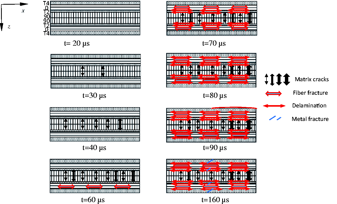
Schematic diagram demonstrating the sequential progression of damage to take place at various instants of time for FML 4/3-0.4(O).
FML 4/3-0.2(O)
In this FML, the thinner layers of titanium are considered as the outer layers compared to thicker layers for FML 4/3-0.4(O). Figure 16(a) presents a typical analytical stress-strain response of FML 4/3-0.2(O) by LPM under high strain rate and quasi-static loadings. Figure 16(b) depicts the equivalent histories of stress and strain. The level of stress of 655 MPa indicates the slope change for the response of stress-strain and afterward, this slope remains realistically constant until ultimate stress. Following this time of 60 μs, the dropping of stress is observed in Figure 16(b) and subsequently, a slight reduction of stress happens continuously with gradually increasing strain till failure of composite layers. Consecutively, the titanium layers, which are still carrying the load, continue to deform plastically till fracture as with quasi-static loading. The strain rate noted from Figure 16(b) is 600/s until maximum stress, following which it diminishes until the failure of titanium layers.
FML 4/3-0.2(O) (a) Stress against strain and (b) history of stress and strain under high strain rate loading.
The schematic diagram illustrating the evolution of damage to happen at several time instants for the laminate is shown in Figure 17. Considering this, at 20 μs, the laminate does not unveil any damage. This progresses with layers of [90]2, exhibiting initiation of matrix cracks at 30 μs. More matrix cracks emerge at 40 μs. The images analogous to 40 μs onwards exhibit damage developed within the 0° layer and bigger size cracks for 90° layers at 50 μs, which continue to rise with rising deformation. This causes delamination between the corresponding 0° and T4 layers at 60 μs. Also, at this time, delamination nucleates between [90]2 and adjacent titanium layers, forming cracks of bigger size for 90° layers. At 70 μs, delamination unveils between layers of one of 0° composites damaging at 60 μs and lower T2 layer. Also, at this time, failure with another 0° composite layer takes place, causing delamination between it and the adjacent T4 layer. The deformation continues with more extent of failure for another 0° layer along with delamination between it and adjacent T4 sheet at 80 μs. This is followed by the corresponding delamination between this 0° layer and another top T2 layer at 90 μs. At 100 μs, the beginning of localization of strain within the section of gage area to ensue for top T2 sheet, and at 110 μs, cracking off one of T2 sheets appears. Successively, the failure of remaining titanium sheets occurs within the gage area of FML till time reaches 160 μs, which is noted to be similar and higher than FMLs 4/3-0.4(O) and 3/2-0.4, respectively. A bi-linear behavior is also exhibited by the quasi-static response of FML 4/3-0.2(O) shown in Figure 16(a) before ultimate stress. This is followed by a gradual drop of stress with increasing strain with deformation to continue till failure of titanium layers.
Schematic diagram presenting the sequential development of damage to occur at different instants of time for FML 4/3-0.2(O).
An orthotropic plasticity model
Effective stress
Effective stress-effective plastic strain for FMLs.
FMLs stress-strain behavior predicted by orthotropic plasticity model and laminate plate model.
Validation of the proposed models
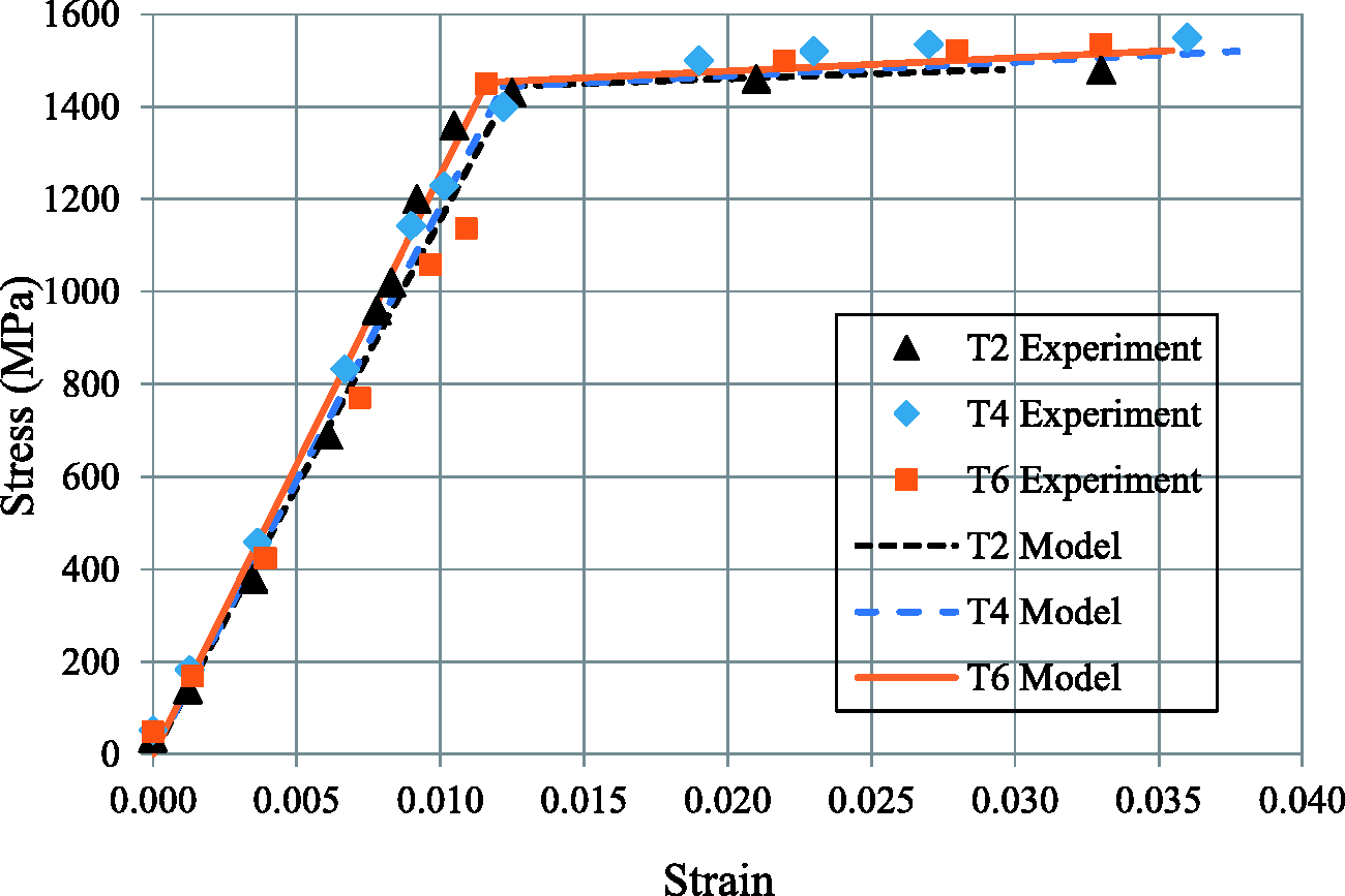
To insist on the robustness of proposed models (laminated plate model and orthotropic plasticity model), the predictions of aluminium-based FMLs up to the maximum level of stress (i.e., close to the failure of composites within FMLs) are compared to the corresponding experiments, reported in Sharma et al. 35 as can be seen in Figure 20. It is to be noted that, overall, the experimental data is fairly well fitted by both models. It can be stated that the models’ predictions with stress-strain behavior having elastic and plastic parts for FMLs are found to be in good agreement with corresponding experimental results. Further, the predicted variations of linear and non-linear types with the behavior of elastic and plastic types of FMLs exhibit slopes of two different types up to levels of the strain of about (0.006-0.008) and (0.008-0.032), individually when compared to experiments. Therefore, the titanium-based FMLs with their predictions up to the maximum level of stress using the aforementioned models as presented in Figures 10(a), 12(a), 14(a), 16(a), and 19 are expected to be found in good agreement if plotted with corresponding experiment results.
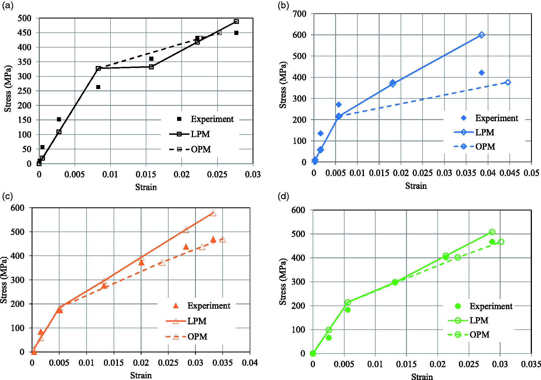
Stress-strain behavior of aluminium-based FMLs with a comparison of experiments with laminated plate model and orthotropic plasticity model. (a) 2/1-0.6 (b) 3/2-0.4 (c) 4/3-0.4(O) (d) 4/3-0.2(O).
Discussion
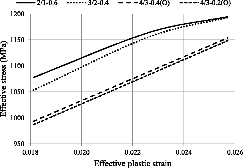
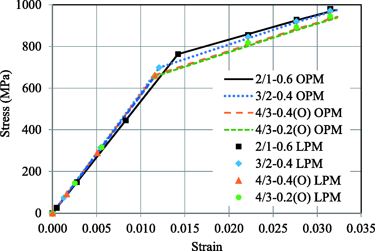
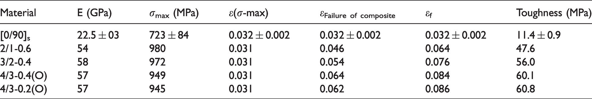
In this section, the comparison of the response of four FMLs will be performed using the prediction offered by LPM. Table 4 provides the properties of FMLs and composite obtained by LPM under a high strain rate. It can be observed that the elastic modulus of FMLs under dynamic loading is (4–16) % higher than quasi-static loading. 43 This is due to the rate sensitivity with the elastic modulus of titanium sheet and composite laminate. It can be observed that a slope change or yield stress occurs for the behavior of stress-strain in the range of stress of around 655-763 MPa for loading with a high strain rate. The behavior of quasi-static also exhibits a slope change around the level of stress of 357-430 MPa. 43 This specifies that the slope change at a high strain rate is (77-83) % higher than the quasi-static strain rate. This is owing to the yield stress of titanium layers, which increases with strain rate, as reported in Figure 5(a). Also, the yield stress of composite, considering equal strain for FML and its constituents and using Hooke’s law for linear elastic behavior of FML, 42 exhibits rate sensitivity. The yielding of the layers of titanium reflects to cause this slope change. The range of stress levels with matrix cracking is observed at (655-856) MPa. The same under quasi-static loading is (220-340) MPa. 43 Therefore, dynamic loading with stress levels of matrix cracking is 2.7-3 times higher than quasi-static stress. Separation of a layer [90]2 from layers of 0° by titanium layers results in cracks with much more opening for FMLs 4/3-0.4(O) and 4/3-0.2(O), exhibiting than FMLs 2/1-0.6 and 3/2-0.4, as reported in Figures 15 and 17. Sandwiching of [90]2 is performed between two layers of 0° for the case of FML 2/1-0.6, while a layer of 90° is placed next to a layer of 0° for the case of FML 3/2-0.4. This causes bridging of matrix cracks by the adjacent layers of 0°fibers, resulting in an opening that is not significant and preventing the complete failure of layers of 90°, which can carry part of the load as observed in Figures 11 and 13. Whereas, the overall stiffness of the layers of 0° is degraded and therefore of FML through the extension of these cracks within 90° layers to the region of a matrix of 0° layers. This results in the behavior of stress-strain of FML whose slope changes continuously, i.e., softening is observed, before ultimate stress, as can be seen in Figures 10(a) and 12(a). It can also be specified that the behavior of slope change, which seems nearly constant, is caused by the mechanical behavior of a single layer of composite along with transverse and shear directions under high strain rate loading. This causes composite laminates to behave non-linearly, exhibiting rate sensitivity, as reported in literature,11,49–52 in addition to the yielding of titanium layers within FML (Figure 5(a)). This behavior for the case of FMLs 2/1-0.6 and 3/2-0.4 obtained by the laminated plate model is well captured by the orthotropic plasticity model up to close to the failure of composites within FMLs, i.e., maximum stress and the strain of 0.031 as noted in Figure 19.
Properties of FMLs and composite.
Further investigation includes that the shielding of layers of 0° from layers of 90° by the layer of titanium does not cause this continuous slope change before ultimate stress. This is for the case of FMLs 4/3-0.4(O) and 4/3-0.2(O), exhibiting nearly a bilinear behavior as observed in Figures 14(a) and 16(a). Therefore, in this case of FMLs, the type of slope with stress-strain behavior up to maximum stress is observed to be different when compared to the other two FMLs. Moreover, FMLs 4/3-0.4(O) and 4/3-0.2(O) response obtained by the laminated plate model is found to be in good agreement with the orthotropic plasticity model up to strain level of 0.031, as can be seen in Figure 19. Loading with a high strain rate exhibits maximum stress, which is around 77-87% higher for all FMLs to loading with quasi-static as tabulated in Table 4,43 exhibiting rate sensitivity. This is believed to be due to the layer of titanium and 0° GFRP laminate, both of them exhibiting ultimate strengths under dynamic loading to be around 45% and 51% higher than quasi-static loading. FMLs are found to exhibit similar ultimate stress for loading with high and quasi-static strain rates. This yields that the ultimate stress of FMLs is not affected by distributing metallic layers.
FML 2/1-0.6 exhibits a drop, which is relatively steep with stress following ultimate stress, indicating a more catastrophic failure for both 0° composites. While in the case of FML 3/2-0.4, this does not occur as [0/90] laminates are isolated by titanium layer. This causes failure of one of [0/90] laminates first with stress is having a reduction. This is followed by the failure of another [0/90] laminate, exhibiting another reduction with stress. Excitingly, FMLs 4/3-0.4(O) and 4/3-0.2(O) exhibit failure, which seems to be more progressive and continuous with 0° layers following maximum stress when compared to FML 3/2-0.4. The separation of matrix cracks in layers of 90° from being extended to layers of 0° is supposed to cause this. This can be clarified by a schematic diagram demonstrating the delamination mechanics between layers of titanium and 0° composite due to matrix cracks developing within 90° layers of FMLs, as presented in Figure 21. This appears to be different for FMLs 3/2-0.4, 4/3-0.4(O), and 4/3-0.2(O) owing to the isolation of composite layers by metallic layers when compared to FML 2/1-0.6. This is responsible for the type of failure for composites embedding within FMLs, i.e. gradual and catastrophic for former three and latter FMLs, respectively as elucidated above. The stress levels of fiber fracture and delamination between titanium and composite layers under dynamic loading are found to be 1.6-2.4 and 1.6-2.1 times higher than quasi-static stress. The titanium-based FMLs with degradation/damage of GFRP within them seems to be analogous to aluminium-based FMLs, reported in Sharma et al. 35 For FMLs, stress levels following the dropping of ultimate stress are found to be higher than quasi-static loading as can be seen in Figures 10(a), 12(a), 14(a), and 16(a). This is supposed to be due to the rate-sensitive behavior of titanium layers as indicated in Figure 5(a). The stress levels of titanium fracture within FMLs under dynamic loading seem to be 1.7-1.9 times higher than quasi-static stress levels as tabulated in (Table 5). In the case of FML 2/1-0.6, the laminate consisting of the entire composite fails in a rather catastrophic nature following the breaking of fibers once initiates, as stated above. Whereas, the loads redistributing locally to the layers of titanium, happen in the case of FMLs 3/2-0.4, 4/3-0.4(O), and 4/3-0.2(O) in which layers of the composite are separated. This causes a gradual drop in stress and failure of composites when they are having increased damage. From this perspective, the damage tolerance of the FMLs is seemed to be improved by using layers of titanium to separate the layers of composite from each other, causing delays of their failure of catastrophic nature. A similar strain rate is obtained until achieving the failure of titanium layers for all cases of FMLs.
Schematic diagram demonstrating delamination mechanics for FMLs.
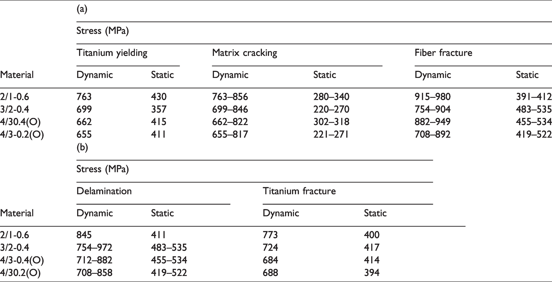
Summary of damage events observed for FMLs during dynamic and static loading.
FMLs of all types with their comparison of stress-strain response predicted by the laminated plate model, maintaining similar metal volume fraction and the total thickness, are presented in Figure 22. The elastic region behavior remains comparable for all FMLs, however, they exhibit variations following titanium layers yielding. This becomes more apparent predominantly away from peak stress during which more progressive failure of composites occurs on adding more layers of metal. This causes FMLs 3/2-0.4, 4/3-0.4(O), and 4/3-0.2(O) to exhibit augmented failure strain when compared to FML 2/1-0.6. It is to be noted that the strain at maximum stress seems similar for all FMLs as of [0/90]s laminate as presented in Table 4. Furthermore, the strain at the entire failure of composites within FMLs 3/2-0.4, 4/3-0.4(O), and 4/3-0.2(O) is found to be enlarged by 17%, 39%, and 35% when compared to FML 2/1-0.6. Also, the fracture strain of GFRP within FMLs is 1.4-2.1 times higher than that of pure [0/90]s laminate. It is to be noted that the FMLs 2/1-0.6, 3/2-0.4, 4/3-0.4(O), and 4/3-0.2(O) with their fracture strain of GFRP constituent under high strain rate is found to be increased by 25%, 41%, 41%, and 35%, respectively, when compared to quasi-static strain rate. This hinders the behavior of GFRP with fiber-splitting and failure, resulting in additional deformation and increased breaking strain and ultimate strength of GFRP within FMLs when compared to pure [0/90]s laminate. These enhancements are believed to be due to the transverse compressive stress on GFRP following yielding of titanium layers resulting from high Poisson’s ratio of titanium sheet when compared to GFRP laminate.
38
Moreover, this improvement also causes FMLs 3/2-0.4, 4/3-0.4(O), and 4/3-0.2(O) with their failure strains to increase by 19%, 31%, and 34% when associated with FML 2/1-0.6, with higher and similar strains are exhibited by both FMLs 4/3. The FMLs failure strains are about 2-3 times higher when compared to [0/90]s laminate. The time to failure seems to be higher for FMLs 4/3-0.4(O) and 4/3-0.2(O) when considering FMLs 3/2-0.4 and 2/1-0.6, which exhibits the lowest time to failure. The summary of failure events occurring sequentially during dynamic and static loading of FMLs is reported in Table 5, exhibiting rate sensitivity as discussed before.
43
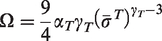
Specifically, the stress at initiation to complete failure of 0°fiber layers and at initiation to widespread delamination between titanium and 0° composite layers for FMLs 2/1-0.6, 3/2-0.4, 4/3-0.4(O), and 4/3-0.2(O) under dynamic loading is found to be 2.35, 1.65, 1.85, 1.70 and 2.10, 1.70, 1.65, 1.65 times higher, respectively, when compared to quasi-static loading. This is supposed to be due to the rate sensitivity of FML constituents, i.e., titanium sheets and composite laminates as shown in Figures 5(a), 8(a), and 9(a). The gage section of FML constituents experiences deformation of near homogenous nature till achieving the time of 50 μs. It is to be noted that the ultimate strength of FMLs seems to be equivalent to that of pure 0° composite laminate. The material’s ability to absorb energy and deform plastically before fracturing is known as toughness, which is evaluated from the stress-strain curve's area as given below
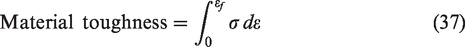
FMLs stress-strain behavior predicted by laminated plate model.
Conclusions
SHTB technique is used to investigate the high strain rate tensile response of FML constituents. In this case, the strains are measured using the DIC technique, and the evolution of damages is tracked using high-speed imaging. Furthermore, the response of FMLs having a dispersion of metallic layers, exhibiting the same metal volume fraction and total thickness, is predicted by the laminated plate model and orthotropic plasticity model up to the level of maximum stress. The subsequent response of FMLs is assumed to degrade with increasing strain till achieving failure of composites. Consequently, the plastic deformation of titanium sheets continues until establishing failure. The damage evolution of FMLs is demonstrated. The dynamic response of titanium-based FMLs is compared with the quasi-static response and aluminium-based FMLs. The validity of the proposed models is performed by comparing them with the experiments of aluminium-based FMLs, reported in the literature. The results of this study indicate the following.
The titanium sheets and 0° GFRP laminate with their ultimate strengths, which are about 45% and 51% greater at a high strain rate to quasi-static strain rate. The rate-sensitive response is also exhibited by FMLs with their ultimate strength enlarged by 77-87% to quasi-static strength. This is primarily believed to be due to the rate-sensitive response of titanium and GFRP. The ultimate strength of FML with the placement of composite layers together is found to be comparable to other FMLs. In contrast, failure of a more catastrophic nature is observed for composites for former FML. The ultimate strength of titanium-based FMLs is 1.7-2.2 times higher than aluminium-based FMLs. Post maximum stress, FMLs with separation of layers of composite by layers of metal demonstrate a failure of more progressive nature for composite layers. FMLs 4/3-0.4(O) and 4/3-0.2(O) exhibit this very prominently. The former separation results in increased damage tolerance of FMLs. The shielding of extension of matrix cracks in layers of 90° to layers of 0° by metallic layer presumes to cause this. The damage events of titanium-based FMLs with their stress levels exhibit rate sensitivity and seem to be higher than aluminium-based FMLs. The rate-sensitive properties such as failure strain of GFRP constituent within FMLs, failure strain and toughness of FMLs can be potentially transformed to absorb energy at varied rates. This is accomplished by insulating layers of composite from each other by titanium sheets of varying thickness. The response of FMLs predicted by the orthotropic plasticity model up to the level of maximum stress is found to be in good agreement with the laminated plate model. The proposed models’ predictions are validated against experiments of aluminium-based FMLs.
Footnotes
Acknowledgement
The Authors conducted the high strain rate experiments in High-Speed Experimental Mechanics Laboratory, Department of Mechanical Engineering, Indian Institute of Technology Kanpur, Kanpur, India.
Declaration of Conflicting Interests
The author(s) declared no potential conflicts of interest with respect to the research, authorship, and/or publication of this article.
Funding
The author(s) received no financial support for the research, authorship, and/or publication of this article.