
Abstract
In this paper, we have investigated the damages of glass fiber reinforced plastic (GFRP) composite tubes under the effect of low-velocity impact (LVI) at cryogenic environment conditions and room temperature. A GFRP composite tube consists of 6 layered E-glass/epoxy samples with a ± 55° winding angle, which produced by the filament winding method. Composite tubes either at room temperature or conditioned by liquid nitrogen at different temperature values (273 K, 223 K, 173 K, and 77 K) were impacted at 5, 7.5, and 10 J. Also, force-time and force-displacement graphs were plotted. The damaged regions of the samples were scrutinized. The damage areas of the GFRP composite tubes were smaller as the temperature decreased. However, the energy absorbed at low-temperature conditions was slightly higher than that absorbed in room temperature. Besides, no micro-cracks developed in the composite tubes after cryogenic conditioning.
Introduction
Fiber-reinforced polymer composite materials are widely used in various engineering fields due to their low weight ratio, high corrosion resistance to chemicals, and long life. In the aerospace industry, composites are often used in primary and secondary structural components, such as wings, fuselage, and cryogenic fuel tanks. The components of spacecraft and satellites around low orbit are exposed to temperatures ranging from –170 °C to +200 °C. 1 In addition to high-temperature differences, factors such as a gas outlet, atomic oxygen, ultraviolet attacks, and thermal fatigue are the problems that cause mechanical degradation of composites. Therefore, to examine the mechanical properties of composites, investigations and developments should last without interrupt.
Many studies have been performed to characterize the mechanical properties of composites at various ambient temperatures. In some of these studies, the behavior of composite materials at low-temperatures was investigated.2–8 Remarkable studies about GFRP composites summarized as below:
GFRP composite samples produced by vacuum infusion method were subjected to low-velocity impact tests at liquid nitrogen temperature (–196°C), dry ice temperature (–74°C) and room temperature (22 °C). It has been found that as the temperature decreases, the material becomes brittle, and smaller damage areas developed. 9 Reedy et al. 10 investigated the low velocity impact conditions as a function of laminate thickness and temperature (−20, 25 and 100 °C) on impact parameters like peak force, maximum displacement, perforation threshold energy and damage area for E-glass/epoxy composite laminates. They found the effect of temperature on perforation threshold energy is more significant and perforation threshold energy has increased linearly with the increase in laminate thickness. Shindo et al. 11 examined the tensile properties of fiberglass/epoxy composites at cryogenic temperature. They found that the modulus of elasticity and tensile strength increased at cryogenic temperature when compared to room temperature. Dutta and Hui 12 stated that in the performance of low-temperature thick layer GFRP composites, the properties of the matrix were dominant due to the increase of elastic modulus E and shear modulus. G. S.-Khojin et al. 13 have investigated the effect of a temperature drop on the Kevlar/fiberglass hybrid composite laminates. They performed low-velocity impact tests on the samples at 8, 15, and 25 J energy levels and various temperatures. Experimentally, they showed that as the energy level increases, the temperature effect becomes dominant. Sayer et al. 14 have studied the penetration limit under low-velocity impact at different temperatures from –20°C to 60°C. Sánchez-Sáez et al. 15 investigated the residual compressive strength of knitted and strip carbon-fiber-reinforced laminated composite materials after impact at low-temperatures. The lowered temperature response of carbon fiber/epoxy composites was studied by Gómez-del Río et al. 16 They produced composite laminates in various stacking sequence and performed the effect of the low-velocity on samples at different temperatures between –150°C and 20 °C. For the same energy level, they found that the material damage increased significantly as the temperature decreased. Icten et al. 17 concluded that the damaged areas occurring in the GFRP layers were a little bit smaller for low-temperature values, and the perforation threshold was more challenging to determine at low-temperature. Lopresto et al. 18 analyzed the effect of temperature on the behavior of glass-fiber composites. They were concluded that the low-velocity effect on the response of composite samples at room temperature and two low-temperatures (–25°C, –50° C) until full penetration.
GFRP composite tubes have high corrosion resistance compared to metal materials. Also, they are lightweight, they do not require any coating process against corrosion, and their service-time is not short. Hence, they are used in drinking water lines, oil and natural gas lines, piping lines of chemical plants, and liquid industrial wastes.19–21 Composite tubes can be subjected to various impacts during production, operation or maintenance. Unlike metallic structures, composite structures show more sensitive properties against impacts. Micro damages that are invisible to the naked eyes seriously reduce the strength of the structure. For this reason, it is necessary to know the impact effects that will occur on composites and to take the necessary precautions during the design phase of the components. There are many studies on the impact behavior of filament wound composite tubes. These studies have concentrated on alteration in burst strength of impact damaged tubes, buckling, fatigue, hydrothermal and environmental aging.22–29 Kara et al. 30 studied neat, and nanoparticle reinforced carbon fiber/epoxy composite tubes impacted at room temperature and cryogenic temperatures. They performed LVI tests on neat and 0.3 wt. % MWCNT reinforced carbon fiber/epoxy tubes at different temperatures. After the cryogenic conditioning, micro-cracks have developed in composite tubes.
The behavior of flat plates is different from that of curved ones. However, studies with flat plates are insufficient to represent cylindrical structures. Therefore, it is necessary to investigate the behavior of curved structures in the cryogenic medium. Based on our literature review, there is no complete study on the behavior of GFRP composite tubes under cryogenic conditions. Thus, the low-velocity effect on the response and damages of glass-reinforced plastic composite tubes under cryogenic ambient conditions and room temperature address in this study.
Materials and method
Fabrication of GFRP tubes
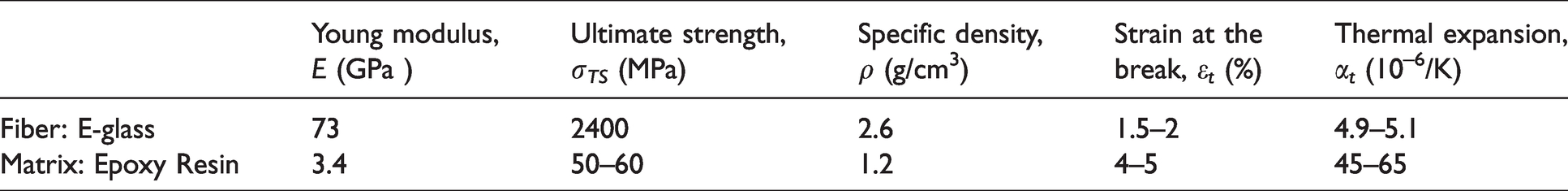
Composite tubes were specially fabricated for this study by İzoreel® Composites (Izmir, Turkey). E-glass/epoxy composite tubes are in 6 layers at the ±55° winding angle with filament wound technique. The fiber material used in the tubes was Vetrotex 1200 tex E-glass with 17 µm diameters whereas the matrix material was Bisophenol A, Epoxy CY 225. After being manufactured, the tubes were cured in an oven at a temperature of 135 °C for two hours. Table 1 shows the properties of the used fiber and resin. Figure 1 depicts the composite tube schematically.
Properties of the fiber and resin. 31
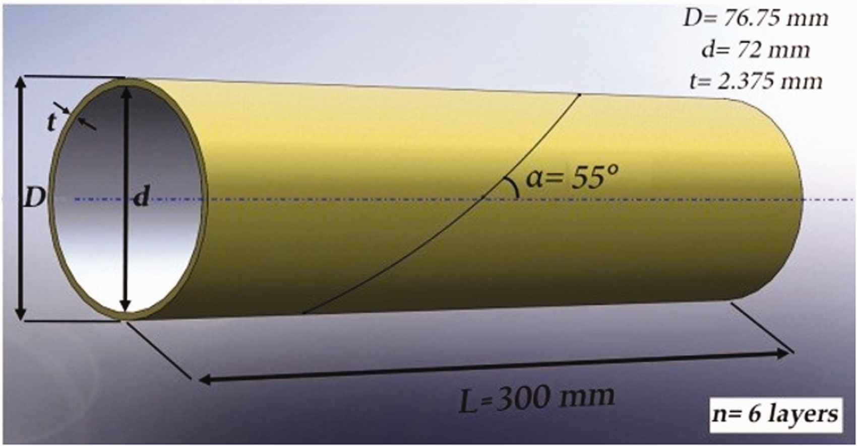
The geometry of the GFRP tube.
Providing of cryogenic conditions for composite tubes and low-velocity impact test
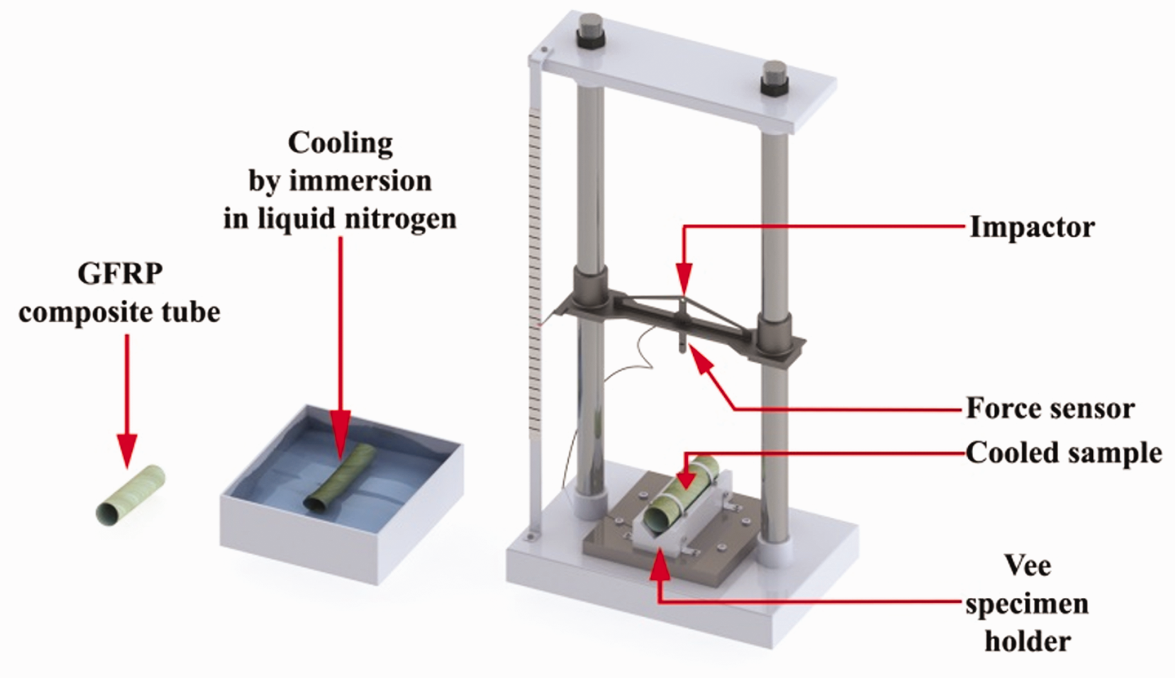
GFRP Composite tubes were immersed in liquid nitrogen to achieve low-temperature degree. Selected temperatures for this study are 77 K (liquid nitrogen temperature), 173 K, 223 K, 273 K, and 295 K (room temperature). Liquid nitrogen was taken from the nitrogen tank shown in Figure 2(a) and filled into a container, and the composite tubes were immersed in liquid nitrogen.
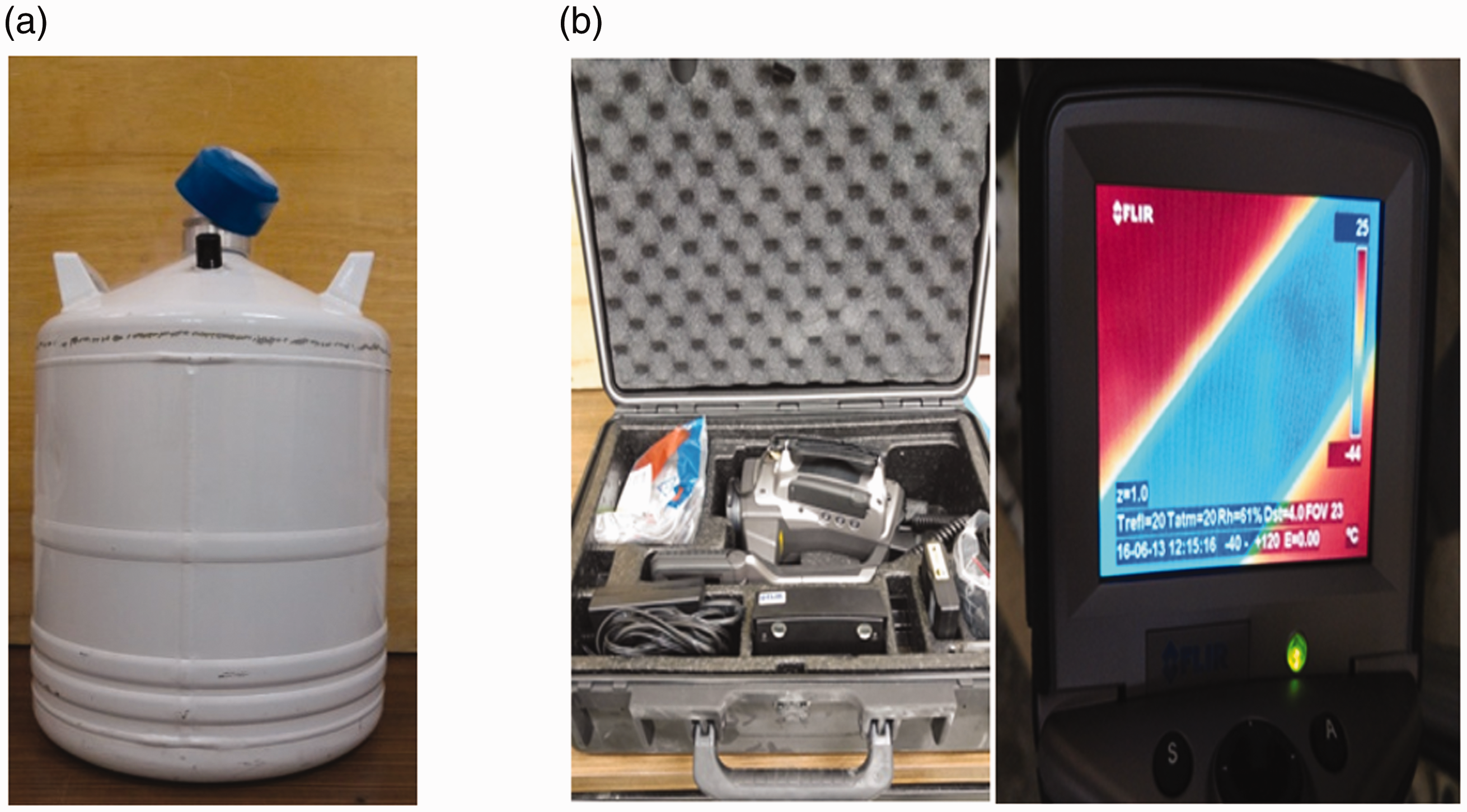
Liquid Nitrogen facility (a) Tank and (b) Thermal Camera.
A GFRP tube was allowed to stand in the liquid nitrogen-filled vessel for 10 minutes until it reached 77 K to get the variation of temperature versus time (or dubbed the heating curve) from the liquid nitrogen temperature of the GFRP composites to room temperature. Then, the temperature of the sample placed in the Vee-holder was determined with the help of a thermal camera (Figure 2(b)). The thermal camera can measure 228 K as lowest temperature. Depending on the time, temperature change was attained from 228 K to room temperature with 3° interval. Graphics part, from 77 K to 228 K was fitted to graphic by polynomial curve. Figure 3 shows the heating curve of the GFRP composite tube. Also, the equation of the curve fitting polynomial is provided on the graph. The composite tube retrieved from liquid nitrogen was subjected to low-velocity impact test as soon as the sample reached the desired temperature value by the times determined in the graph.
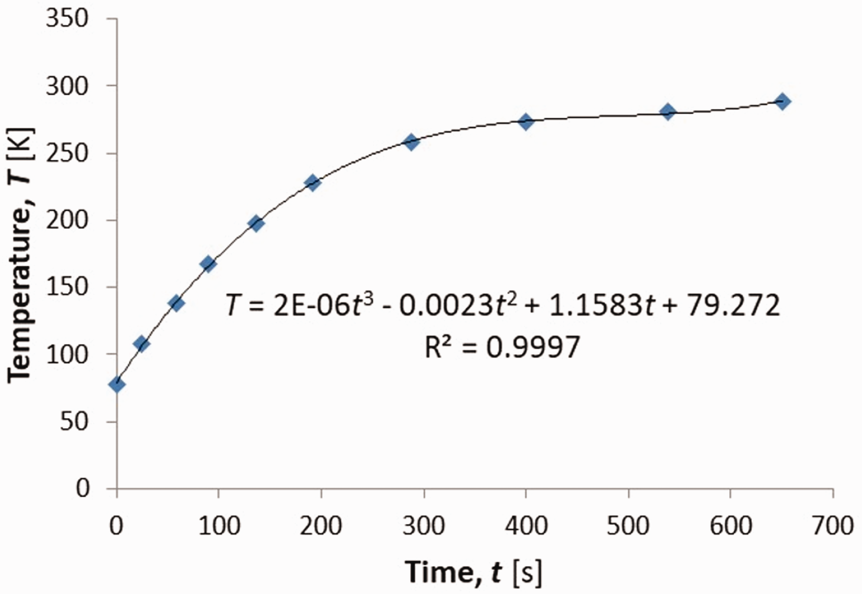
The heating curve of GFRP tube.
The LVI test rig (Figure 4) shows almost no frictional loss during impact. Hence, the deflection of the samples may not be retrieved from a measuring kit. So, the displacements can be calculated obeying Newton's second law of motion, as explained in Uyaner and Kara. 32 The subsequent calculations for absorbed energy, and the other parameters are performed numerically. Specially developed Excel Spreadsheet performed all calculations used in this work. 33
The low-velocity impact test rig.
The composite tube samples were retrieved from liquid nitrogen, laid onto Vee-holder, and sprayed with liquid nitrogen until the impact occurred to perform the test at liquid nitrogen temperature (77 K), as depicted in Kara et al. 30 The tubes were then subjected to LVI tests with the test-rig shown in Figure 4. The striker has hemispherical tip geometry with a 24 mm diameter and has a mass of 6.35 kg. LVI test levels are 5 J, 7.5 J, and 10 J.
Results and discussion
Burn test results of GFRP tubes
A burn test was performed according to ASTM-D2584-1834 to determine the fiber volume fraction of composite tubes used in the experiments. The fiber volume ratio of the GFRP composite tube, Vf, is 0.50.
Low-velocity impact test
Figure 5 shows the contact force-time histories for composite tube samples at different energy levels for five different temperature values. The striker rebounds at all temperatures and all energy values without puncturing the samples. The maximum peak force and the shortest contact time developed at the lowest temperature value of 77 K for all energy levels. The stiffness of the sample increases as the temperature drops. As a result, a higher contact force develops at the same energy level.
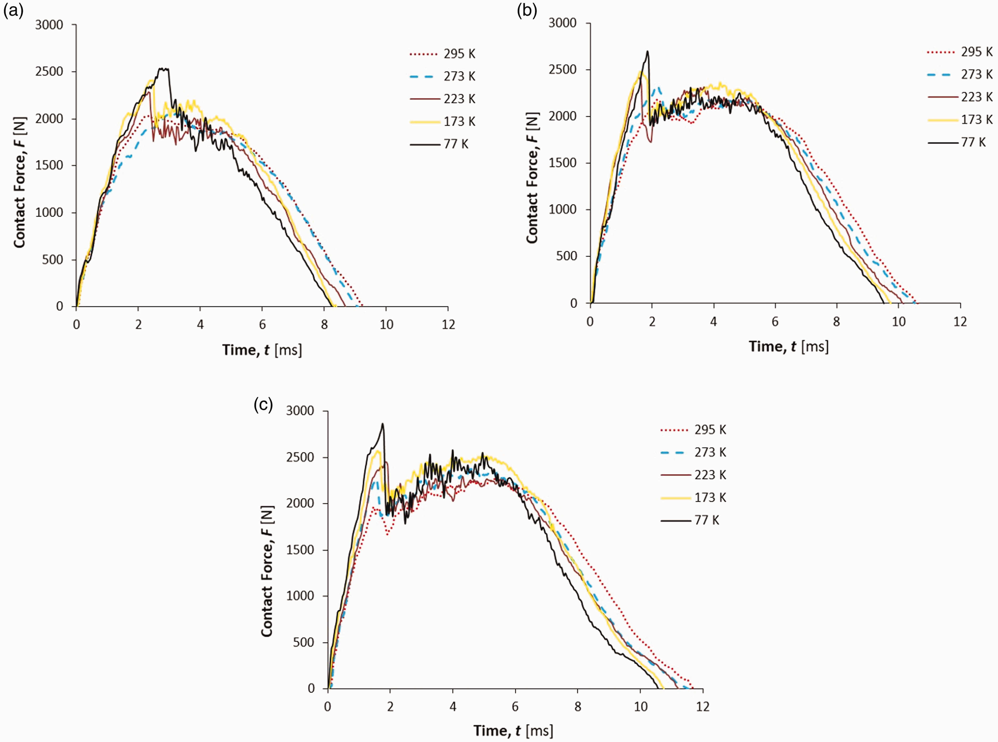
Force-time histories of GFRP composite tubes impacted at (a) 5 J, (b) 7.5 J, and (c) 10 J energy levels for various ambient temperatures.
As the temperature decreases, shear stresses occur at the fiber-matrix interfaces of the samples due to the thermal expansion mismatch of glass-fiber and epoxy (see Table 1). These stresses significantly increase the stiffness of the samples. Due to the increased sample stiffness, the maximum contact force was higher at low-temperature values. Kara et al. pointed out that as the stiffness decreases; the maximum contact force goes down. In LVI tests, because more damages develop as the energy level increases, more oscillations take place in the graphs. 30
During the impact event, the force increases rapidly, especially at low-temperatures. When reaching the maximum, it decreases abruptly. This value is defined as the force (F1) in ASTM D7136. Force F1 does not indicate damage initiation because non-critical matrix cracking and small delamination may occur at lower values. F1 represents the alteration of the stiffness, which is characteristic of the sample. 35 For the same energy level, the F1 force value appears to be higher at low temperatures. The peak force and contact duration increase with the increase of impact energy for each temperature value.
Figure 6 delineates the contact force-displacement variation for composite tubes impacted at different energy levels for various temperatures. In the experiments, no puncture occurred in any of the samples. Therefore, all graphs are in the form of a closed type curve. Due to the absence of puncture in the samples, the ultimate load that the samples can withstand was not obtained. As the impact energy level increases, the amount of displacement and force increases as well. The initial slope of the force-displacement curve is called bending stiffness owing to the resistance of the sample to the impact load. Variations and oscillations in bending stiffness indicate damage occurs in the sample. The bending stiffness increases as the temperature of the samples decreases. As the temperature of the test decreased, the maximum displacement value decreased due to the increase in stiffness.
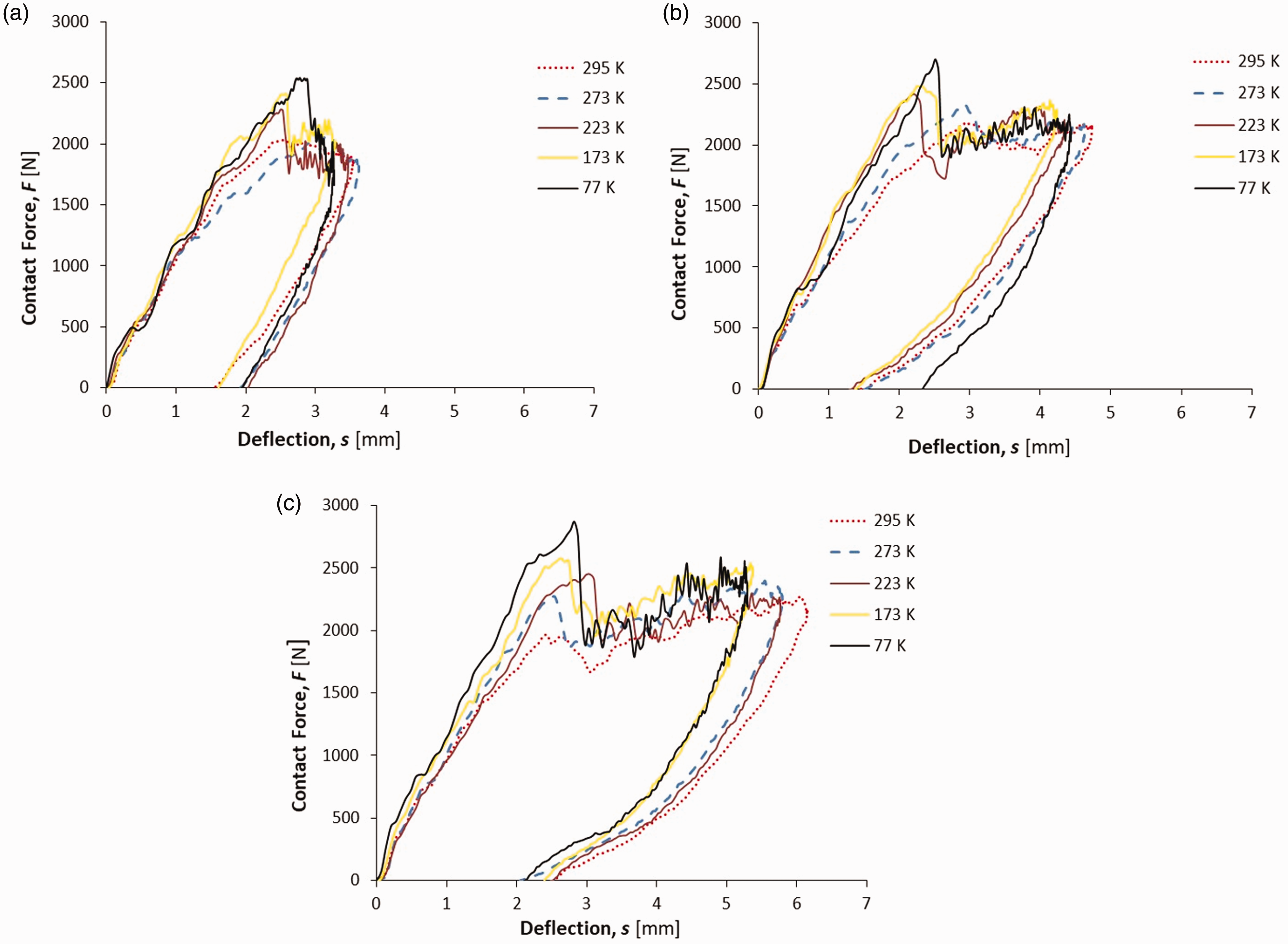
The variations of contact force by the displacement for GFRP composite tubes impacted at (a) 5 J, (b) 7.5 J, and (c) 10 J energy levels for various ambient temperatures.
Figure 7 shows the energy distribution graphs obtained for various impact energy levels. The absorbed energy by the sample slightly increases as the temperature value decreases for all energy levels. The decrease in temperature does not affect energy absorption if we ignore this small increment. Contrary to this finding, Ma et al. 9 found relatively low energy absorption at low-temperatures.
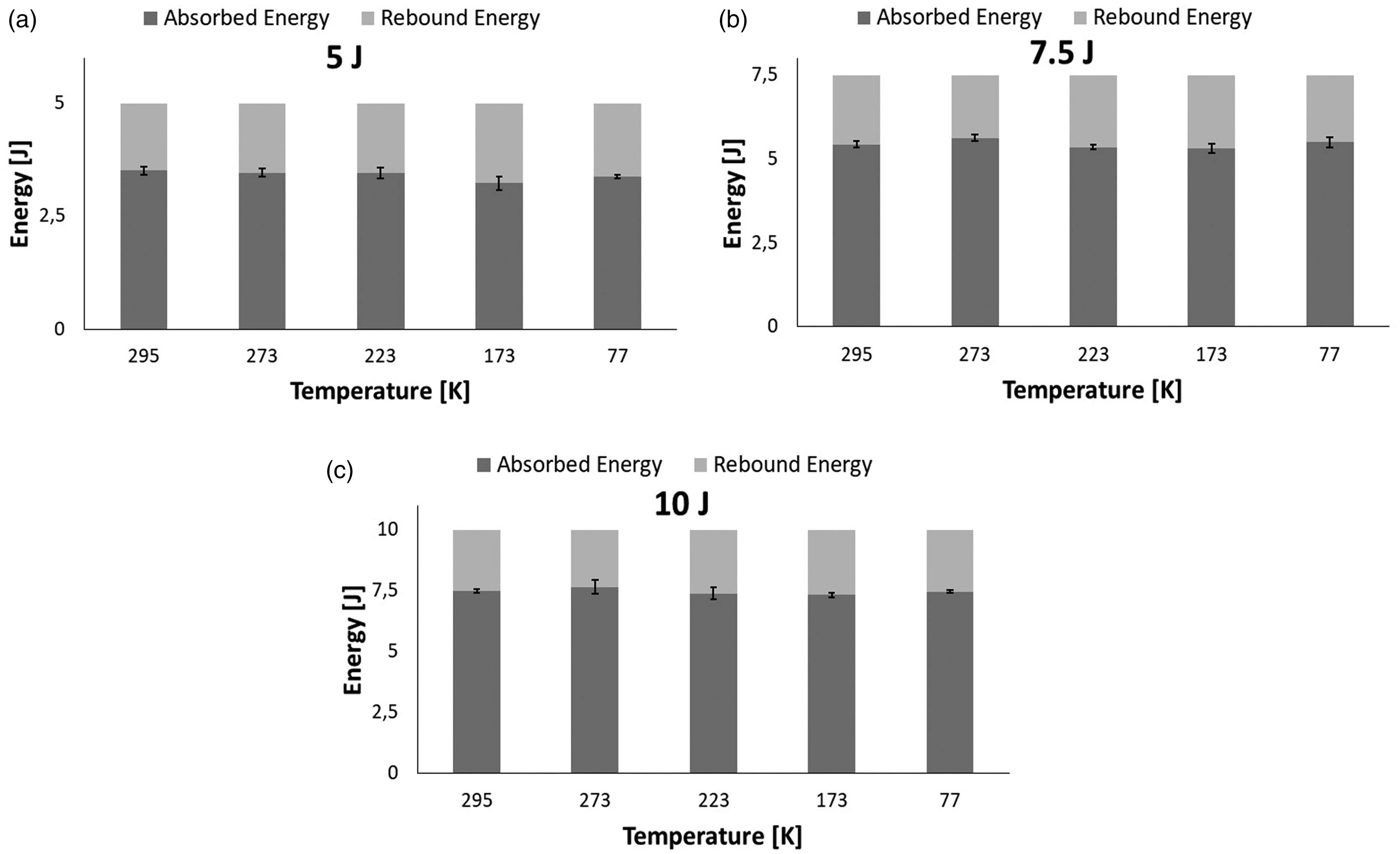
Energy balance of GFRP composite tubes impacted at (a) 5 J, (b) 7.5 J, and (c) 10 J for various temperature values.
Cryogenic effect
Firstly, all tubes used in the experiments were plunged in liquid nitrogen until they reached to the liquid nitrogen temperature. Then, we investigated preliminary damages due to thermal stresses caused by the immersion of samples in liquid nitrogen. During liquid nitrogen conditioning, cracking sounds emitted with the formation of micro-cracks, and these cracks can be seen clearly in SEM examination. 30 In this study, no cracking sound was heard in any sample during liquid nitrogen conditioning. Figure 8 shows the SEM images of the sample sections to detect of micro-crack formation. As a result of the examination, we could not detect micro-cracks in the samples conditioned with liquid nitrogen.
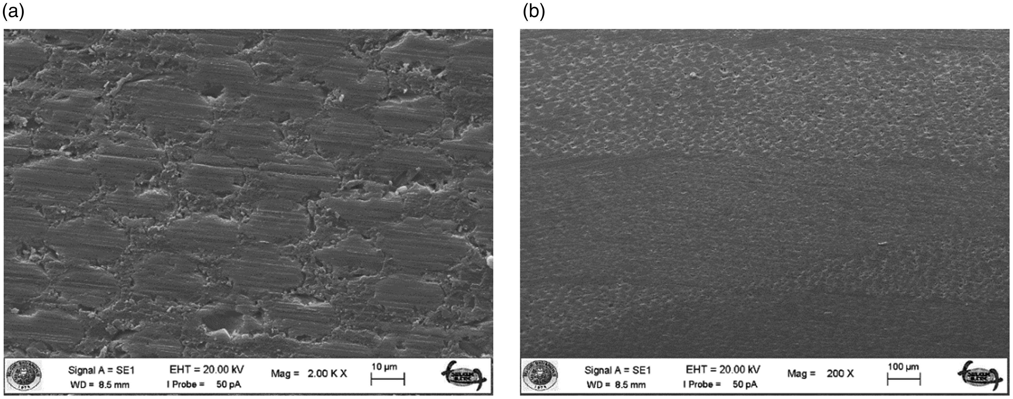
Cross-sectional images of samples held in liquid nitrogen at (a) 2000× and (b) 200× magnifications.
Damage mechanisms
Various damages may develop due to the low-velocity impact. Some of them are matrix cracking, delamination, fiber breakage, and fiber-matrix interface debonding.36,37 Damage mechanisms in GFRP samples exposed to impacts at different temperatures were determined and investigated. According to the literature review, damages to the samples can be determined by back lightning from the damaged area. When the damaged areas are viewed with the naked eye, the size and shape of the interlayer separation and matrix cracks can be detected. 38 High-resolution photographs of the anterior and posterior damaged zones of all tubes were taken and examined. Also, cross-sectional images of the samples cutting from the impact zones were obtained under a digital microscope.
Figure 9 shows the cross-sectional fractographs of the samples for the temperature values of 295 K and 77 K. Matrix cracks occur in the first layer of the thick composites due to the high local stresses. The damage develops from top to bottom to form the appearance of a pine tree. For thin layer composites, bending stresses on the back face of the composite initiate matrix cracks and delamination from the lowest layer, giving the appearance of an inverted pine tree damage. 38 Although composite pipes are thin-walled, they cannot bend freely due to the effect of temperature, and the spread of damage caused by impact has appeared as a pine tree. For the same energy level, the damaged area at 77 K is smaller than the damaged area at 295 K. Due to the increase in stiffness at low-temperature, less deflection occurred in the sample, and a smaller damage area formed.
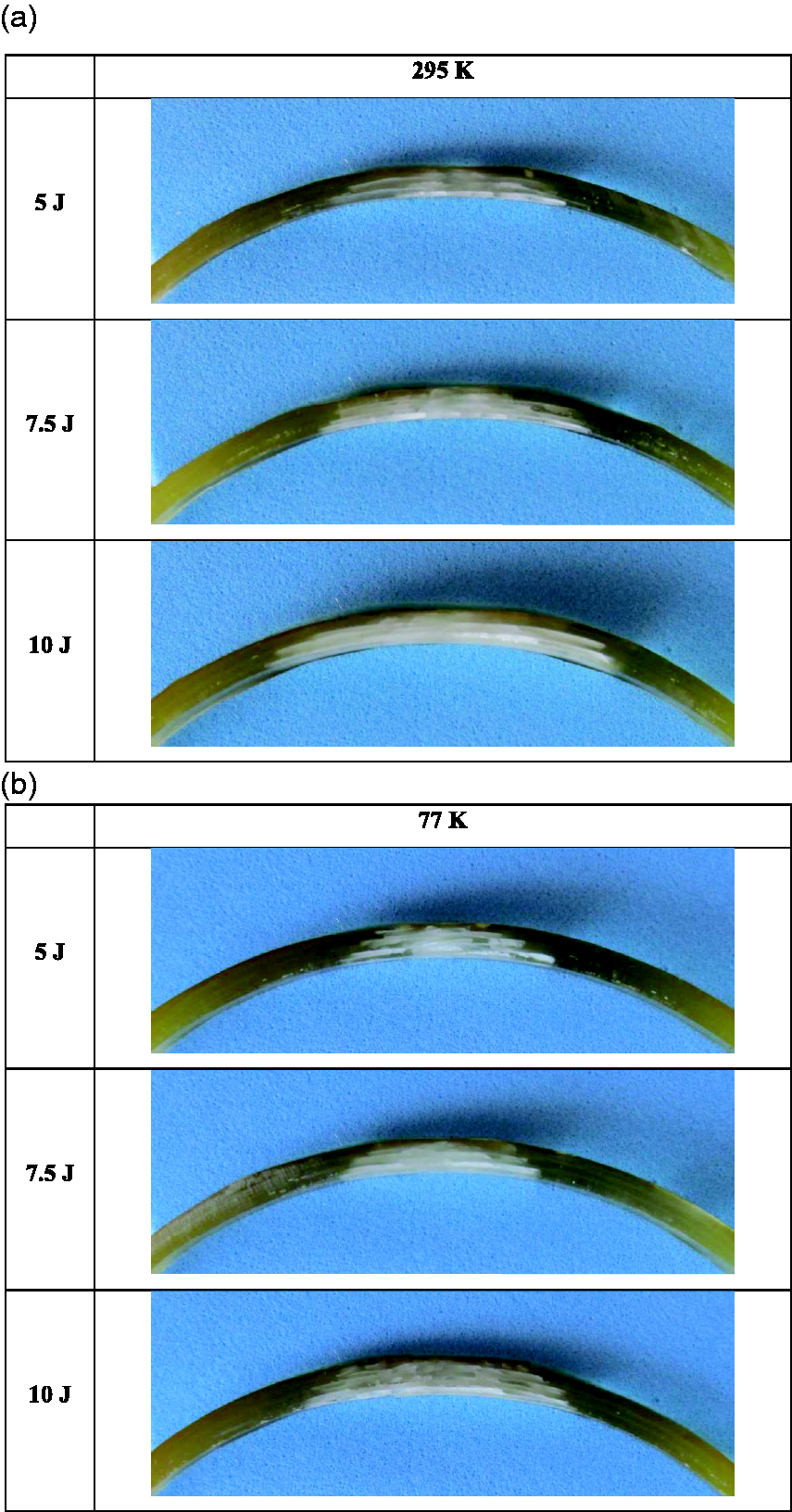
Cross-sectional fractographs for low-velocity impacted GFRP composite tubes for (a) 295 K and (b) 77 K ambient temperature.
Figures 10 to 12 show damage to the front, back, and cross-sectional areas of samples exposed to impact at different temperatures for the impact energy level of 5 J, 7.5 J, and 10 J, respectively. The overall damaged area gets more extended with increasing energy levels. Two distinct damage zones occur in the samples:

Fractographs for GFRP composite tubes 5 J impacted at (a) 295 K, (b) 223 K, and (c) 77 K.

Fractographs for GFRP composite tubes 7.5 J impacted at (a) 295 K, (b) 223 K, and (c) 77 K.

Fractographs for GFRP composite tubes 10 J impacted at (a) 295 K, (b) 223 K, and (c) 77 K.
The central zone is the center of the impact where the damage is due to the impactor penetration.
The second zone is the area where delamination and matrix cracks develop around the impact center.
Damage types that occurred after low-velocity impacts are mostly in the form of matrix crack and delamination.
There is a delamination area in the direction of fiber winding around the impact center. In layered composites, the flexural stiffness of the layers differs due to the different fiber orientations. The main reasons for delamination formation are bending-induced shear stresses and bending stiffness differences between layers. As a result, the delamination area spreads in the direction of fiber winding. 36 The back damaged area is smaller than the anterior ones.
It is evident that as the temperature value decreases for all energy levels, the damage areas in the samples decrease. The observed damages in the composites are radial matrix cracks and delamination, mainly. As the temperature decreased, sample stiffness increased, and less deflection occurred. As a result, the delamination areas remained smaller. However, due to the brittle structure of the sample, denser matrix cracks were observed at low-temperature values. Fiber breaks developed at cryogenic temperatures.
Figure 13 shows the variation of the overall damaged areas of the GFRP composite samples at various temperatures and for various impact energies. For each energy level and temperature value, the damaged area value given in the figure is the anterior damaged area that covers the whole damaged zone. It is clear that as the impact energy increases, the damaged areas increase. At the same energy level, the damaged area decreases as the temperature decreases, as expected before Ma et al. 9
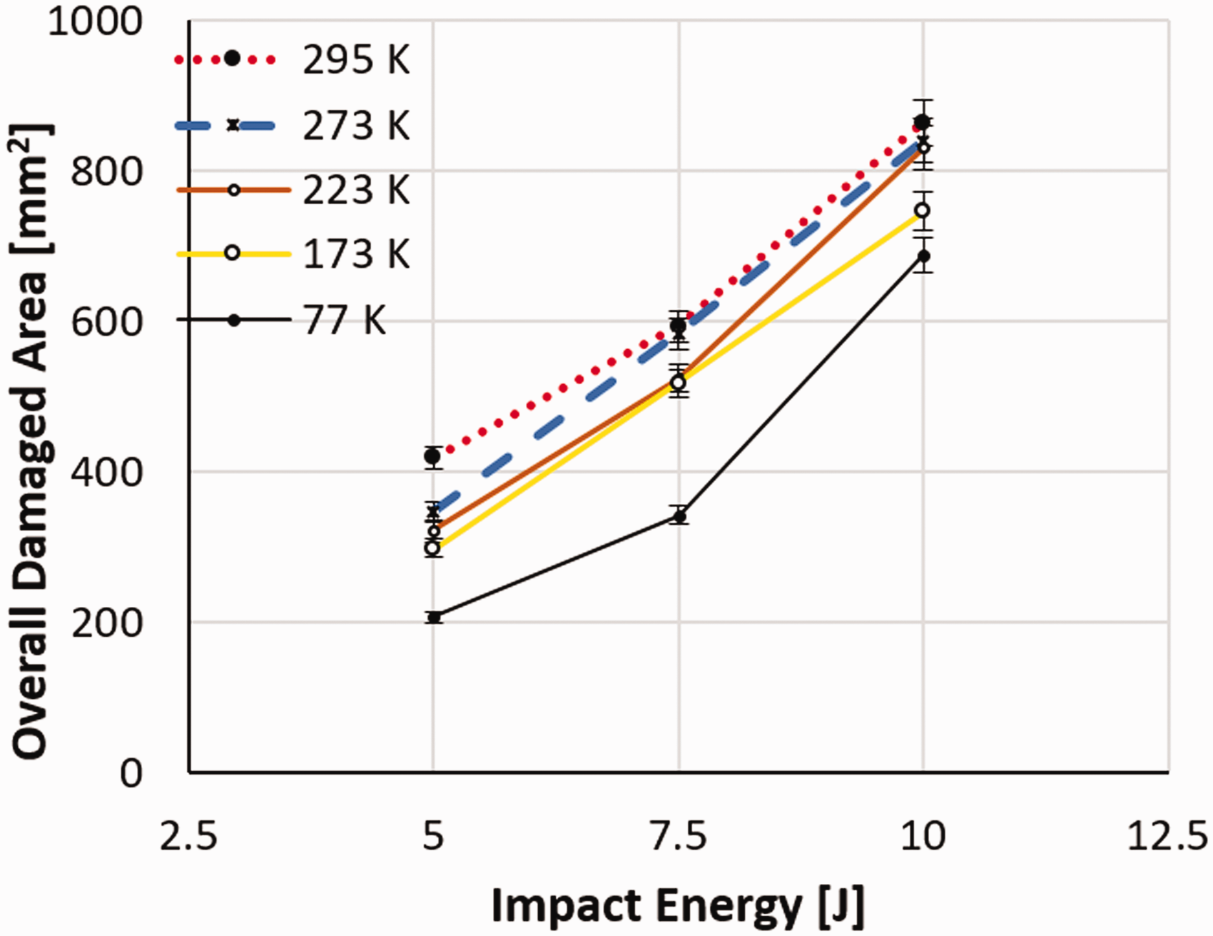
Variation of overall damaged area versus impact energy 5 J, 7.5 J, and 10 J impact energy levels.
Conclusions
This study covers both LVI response and developed damages of GFRP composite tubes under cryogenic environment conditions and room temperature. Remarkable conclusions are as follows:
The maximum contact force value and the shortest contact time occurred at 77 K for all energy levels. The smallest contact force and the longest contact time occurred in samples exposed to impact at room temperature (295 K). As the sample temperature decreased, the stiffness increased, and the amount of deflection decreased. The amount of energy absorbed by the samples increases with the increase of impact energy. In low-velocity impact tests on samples at different temperature values and at the same energy level, the amount of energy absorbed slightly increased due to the decrease in temperature. The damage areas of the samples at room temperature were more extended because of excess deflection. The damaged area decreases as temperature decreases. Also, dense matrix cracks occurred at low temperatures. The reason for this is that the samples are brittle at these temperatures.
Footnotes
Acknowledgements
This study is a part of a Master Thesis that carried out by Mustafa ARAT at Selcuk University, Institute of Science. Mesut UYANER and Memduh KARA are the advisors of this thesis. The authors would like to thank Muhammet KIRICI for his help in the realization of the experiments and the graphical sketch of the test rig.
Declaration of Conflicting Interests
The author(s) declared no potential conflicts of interest with respect to the research, authorship, and/or publication of this article.
Funding
The author(s) received no financial support for the research, authorship, and/or publication of this article.