
Abstract
Carbon nanotube (CNT) fiber/yarn reinforced composites are considered as a new generation of advanced materials for applications in aerospace and space industry. In this study, two types of CNT composite yarns were produced by twisting CNT films and infiltrating with thermoset epoxy (EP) and thermoplastic poly vinyl alcohol (PVA) resins. The tensile strength of CNT/PVA and CNT/EP composite yarn was 409.91 MPa and 206.87 MPa, much higher than that of pure CNT yarn (129.94 MPa). After mono-cryogenic condition, the mechanical and electrical properties of CNT/EP and CNT/PVA composite yarns were both enhanced due to the structure reorder of the CNT bundles and improvement of interfacial bonding. However, after 60 times cyclic-cryogenic conditions, CNT/EP composite yarn showed a ∼10% degradation of tensile strength; while CNT/PVA composite yarn exhibited 6% increment. This study provides fundamental data of the CNT reinforced thermoset and thermoplastic composite yarns for their practical applications in cryogenic environment.
Introduction
Carbon fiber reinforced polymer (CFRP) composites are increasingly used in aerospace and military fields due to their high specific strength, superior specific stiffness, and elevated impact resistance.1,2 CFRP composites are regarded as promising materials for lightweight design and low-cost manufacturing of aerospace crafts and reusable launch vehicles,3,4 such as composite tanks for storage of liquid oxygen (LO2) and liquid hydrogen (LH2) propellant.5,6 For a reusable launch vehicle, the composites tanks need to undergo repeatedly filling process of the low-temperature propellants.7,8 However, micro-cracks and even fracture were observed duo to residue stress for carbon fiber as well carbon fiber composites during cryogenic temperature variations. For example, Xu et al. 9 studied tensile and interfacial properties of polyacrylonitrile-based carbon fiber composites after different cryogenic conditions. They found that the generation of microcracks in cyclic-cryogenic conditions resulted in the degradation of the composite properties. Qu et al. 10 investigated the cryogenic mechanical properties and crack densities of hydroxyl-terminated polyurethane toughening epoxy/carbon fiber composites. They noticed carbon fibers were more likely to break than to separate from matrix duo to the strong interfacial bond. These studies have demonstrated vulnerability of carbon fiber composites and degradation of properties under cryogenic environment conditions.
As a new generation of advanced materials, carbon nanotube (CNT) fiber/yarn exhibits superior performance of the specific strength, stiffness, thermal resistance and the specific electrical conductivity.11–16 CNT fiber reinforced composites are attractive candidate materials for aerospace and space industry because they have an advantageous combination of low density, high strength, high stiffness, and high damping. 17 Previous works have focused on the mechanical properties of CNT fiber as well composites at cryogenic environment. Min et al. 18 found that CNT yarn exhibit excellent contraction/expansion reversibility during a multicycle of heating and cryogenic treatment, demonstrating a good elastic respond of the yarns. Ma et al.19,20 evaluated the effect of low temperature testing environment to the stress distribution and stress transfer efficiency in CNT/polymer composites and showed that the required axial stress to pull out a CNT at cryogenic temperature is more than 6 times greater than that required at room temperature. Feng et al. 21 reported that the introduction of MWCNTs into epoxy could enhance the cryogenic transverse composite strength and the interfacial strength of CNT reinforced polymer composites. However, the performance of CNT fiber reinforced polymer composites with high CNT loading under cryogenic condition is rarely studied.
CNT fiber reinforced polymer composites are prepared by a simple, controllable polymer infiltration approach, in which the polymer not only fill in the empty space within fibers, but also promote the interaction between CNTs.22–24 Epoxy and poly (vinyl alcohol) are typical thermoset and thermoplastic resins to be composed with CNT fibers.25–29 Epoxy (EP) as a commonly used matrix could form π-π interaction (∼10 kcal · mol−1) with the CNT due to the aromatic rings on the epoxy molecular backbone. 25 PVA is a flexible polymer material that has excellent adhesive property and excellent affinity to CNTs.26–29 The introduction of long-chain or cross-linked polymers enhances the interfacial properties between CNTs, which is the key to increase the properties of CNT fiber reinforced polymer composites.30–33 Therefore, the interaction between polymer and CNT fiber under cryogenic condition is worthy of further study.
In this study, the CNT composite yarns produced by twisting CNT films and infiltrating with thermal set (epoxy) and thermal plastic (poly vinyl alcohol) resins were manufactured and conditioned in cryogenic environment. The surface morphology, strain sensitivity and mechanical properties of composite yarns before and after cryogenic conditions were characterized and analyzed. Moreover, the mechanical and interfacial properties of CNT composite yarn under cyclic-cryogenic condition were compared and analyzed.
Experimental
Materials
The carbon nanotube (CNT) film, prepared by floating catalyst chemical vapor deposition method (FCCVD) was provided by the Suzhou Institute of Nano-tech and Nano-bionics. The thickness of the film was about 13.7 μm with a purity of >90%. The epoxy resin (JL-235) and curing agent (JH-242) were provided by Changshu Jia Fa Chemical Co. Ltd. (Zhejiang, China). Polyvinyl alcohol (PVA) particles were provided by Sinopec Shanghai Petrochemical Company, with a polymerization degree of 1788 and alcoholics degree of 98%.
Preparation of CNT composite yarns
The manufacturing process of CNT composite yarn (CNT-CY) was shown in Figure 1(a). The CNT film with width of 1 mm was firstly soaked in the polymer solution to be fully infiltrated and then twisted with 1200 r/m twist by an electric motor to form a thin yarn about 100∼200μm in lateral size. In this progress, the as-grown random networks of CNTs gradually form a certain directional three-dimensional interconnection network, so that obtain a uniform composite structure as shown in Figure 1(b). Then, CNT yarn was cured in a heating zone and CNT composite yarn (CNT-CY) was obtained. By this progress, CNT/EP composite yarn (CNT/EP-CY) and CNT/PVA composite yarn (CNT/PVA-CY) were obtained as shown in Figure 1(c).
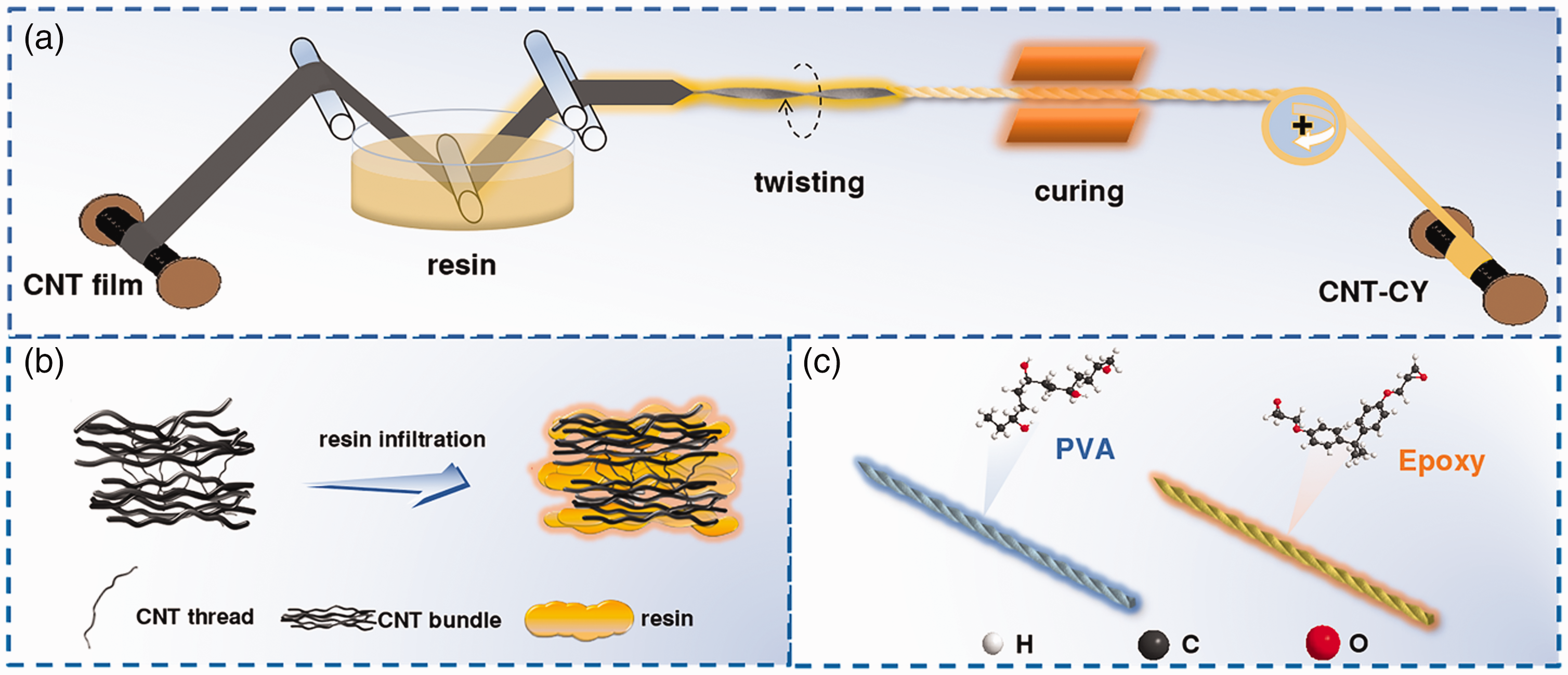
Schematic diagram of (a) the preparation of the CNT composite yarn, (b) three-dimensional crosslinking structure between CNT yarn and resin and (c) CNT/PVA and CNT/EP composite yarns.
Cryogenic treatment for CNT-CY
The temperature program-controlled method (TPCM) was carried out in a temperature-programmable cryogenic chamber (SXL-30, Institute of physics and chemistry, Chinese Academy of Sciences). Firstly, the atmospheric temperature was reduced from room temperature to −196 °C directly, then maintained at −196 °C for 12 hours and lastly rewarmed up to room temperature keeping the rate of 2 °C/min. The CNT-CY was firstly positioned in cryogenic chamber under −196 °C for 2 minutes, and then it was placed at room temperature for 2 minutes to complete a cycle. And 20, 40, and 60 cycles were performed respectively to complete the cyclic-cryogenic treatment test.
Characterization
The yarn diameter was measured by a light microscope (ECLIPSE LV100 POL, Nikon) using a digital photographic system. 20 specimens were tested for each sample to obtain a mean value. Tensile test was conducted by a single fiber tensile testing machine (XQ-2, Shanghai Xusai Instrument Co. China) at a tensile speed of 0.5 mm/s and a gauge length of 10 mm. Therefore, a multi-meter (Agilent 34410 A, USA) with two-probe was used to investigate the electrical resistance. Lastly, the morphology of yarn surface and fracture surface was observed by a Scanning Electron Microscope (SEM, TM-3000, Hitachi).
Results and discussions
Surface morphologies and physical properties
SEM pictures of the surface morphology of three types of CNT based yarns were shown in Figure 2(a) to (f). It can be seen that in the pure CNT yarn, CNT bundles and gaps between bundles were clearly visible. However, according to Figure 2(g), the Raman spectra of CNT yarn have shown a sharp peak at 1590 cm−1 demonstrating a well-organized structure of CNTs. Observing XPS spectra of CNT yarn as shown in Figure 2(h), the C1s nuclear polarography of CNT yarn demonstrated the stability of CNTs structure with the presence of both sp3 and sp2 bond for π-π* interaction but without covalent bonding. For the CNT/EP-CY, the diameter increment revealed that more epoxy was remained on the surface due to its high viscosity. On the contrary, it was easier for PVA to enter the interior of the CNTY due to the low viscosity and good affinity to CNTs. Furthermore, the wettability between PVA and CNTs makes PVA fill the interior spaces inside yarn, drawing CNTs close and sticking CNTs together, which then decreases the diameter of the yarn.
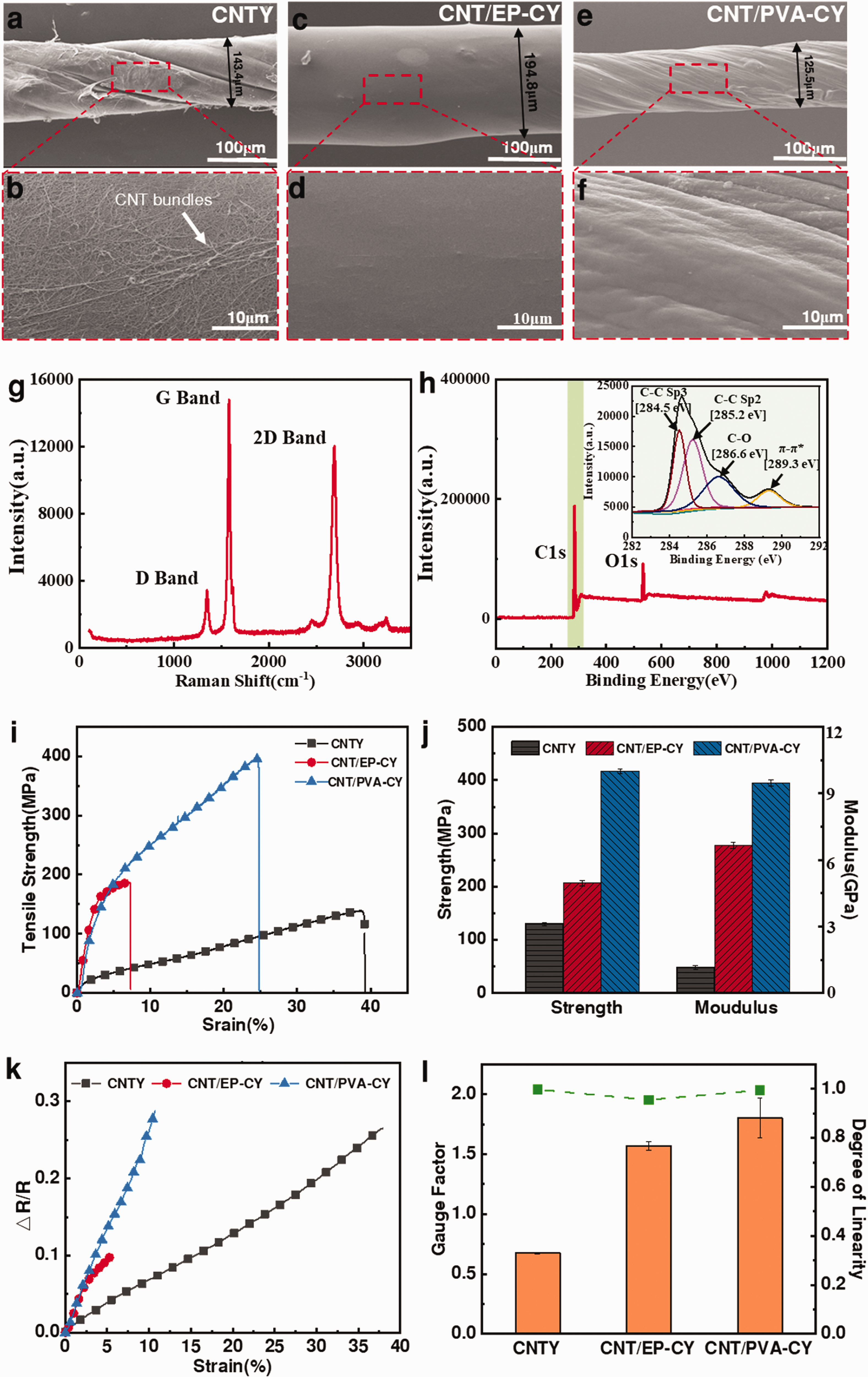
SEM images of (a and b) CNTY, (c, d) CNT/EP-CY and (e and f) CNT/PVA-CY. (g) Raman spectroscopy of D- and G-bands and (h) XPS spectra for CNTY. (i) Typical stress-strain curves. (j) Tensile strengths and modulus. (k) Resistance changing rates and (l) gauge factors and degree of linearity.
Typical tensile stress-strain curves in Figure 2(i) and (j), the tensile strength and modulus of CNT/EP-CY reached 206.87 MPa and 6.67 GPa, respectively. While the tensile strength and modulus of CNT/PVA-CY (409.91 MPa and 9.48 GPa, respectively) showed 98% and 42% higher than those of CNT/EP-CY, 315% and 8 times than those of pure CNTY (129.94 MPa and 1.168 GPa, respectively). This is because the penetrated PVA increased stress transfer between CNT bundles. For CNT/EP-CY, excessive polymer attached onto the surfaces of yarn due to high viscosity, rendering the limited increment of tensile strength. In addition, for epoxy matrix, translational movements of the molecular segments are highly constrained by the chemically cross-linked 3D network. 29 Although such molecular rigidity significantly elevates the strain transfer efficiency, it also impairs the ductility of the CNT network leading a significant decrease in tensile strain (∼8% tensile strain). In contrast to epoxy, plastic flow is possible for PVA matrix with the orientation and stretching of linear PVA molecules, which still leads to 25% tensile strain.
Due to the intrinsic piezoresistive characteristic of individual CNT, the resistance of CNT will increase under stretched. As the CNT network assembly, the CNT composite yarn also exhibited piezoresistive characteristic. Herein, the gauge factor (GF), which defined as value of the divider of the resistance changing ratio (ΔR/R0, where R0 is initial resistance and △R is the resistance changing) with strain, was adopted to evaluate the strain sensitivity. As shown in Figure 2(k) and (l), the CNT/EP-CY exhibited a GF of 1.57 and 5% stress strain. However, the effective strain of CNT/PVA-CY was still 10%, accompanied with a higher GF of 1.8 and good linearity (∼99.7%). The high resistance changing rate and GF reflects an effective stress transfer between the yarn and the matrix.
Properties of CNT composite yarns after Mono-cryogenic condition
The process of mono-cryogenic condition was shown in Figure 3(a). Firstly, the atmospheric temperature was reduced from room temperature to −196 °C directly, then maintained at −196 °C for 12 hours and lastly rewarmed up to room temperature keeping the rate of 2 °C/min. As shown in Figure 3(b) and (c), compared with untreated CNT-CYs, the cryo-treated CNT/EP-CY (242.9 MPa) and cryo-treated CNT/PVA-CY (529.1 MPa) achieved 26% and 31% higher tensile strength, respectively. Moreover, the tensile strain of cryo-treated CNT/PVA-CY was increased to 33%, which was even higher than that cryo-treated CNTY (∼28%).
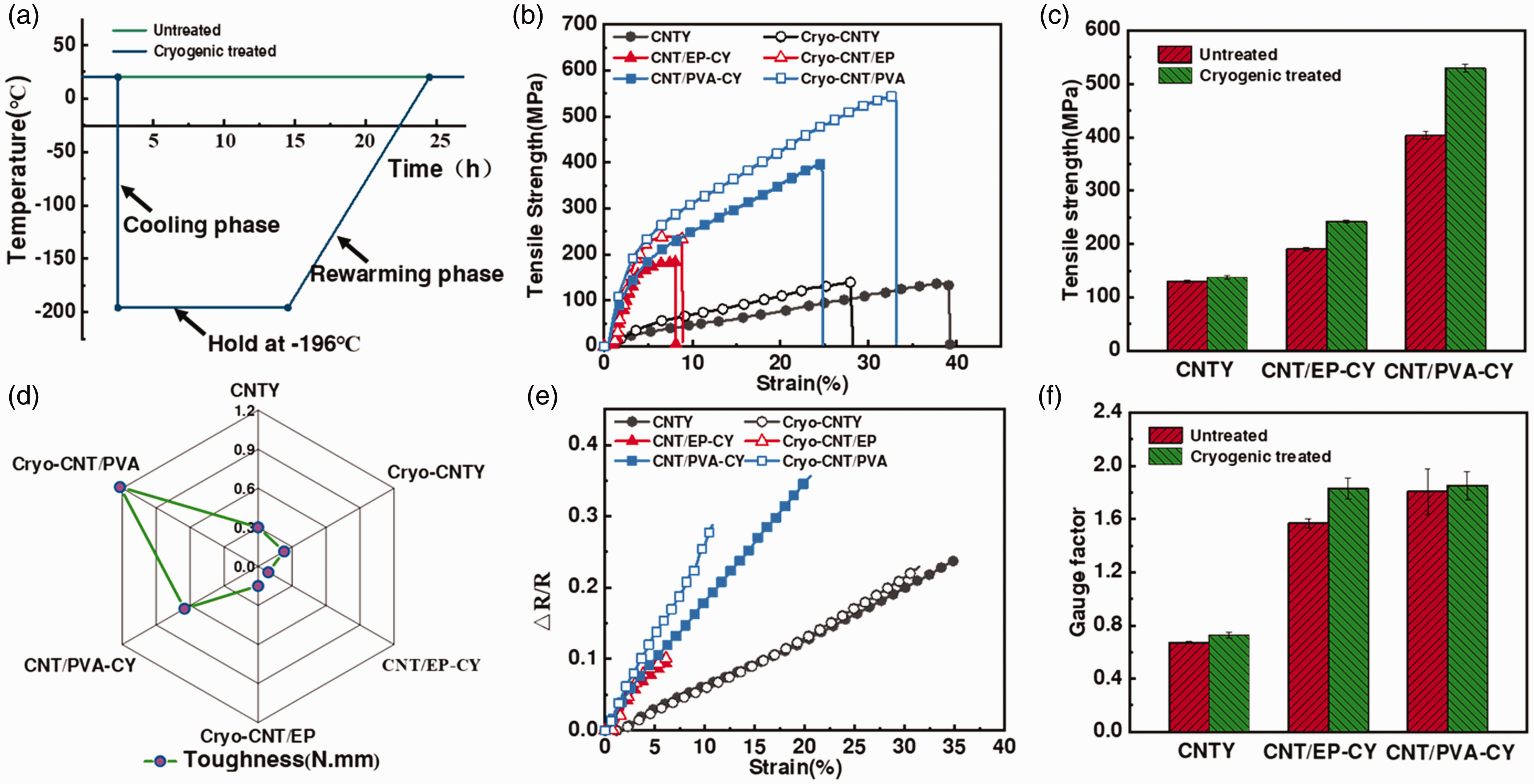
(a) Process of mono-cryogenic treatment. (b) Typical stress-strain curves. (c) Tensile strengths. (d) Tensile toughness. (e) Resistance changing rates and (f) gauge factors of different yarns before and after cryogenic condition.
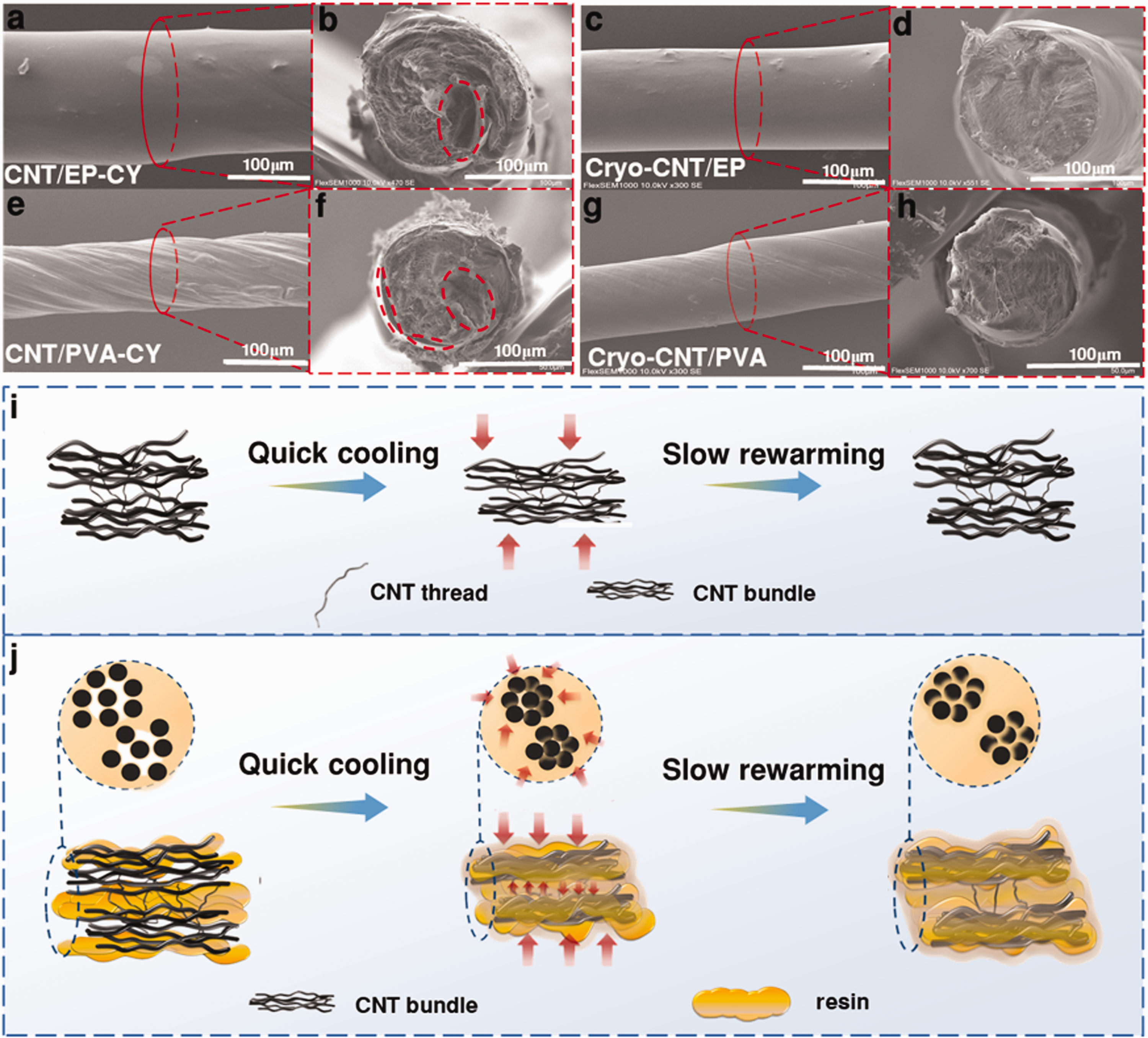
SEM images of yarn surfaces and cross sections of (a, b) CNT/EP-CY, (c, d) Cryo-CNT/EP, (e, f) CNT/PVA-CY, (g, h) Cryo-CNT/PVA. Mechanism of polymer infiltration for (i) pure CNT yarn and (j) CNT composite yarn under cryogenic condition.
Toughness is the ability of materials to absorb energy when it’s deformed or broken, which is the comprehensive embodiment of the strength and plasticity. Figure 3(d) illustrates the toughness of cryo-treated CNT/EP-CY still increased by 60% from 0.09 N · mm to 0.15 N · mm. While the tensile toughness of cryo-treated CNT/PVA-CY reached 1.2 N · mm, which is about 189.5% higher than that of untreated CNT/PVA-CY (0.65 N · m). The decrease of tensile strain of CNTY leads to the decrease of toughness. The chemically cross-linked 3D network for epoxy constrains the movements of the molecular segments, which impairs the tensile strain of CNT/EP-CY resulting in poor toughness. Moreover, the resistance changing rates of CNT-CYs before and after cryogenic condition showed a similar trend as shown in Figure 3(e). The GF of cryo-treated CNT/EP-CY was improved 20% from 1.5 to 1.8, which may because the cryogenic condition was beneficial to the interfacial bonding and stress transfer in the composites.
Mechanism of structure changing of cryogenic conditioned CNT-CY
As shown in Figure 4(a) to (h), after mono-cryogenic condition, the resin layers on both CNT/EP-CY and CNT/PVA-CY were more uniform and smoother. In addition, for their tensile failure cross sections, the reduction of the gullies and cracks were observed due to the enhanced interfacial bonding in mono-cryogenic conditioned CNT-CYs. Due to the mismatch of the coefficients of thermal expansion (CTE) between CNT bundles (−1.8 × 10⁻⁵ °C−1) and resins (7∼10 × 10−5°C −1),34–36 the thermal shrinkage caused by cryogenic condition will push more resin layers into the porous structure of CNT bundles and make the resin matrix gripped the CNT bundles tightly, thus improving the bond between resin and CNT bundles, as shown in Figure 4(j). In addition, the CNT yarn consists of flexible and entangled CNT bundles, the shrinkage leads to the consolidation of the CNT bundle structure, which could make a better orientation of the CNT bundles in the yarn and effectively shorten the carbon-carbon bond distance. This relatively strong bonding led to a better stress transfer between the resin matrix and the CNTY, enhancing the reinforcing efficiency of the CNTY in the composite.
Moreover, the hoop stress induced by the cryogenic process may cause rearrange of the CNT bundle and resins distribution, lead to more structural homogeneity and less extrinsic defects, resulting in the improvement of its mechanical properties. Compared to epoxy, the plastic flow for linear PVA molecular is more beneficial to the rearrangement of CNT bundles and resin distribution under the action of hoop stress, which led to a higher performance improvement of CNT/PVA-CY than CNT/EP-CY after cryogenic condition.
The properties of CNTCY under cyclic-cryogenic condition
The composites need to withstand large cyclic temperature variations and extremely low temperatures for use in next generation reusable space launched vehicles, such as the lightweight liquid hydrogen fuel tanks.5,6 The creep flexibility of matrix of the composites will decrease under the cyclic low temperature condition, which leads to the occurrence of microcracks and the decrease of its service life. 37 The process of cyclic-cryogenic treatment of three yarns was shown in Figure 5(a). The yarns were firstly positioned in cryogenic chamber under −196°C for 2 minutes, and then they were placed at room temperature for 2 minutes to complete a cycle. And 20, 40, and 60 cycles were performed respectively to complete the cyclic-cryogenic treatment test.
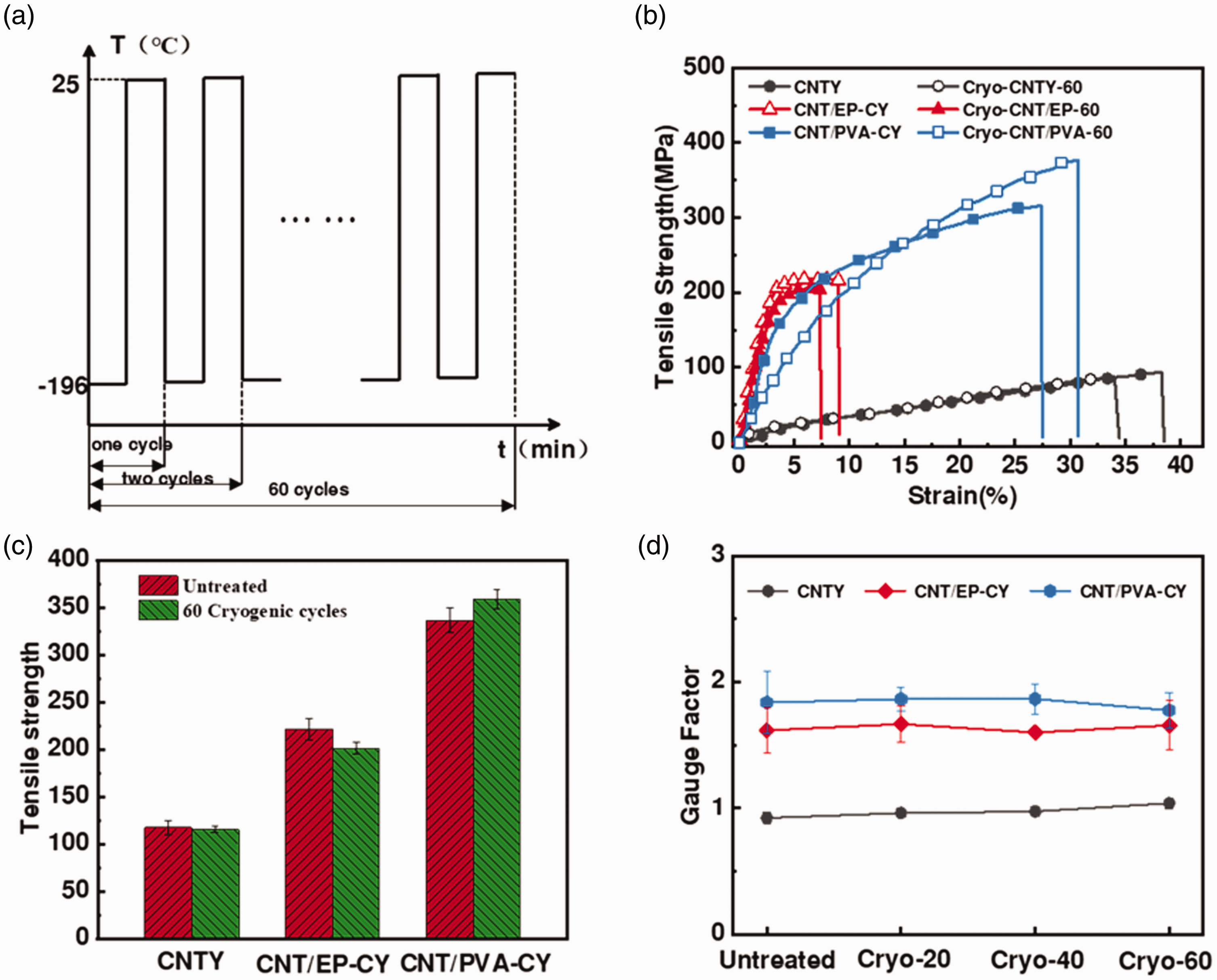
(a) Process of cyclic-cryogenic treatment. (b) Typical stress-strain curves. (c) tensile strength of CNT-CY before and after cyclic-cryogenic condition. (d) Gauge factors of CNT-CYs after different cryogenic cycles.
As shown in Figure 5(b) to (d), after 60 cycles of cryogenic treatment, the mechanical properties and GF of CNTY remained stable due to excellent contraction/expansion reversibility. The tensile strength of CNT/EP-CY was decreased by 10.5% after 60 cycles of cryogenic treatment. This is because the generation of residual thermal stress caused by the difference of thermal expansion coefficient between CNT bundles and epoxy under cyclic-cryogenic condition. The highly cross-linked 3D molecular network within epoxy makes it exhibit strong rigidity under the cyclic-cryogenic temperature change, which damage the bond between epoxy and CNTY, leading to the decline of tensile strength. As a thermoplastic resin, PVA showed a good response to the repeated expansion and contraction of CNTY due to the retention of the relaxation of polymetric segments after cyclic-cryogenic condition, which can rearrange the PVA structure to enhance the flexibility, thus increasing the tensile strength of CNT/PVA-CY by 6% and the tensile strain by 20%.
Conclusion
In this study, the CNT/EP-CY and CNT/PVA-CY were fabricated by twisting CNT films infiltrated with epoxy or PVA solution and cryogenically conditioned. The resultant CNT/PVA-CY exhibited 98% and 315% higher tensile strength (409.91 MPa) than those of CNT/EP-CY and pure CNT yarn. After mono-cryogenic condition, compared to CNT/EP-CY, CNT/PVA-CY exhibited better interfacial bonding, which led to 31% higher tensile strength (529.1 MPa) and 189% higher tensile toughness (1.2 N · mm) than that of untreated CNT/PVA-CY, accompanied with 33% tensile strain. Under cyclic-cryogenic condition, CNT/PVA-CY after 60 times cyclic-cryogenic condition exhibited 6% increment of tensile strength. This study provides fundamental data of the CNT reinforced thermoset and thermoplastic composite yarns for their practical applications in cryogenic environment.
Footnotes
Declaration of Conflicting Interests
The author(s) declared no potential conflicts of interest with respect to the research, authorship, and/or publication of this article.
Funding
The author(s) disclosed receipt of the following financial support for the research, authorship, and/or publication of this article: This work was financially supported by the Shanghai Natural Science Foundation (Grant No. 20ZR1402200) and Fundamental Research Funds for the Central Universities (Grant No. 2232021G-01).