






Abstract
The dynamic response of composite sandwich structures with honeycomb-foam hybrid cores subjected to underwater shock waves was investigated by numerical simulations. The deformation process, core compression, momentum transmitting characteristics, and energy absorbing properties of sandwich structures subjected to underwater shock waves with different initial pressures were analyzed. The dynamic responses of the composite sandwich with different core configurations were also compared. The results show that the composite sandwich structures can provide superior protection from underwater shock waves than mass equal laminate plates and the sandwich structures with hybrid cores have better performance than that with empty honeycomb cores when subjected to underwater shock waves. The research can provide reference for the lightweight design and optimization of protective structures against underwater blast loading.
Keywords
Introduction
During the design of protective structures, both the protective performance and quantity should be considered, providing that the lightweight design of structures has become a key factor in the evaluation of protective properties. During the past several decades, investigations on the dynamic response of sandwich structures1, 2 under high-velocity impact 3 and air or water blast 4 with experimental 5 and numerical methods 6 were conducted by researchers.
Over the last few decades, metallic sandwich structures have been the focus of the research related to protective issues, and massive research have been conducted relating to the water blast response of metallic sandwich structures.7–11 According to the work of Fleck et al., 12 the dynamic response of sandwich structures subjected to underwater shock waves can be divided into three stages, that is, the fluid-structure interaction (FSI) phase, the core compression phase, and the dynamic structural response phase. The transmitted momentum, the core compression strain, and the maximum central deflection of the back face sheet of the sandwich structure can be predicted through the theoretical model. McShane et al. 13 investigated the underwater blast response of clamped sandwich beams with the Y-frame, corrugated core, and an ideal strength isotropic foam core, and the regimes of behavior of the underwater blast response for sandwich beams were clarified. McShane et al. 14 measured the underwater blast response of free stranding metallic sandwich plates with a square honeycomb core and a corrugated core using the experimental method. Tilbrook et al. 15 used finite element calculations to describe the dynamic response of sandwich beams subjected to underwater blast, and the effects of FSI were also considered. Huang et al.16, 17 conducted FSI experiments to analyze the dynamic response of metallic sandwiches with honeycomb and foam cores against water-based impulsive loads and the effects of core, loading area, and loading intensity on the dynamic response, and failure modes of the structures were discussed. The research shows that the sandwich structures is determined not only by the transmitted impulse but also by the failure modes and the energy dissipation mechanism of the cores. D J Ai et al. 18 investigated the response of foam core sandwich panels subjected to near-filed and contact underwater explosion based on numerical simulations, providing that a thinner top face sheet and a thicker bottom face sheet are beneficial for sandwich panel design.
The metallic sandwich structures have shown apparent advantages in blast resistance comparing with the monolithic metallic plates. Nowadays, with the development and extending applications of the fiber reinforced polymer composite materials (FRP), sandwiches with FRP materials have been used by many researchers for lightweight design of load bearing and energy absorbing structures. A number of research on the mechanical properties of sandwich structures from carbon fiber reinforced composite materials were conducted.19–23 Schiffer and Tagarielli 24 analyzed the dynamic response of composite plates to underwater blast via theoretical and numerical modeling, based on which the design charts were constructed and used to determine the plates designs to improve the water blast resistance. Sandwich beams with square honeycomb cores were manufactured from carbon fiber composite sheets and tested in three-point bending by Russel et al. 25 Russel et al. 26 investigated the dynamic response of sandwich beams with the carbon fiber composite square honeycomb core under the impact of metal foam projectiles to simulate localized blast loading. Zhou et al. 27 numerically analyzed the dynamic response of square honeycomb-cored sandwich plates made from carbon fiber reinforced composites subjected to underwater shock waves. Ren et al. 28 experimentally evaluated the underwater impulse resistance of the carbon/epoxy composite sandwich with the PVC foam core. Overall, research on the dynamic response of sandwich structures with fiber reinforced composite materials subjected to underwater blast loading are still in an initial stage, and relevant analysis need to be performed.
In this paper, the dynamic response of carbon fiber reinforced composite (CFRP) sandwich plates with honeycomb-foam hybrid cores was investigated by numerical simulations; the outline of this paper is as follows. First, the composite sandwich plate with the honeycomb-foam hybrid core was proposed, and the numerical model of the composite sandwich plates subjected to underwater shock waves was established. Then, the dynamic response of the composite sandwiches with honeycomb-foam hybrid cores was numerically analyzed; the deformation process and energy absorption of the sandwiches, the core compression properties, and momentum transmitting characteristics of sandwich plates with hybrid cores of different relative densities were discussed. The comparison of the protective properties of composite sandwich plates with different core configurations was also performed. The research can provide reference for the lightweight design of the protective structures subjected to underwater shock waves.
Numerical modeling
Composite sandwich structures with the honeycomb-foam hybrid core
The novel CFRP sandwich structure with the honeycomb-foam hybrid core is illustrated in Figure 1. The sandwich is composed of two rigid face sheets and a honeycomb-foam hybrid core. Two thickness-identical face sheets are made from 0 to 90 deg laminates with unidirectional carbon fibers embedded within an epoxy resin system. Each ply of the laminate was approximately 0.4 mm thick with a density of ρfs = 1525 kg/m3. Illustration of the CFRP sandwich structure with the honeycomb-foam hybrid core.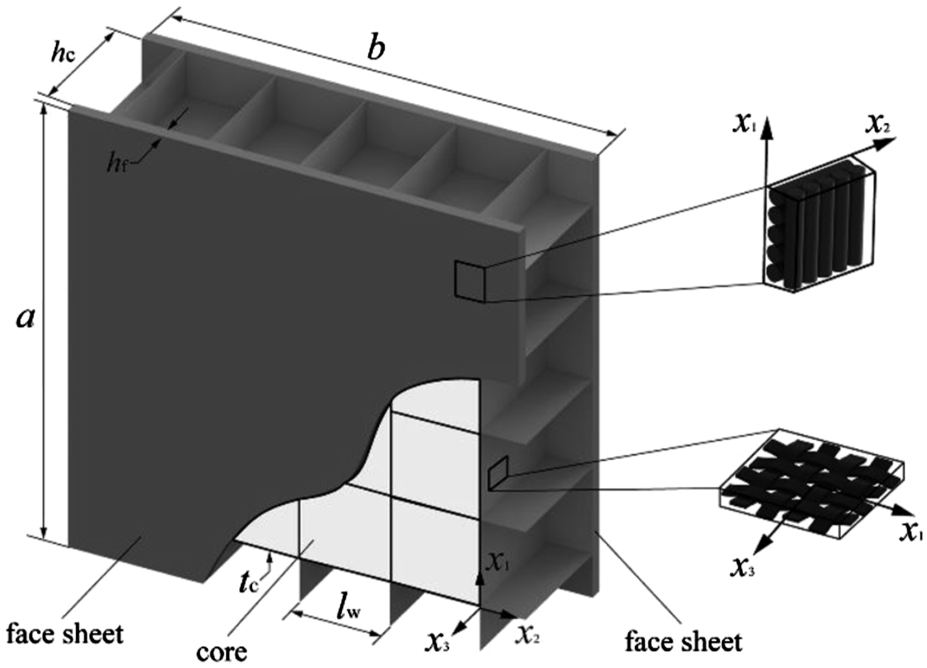
The configuration of the honeycomb-foam hybrid core is shown in Figure 2. The core consists of a square honeycomb and foam fillers, and detailed description of the preparation of the core can be found in the research of H Zhou et al.
29
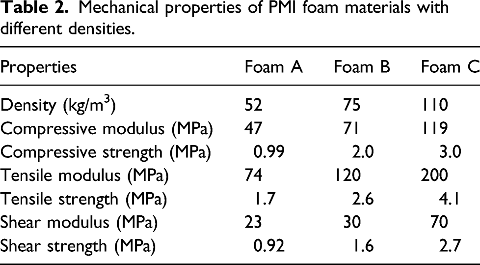
The square honeycomb core was manufactured by assembling together slotted woven carbon fiber composite sheets of thickness tw = 0.4 mm and density ρw = 1450 km/m3. The main mechanical properties of two kinds of CFRP materials in this research is shown in Table 1. Illustration of the honeycomb-foam hybrid core. Mechanical properties of CFRP materials used in this research.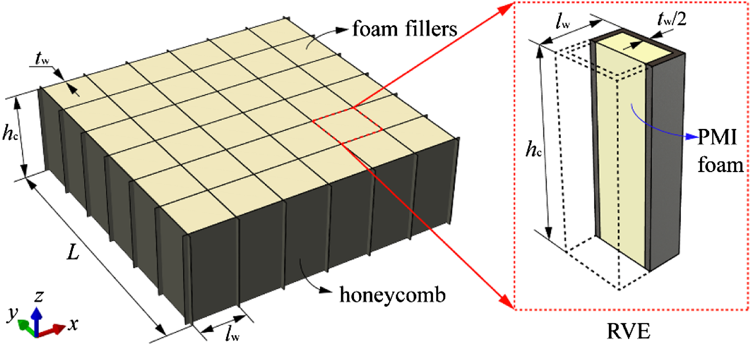
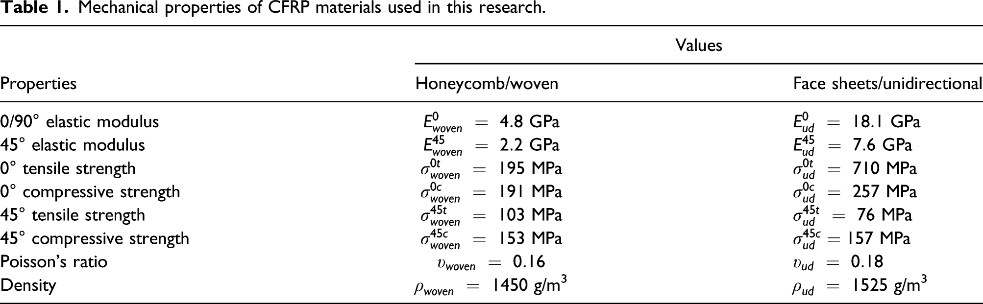
Mechanical properties of PMI foam materials with different densities.
Geometrical model and meshing
The numerical model of the sandwich structure subjected to underwater shock waves is sketched in Figure 3. Clamped boundary condition was applied at the edges of the back face sheet of the sandwich structure. Typical pressure history of shock waves generated by underwater blast can be described by an exponentially decaying free-field pressure versus time equation as below Numerical model of the sandwich structure subjected to underwater shock waves.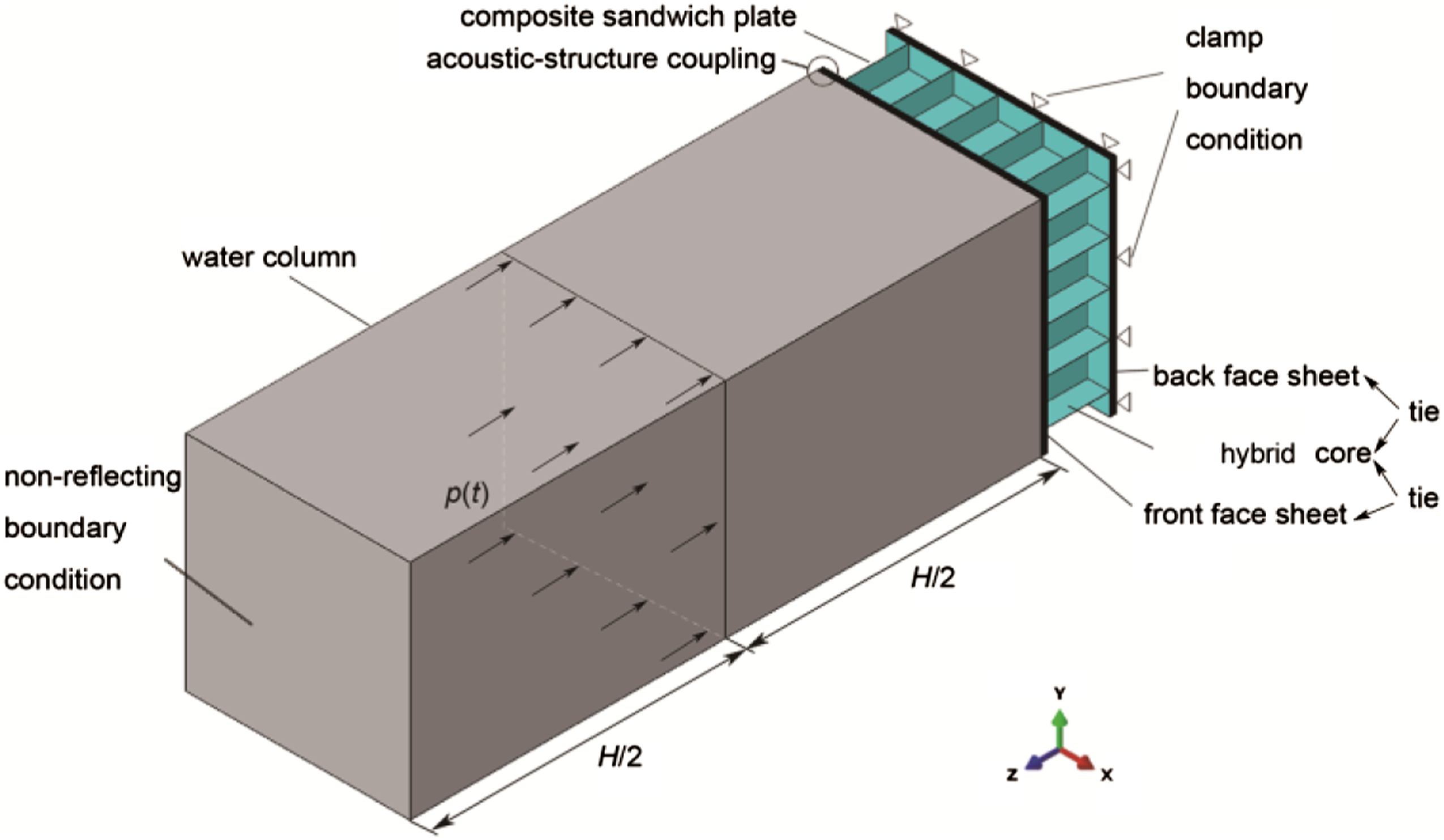
In order to reduce the influence of wave reflection in the water column caused by the dynamic response of the sandwich plates, thereby representing a semi-infinite condition, the water column was divided into two equal halves, each of 0.5 m in height direction. Acoustic pressure boundary condition described as equation (1) was applied to the plane separating the two halves of the water column, and a non-reflecting boundary condition was applied to the top surface of the water column.
In the FE model, the face sheets and the honeycomb of the sandwich were modeled using four-node shell elements with reduced integration which is notated as S4R in ABAQUS. The PMI foam fillers were modeled by eight-node linear brick elements with reduced integration (C3D8R). Furthermore, the core and the face sheets were bonded together with tie constrains at their interfaces.
The H = 1 m water column was modeled by eight-node linear acoustic elements with reduced integration, notated as AC3D8R in ABAQUS. The meshes of the water body along x and y axis are coincident with that of the front face. As for the meshes along z axis, the elements in the half close to the sandwich plate are cubic in size with a dimension of 5 mm; the mesh size of the elements along z axis of the half away from the sandwich plate is 10 mm. In order to realize the fluid-structure interaction (FSI), the top surface of the front face sheet and the water column were coupled together with tie constraint.
Constitutive model and damage law
Detailed description of the material models can be referred in Ref.29. Prior to damage initiation, the CFRP sheet was modeled as an orthotropic elastic material and the elastic response of the undamaged material is given by Ref.25
Damage initiation was modeled using Hashin’s failure criteria
30
which takes four failure modes into consideration, namely fiber tension, fiber compression, matrix tension, and matrix compression. After the damage initiates, a nonlinear stress versus strain response accompanies damage progression due to a progressive drop in three moduli (E1, E2, and G) with increasing strain which is given by
The PMI foam blocks are modeled as crushable foam using hardening curves obtained by the compression test on cubic foam samples. The compression process can be described as a linear elastic stage followed by a plastic hardening stage. In the plastic hardening stage, a phenomenological yield surface for a closed-cell foam was proposed by Deshpande et al.,
31
which is given by
Based on the yield stress in hydrostatic compression, the evolution of the shape of the yield surface can be described as
The water material is modeled in ABAQUS as an acoustic medium, which is used to model sound propagation problems and can be used in a purely acoustic analysis or in a coupled acoustic-structure analysis such as the calculation of shock waves in a fluid or noise levels in a vibration problem. The equilibrium equation for small motions of a compressible, inviscid fluid flowing through a resisting matrix material is as follows
The bulk modulus of an acoustic medium relates the dynamic pressure in the medium to the volumetric strain by
In this research, water was defined as an acoustic medium of density ρw = 1000 kg/m3 and bulk modulus Kw = 1.96 GPa, which means that the wave speed in water is
Validation of the numerical model based on experimental results
In order to verify the validity of the numerical model, experiments of the sandwich structure subjected to underwater explosion were performed. The layout of the experiments is shown in Figure 4. The dimension of the cubic water tank is 800 mm×300 mm×300 mm. Polymer foam sheets were attached on the inner walls to reduce the deflection of the shock waves. The structural parameters of the sandwich are as follows: the thickness of the face sheets is tf = 2 mm; the height of the core is hc = 45 mm; the spacing between honeycomb walls is lw = 30 mm; and the density of the filled foam is 52 kg/m3. The cylindrical explosives weighting 15 g is set 300 mm from the center of the front surface of the sandwich. The pressure on the center of the front face sheet was measured by a surface pressure sensor set on the surface of the front face sheet, and the displacement of the back face sheet was obtained by the displacement sensor set at the center of the back face sheet. Layout of the experiment for sandwich structures subjected to underwater explosion.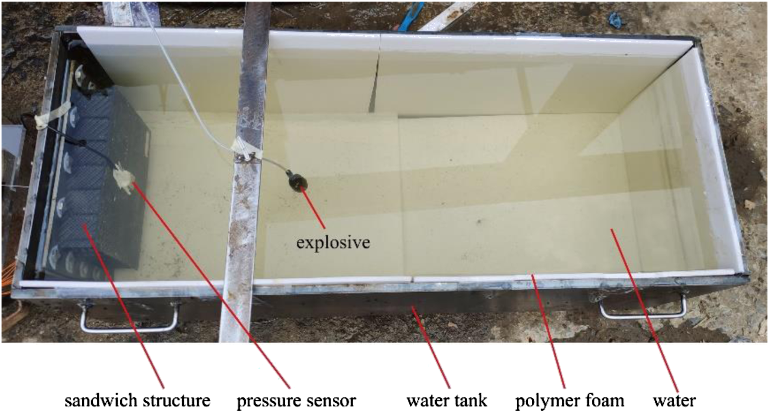
The pressure on the front face sheet and the central deflection of the back face sheet obtained from the experiments were compared with the numerical results, which are shown in Figures 5 and 6, respectively. Comparison of the pressure on the front face sheet between the experimental and FE results. Comparison of the central deflection of the back face sheet between the experimental and FE results.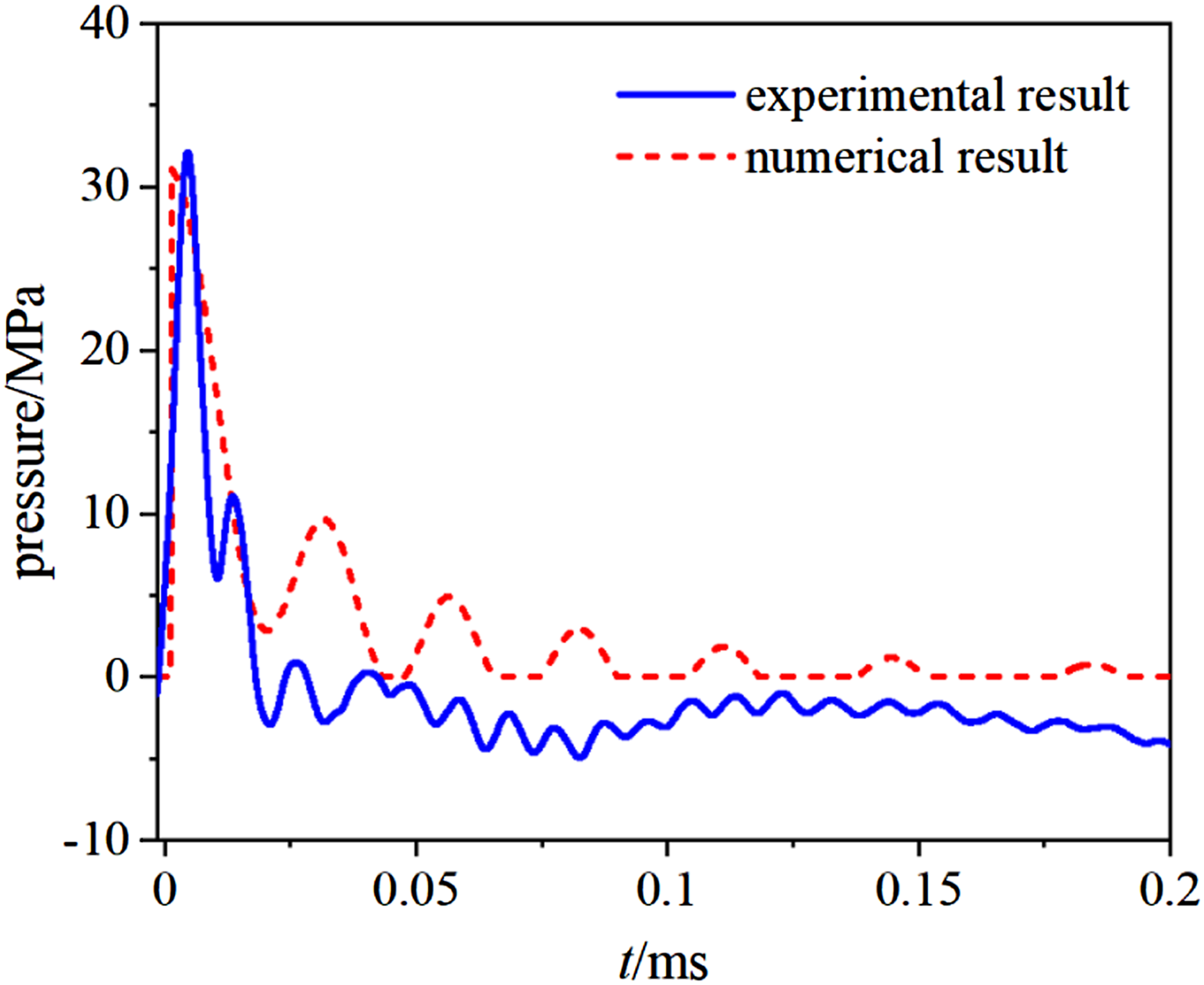
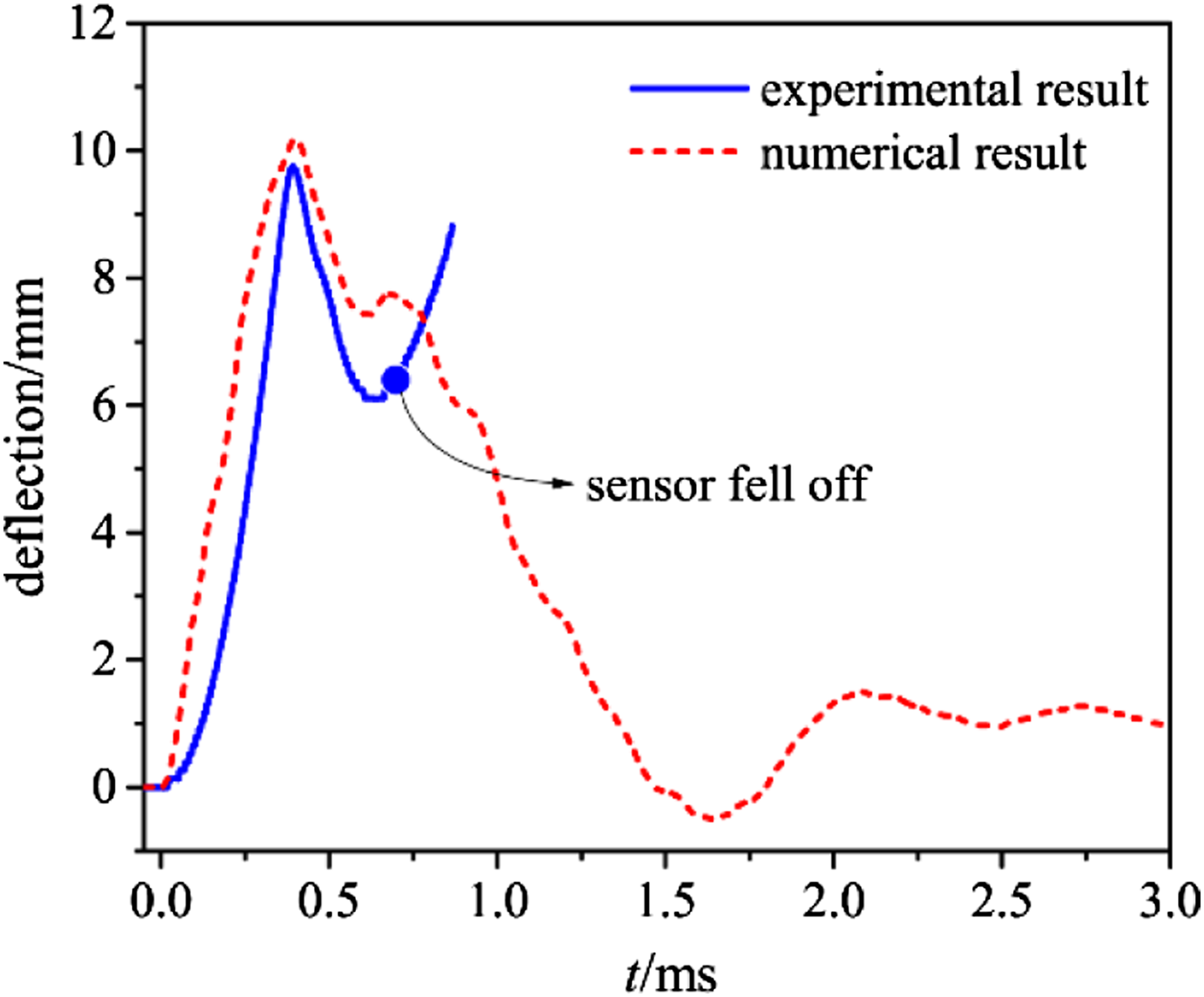
It can be seen from Figure 5 that the peak pressure and the decay property of the pressure on the front face sheet from the experiment and the numerical simulation agree well. The disparity of the pseudo-oscillations process after the pressure decreases to nearly zero is due to the effects of the wave deflection on the walls of the water tank, which was ignored in the numerical simulation but cannot be completely eliminated in the experiment. Additionally, we can see from Figure 6 that before the displacement sensor fell off from the back face sheet at about 0.7 ms during the experiment, the central deflection of the back face sheet collected from the experiment is in good agreement with the numerical result. The comparison between the FE and experimental results shows that the numerical model can accurately describe the dynamic response of the sandwich structure subjected to underwater shock waves.
Results and discussion
Deformation and energy absorbing process
Deformation process
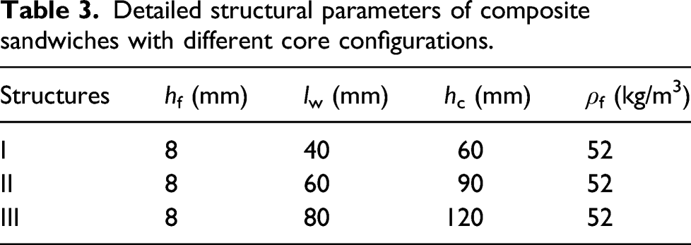
Taking the sandwich structure with hf = 8 mm,lw = 60 mm,hc = 90 mm, and ρf = 52 kg/m3 for instance, the deformation and energy absorption process of the sandwich subjected to underwater shock waves of which the initial pressure is p0 = 50 MPa were analyzed.
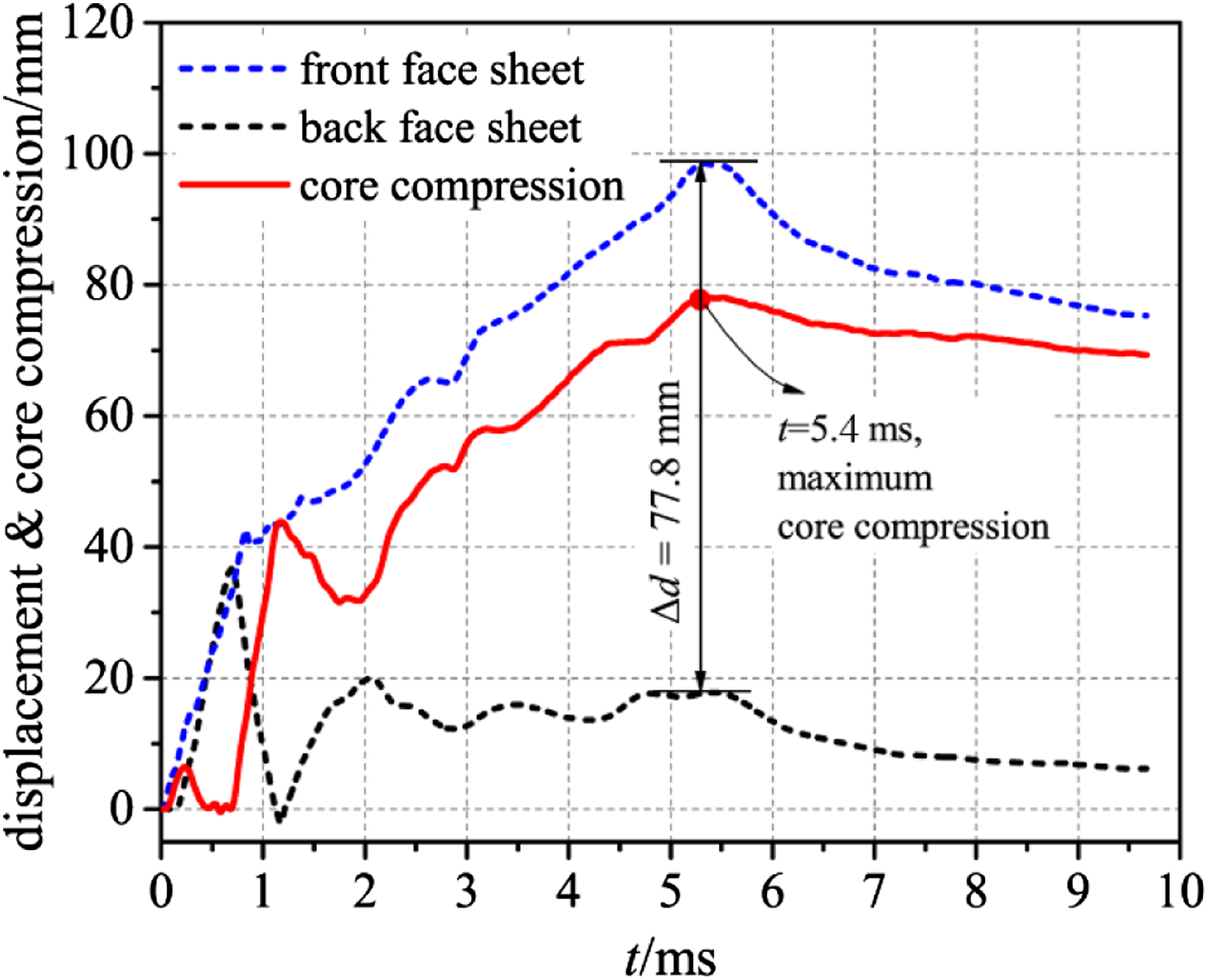
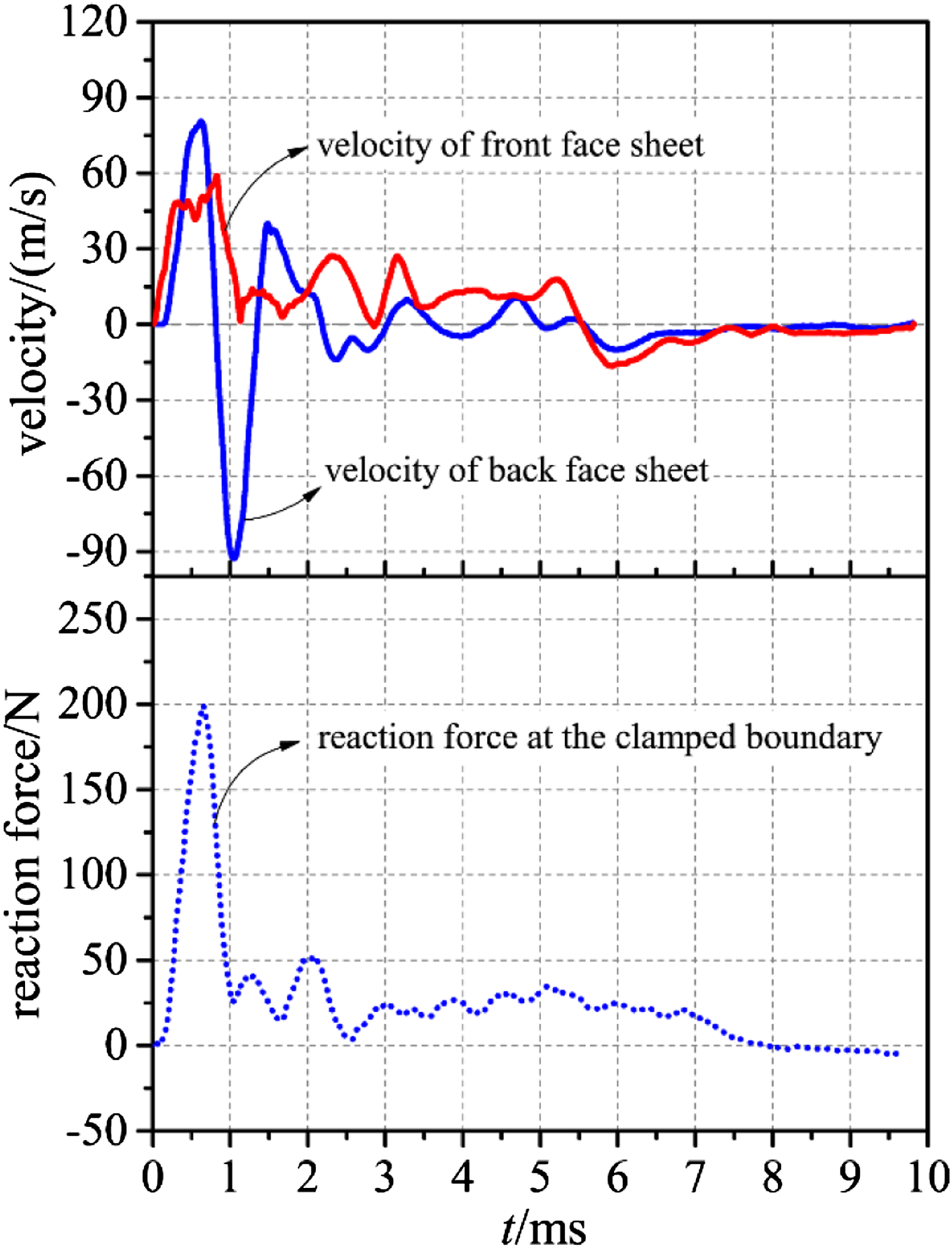
The deformation of the sandwich and its components at different moments is shown in Figure 7. t = 0 is the moment when the shock wave first arrives at the front face sheet. Additionally, the compression process of the core is shown in Figure 8 and time history of the face sheets and reaction force at the clamped boundary is shown Figure 9. We can see that the deformation process of the core can be broadly divided into the following five stages: As shown in Figures 6 and 7(I), the front face sheet began to accelerate once after the shock waves arrived at the front surface. The velocity of the front face sheet increased to about 45 m/s when t = 0.07 ms. The core was compressed under the action of the moving front face sheet. Meanwhile, due to the reaction force of the core, the increasing rate of the velocity of the front face sheet slowed down and the velocity reached its maximum value of about 60 m/s when t = 0.9 ms. Furthermore, the deflection of the back face sheet initiated after the stress wave traveling in the core arrived. It can be seen from Figures 8 and 9 that the velocity of the back face sheet increased rapidly to its peak value (about 80 m/s) and then began to decrease due to the reaction force from the clamped boundary. At the time t = 0.7 ms, the velocity of the back face sheet declined to 0 and the maximum central deflection of the back face sheet was reached (36 mm). We can also see from Figure 7(I) that the maximum core compression occurred at the edges of the structure. The back face sheet bounced back due to the structural stiffness, and the center of the core was further compressed. It can be seen from Figures 8 and 9 that the back face sheet started to accelerate reversely when t >0.7 ms. The velocity of the front face sheet declined on account of the reaction force of the core. Meanwhile, the central deflection of the back face sheet decreased gradually. When t = 1.2 ms, the back face sheet bounced to an ultimate position with the deflection of about −1.2 mm and the velocity of 0. After t > 1.2 ms, the velocity of the face sheets both fluctuated at a lower level with a positive value. In general, the velocity of the front face sheet is higher than that of the back face sheet, and thus, the compression of the core was further increased in a nearly linear mode. The velocity of the two face sheets equalized at the time t = 5.4 ms. Meanwhile, the core was condensed and the maximum core compression was approximately 77.8 mm. The velocity of the back face sheet continually decreased, which was close to 0 when t = 8 ms. Then the reaction force at the clamped boundary disappeared and no obvious deformation of the sandwich structure can be found anymore, indicating the cease of the dynamic response process of the sandwich. Deformation process of the sandwich structure subjected to underwater shock waves (hf = 8 mm, lw = 60 mm, hc = 90 mm, ρf = 52 kg/m3, p0 = 80 MPa, θ = 0.1 ms). Central displacement of face sheets and the compression process of the core (hf = 8 mm, lw = 60 mm, hc = 90 mm, ρf = 52 kg/m3, p0 = 80 MPa, θ = 0.1 ms). Velocities of face sheets and the reaction force at the clamped boundary of the back face sheet (hf = 8 mm, lw = 60 mm, hc = 90 mm, ρf = 52 kg/m3, p0 = 80 MPa, θ = 0.1 ms).
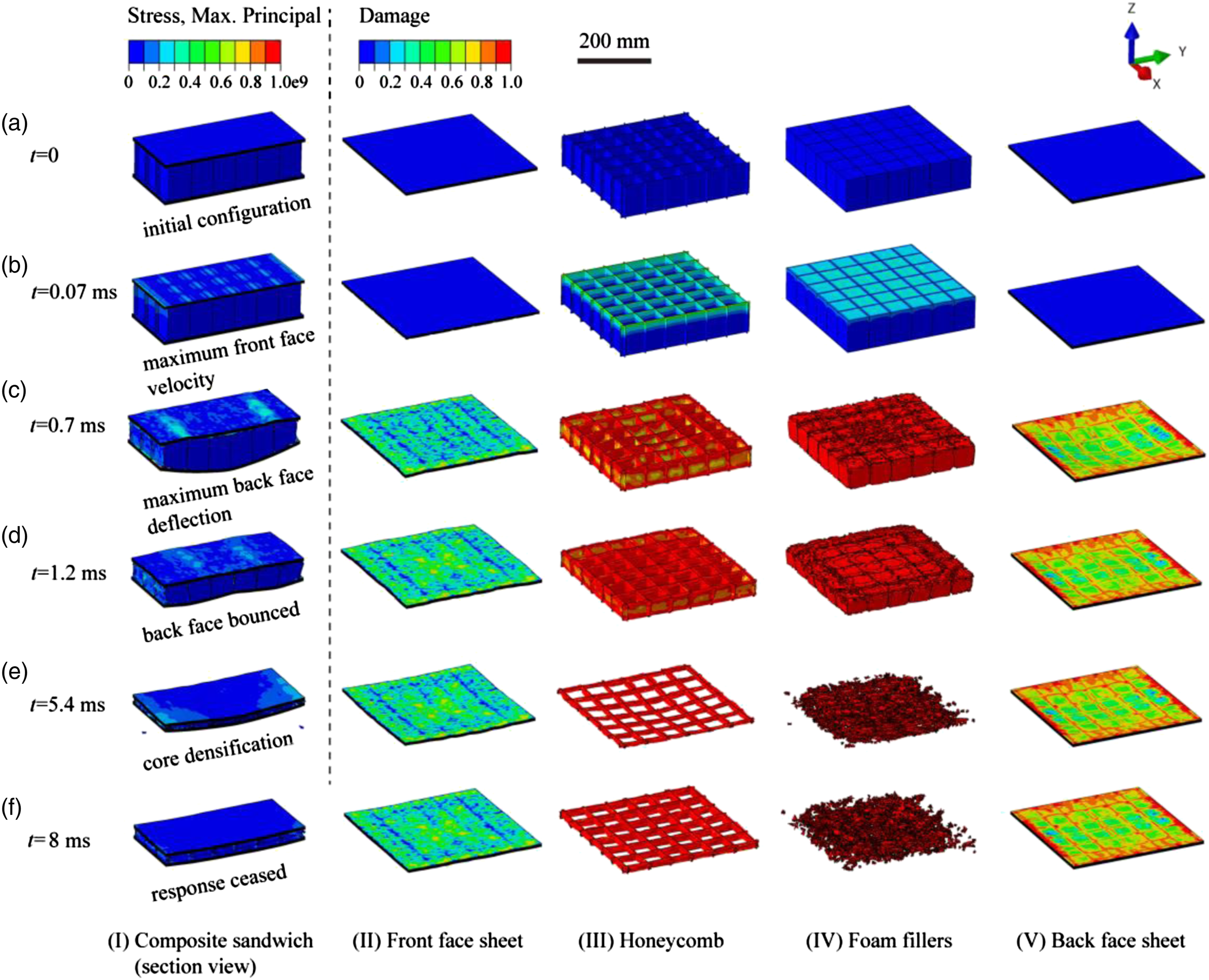
We proceeded to analyze the deformation and damage of different components of the sandwich during the shock wave loading process according to Figure 7(II)–(V). Figure 7(II) shows that the failure mode of the front face sheet was mainly local deflection. The damage first occurred at the contact position with the honeycomb wall and extended outwards during the loading process. It can be seen from Figure 7(III) that the compression of the honeycomb initiated from the side contacted with the front face sheet. First, the dynamic buckling of the honeycomb walls occurred. With the increase of the core compression, the honeycomb wall folded gradually and cracks appeared at interactions of honeycomb walls. The deformation process of foam fillers was similar with that of the honeycomb (Figure 7(IV)). The damage started to accumulate after plastic deformation occurred and then the foam fillers were squashed and fractured gradually. The damage in the back face sheet initiated during the core compression. Unlike the front face sheet, the deformation mode of the back face sheet was overall bending and severe damage can be found at the edges due to the clamped boundary conditions.
Energy absorbing process
The energy absorbing process of the sandwich structure subjected to underwater shock waves was proceeded to be analyzed. Figure 10 shows the energy absorbing process and the energy absorption ratio of the components in the sandwich. It can be seen that at the initial loading period, the energy absorption increased dramatically due to the severe deformation of the structure. After the back face bounced back at t = 1.2 ms, the evolution of the deformation and damage of the sandwich became insignificant so that the increase in the energy absorption slowed down. The energy absorption reached its maximum value of about 20,000 J when the core was totally compacted when t = 5.4 ms. Afterward, no obvious change can be found in the energy absorption. Energy absorption process of the sandwich structure and the energy absorption ratio of the components in the sandwich structure (hf = 8 mm, lw = 60 mm, hc = 90 mm, ρf = 52 kg/m3, p0 = 80 MPa, θ = 0.1 ms).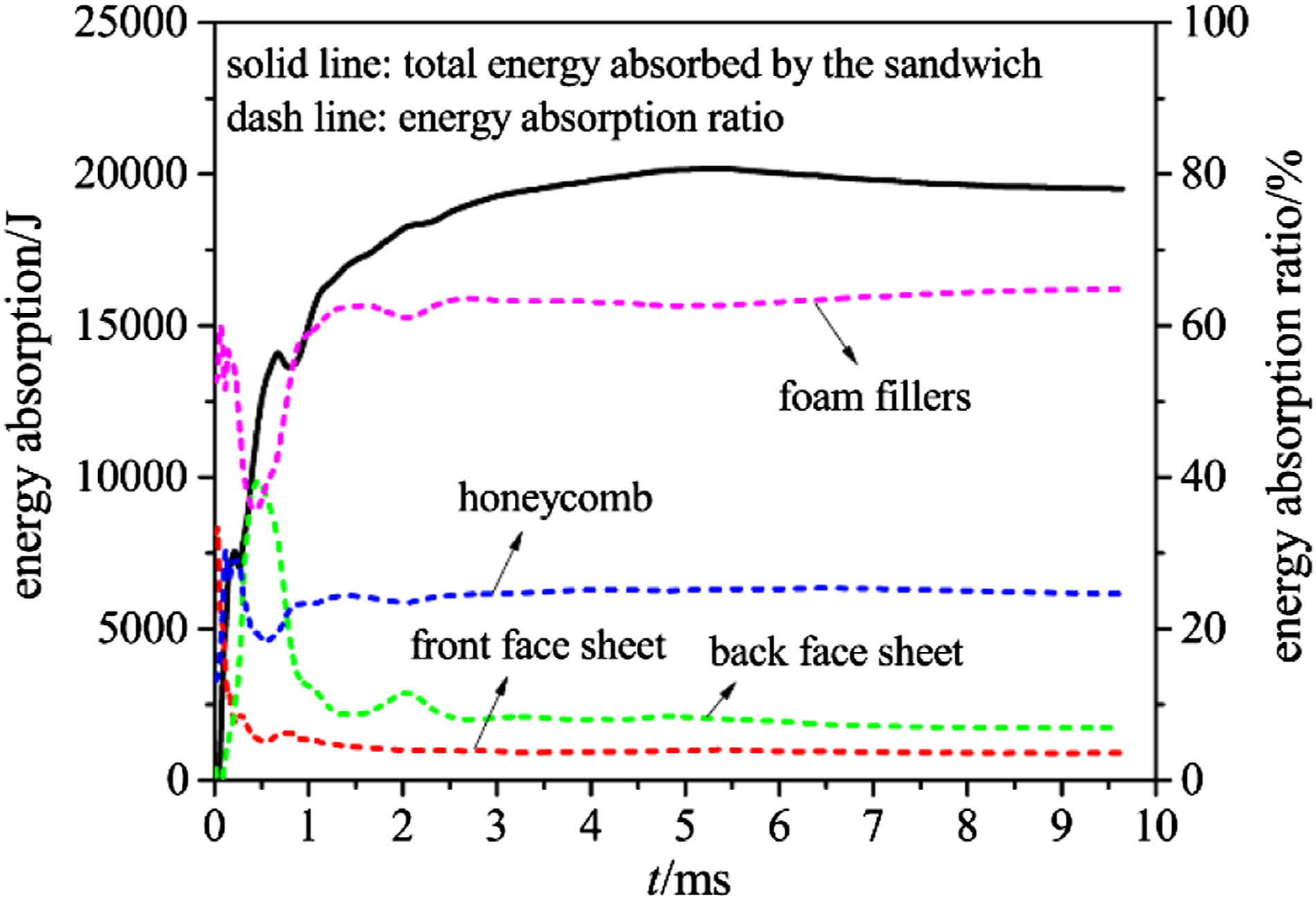
Comparing the energy absorption ratio of different components in the sandwich structure, it can be found that at the initial loading period, the energy absorption ratio of the front face sheet is relatively large due to its earlier deformation and damage initiation, but decreased rapidly to a lower level. As for the back face sheet, the energy absorption ratio increased rapidly during t < 0.7 ms due to its large overall bending deformation. However, most energy absorbed by the back face sheet during this time is elastic strain energy, which was promptly declined during the unloading stage of the elastic deformation when the back face sheet bounced back. Consequently, the energy absorption ratio of the back face sheet diminished gradually and reached a steady stage after t > 0.7 ms. The energy absorption ratios of the front and back face sheets were both lower than 10%. In comparison, the honeycomb and foam fillers were crushed during the loading of the shock waves, leading to a higher energy absorption ratio. The energy absorption ratio of the honeycomb was approximately 25% while that of the foam fillers was about 65%.
The time histories of the specific energy absorption for different components in the sandwich is shown in Figure 11. According to Figure 11(a) and (d), the energy absorption of the front and back face sheet is closely related to the deformation and damage of the structure. Damage in the front face sheet initiated immediately after the shock waves arrived, and thus its specific energy increased rapidly and reached to the peak value at t = 0.7 ms. Hence, no obvious evolution in the deformation and damage of the front face sheet can be found, and thus, the specific energy of the front face sheet kept on a nearly steady value of approximately 450 J/kg. Figure 11(d) shows that the time history curve of the specific energy for the back face sheet was similar to that of the central deflection of the back face sheet. The specific energy started to increase promptly after the central deflection initiated, and reached to the peak value at t = 0.7 ms when the ultimate deformation of the back face sheet was reached. Afterward, the elastic strain energy in the back face sheet declined due to the springback of the plate, leading to the decline of the specific energy. The deformation of the back face sheet ceased when t > 1.2 ms, and consequently, the specific energy absorption stabilized at a value of about 1000 J/kg. Time history of the specific energy absorption of different components in the sandwich structure: (a) front face sheet, (b) honeycomb, (c) foam fillers, and (d) back face sheet.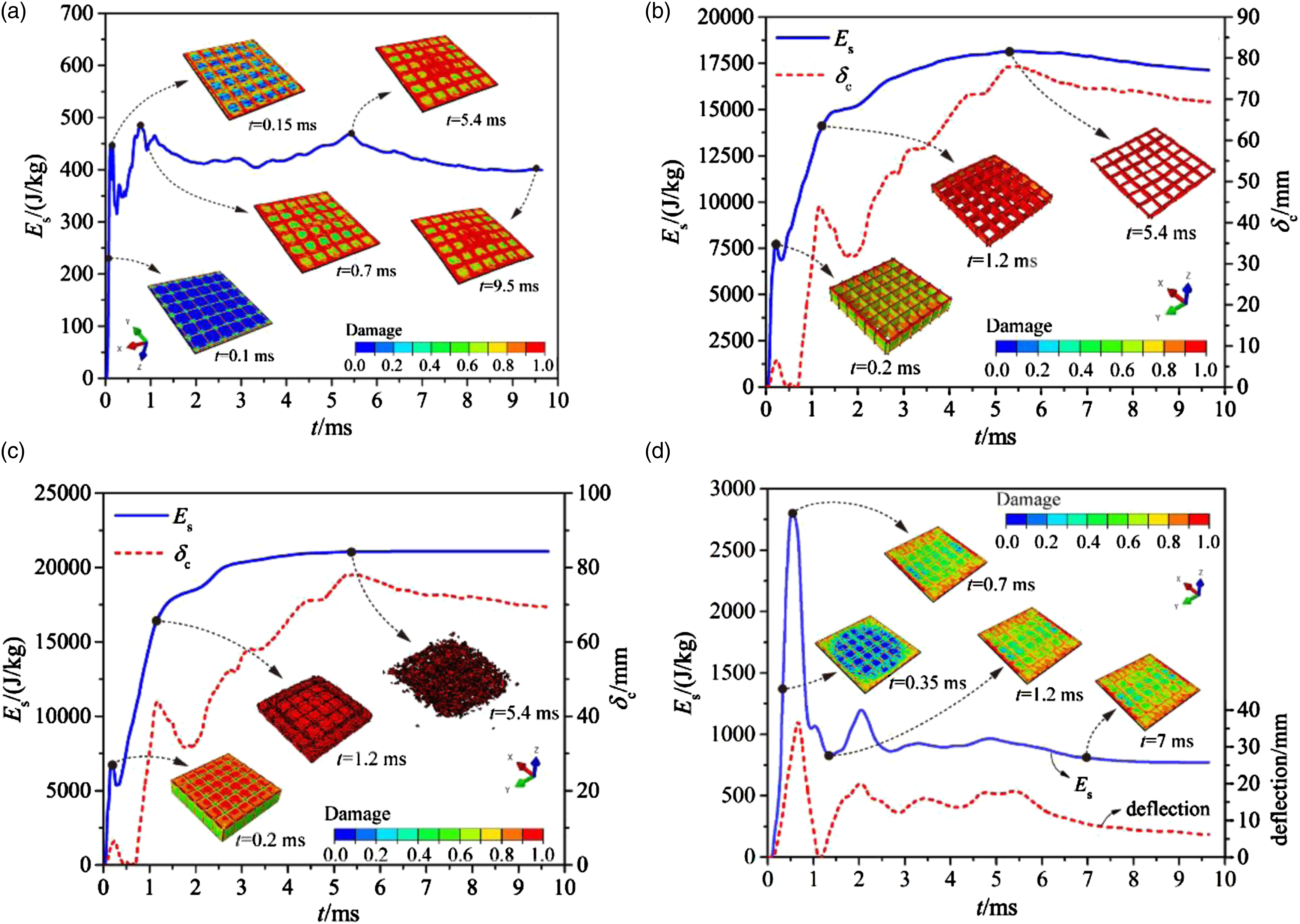
The time histories of the specific energy absorption of the honeycomb and foam fillers are similar, which are related to the core compression. It can be seen from Figure 11(b) that with the damage in the honeycomb accumulated rapidly with the loading process, the specific energy increased dramatically. The honeycomb was almost totally damaged when t = 1.2 ms under the compression, leading to the slowdown of the increase in the specific energy absorption. Complete compression of the core was reached when t > 5.4 ms, after which no obvious deformation and damage can be found in the honeycomb and thus the specific energy tended to be stable gradually at approximately 17,500 J/kg.
Figure 11(c) shows the time history of the specific energy absorption of the foam fillers. Similar to the honeycomb, the specific energy absorption increased rapidly with the damage accumulation in the foam (0 < t < 1.2 ms); the increase in the specific energy presented a slower trend when the foam were totally damaged (1.2 ms < t < 5.4 ms); and the specific energy tended to be stable after the full compression of the foam fillers (t > 5.4 ms). The specific energy absorbed by the foam fillers was the largest among all the components, which was approximately 20,000 J/kg.
Failure modes of the sandwich structure
Failure modes of the sandwich structure subjected to underwater shock waves with different initial pressures are shown in Figure 12. According to the contour of damage in the front face sheet shown in Figure 12, we can find that with the increase in the initial pressure, damage in the front face sheet became more severe and the damage area extended. The most severe damage area was located at the center of the front face sheet. When the initial pressure is low (p0 = 20 MPa), the failure mode of the front face was mainly local deflections. As the initial pressure increased, delamination between plies occurred in the front face sheet and the delamination failure became more severe as the initial pressure increased. Failure modes of the sandwich structure (hf = 8 mm, lw = 60 mm, hc = 90 mm, ρf = 52 kg/m3) subjected to underwater shock waves with different initial pressures: (a) p0 = 20 MPa; (b) p0 = 50 MPa; (c) p0 = 80 MPa; and (d) p0 = 100 MPa.
Damage in the foam fillers occurred at a small strain due to the low strength of the foam material, and the degree of crushing of the foam fillers increased with the increase in the initial pressure. There were two failure modes in the honeycomb, namely elastic buckling and plastic fracture. According to Figure 12(a), elastic buckling occurred in the honeycomb walls when the initial pressure was at a low level. Under this circumstance, the compression of the core was not significant and the damage degree of the honeycomb was quite low. The deformation of the honeycomb was mainly elastic bending, which can recover after the loading process. As the initial pressure increased to p0 = 50 MPa, the honeycomb was totally damaged, with hybrid failure modes including elastic buckling and folding deformation (Figure 12(b)). The deformation of honeycomb cannot recover when folding of honeycomb walls occurred. With the further increase in the initial pressure, the core compression continually increased and the honeycomb walls were totally fractured. The degree of the folding of honeycomb walls increased with the increase in the initial pressure.
According to the deformation of the back face sheet shown in Figure 12, the failure of the back face sheet was mainly overall bending. As discussed above, most deformation of the back face sheet was elastic; thus, the back face sheet can spring to its normal shape when the applied loading was removed. Although the maximum central deflection of the back face sheet increased with the increase in the initial pressure, the central deflection of the back face sheet when the applied loading ceased was at a quite low level (no more than 10 mm). Additionally, delamination between plies occurred in the back face sheet when the initial pressure increased to about 100 MPa and the locations of the delamination were mainly at the center of the back face sheet (Figure 12(d)).
Dynamic response of sandwich structures subjected to underwater shock waves with different initial pressures
Detailed structural parameters of composite sandwiches with different core configurations.
Back face deflection
The maximum deflection of the back face sheet when the sandwich was subjected to underwater shock waves is a key factor for evaluating the protective properties of the structure. The numerical results of the maximum deflection of the back face sheet for sandwich structures and mass equal laminates (dm) under different initial pressures are shown in Figure 13, including the theoretical predictions for sandwich structures based on the theoretical model by Fleck et al.
12
Numerical results of maximum deflection of the back face sheet of sandwich structures and mass equal laminates, including the theoretical predictions for sandwich structures.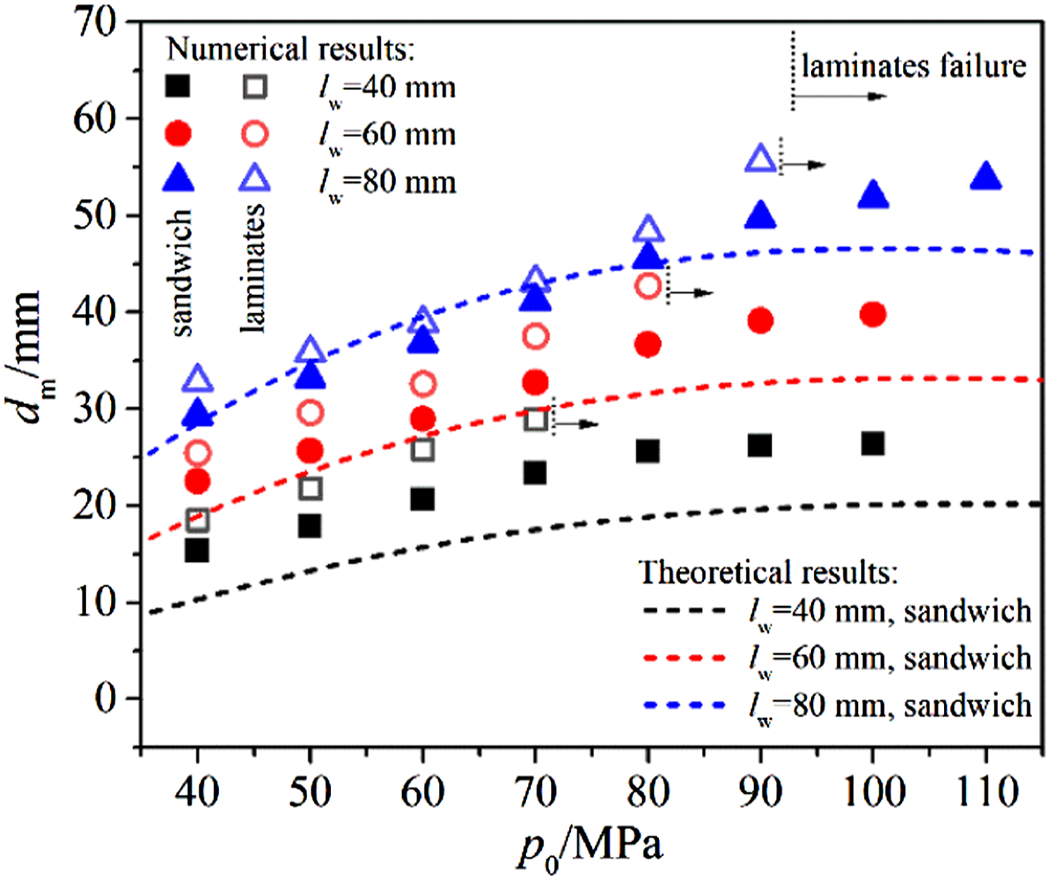
According to Figure 13, both the numerical results and theoretical predictions indicate that with the increase in the initial pressure, the maximum deflection of the back face sheet of the sandwiches presented an increasing trend. However, for the range of initial pressure in this research, the increasing rate of dm declined with the increase in the initial pressure. This is because with the increase in the initial pressure, the core structure absorbed more energy during the deformation, which can decrease the deformation of the back face sheet. Additionally, the comparison of the numerical results and theoretical predictions showed that they agree well when lw = 80 mm. However, disparity between the numerical results and theoretical predictions became larger with the decrease of lw due to the more obvious size effects in the numerical simulations for the sandwich with smaller lw. Overall, there is a reasonable agreement between the numerical results and theoretical predictions, providing that the theoretical model can accurately predict the maximum central deflection of the back face sheet. Comparing the central deflection of the back face sheet for three types of sandwich structures, it can be seen that with the increase in lw, the stiffness of the back face sheet decreased and, consequently, the maximum central deflection of the back face sheet increased.
The maximum central deflection of the back face sheet in the sandwich was further compared with the maximum central deflection of the mass equal laminate. It can be found that the maximum central deflection of the laminate also increased with the increase in the initial pressure and the increasing rate became larger as well. Under the condition with the same initial pressure, the maximum central deflection of the sandwich back face sheet was less than that of the mass equal laminate. Furthermore, the failure of the laminate occurred at lower initial pressure and the failure occurred earlier when the spacing between honeycomb walls decreased (lw = 40 mm, p0 > 70 MPa; lw = 40 mm, p0 > 80 MPa; lw = 40 mm, p0 > 90 MPa). For the range of initial pressure considered in this research, no failure occurred in the back face sheets of the sandwiches, indicating that the sandwich structure presented better protective properties than mass equal laminate plates.
Momentum transmission
The momentum transmission properties are important for evaluating the protective performance of the sandwich structures subjected to underwater shock waves. Generally, more momentum transmitted into the structure will lead to more severe deformation. The momentum transmission of the sandwich structure was obtained by numerical simulations and theoretical calculations and was compared with the momentum transmission of mass equal laminates.
According to calculation by Taylor,
32
momentum transmitted into the sandwich structure subjected to underwater shock waves can be calculated by
It can be seen that Taylor calculation only considered the mass of the front face sheet, but the effects of the core and back face sheet on the momentum transmission were neglected. Thus, it cannot accurately predict the momentum transmission of the composite sandwich structure (Figure 14). To take the effects of the core and back face sheet into consideration, associated mass was introduced Momentum transmission of the sandwich structures and mass equal laminates.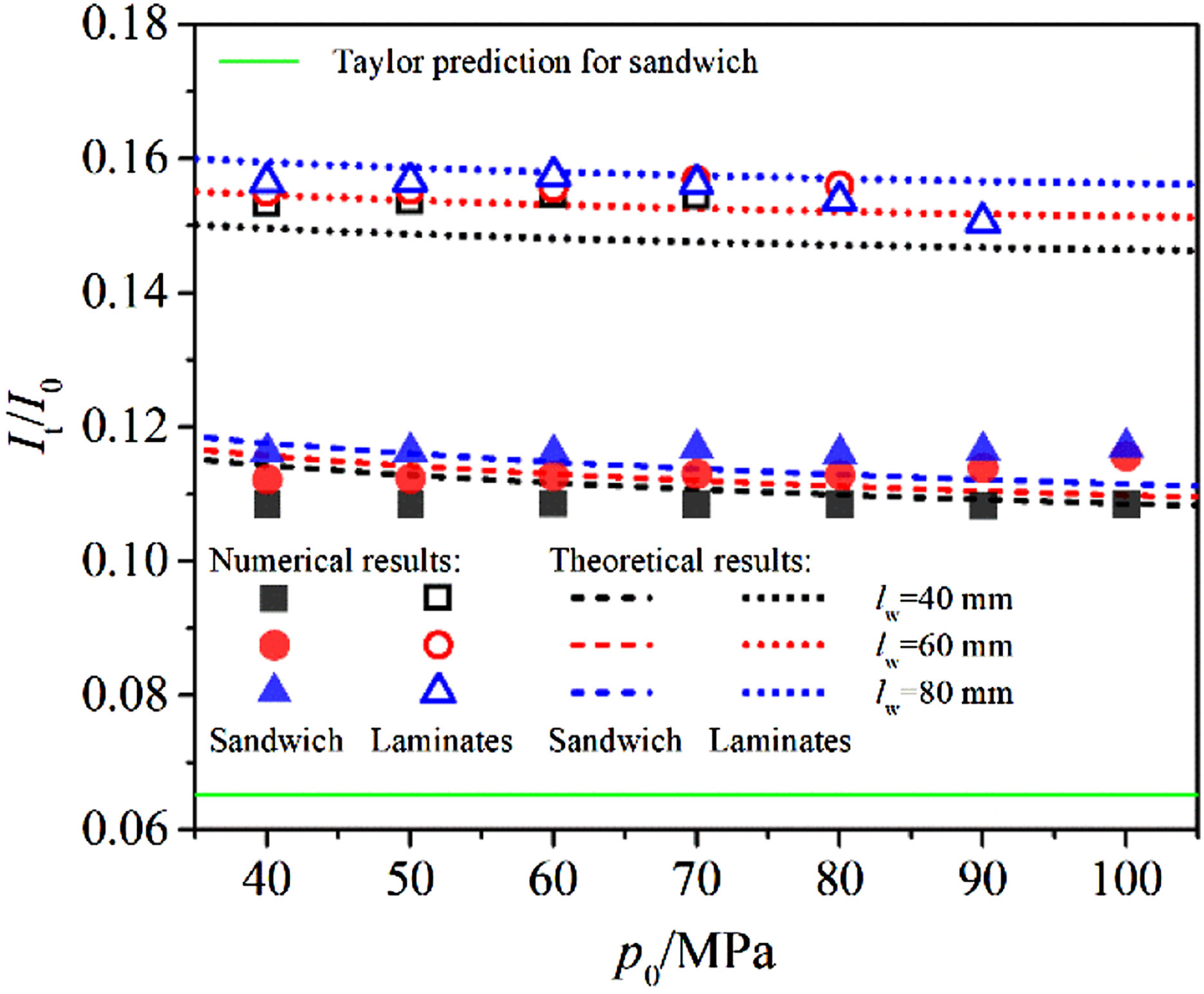
Then, the ratio of the momentum transmission can be written by
Figure 14 shows the comparison of the momentum transmission ratio versus initial pressure between the composite sandwiches and mass equal laminates. It can be seen that the modified theoretical model can accurately predict the momentum transmission of sandwich structures. Furthermore, we can see from Figure 14 that the ratio of momentum transmission for the three types of sandwich structures were nearly constant with the increase in the initial pressure. Additionally, with the increase in lw, the ratio of momentum transmission increased slightly. But there was no obvious disparity between these three sandwiches in the ratio of momentum transmission, which was approximately 0.11. Meanwhile, the comparison of the ratio between the sandwiches and mass equal laminates showed that the ratio of momentum transmission for the laminates was about 35% higher than that for the sandwiches, which provides the superior protective performance of the composite sandwich structure subjected to underwater shock waves.
Core compression
The energy absorption of the sandwich structure is largely dependent on the deformation and compression of the core. In general, the energy absorption increases with the increase in the core compression. Figure 15 shows the core compression of three sandwiches under different initial pressures from which can be seen that the numerical results agreed well with the theoretical predictions. The numerical results indicated that when the initial pressure was low (p0 < 40 MPa), the core compressions of different sandwich structures were all not obvious. With the increase in the initial pressure, the core compression increased gradually until the core densification was reached, after which the core compression remained constant with the increase in the initial pressure. The densification ratio of the core (the ratio of the core compression at densification to the core height) for different sandwich structures were all approximately 90%. According to the theoretical calculations, the threshold initial pressure for core densification of sandwich structures with lw = 40 mm, 60 mm, and 80 mm were about 72 MPa, 78 MPa, and 83 MPa, respectively. Comparing the core compression of different sandwiches, it can be found that under the same initial pressure, the core compression increased with the increase in the spacing between honeycomb walls. This is due to the increase in the core height with the spacing between honeycomb walls. However, the specific core compression (the ratio of core compression to the core height) for different sandwich structures was close. Core compression of sandwich structures under different initial pressures.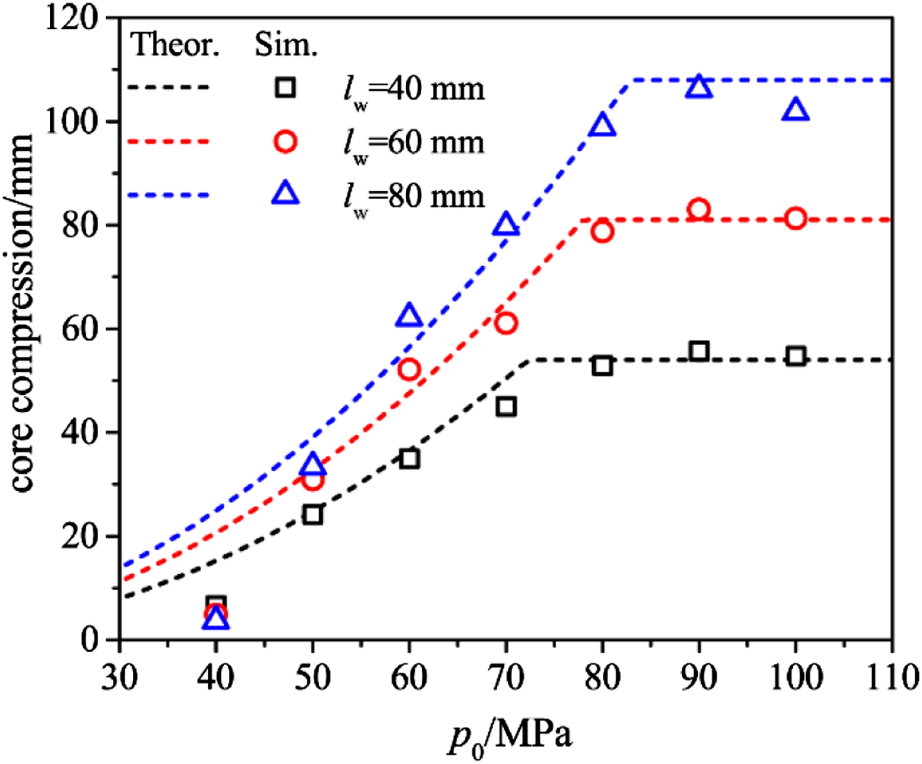
Energy absorption
In order to describe the energy absorption properties of the sandwich with considering the structural deformation, the energy absorbing efficiency (ηE) was defined as the ratio of the total specific energy absorption of the sandwich structure to the maximum deflection of the back face sheet
The energy absorbing efficiency of three sandwiches and mass equal laminates were obtained by the numerical simulation, which is shown in Figure 16. Meanwhile, the specific energy absorption of the sandwiches is shown in Figure 17. Energy absorbing efficiency of the sandwich structures and mass equal laminates under different initial pressures. Specific energy absorption of the sandwich structures under different initial pressures.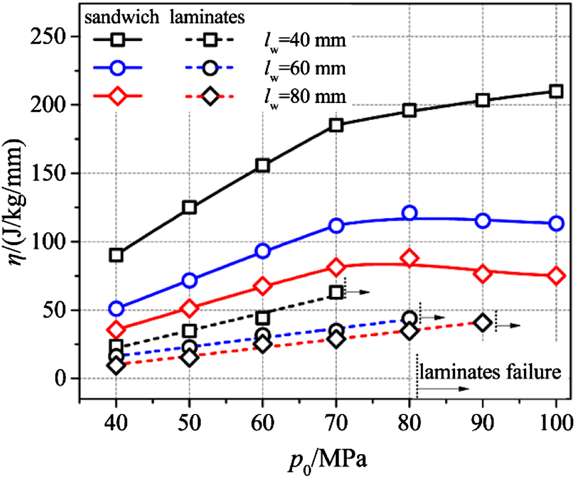
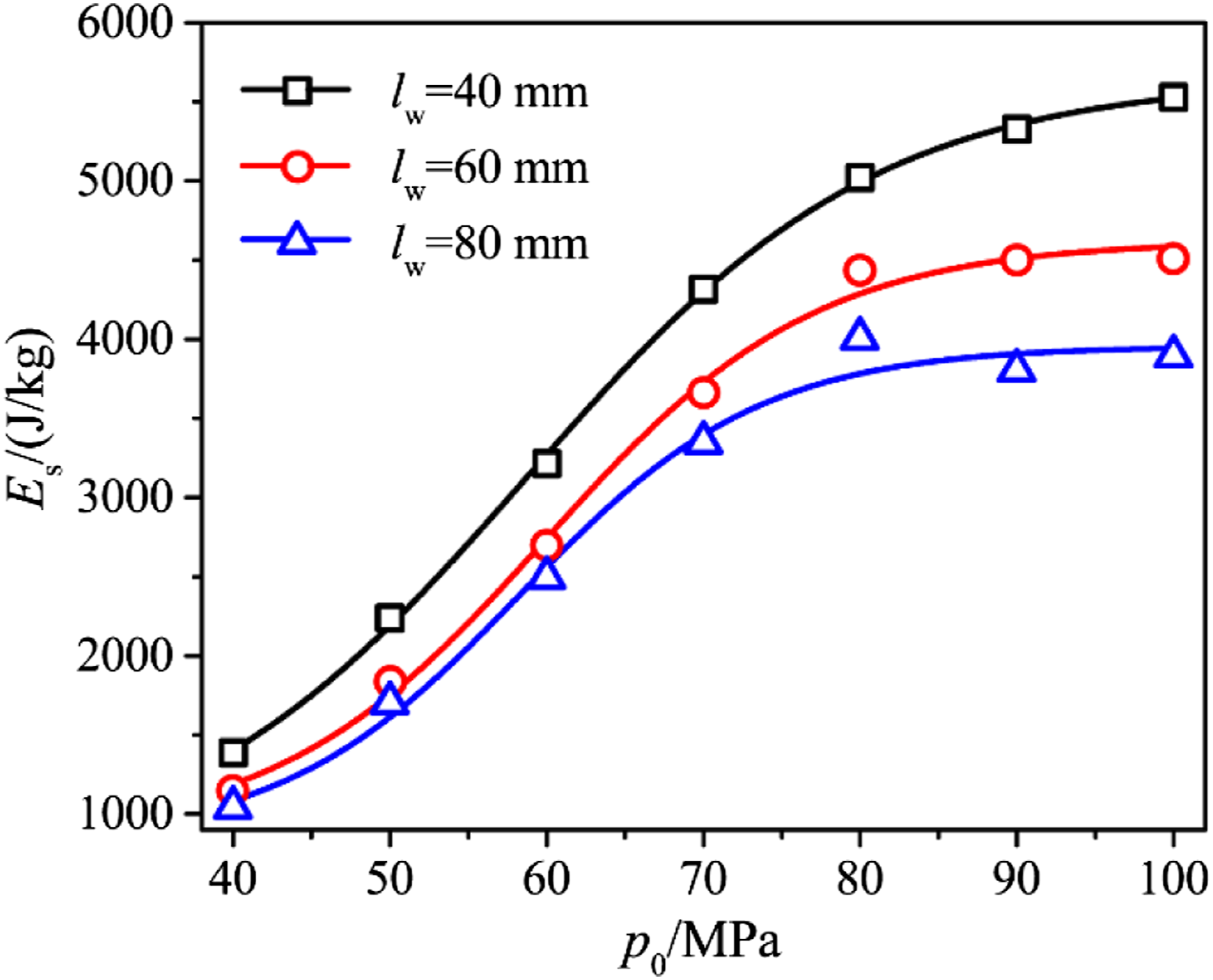
It can be seen from Figures 16 and 17 that the variation of the energy absorbing efficiency with the initial pressure can be divided into two stages based on the compression degree of the core. Specifically, before the core was completely compacted (p0 < 70 MPa), the specific energy of the core increased with the core compression; thus, the energy absorbing efficiency of the sandwiches increased in a nearly linear mode as the initial pressures increased; after the core was completely compacted (p0 > 70 MPa), the core compression stopped increasing, and thus the increase in the specific energy of the sandwich slowed down (Figure 17). However, the deformation of the back face sheet continued, leading to a decrease in the increasing rate of energy absorbing efficiency of the sandwich. Additionally, for sandwiches with lw = 60 mm and 80 mm, the energy absorbing efficiency presented a slight declining trend.
Comparison of the energy absorbing efficiency between three different sandwiches showed that the energy absorbing efficiency decreased with the increase in the spacing between honeycomb walls due to the lower specific energy absorption of sandwiches with larger lw (Figure 17). Meanwhile, the deformation of the back face sheet increased as lw increased, resulting that the sandwich with lw = 40 mm was superior in energy absorption to the other two sandwiches. Furthermore, the comparison of the energy absorbing efficiency between the sandwiches and mass equal laminates shows that the energy absorbing efficiency of the laminate kept increasing linearly until the structure failed, and the energy absorbing efficiency of the laminate is far smaller than that of the sandwich, which provides the advantage of the sandwich structure in energy absorption.
Comparison of the protective properties between sandwich structures with different cores against underwater shock waves
Structural parameters of sandwich structures with different core configurations.

Numerical simulations of above sandwiches subjected to underwater shock waves with initial pressure ranging from 10 to 150 MPa were carried out and the protective properties were compared.
Comparison of core compression
Core compression of different sandwiches subjected to underwater shock waves with varying initial pressures are shown in Figure 18, in which εc represents the core compression ratio, that is, the ratio of the maximum core compression to the initial core height. Comparison of core compression between sandwich structures with different core configurations.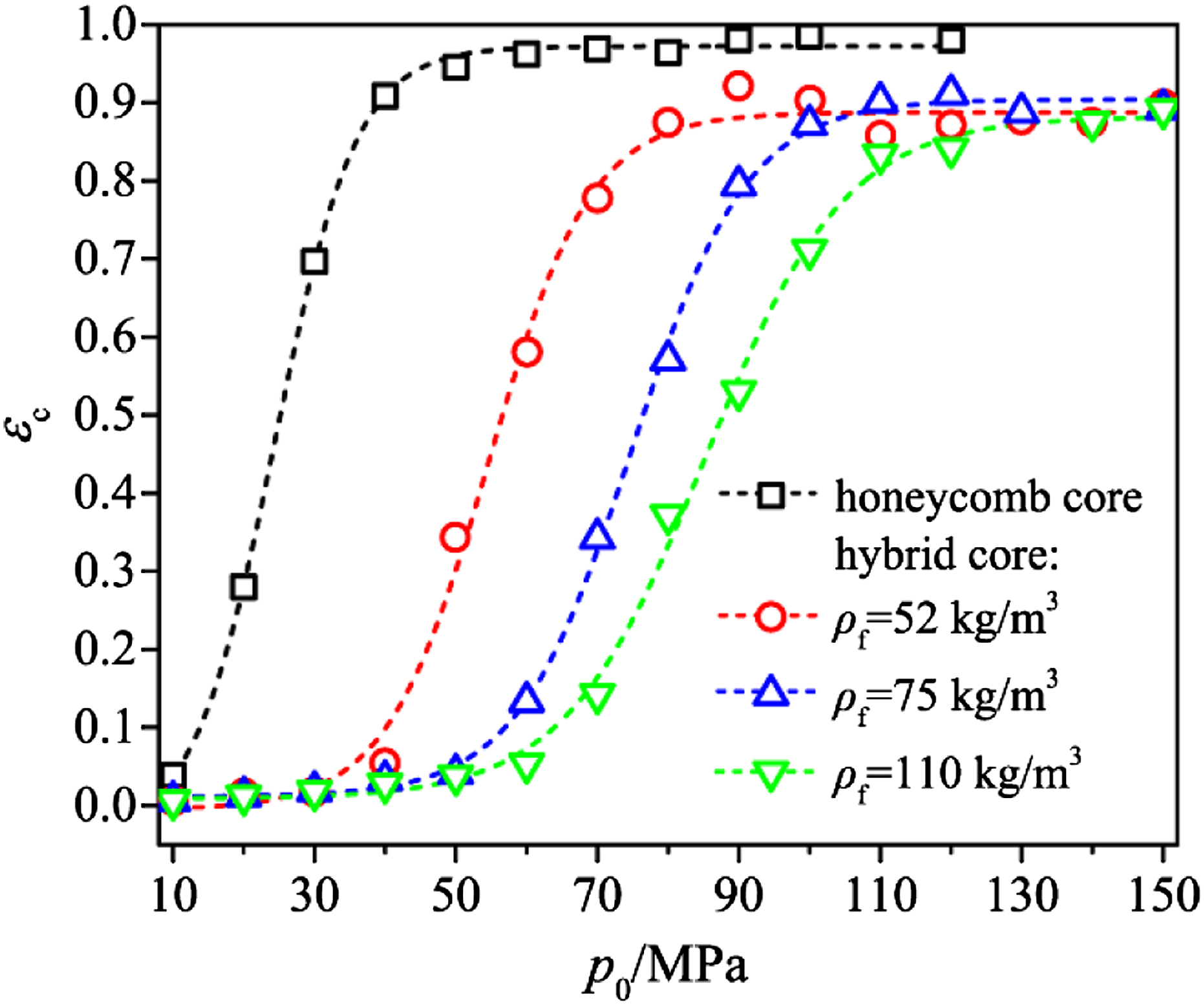
It can be seen from Figure 18 that for sandwiches with different core configurations, there was critical initial pressure of the shock waves for core compression initiation. Specifically, if the initial pressure was lower than the critical value, the core compression was small enough to be neglected. However, if the initial pressure was higher than the critical value, the core compression increased rapidly in a nearly linear mode until the core was totally compacted. For the sandwich with the empty honeycomb core, the critical initial pressure for core compression initiation was lower than 10 MPa, while the critical initial pressures for hybrid-cored sandwiches with foam densities of 52, 75, and 110 kg/m3 were around 40, 50, and 60 MPa, respectively. It can be seen that the hybrid core was harder to be compressed compared to the empty honeycomb core due to the enhancement of the foam fillers on the strength. Furthermore, the compression ratio of the empty honeycomb core increased rapidly with the increase in the initial pressure until the honeycomb core was completely compacted when p0 = 50 MPa, and the maximum compression ratio of the empty honeycomb was close to 1. In comparison, the increasing rate of the compression ratio for hybrid cores decreased with the increase in the foam density. For hybrid cores with foam densities of 52 kg/m3, 75 kg/m3, and 110 kg/m3, the initial pressure when the core was completely compacted were around 80 MPa, 110 MPa, and 140 MPa, respectively. Additionally, the maximum compression ratio of the hybrid core was approximately 0.9.
With respect to sandwiches subjected to underwater shock waves, the front and back face sheets would contact with each other if the core was totally compacted, which could increase the deformation and damage of the structure and was against the protective performance. The honeycomb core was completely compacted after the initial pressure exceeded 50 MPa, which indicated that the honeycomb-cored sandwich structures were not suitable for underwater shock waves with initial pressure over 50 MPa. The hybrid-cored sandwich structures with higher core strength are more suitable for protection against underwater shock waves with higher initial pressure.
Comparison of maximum central deflection of the back face sheet
The maximum deflection of the back face sheet of sandwiches (dm) with different core configurations is shown in Figure 19. Comparison of maximum deflections of the back face sheet of sandwich structures with different cores.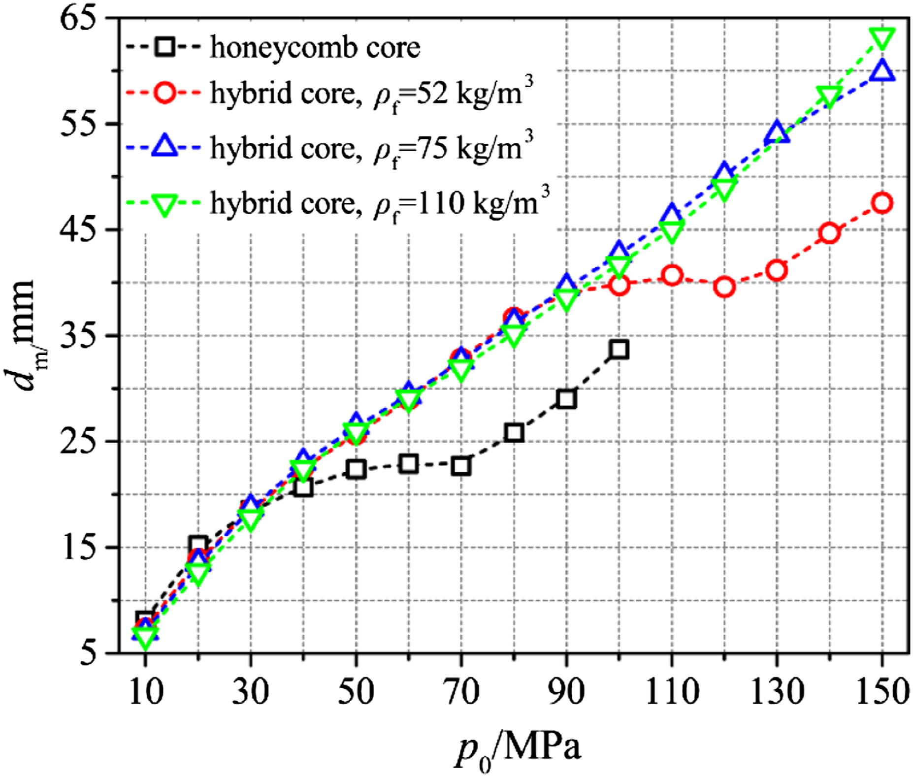
It shows that when the initial pressure is lower than 40 MPa, there is no obvious difference in dm between different sandwiches. But in general, the deflection of the back face sheet for the sandwich with the empty honeycomb core was the largest and the deflection of the back face sheet for sandwiches with hybrid cores declined with the increase in the foam density. When p0 > 40 MPa, the empty honeycomb core was completely compacted and the deflection of the back face sheet stopped increasing with the increase in the initial pressure because the fully compacted core absorbed most of the energy. When p0 > 70 MPa, the energy absorbing capacity of the empty honeycomb reached its limit and thus the deflection of the back face sheet began to increase again. By contrast, for sandwiches with the hybrid core, the deflection of the back face sheet continuedly increased with the increase in the initial pressure. However, the increasing rate of the deflection decreased slightly due to the energy absorption of the core. Additionally, there was no obvious difference in the deflection of the back face sheet between the three sandwiches with hybrid cores. When p0 > 90 MPa, the deflection of the back face sheet for the hybrid-core sandwich of which the foam density is 52 kg/m3 first showed the similar regulation of that of the sandwich with empty honeycomb core. Meanwhile, the deflection of the back face sheet of the hybrid-cored sandwiches with foam densities of ρf = 75 kg/m3 and 110 kg/m3 kept increasing with the initial pressure when p0 < 150 MPa.
Overall, the deflection of the back face sheet for sandwich structures subjected to underwater shock waves increased with the initial pressure of the shock waves. Under the shock waves with the same initial pressure, there is no obvious difference in deflection of the back face sheet for four types of structures. However, due to the difference in the core strength, the core compression of different sandwiches showed varying regulations, leading to disparities in changing laws of deflection of the back face sheet for different sandwiches after the core was fully compacted.
Comparison of the transmitted momentum
The transmitted momentum versus initial pressure of shock waves for sandwiches with different core configurations is shown in Figure 20. It can be seen that the momentum transmitting ratio (It/I0) for different sandwiches stayed nearly stable with the increase in the initial pressure. Comparing the momentum transmitting ratio between different sandwiches, it can be seen that the momentum transmitting ratio of the honeycomb-cored sandwich was the smallest, while for the hybrid-cored sandwich, the momentum transmitting ratio increased with the increase of the foam density. Based on the previous theoretical calculations, the pressure applied on the front face sheet is equal to the sum of the incident wave (positive), reflected wave (positive), and the rare wave (negative). The core with lower strength can provide lower reaction force for the front face sheet. Thus, the front face sheet can obtain higher velocity under the shock wave with the same initial pressure, which can generate a rare wave with higher amplitude, resulting in a lower pressure applied on the front face sheet and, therefore, a lower momentum transmitting ratio as well. Specifically, the momentum transmitting ratio for the honeycomb-core sandwich structure was around 0.093. For hybrid-core sandwiches with foam densities of ρf = 52 kg/m3, 75 kg/m3, and 110 kg/m3, the momentum transmitting ratio were approximately 0.115, 0.118, and 0.124, respectively. Comparison of the transmitted momentum of sandwich structures with different core configurations.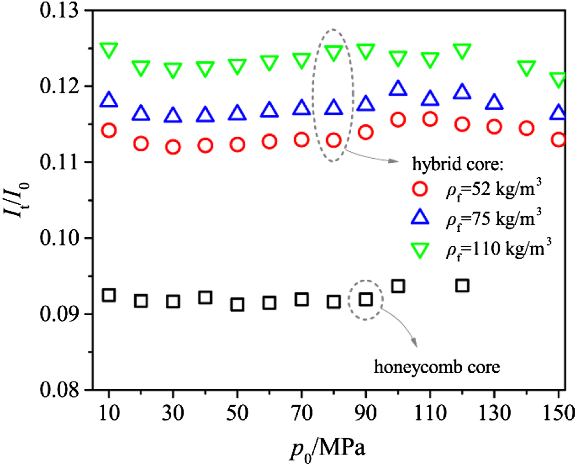
Comparison of energy absorption
Comparison of the specific energy absorption and energy absorbing efficiency of four sandwiches are shown in Figures 21 and 22, respectively. It can be seen that with the increase of the initial pressure of shock waves, the deformation of the structures became more severe; thus, the specific energy absorption increased accordingly. When the initial pressure of the shock waves was low (p0 ≤ 30 MPa), there was no significant compression for the hybrid core; thus, the specific energy absorption of the hybrid-cored sandwich was smaller than that of the honeycomb-cored sandwich. The energy absorbing efficiency of the sandwiches declined with the increase in the core strength. As the initial pressure increased, the increasing trend of specific energy absorption of the honeycomb-cored sandwich became moderate due to the complete compaction of the core, while the specific energy absorption of hybrid-cored sandwiches presented a larger increasing trend due the increase of the core compression. The honeycomb-cored sandwiches gradually lost the superiority in specific energy absorption. The energy absorbing efficiency for honeycomb-cored sandwiches stopped increasing gradually and was exceeded by the energy absorbing efficiency for hybrid-cored sandwiches. When p0 > 60 MPa, the honeycomb was completely compacted, then the deflection of the back face sheet increased significantly with the increase of the initial pressure, while there was no obvious change in the increase of the specific energy absorption. Consequently, the increase in the energy absorbing efficiency of honeycomb-cored sandwiches ceased and stabilized at about 70 J/kg/mm. For p0 ≤ 80 MPa, the specific energy absorption and energy absorbing efficiency for hybrid-cored sandwiches declined with the increase of the foam density, indicating that the hybrid-cored sandwiches with lower-density foam fillers had superiority in energy absorbing property. However, when p0 > 80 MPa, the hybrid core that the density of foam fillers is 52 kg/m3 was fully compacted; thus, the increase in the specific energy absorption ceased and the energy absorbing efficiency presented a slight decreasing trend. By contrast, the specific energy absorption and energy absorbing efficiency of hybrid-cored sandwiches with foam densities of 75 and 110 kg/m3 kept increasing while p0 > 80 MPa. When p0 > 100 MPa, the deformation and damage of the face sheets for the hybrid-cored sandwich with foam density of 52 kg/m3 became more severe, leading to a significant increase in the specific energy absorption of the sandwich. Thus, the specific energy and energy absorbing efficiency began to increase again. However, the increasing rate of the energy absorbing efficiency was smaller than that when p0 < 80 MPa because the increase in the deflection of the back face sheet with the initial pressure was more significant in this stage. For other two types of hybrid-cored sandwiches, similar changing laws can be found during the increase of the initial pressure. Comparison of specific energy absorption of sandwich structures with different core configurations. Comparison of energy absorbing efficiency of sandwich structures with different core configurations.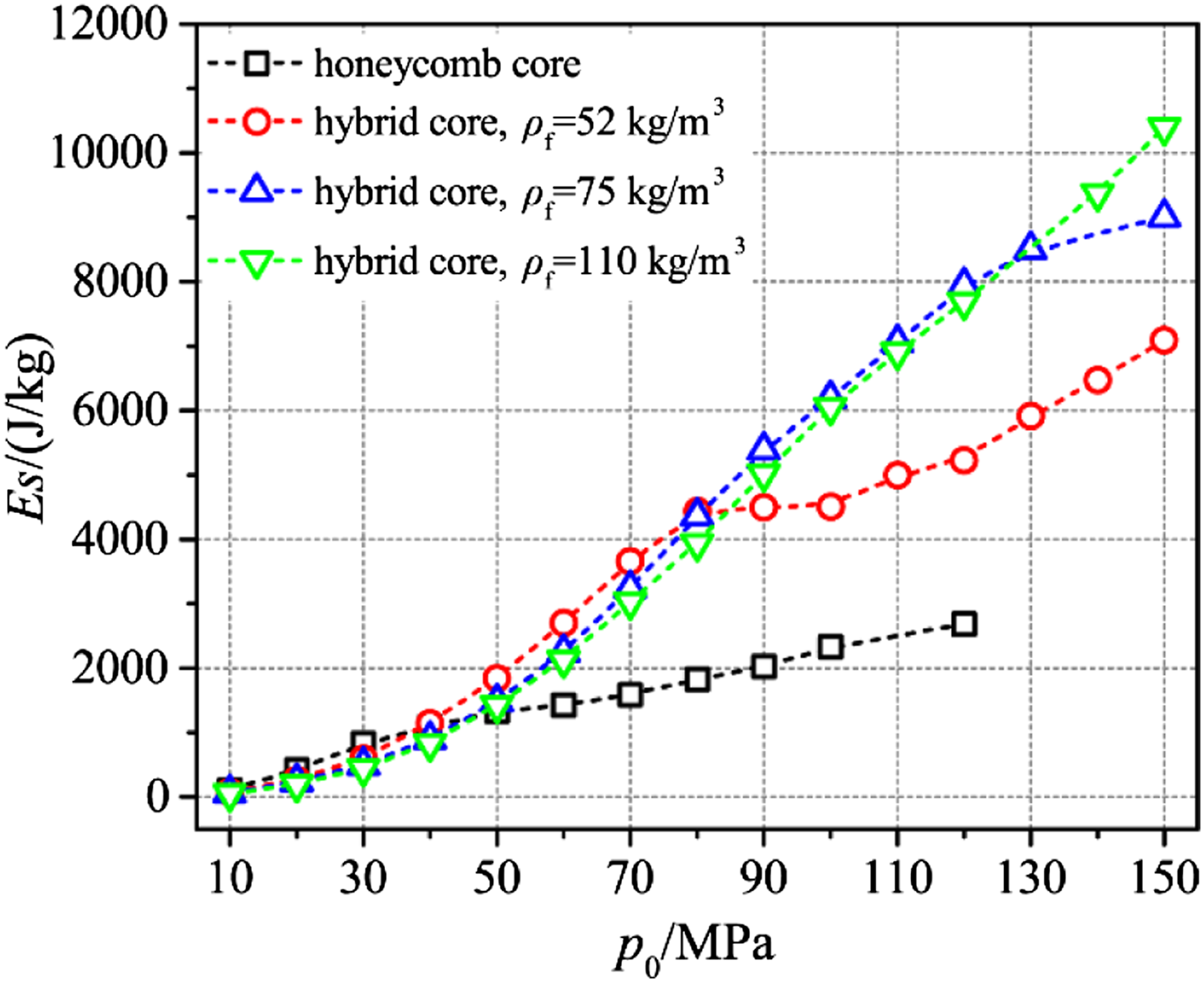
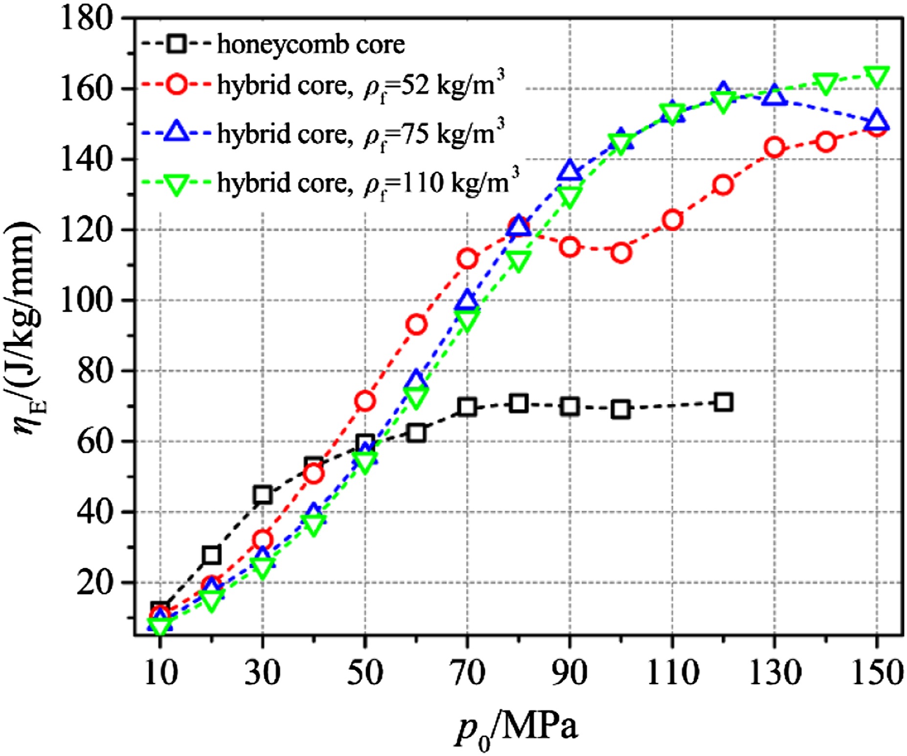
Overall, under shock waves with small initial pressure, sandwiches with the honeycomb core presented better energy absorbing performance than hybrid-cored sandwich structures. However, for shock waves with large initial pressure, the energy absorbing performance of sandwiches with hybrid cores was more excellent.
In conclusion, compared to the hybrid-cored sandwich, the honeycomb-cored sandwich effectively reduced the transmitted momentum and the deformation of the back face sheet. However, due to the low strength and poor compressive performance of the honeycomb, the honeycomb-cored sandwich was not energy efficient while subjected to underwater shock waves with high initial pressures, providing that the honeycomb-cored sandwich was only suitable for conditions with low-initial-pressure shock waves. In comparison, sandwiches with hybrid cores performed well in both conditions for underwater shock waves with low and high initial pressures. It showed that sandwiches with hybrid cores have a wider application scope and are more suitable for protective structures against underwater shock waves.
Conclusions
The dynamic response of the composite sandwich structures with the honeycomb-foam hybrid core subjected to underwater shock waves was numerically analyzed. The failure modes, deformation, energy absorbing properties, and momentum transmitting properties of the sandwich structures subjected to underwater shock waves with different initial pressures were discussed. The main conclusions are as follows: The numerical results of the dynamic response of the sandwiches against underwater shock waves agree well with the experimental results, providing that the FE model can accurately describe the dynamic response of the sandwiches with hybrid cores. The composite sandwich structures with the honeycomb-foam hybrid core have better protective performance than mass equal laminated when subjected to underwater shock waves. When the initial pressure of the shock waves was low, the front face sheet presented a failure mode of local deflection, while the back face sheet showed an overall bending deformation. With the increase of the initial pressure, delamination occurred in the face sheets. The foam fillers in the core were crushed during the action of the shock waves and the crushing degree of the foam fillers increased with the increase of the initial pressure. As for the honeycomb, the failure modes could be pure elastic buckling or folding deformation, or hybrid failure modes including elastic buckling and folding deformation, with the variation of the initial pressure of the shock waves. The composite sandwich structures with hybrid cores performed well in both conditions for underwater shock waves with low and high initial pressures, providing that sandwich structures with hybrid cores have a wider application scope and are more suitable for protective structures against underwater shock waves.
Footnotes
Acknowledegements
We thank the colleagues in our lab for the assistance with the experiments.
Declarations competing interests
The author(s) declared no potential conflicts of interest with respect to the research, authorship, and/or publication of this article.
Funding
The author(s) disclosed receipt of the following financial support for the research, authorship, and/or publication of this article: This research is supported by National Natural Science Foundation of China (Grant Nos. 11972197 & 12102199).
