
Abstract
In this study, an attempt was made on the AA2024 alloy based hybrid nanocomposites reinforced with different weight percentage of SiC and B4C particles to investigate their physical and machinability characteristics including surface morphology. The Material Removal Rate (MRR), Surface Roughness (SR) of the nanocomposites machined by various machining processes namely Abrasive Water Jet (AWJ) machining, Wire Electrical Discharge (WED) machining and Computer Numerical Controlled (CNC) turning processes were studied comparatively. The machined surface formed by the each machining process is examined and its surface quality was discussed for each hybrid nanocomposite. Results show that the hardness is increased to 101.6 BHN from 179.4 BHN, when 2 wt.% of B4C and SiC particles is added to AA2024 matrix. Observed from the results that the addition of 2 wt.% of B4C and SiC particles produces the highest porosity of 3.36% for nanocomposite samples. The experimental results revealed that the addition of particulates in to the matrix reduces the MRR and increases SR. MRR results showed that hybrid nanocomposites machined by AWJ technique has minimum MRR of 0.0221 mm3/min. The surface roughness of the nanocomposites machined with AWJ process was 3.2 µm and increased to 6.81 µm for the AA2024-B4C-SiC hybrid nanocomposites machined with CNC process.
Introduction
The use of particle reinforced Metal Matrix Composites (MMCs) have been increasing owing to their improved mechanical behaviors, such as specific stiffness and specific strength in the defense, automotive and aerospace industries. The fabrication techniques and reinforcement properties have a vital role in deciding the physical and mechanical behavior of composites.1–4 The addition of reinforcements into the matrix material enhances the properties of materials, but the particle content decides the mechanical properties of the composites. However, the excessive inclusion of particles leads to the porosity and also the particle agglomeration within the metal matrix. 5 The nano scaled reinforced particles added composites have eradicated the drawback of MMCs. 6 SiC, Al2O3 and B4C are widely used reinforcements in the composite materials because of their high wear resistance.7–9
Few methods are adopted for fabricating the composite materials. Among these methods, the powder metallurgy method is one of the most suitable methods for the fabrication of metal matrix composites. It avoids the chemical reaction between the matrix and reinforcement phases while retaining the parent metal morphology. Moreover, this method allows more than one reinforcement phase to be added to the metal matrix structure. 10 Powder Metallurgy consists of three steps; mixing metal and ceramic particles, compacting composite powders in a die at room temperature and then heating in a controlled atmosphere furnace to create a bond between the particles.11–13
Although MMCs show excellent mechanical, physical and thermal behaviors, important problems arise from use in practice due to processing costs and poor machinability. In addition, the machining of MMCs by traditional machining methods has some disadvantages such as short tool life, subsurface damage and poor surface quality.14–18 For these reasons, researchers and manufacturers have drawn attention to the use of non-traditional machining methods such as AWJ, WED and CNC.19–21 The AWJ machining method provides high-quality surface yields thanks to its properties such as high-speed water, high-speed sand abrasives sent on the workpiece and high-pressure impact erosion. In addition, since this method does not cause problems such as thermal distortion, heat affected zone and re-layer formation, it is one of the most suitable methods for machining MMCs.22,23 The WED method has provided an important innovation, especially in mold production, thanks to its ability to precisely create complex shapes on hard materials. The sparks that occur in WED machining are continuously produced by the tool electrode (wire) and the gap formed in the part to be removed from the workpiece. With the control of the wire movement, the desired shape and accuracy of the work material can be achieved.24–26 On the other hand, CNC turning is multi-axis, more accurate, automated machining, no skilled labor required and low cost compared to traditional turning. Tool materials made of ceramics and high-speed steels wear rapidly due to hard reinforcement particles during the machining of MMCs and therefore hard MMCs cannot be processed effectively. However, most researchers have noted that polycrystalline diamond (PCD) tools can be used to machine hard MMCs due to their long tool life. It is stated in the literature that the PCD tool is harder than ceramic particles such as B4C, SiC and Al2O3, and does not have any tendency to chemical reaction with the workpiece.27–29
Researchers generally works the effect of reinforcement content, size and type and matrix type on the machining quality properties such as surface roughness, surface hardness and also tool wear. Mohankumar and Kanthababu 30 calculated the depth of cut formed during AWJ machining of composites reinforced with 5, 10 and 15 wt.% B4C by volume to an aluminum-based metal matrix. They found that the highest depth of cut in parameters such as 340 g/min mass flow rate, 80 mesh size, 60 mm/min cross velocity and 200 MPa water pressure. Shandilya et al. 31 studied the quality of the material removal rate by changing the WED machining parameters (pulse on and off time, voltage and wire feed speed) of SiC reinforced aluminum matrix composites. They stated that when the parameters of voltage, wire feed speed and pulse duration increased, Ra and MRR data increased in direct proportion. Kesarwani et al. 32 machined aluminum matrix composite and hybrid composites produced by stir casting method, in CNC turning at the constant parameters of 0.1 mm/dev feed rate, 500 r/min cutting speed and 0.5 mm depth of cut. They revealed that the MRR values of aluminum matrix composites were at least 43% higher than the base alloy. In addition, they recorded the surface roughness (Ra) of the hybrid composite as minimum 2.23 µm. Prakash Rao et al. 33 investigated the machining properties of fly ash (5, 10 and 15%) reinforced Al6061 MMCs, which they produced by stir casting method, on CNC turning with carbide cutting tool. They stated that there was an increase in the cutting force with the increase of the feed rate and the increase in the reinforcement content and the rolling of the edge increased the cutting force.
As a member of the ceramic particle reinforced composites family, Al matrix hybrid composites are one of the most important engineering materials due to lightness, high specific strength, good thermal conduction, easy production and low cost. The addition of hard ceramic particles to the Al matrix structure significantly improves the mechanical strength and wear resistance but significantly worsens the machining ability and machining becomes more difficult than that of metal and their alloys. Considering that Al matrix hybrid composites are used more and more every day and new types of machining methods are emerging, the machining properties of hybrid composites should be revealed comprehensively. Moreover, metal matrix composites containing B4C have the highest hardness compared with other composites and they cause more brittle fracture during the machining process. Considering the research conducted in the literature, although these previous efforts, there is still a need to explain and discuss the machining properties of Al metal matrix hybrid composites for fully explore their potentials. Therefore, the purpose of this work was to (a) fabricate nano-sized B4C and SiC ceramic reinforced AA2024 matrix hybrid nanocomposites by powder metallurgy method; (b) study the effect of reinforcement content on the MRR, SR and surface morphology of the hybrid nanocomposites during the machining process and (c) investigate the effect of different machining methods such as AWJ, WED CNC on the machining characteristics on the AA2024-B4C-SiC hybrid nano composites.
Experimental work
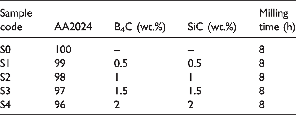
AA2024 powders (Gündoğdu Exoterm Company, Turkey) are used as matrix and SiC and B4C (Wacker Ceramics, Germany) particles at varying weight percentage are selected as reinforcements for making the hybrid composite materials. The chemical composition of AA2024 alloy is shown in Table 1. AA2024-B4C-SiC hybrid nanocomposites were fabricated by powder metallurgy method by adding reinforcement amounts of 0, 1, 2, 3, and 4 wt.% by weight. Hybrid nanocomposite powders were milled in a dry ball milling at a speed of 400 r/min, a ball: powder ratio of 10: 1 and for 8 h in argon atmosphere. Methanol (2 wt.%) was used as the process control agent during the dry ball milling process. The nanocomposite powders were compressed in a uniaxial MSE brand hot press device at 500 MPa for 40 min and sintered at 560°C for 3 h under vacuum atmosphere (pressing and sintering were done in the same device). The produced samples have dimensions of 80 × 10 × 6 mm (Figure 1). The sintering temperature was reached at a speed of 30°C/min, and the samples were cooled outside the furnace after sintering. The composition and milling time are mentioned in Table 2.
The chemical composition of AA2024 alloy in weight percent. 12
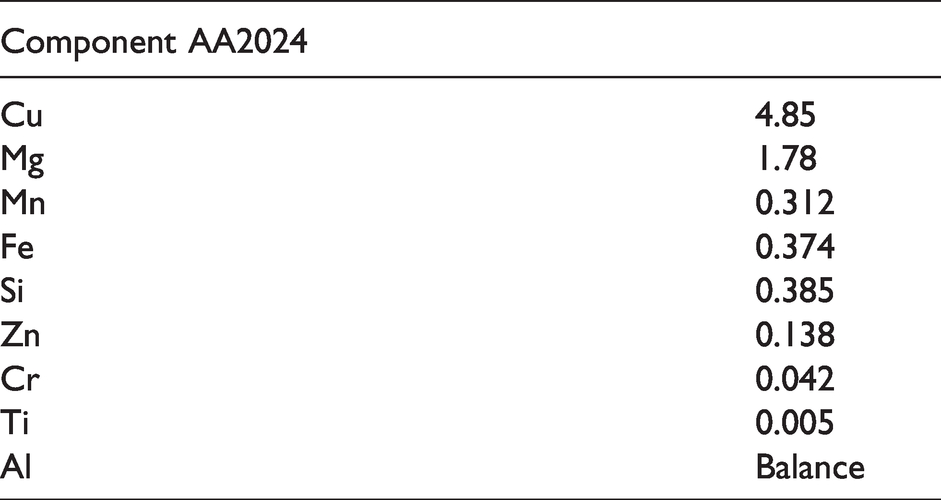
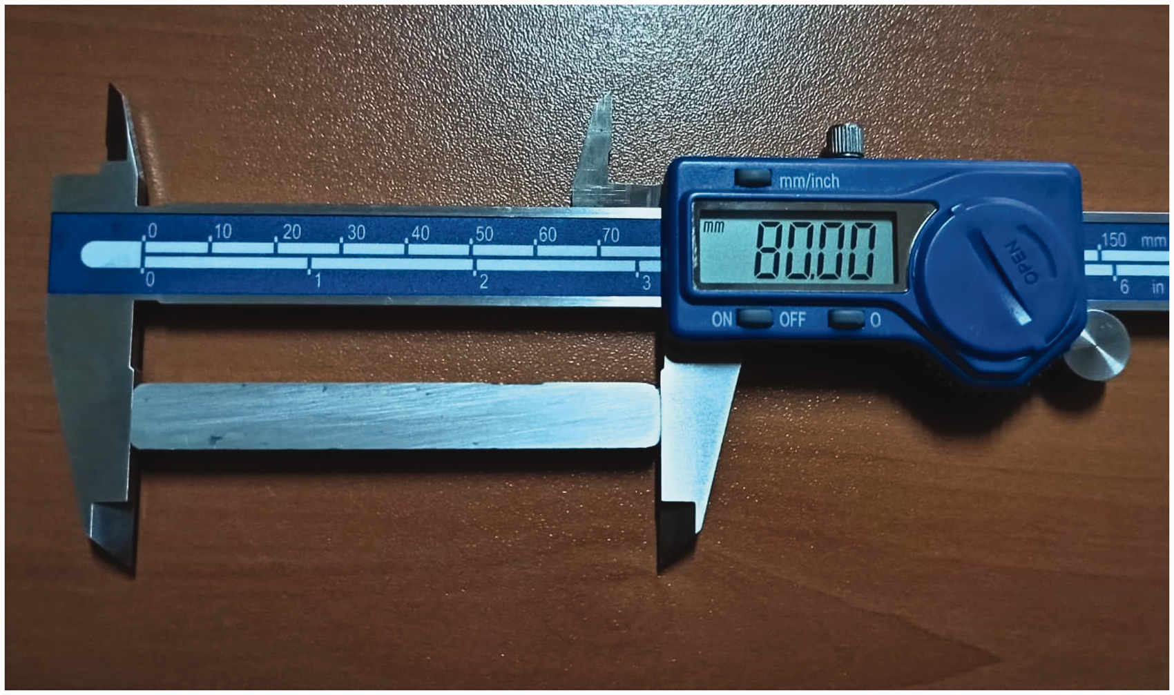
Image of AA2024-B4C-SiC hybrid nanocomposite sample produced by powder metallurgy method.
Classification of AA2024 alloy and AA2024-B4C-SiC hybrid nanocomposites.
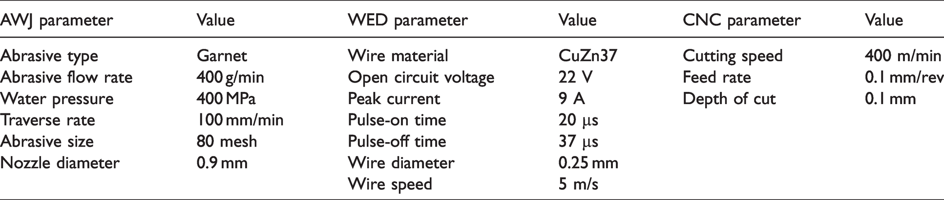
Archimedes’ method was used to determine the density of AA2024-B4C-SiC nanocomposites. The hardness of hybrid nanocomposites was obtained with Brinell hardness in ASTM E10 standard. The hardness was tested by utilizing a hardness tester (Innovatest Nemesis 9000 model) with load of 31.25 kg and dwell time of 10 s. For density and hardness tests, five measurements were taken in each sample to provide the repeatability of the test results. The composite sample is machined by using different machining techniques; Abrasive Water Jet (AWJ) machining, Wire Electrical Discharge (WED) machining and Computer Numerical Control (CNC) machining processes. The machining parameters used in the experimental work are presented in Table 3. The Material Removal Rate (MRR) for each machining process was determined by using equation (1). The machined surface is further explored to measure the surface roughness (Ra, Rz and Rmax). The surface roughness values of hybrid nanocomposites were made in stylus-type tester (Mahr MarSurf PS1) and three readings for each sample as in other studies.
33
Figures 2 and 3 shows the pictorial representation of Ra, Rz and Rmax. The scanning electron microscope (SEM) was applied to investigate microstructure and machined surfaces with energy dispersive spectrometer (EDS) to identify different elements

AWJ, WED and CNC parameters.
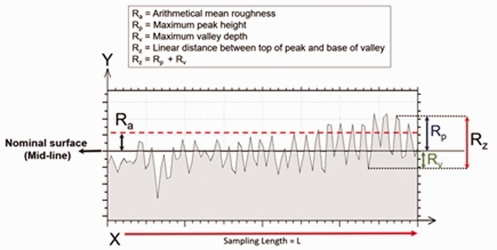
Represnetation of Ra and Rz.
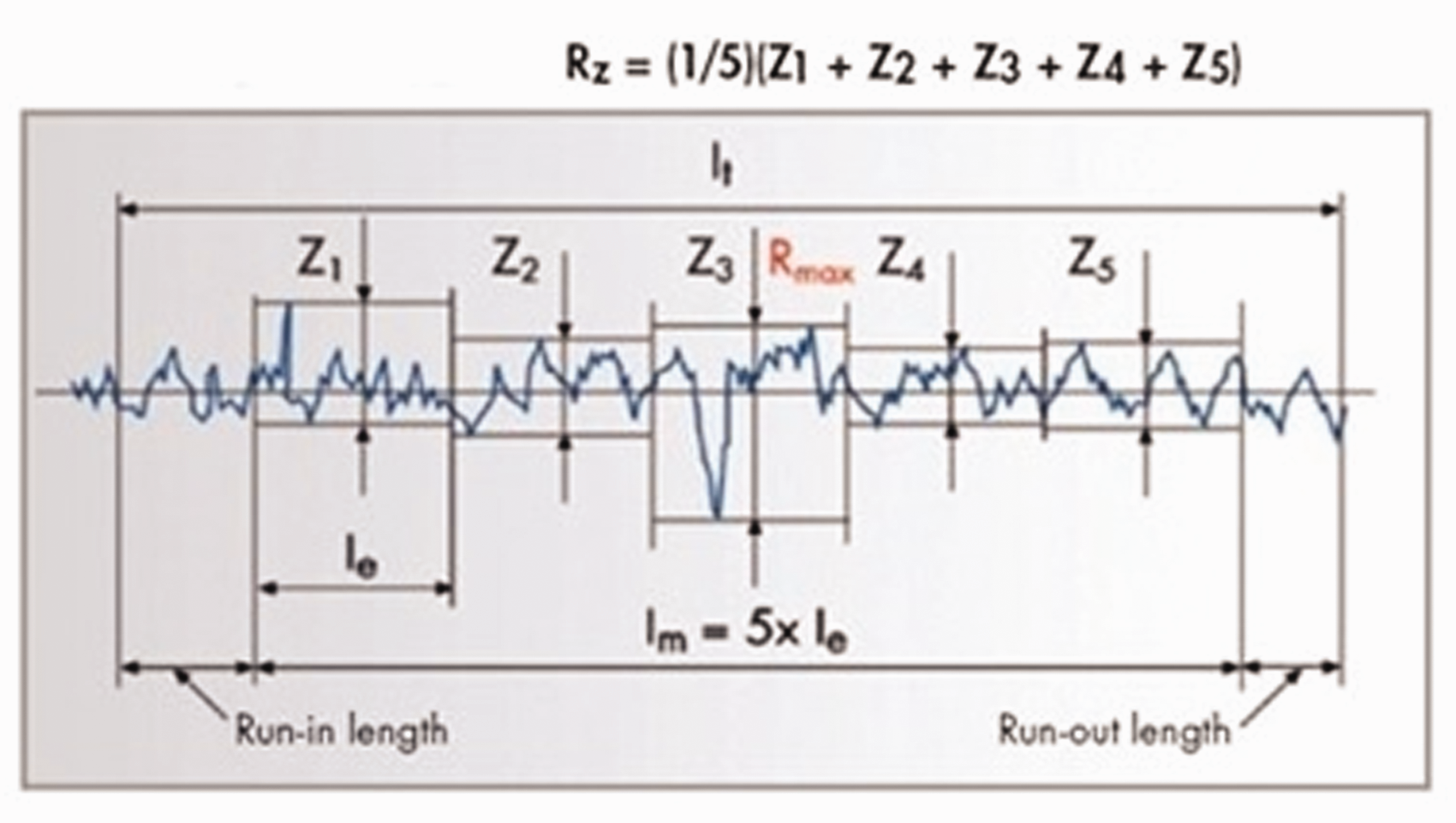
Representation of Rz and Rmax.
Results and discussion
Composite properties
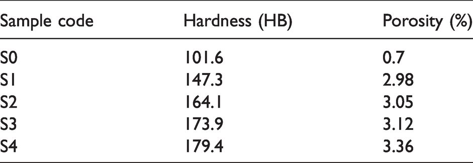
The physical and mechanical test results of samples are presented in Table 4 in terms of porosity and Brinell hardness of the MMCs which were produced by powder metallurgy with 0, 0.5, 1, 1.5 and 2 wt.% of SiC and B4C reinforcements. There has been a significant improvement in the hardness values of the hybrid composites with increase in the weight percentage of reinforcements. It was observed that the hardness value has increased up to 77% with the addition of 2 wt.% of SiC and B4C into the AA2024 matrix. The reason for the high hardness values observed in hybrid MMCs is the uniform distribution of the SiC and B4C reinforcements and the more efficient load transfer from the matrix to the reinforcement in the metal matrix due to the two different reinforcement materials (Figure 4). However, it is also observed that the porosity of the hybrid MMCs increased from 0.7 to 3.36% when the amount of weight fraction of SiC and B4C reinforcement increased in the AA2024 matrix. The addition of more hard ceramic particles into the AA2024 matrix creates the voids because compaction ability of composite powders decreases during the cold or hot pressing.
Porosity and hardness values of AA2024-B4C-SiC hybrid nanocomposites.

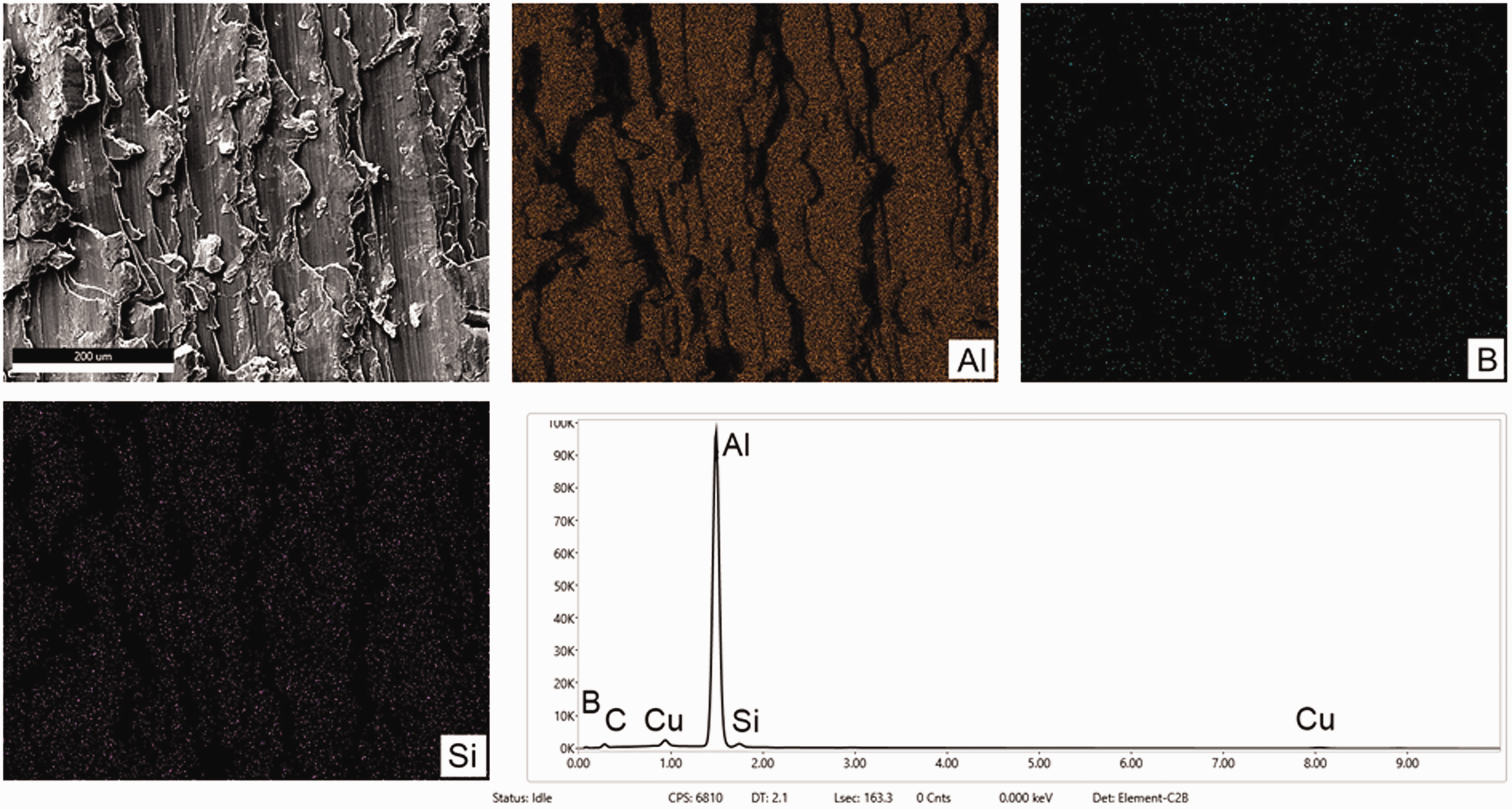
EDX analysis showing the particle distribution of the S2 coded hybrid nanocomposite before machining.
After machining process of the hybrid nanocomposites, the Brinell hardness is also measured and is represented in Table 5. Table 5 also contains comparatively the hardness values for different machining techniques.
Hardness values of AA2024-B4C-SiC hybrid nanocomposites according to machining types.
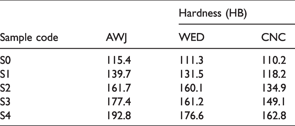
The most obvious result seen in Table 5 is the increase in hardness values for all machining process. The shear deformation of the material is developed during the machining time, even the cutting depth is small. This causes a notable increase in hardness in parent material and a substantially hardened layer is engendered on the machined surface. Hence the hardness is increases on the CNC machined surface. Moreover, the lowest hardness is measured for CNC machined samples. This can be attributed to pull-out of the B4C and SiC particles from the AA2024 matrix during the CNC machining process. The high surface roughness values also confirm this reason. In case of Wire EDM process, electrical sparks are induced for melting and vaporizing the material. During the pulse off time, molten state of materials formed is partially flushed away and the balance is re-solidifies in the molten pool itself. This forms the hard surface on the machined region and increases the hardness of the materials. On the other hand, wire electrode melts during the machining process also removed and partially deposits on the machined region. This also enhances the material properties. The hardness measured on the AWJ machined surface exhibits the highest hardness compared with CNC and Wire EDM machined surfaces. The impact of high pressurized water and garnet mixtures erodes sample and forms a new surface. This impact created on the materials forms shear deformation and it influences the hardness. Also, it should not be forgotten that the machined surfaces in the AWJ are under the effect of rapid cooling due to water jet. The changes in the hardness measured on the surface formed by various machining processes for each composite material is plotted as in Figure 5. It is understood that the hardness of the machined surface is also increases with the reinforcement content.
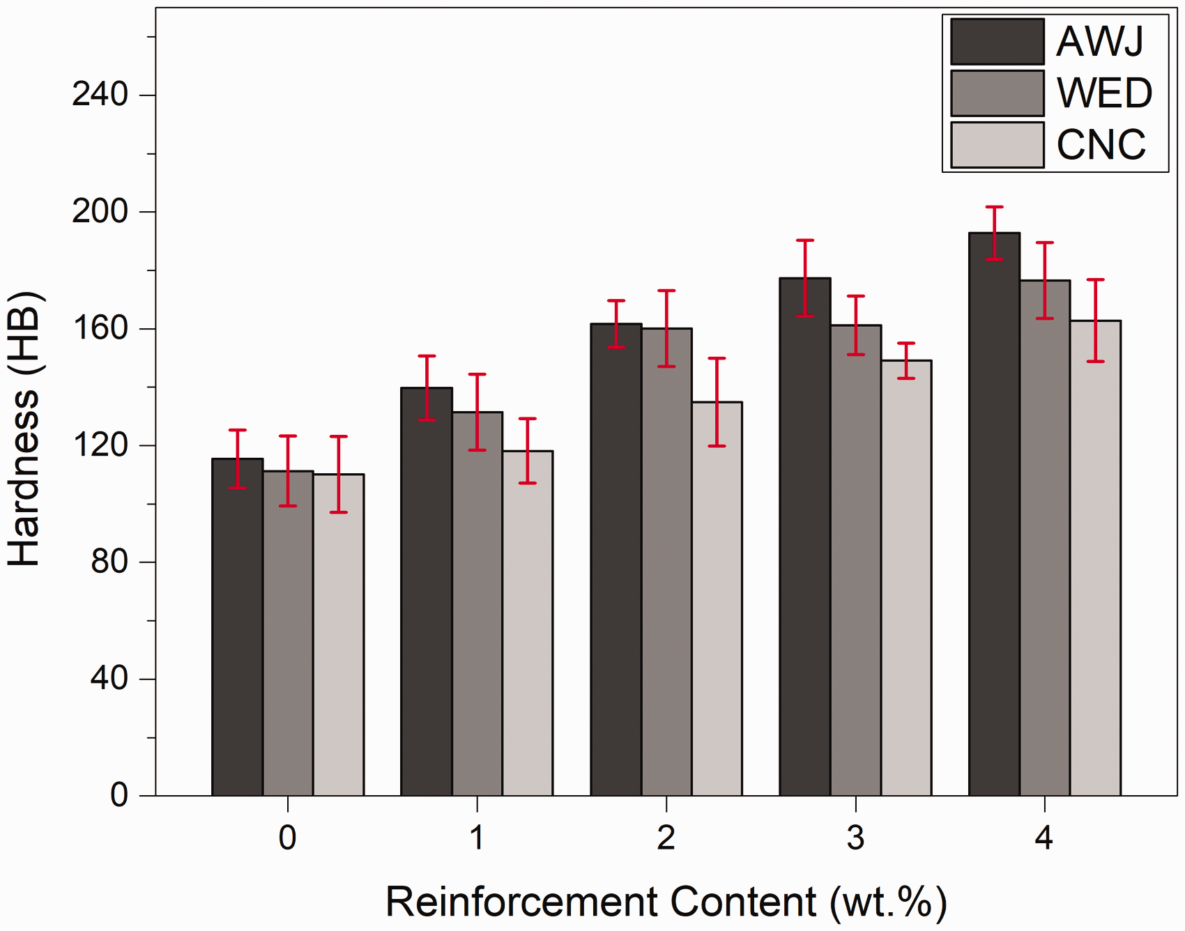
Hardness of AA2024-B4C-SiC hybrid nanocomposites according to various machining.
Influence of machining processes on MRR
The metal removal mechanism of AWJ is a mechanical erosion process and the schematic diagram of AWJ is shown in Figure 6(a). The water jet containing abrasive hits the surface of the material at high speed and erodes the material. The melting and vaporization is the mechanism of material removal in case of Wire EDM process. The schematic representation of WED and CNC machining process are shown in Figure 6(b) and (c), respectively.

Schematic diagrams of machining techniques: (a) AWJ, (b) WED and (c) CNC.
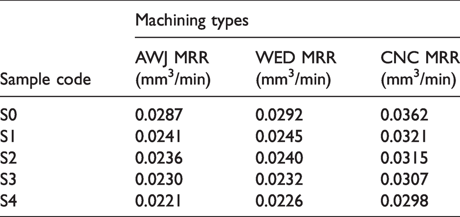
MRR measured for hybrid nanocomposites are presented in Table 6. In general, it is observed that the MRR is decreased with the increased content of reinforcement. The addition of particulates in to the matrix enhances the hardness of hybrid composites and makes it difficult to remove the material. Hence, it slows down the metal removal mechanism and thereby MRR is decreased. The above results are in agreement with the previous studies. Bansal and Upadhyay 34 studied that effect of Al2O3 particle content on the tool wear, surface roughness and metal removal rate of Al-Al2O3 composite. They reported that the MRR of the composites decreases as the reinforcement increases due to hard nature of Al2O3 particles. Rengasamy et al. 35 investigated the effect of the amount of ZrB2 and Tib2 ceramic particles on the machining properties of reinforced Al matrix hybrid composites. They explained that the material removal is maximum for the monolithic Al alloy and it decreases gradually as the amount of reinforcement particles increases. Hybrid composites have a high hardness value that minimizes material loss. This mainly happens due to the presence of Zrb2 and Tib2 particles within the Al matrix. Kumar et al. 36 studied the mechanical properties and MRR in machining process of Si3N4, AlN and ZrB2 reinforced Al matrix composites. They stated that mechanical properties improved with the addition hard ceramic particles and so MRR decreased. The general result observed during the processing of composites is that lower MRR values are obtained compared to pure materials without reinforcement. The first reason for this is the resistance of hard ceramic reinforcement materials to the cutting tool during chip removal. The second reason is the energy loss caused by the collision of the abrasive particles in the cutting tool and the reinforcement powders in the composite structure, and thus the reduction in the cutting force.32,34,35 As a whole, CNC machining process removes the materials in more quantity with the stipulated time period. The metal removal in the turning process is in the form of chips and material deformation in continuous way is noted. Whereas, material removal in the WED machining process are in the particle form, and it is mixed with dielectric medium after removed from the composites. By melting and vaporizing, the material is removed in WED process and hence it takes more time for the metal removal. In AWJ machining process, the material is removed by the jet impact of abrasive and water mixer on the materials and mechanical abrasion leading to the erosion of materials. The kinetic energy of the mixer is utilized for the material removal in AWJ process. In comparison with the other two machining process, the slower material removal is observed here as erosion takes much time to remove the material. The similar trend is noticed for all the composite materials. Figure 7 shows the trend variation of MRR with respect to increased content of reinforcements for various machining processes.
MRR values of AA2024-B4C-SiC hybrid nanocomposites.
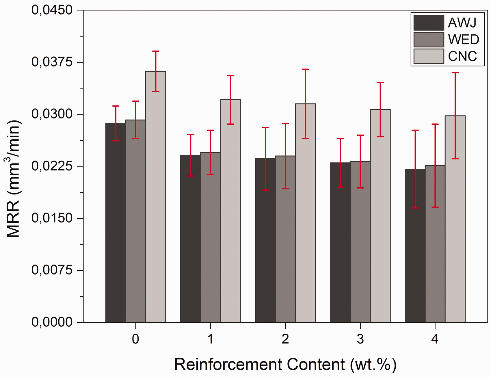
MRR of AA2024-B4C-SiC hybrid nanocomposites.
Influence of machining processes on surface roughness
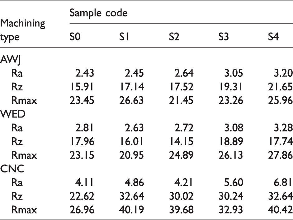
The surface texture of hybrid nanocomposites after machining is represented by the parameters, namely Ra, Rz and Rmax. Table 7 presents the surface roughness values of AA2024 based hybrid composites machined by various machining processes. In general, faster metal removal during the machining process is resulting with the poor surface quality. The addition of particulates into the matrix increased the strength of the materials and slows down the material removal rate. Also, it influences the surface quality and resulting in the increased surface roughness. These results are in agreement with the previous studies. Shoba et al. 37 studied the effect of reinforcement content on the surface roughness of Al matrix hybrid composites. They explained that the surface roughness increases with increasing reinforcement content within the Al matrix. The presence of hard ceramic particulates in a ductile Al matrix can lead to voids around the particle/matrix interface. Ceramic particles are partially or totally removed from the surface and leaving behind cavities of various shapes and depths during the machining process. Some of these particles are passed underneath the tool and dragged by the tool flank along the surface that leads to grooves of various widths and lengths. Therefore, higher roughness values are obtained for higher reinforcements. Anandakrishnan and Mahamani 38 reported that higher TiB2 reinforcement ratio produces higher tool wear, surface roughness and minimizes the cutting forces. Ramesh et al. 39 stated that the increase in the amount of reinforcement particles increases the surface roughness. Among all the machining processes, AWJ machining producing a better surface finish as the lower MRR is observed in comparison with other two processes. Also, the metal removal is in the form of particles is observed in the case of AWJ and WED processes. This results in the formation of comparatively smoother surface than CNC process. WED machining forms comparatively normal wavy surface and CNC turned surface having the rough nature of the machined region. This is because of fast metal removal and also the impact of chips on the machined surface resulting with very rough nature.
Surface roughness (µm) of AA2024-B4C-SiC hybrid nanocomposites.
A significant increase in surface roughness is noted in the CNC turned surface with addition of particles in comparison with other two processes. Figure 8 shows the change of surface roughness with the addition of particles into the matrix for different machined surface.
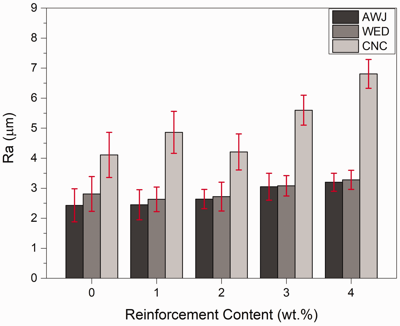
Surface roughness (Ra) of AA2024-B4C-SiC hybrid nanocomposites.
Machined surface characterization
There are important problems in the machining of metal matrix composites such as cracking, fracture, thermal distortion, greater surface roughness, high residual stresses and faster cutting tool wear. On the other hand, these problems can be minimized by advanced manufacturing methods such as AWJ and WED, which are unconventional machining methods. However, optimizing machining parameters and defining chip removal mechanisms while using these methods are issues to be resolved. Abrasive water jet (AWJ) is a method that can process a wide variety of materials such as metals, alloys and composites without any thermal damage and residual stress. The machined surfaces formed by various processes of each hybrid nanocomposites are examined through the SEM analysis. Figure 9 shows the machined surface of AWJ process for various composites. When Figure 9(a) to (e) is examined, it is understood that the micro erosion mechanism is caused by plastic and plowing deformation. For this reason, there are ploughing, cratering and flaking on the machined composite surfaces.23,40 It is understood that higher surface roughness is obtained for the composite having higher content of reinforcements. The worn surface and track of the jet and its directions are evident in the SEM images.

AWJ machining surface (a) S0, (b) S1, (c) S2, (d) S3 and (e) S4.
WED machined surface of hybrid nanocomposites are shown in Figure 10(a) to (e). The higher surface roughness is obtained for the nanocomposite having more reinforcement’s contents. During the machining process, the materials gets melted and partially vaporized. The molten state of materials is flushed away by the dielectric medium during pulse off time. However, partial amount of molten materials are remain in the molten pool itself. This is called recast layer or white layers which form the rough surface on the machined region. On the other hand, collision of craters formed on the machined region during cycle time forms the wave or rough texture on the molten pool. The addition of more reinforcement content makes the process unable to melt the reinforcement content completely as the melting point of particulates differs with matrix. The matrix bond with particles are melted and flushed away during the pulse off time. By that time particulates bind with matrix also removed even not the particle smelted completely. This forms the wavy surface on the molten pool and it is resulting with poor surface quality.

WED machining surface (a) S0, (b) S1, (c) S2, (d) S3 and (e) S4.
The schematic picture of two-dimensional cutting process applied to MMCs and the interaction of the tool tip with the reinforcement particles during the cutting process can be seen in Figure 11. The position of the reinforcement particles relative to the cutting tool tip determines the surface properties that will occur during machining. During the reinforcement interaction with the cutting tool, the reinforcement particles could be sheared (Figure 11(b)), pulled out (Figure 11(c)) and embedded into the material inner surface (Figure 11(d)). Hard reinforcement particles slide in front of the cutting tool tip and agglomeration occurs depending on the ductility of the matrix material. This situation causes the cutting tool to wear more than other interactions.40,41
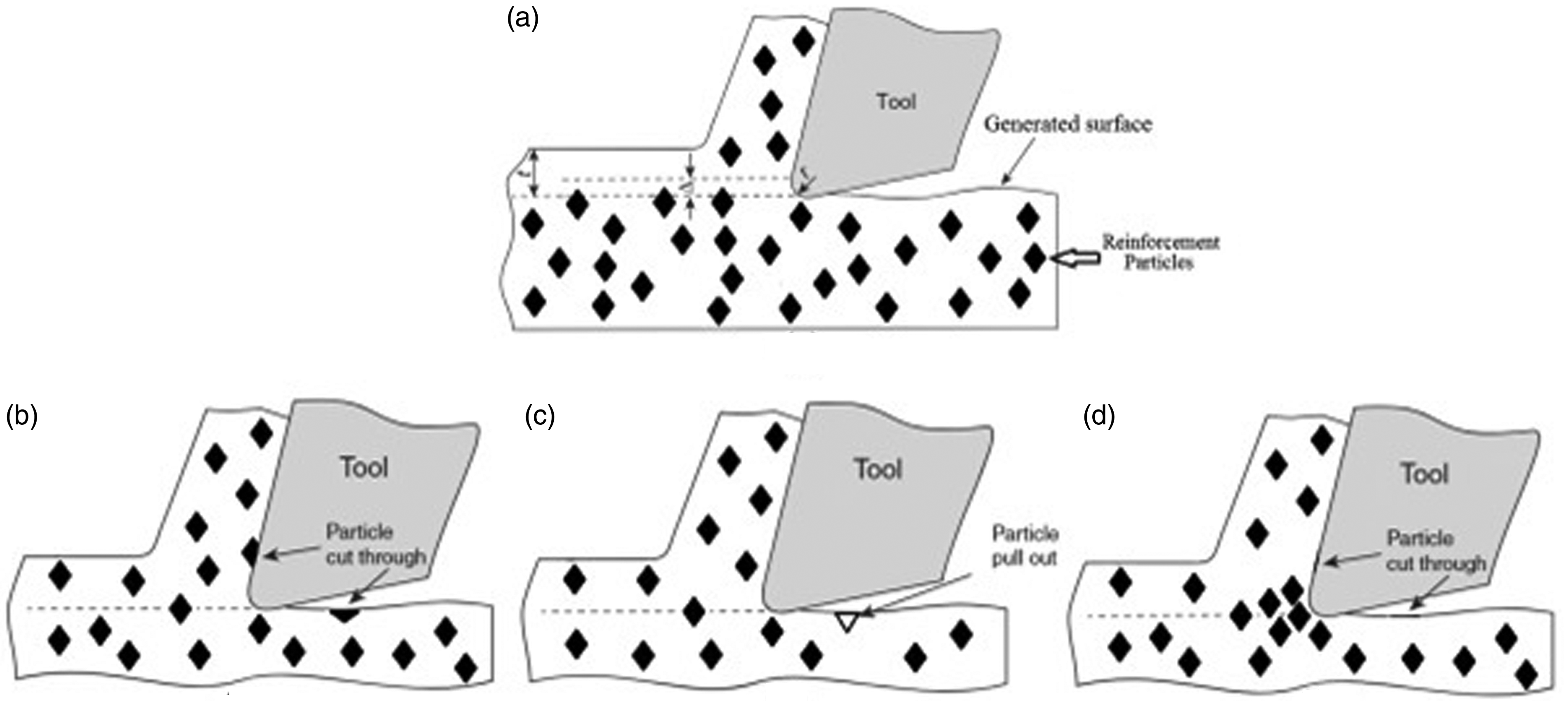
Schematic diagrams: (a) MMC cutting process, (b) particle cut through, (c) particle pull out and (d) embedded particles. 41
CNC turned surface creates very rough nature and rigid layers on the machined surface and resulting with higher roughness compared to other two machining processes (Figure 12(a) to (e)). The machined composite having maximum reinforcement content is having higher roughness than other composites. When high hardness ceramics such as B4C and SiC are added to the matrix structure, the final surface obtained as a result of machining naturally changes due to the pits, voids and groves on the machining surfaces. When the amount of reinforcement added to the matrix structure is increased, the amount of pits, voids and groves on the machined surfaces increases even more. This increase is due to the increasing stress concentration and the inhomogeneous plastic deformation due to the increasing reinforcement content. Also, with the increase in the reinforcement ratio, the cutting tool or cutting material wears out faster and therefore a worse finish surface is obtained.42,43

CNC machining surface: (a) S0, (b) S1, (c) S2, (d) S3 and (e) S4.
EDX mapping of sample S4 on the AWJ, WED and CNC machined surface is presented in Figures 13 to 15, respectively. Figure 13 shows major alloying elements of AA2024 alloy and reinforcement particles are evident from the analysis. During the WED machining process, the eroded electrode sometimes deposited on the work piece materials. This can be attributed to the efficient flushing on the localized region during the pulse off time. Hence, the electrode is deposited and re-solidified of the machined region itself. The presence of wire electrode materials on the machined surface is also evident from the EDX mapping (Figure 14). The alloying elements of matrix materials and particulates are presented on the machined surface which is shown in Figure 15.
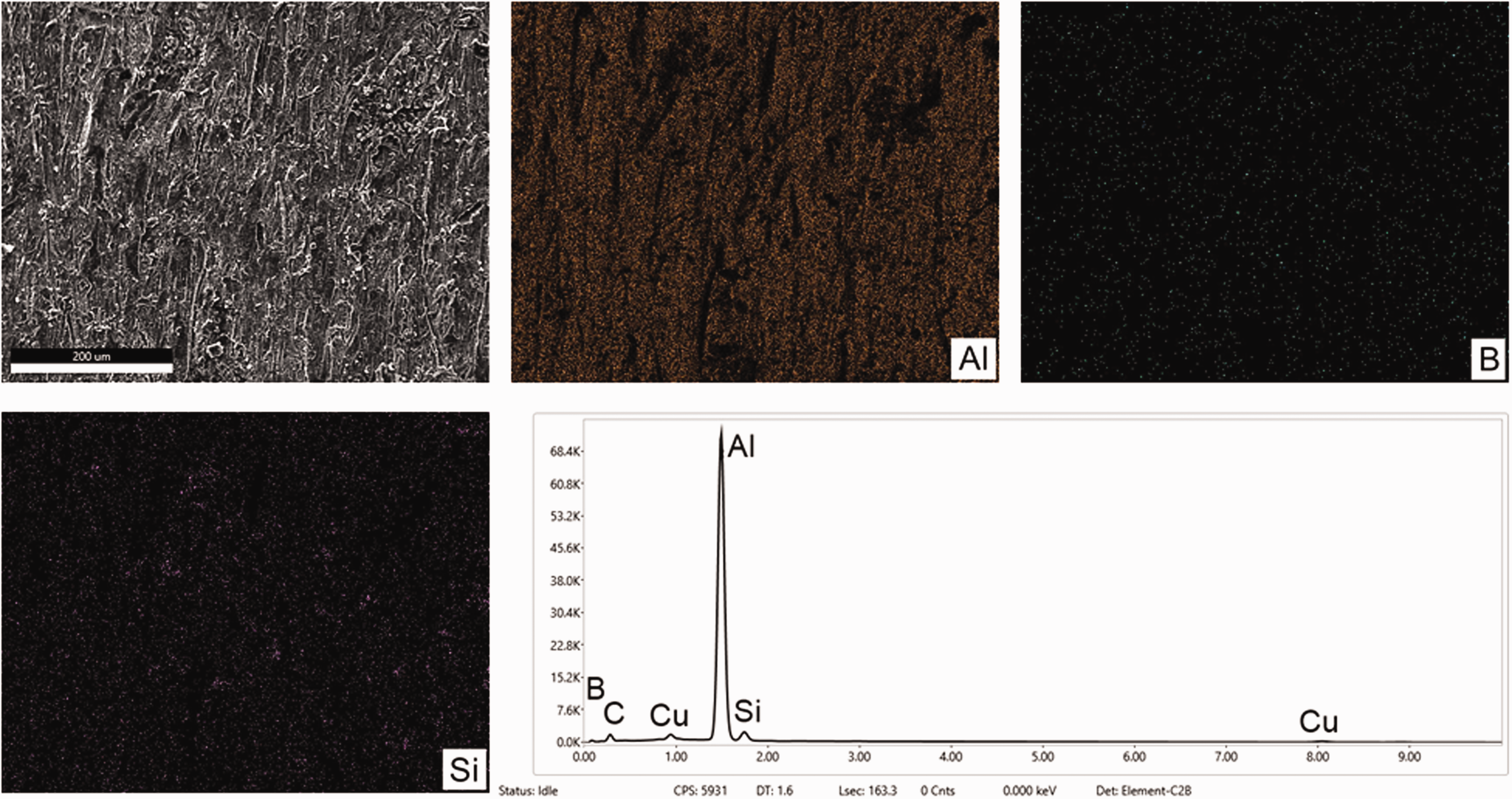
AWJ machining EDX analysis of S4 sample.
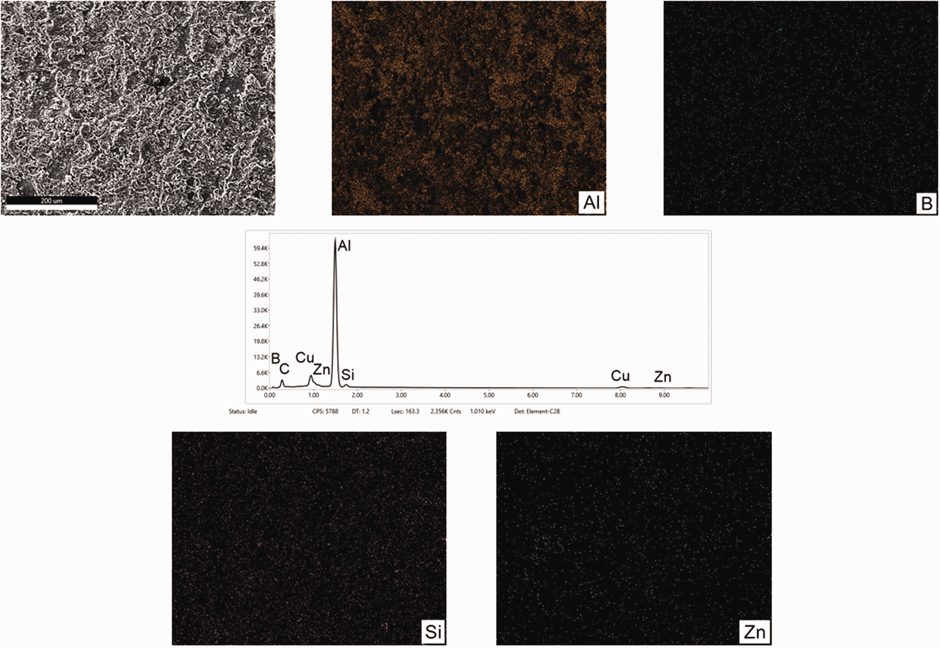
WED machining EDX analysis of S4 sample.
CNC machining EDX analysis of S4 sample.
Conclusions
In this work, AA2024-B4C-SiC hybrid nanocomposites fabricated by hot pressing method were successfully fabricated by the powder metallurgy technique. The samples were subjected to AWJ, WED and CNC machining techniques to determine the effect of reinforcement content on the surface morphology, hardness, MRR and surface roughness. Some important points from the comparative results are drawn below:
The hardness of the various machined surface is also observed. It is understood that AWJ machined surface is comparatively harder than other machined surface. The hardness of S0, S1, S2, S3 and S4 samples machined by AWJ technique are 115.4 BHN, 139.7 BHN, 161.7 BHN, 177.4 BHN and 192.8 BHN, respectively. Minimum hardness value (110.2 BHN) is measured in S0 samples machined by CNC technique. Also, the hardness of the machined surface is increased with the inclusion of particulates. MRR results showed that hybrid composites machined by AWJ technique has minimum MRR of 0.0221 mm3/min whereas monolithic AA2024 alloy machined by CNC method has maximum MRR with value 0.0362 mm3/min. The surface roughness on the machined surface was measured for each machining process and CNC machined surfaces has higher roughness. Surface roughness (Ra) of AA2024 alloy is 4.11 µm and this increment to a maximum of 6.81 µm for the S4 samples machined by CNC. The samples machined by AWJ showed a minimum surface roughness (Ra) of 2.43, 2.45, 2.64, 3.05 and 3.20 µm for S0, S1, S2, S3 and S4 samples, respectively. Moreover, surface roughness values increased with the addition of nano particles within the AA2024 alloy matrix. SEM and EDAX images show that SiC and B4C particles can be distinguished from the AA2024 matrix with a different color scale. As a result of machining, the matrix composite structure maintains its integrity, while the reinforcement particles are broken into small pieces and the surface quality improves. This improvement is due to the reinforcement particles filling the pores in the matrix structure during machining. In addition, the place of the particles separated from the matrix is filled by the deformed matrix, thus preventing the increase in surface roughness. The energy-dispersive spectroscopy results indicate that the chemical composition on the material surface after machining process is nearly the same as the hybrid nanocomposite material composition. However, the amount of copper on the machined surface of WED is more evident than other machining methods. This can be attributed to the deposition of electrode wire material on the machined surface during the WED process.
Footnotes
Declaration of Conflicting Interests
The author(s) declared no potential conflicts of interest with respect to the research, authorship, and/or publication of this article.
Funding
The author(s) received no financial support for the research, authorship, and/or publication of this article.