
Abstract
Resin injection pultrusion gains increasing attention as it enables the use of highly reactive resins and resins sensitive to environmental conditions, while also decreasing the emission of harmful volatile organic compounds. Nevertheless, a comprehensive understanding of the flow field based on the geometric characteristics within open injection boxes is lacking due to a multitude of interdependent parameters. In this research, a novel setup for an experimental evaluation of the flow field in injection pultrusion practically is proposed. The setup consists of a full size, two-dimensionally tapered, transparent injection box that is installed within a pultrusion line and is operated with non-reactive fluids. Investigations are conducted with two different guide plate setups. Pulling forces and filling degree are evaluated for four pulling speeds, four fiber volume fractions and for four fluids. The non-reactive fluids are three grades of sucrose solution and Mesamoll with viscosities ranging from 13 to 246 mPa.s.
Obtained pulling forces correlate linearly with the product of viscosity and pulling speed. Better fiber wettability properties and additional fiber guiding plates result in lower pulling forces. Backflow fill length displays an asymptotic correlation to pulling forces, indicating different governing mechanisms for these two phenomena. Backflow fill length corresponds directly with resin residence time, which ranges from about 10 to 3 min. The results indicate the possibility of manipulating pressure build-up and resin residence time separately, which would enable tailoring injection box cavity geometries systematically to a specific profile.
Introduction
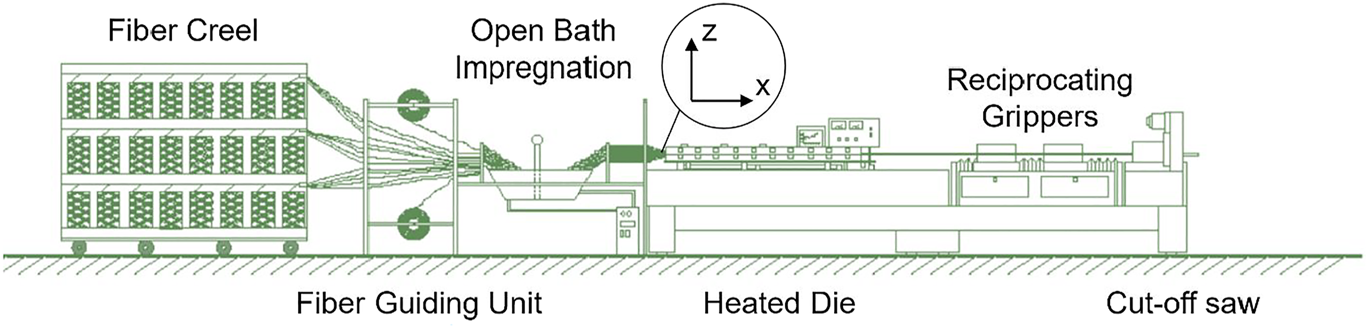
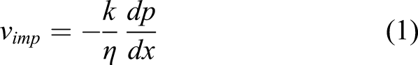
In pultrusion, fibers are pulled through the whole process setup by reciprocating grippers at the end of the machine. The fiber strands, rovings or textiles, are pulled consecutively from the fiber rack, through a guiding system, an impregnation unit and a heated die, which provides the activation energy for the curing reaction as well as the profile shape. A whole machine setup is displayed exemplarily in Figure 1. Illustration of relevant fiber configurations and distinct regions within a two-dimensionally tapered injection box.
1
Open bath impregnation has been the standard impregnation unit option for large numbers of fiber strands that are required to produce a pultruded profile. Due to the long residence time of the resin in an open bath, the reactivity of the material is restricted limiting the pultrusion speed. 1 Additionally, the resin’s large surface area as well as its constant turnover by moving fiber strands contribute to emission of potentially harmful volatile organic compounds (VOC), such as styrene, which recently have become subject to stricter legislation for occupational safety in the European Union.1–3 Furthermore, materials that are sensitive to ambient influences, for example, humidity, or are highly reactive, such as in-situ polymerizing caprolactam or polyurethanes, can hardly be processed in open baths.4–6
Addressing both shortcomings of limited production speeds and VOC emission, injection boxes have been proposed and successfully applied in industry.1,7 General understanding of the flow field within injection boxes is limited due to the wide variety of dimensions that need to be considered and equivocal understanding of general designs. Impregnation happens on the microscale and the backflow volume of the injection box can exceed liters.
The main requirement for an impregnation unit is to achieve full and void-free impregnation, which constitutes a necessary precondition for successfully producing high quality pultrusion profiles. Additional requirements include limited resin residence time to avoid premature curing as well as a sufficient level of process stability to compensate practically random influences, such as roving interaction due to roving twist or external factors, such as purging or roving replacement. Furthermore, minimizing internal pressure is desirable as it reduces mechanical design effort as well as investment costs, especially regarding dosing equipment. 8 It needs to be considered, that higher pressure levels in the injection box reduce the void content. 8
Impregnation can be evaluated on different scales, macroscopic impregnation describes the coating of individual fiber tows and microscopic impregnation addresses wetting of each filament within a fiber tow.
9
The established method for describing fiber impregnation in composite manufacturing constitutes the Darcy equation, which is noted in equation (1)
10
For composite manufacturing, the Darcy equation, originating from the description of flow through sand, connects the impregnation speed vimp through the textile with the porosity, or inverse permeability, k, the viscosity η and the pressure gradient in direction of flow dp/dx. The pressure difference can be interpreted as the difference between the pressure within a fiber tow surrounding fluid and the capillary pressure between single dry filaments, which acts as a suction force. 11 Capillary pressure depends on the specific material parameters surface tension and contact angle as well as capillary radius, which can be correlated with filament diameter.
Based on these governing mechanisms, the main parameter for controlling impregnation in injection boxes is pressure build-up within the fluid, as it can be influenced by process and equipment design.
Investigations on the flow field in injection boxes
Due to the importance of pressure build-up in injection boxes, a multitude of approaches to measure, model, analyze, and control pressure levels have been reported. In general, two main design principles can be distinguished by the cross-section size at injection box entrance. Fibers enter the injection box either at final cross-section and so effectively preventing flow against pulling direction, or the cavity converges continuously towards the final profile cross-section.5,6,8,12,13
The first principle, closed-injection pultrusion, focuses on pressure build-up outside of a compacted fiber strand, which is fed to the impregnation cavity. Pressure is applied as a combination of injection pressure and dynamic pressure build-up between a converging cavity wall and the moving fiber strand.2,14,15 In this case, impregnation can be manipulated by increasing external pressure. Because different factors, such as dosing equipment and sealings, restrict applicable pressures and increasing external pressure compacts the fiber strand resulting in a decreased permeability, pulling speeds are limited for this approach. 15 Furthermore, stagnation areas resulting in clogging of the cavity have been a reported issue. 8
The second principle, open injection pultrusion, uses a continuously tapered geometry with rovings converging towards the die entrance. This approach enables an additional effect of dynamic pressure build-up originating between converging, moving rovings. Main design options for this approach include positioning of the injection point, dosing control, cavity geometry, roving spreading, and roving positioning.16,17 Based on the multitude of options to design open injection boxes no general understanding of inter-tow and impregnation flows is available.
Due to the nature of pultrusion in general and injection pultrusion in particular, the main aspects, impregnation and curing, happen continuously and simultaneously within the injection box and die, impeding a direct assessment and thereby independent investigation of effects of underlying interdependencies. These interdependencies and high experimental effort restrict experimental data, resulting in highly specific datasets with small parameter variations and varying degrees of information on materials and setups.
In order to compensate scarcity of experimental data and its inherent inconclusive interpretations of real pultrusion trials, two main approaches have been established for pultrusion investigations in addition to full-scale pultrusion trials: - Analytical and numerical models, ranging from rather simple analytical 1D-models for the calculation of temperature distributions within the die, considering exothermal heat generation, to complex 3D-Computational Fluid Dynamics and Multiphysics simulations for modeling the whole process, including impregnation as well as cure- and temperature-dependent viscosity development8,17–28 - Simplified experimental representations, where specific aspects of the pultrusion process are evaluated empirically in distinctively developed experimental setups of reduced complexity29–32
Analytical and numerical models rely on constitutive equations, that have been derived from general correlations to investigate occurring mechanisms within the inaccessible process. Safonov et al. offer a comprehensive overview on the available models that are used for all aspects of modeling and simulating pultrusion processes, as well as the main insights gained from these investigations. 10 Pulling force, which needs to be overcome to keep the process running, and impregnation in correlation with pressure build-up represent two main aspects of interest. It needs to be considered, that pressure build-up in the injection box also contributes to the Pulling force.
Different models for pulling force development, developed, for example, by Blaurock and Li et al., agree on considering compression forces, viscous forces, and friction forces.30,31,33 But calculation, considered parameters and assessment of significance vary significantly. Most authors agree on a rather small contribution to the pulling force, originating in the injection box, as superposed friction forces within the die dominate.31,34
Modeling pressure build-up in tapered injection boxes requires a description, that combines the converging cross-section and the development of fiber positioning within the injection box. The majority of published work relies on applying the Darcy equation, see equation (1), and modeling porosity as a function of local fiber volume fraction assuming a homogeneous porous domain. These models for fiber impregnation origin from the application of models for anisotropic permeability. Generally, the permeability in fiber direction is modelled by the Kozeny–Carman equation; however, for the permeability transversal to the fibers, models by Gutowski et al. and Gebart are commonly used.35,36 Unfortunately, these permeability models are hard to validate or calibrate experimentally for the specifics of the pultrusion process. Due to that, permeabilities are often measured directly,8,37 whereas it needs to be considered, that permeability measurements are method dependent. 38 Additionally, simulation model accuracy is limited by element size or calculation power, resulting in averaged material properties, which are not able to consider all relevant scales in the same model. This might be a reason, why in the vast majority of publications the cavity is tapered only in vertical direction.
Masuram et al. include an additional phenomenon into their models by also considering the fiber compaction behavior. The considered fiber compaction origins from the injection pressure at the injection points and leads to fiber compaction towards the middle of the profile resulting in a decreased porosity. Their simulation studies yield, that higher fiber volume fractions require higher pressure for fiber wet-out and that larger tapering angles decrease required injection pressures. 39 Additionally, they investigated the influence of pulling speed and resin viscosity on wet-out and found, that increasing each quantity makes wet-out harder to achieve.40,41
Different publications evaluate the model validity by comparing the simulated pressure build-up within the cavity to pressure levels that are measured at the cavity walls in real pultrusion processes. Bezerra, varying fiber volume fraction, and Ding et al., varying pulling speed, measure higher pressures within the cavity than expected by the respective models.8,42 Bezerra also reports good correlation of an adapted analytical model from Li et al. with his simulations. Brennan et al. also compare their model to two pressure levels within the cavity, which displays an overestimation far from the die entrance and an underestimation close to the die. 17 Tucci et al. include air as an additional phase to be considered in modeling the flow in the injection box. Within their investigations they compared pressure levels in the cavity, with a good agreement for a pulling speed of 0.3 m/min and an increasing deviation for 0.5 m/min. 20
Deviations between model and measured values are mostly attributed to the lack of considering roving twist and fiber-fiber interactions. As the investigated data points are rather scarce, focus on low pultrusion speeds, and diverge when scaling with speeds, the representation of geometric influences in the models is questionable. Especially, when considering productivity optimizations, which aim for higher production speeds of 3 m/min, 43 or applying the models to more complexly shaped profile cross-sections and injection box cavities a high accuracy of the representation of geometric features is necessary.
An efficient way of investigating fluid flow in composite manufacturing practically is the application of transparent dies in combination with non-reactive testing fluids, such as glycerin.30,44,45 For example, Hogade et al. evaluate their analytical model for predicting the linear dependence of pulling force on the pulling speed in a transparent die with constant cross-section, which enables additional qualitative evaluations of the resulting flow field. They report an interesting observation of local flow field instabilities, resulting in the fiber mat to be pushed to one wall of the die and so significantly changing the boundary conditions for the flow. 29 A similar effect, leading to incomplete impregnation was observed by Hopmann et al., with rovings in an injection box for high viscosities and small compression due to small cavity opening angles. 46
Considering the presented limitations and uncertainties within the assessment of the flow field, especially concerning geometric features, in injection boxes, the scope of this research article is to introduce and evaluate a novel experimental investigation method based on a transparent injection box operated with representative non-reactive fluids. Without the limitations of curing resin, a wide range of pulling speeds and fiber volume fractions for different viscosities are investigated to address data scarcity prevalent in injection box evaluation. The geometry of the investigated tapered injection box features a comparatively large two-dimensional opening to amplify the effect of local fiber volume gradients. This experimental procedure enables the measurement of resulting pulling forces and backflow fill length, which is introduced in Theoretical Evaluation of the Flow Field in Injection Boxes. These resulting quantities are evaluated regarding the implications of the investigated process parameters on the pressure build-up, in order to explore the opportunities of an alternative injection box design approach for injection pultrusion. Additionally, the influence of an improved fiber guidance setup with additional guiding plates is investigated to assess the influence of an external factor on the flow field.
Theoretical evaluation of the flow field in injection boxes
The relevant flow field can be summarized by the term backflow area as it is determined by the fluid, that fills the cavity against the pulling direction due to the dynamic pressure build-up. When considering single fiber rovings and resulting inter-tow flow in an injection box cavity tapered in two directions, three different regions can theoretically be distinguished. For an initial approach, the fiber tow position is assumed to be determined by the guiding plate and a fixed position in the final profile geometry. Figure 2 illustrates these three regions, which are generally distinguished by distance between single rovings, whereas no distinct threshold values are available. Additionally, Figure 2 defines the parameter backflow fill length LDist, which helps to quantify the volume of resin that stationary fills the cavity. The illustration in Figure 2 prerequisites an volumetrically controlled injection before the filled volume, which requires the incoming fibers to drag the resin into the filled volume. Alternatively, pressure-controlled injection into the filled area results in additional pressure build-up and an even more complex flow field.
8
Illustration of relevant fiber configurations and distinct regions within a two-dimensionally tapered injection box.
Region I, closest to the final cross-section (B:B and C:C) opposite to the pulling direction, can be identified by small areas of resin in between fiber tows (B:B). The high filament density close to the die entrance (C:C) makes it impossible to identify individual tows. Characteristically for this region is, that the total area of resin between the fiber tows are at least in the same order of magnitude as the fiber tow’s area or smaller, which results in small gap heights between rovings. Due to the fact, that the cross-section area of a dry roving as well as cross-section shape can only be approximated and rovings are twisted, a distinct formal description is impeded.
In contrast to that, Region II, can be interpreted as a one-dimensional flow in a converging slit with moving walls, which is formed by overlapping rovings coming in (A:A). This assumption requires the guidance plate to enable the planar formation of the rovings, for example, by guiding the incoming rovings through horizontally aligned holes. Additionally, it must be acknowledged, that a closed plane is always an approximation as gaps can occur locally due to roving twist or missing rovings, which can be necessary to decrease the fiber volume fraction.
When also horizontal opening of the injection box is applied or single roving positions are not staffed, another region can be identified. Region III begins when the width of the injection box exceeds the sum of widths of the incoming rovings in one plane and gaps between the rovings must occur. Additionally, a horizontal opening leads to a vertical dispersion of the single rovings, which is illustrated in the side view of Figure 1.
Assessment of impregnation in tapered injection boxes
Koubaa et al. developed a set of coupled differential equations based on a 1D flow model to investigate the impregnation behavior of (tubular) textiles pulled through a (tapered) tube with thermoplastic resins and analyzed derived dimensionless parameters regarding viability of continuous profile production with polymerized thermoplastics. 11
One of the described dimensionless numbers assesses the relation of the textiles’ resin exposure time tp to the required time ti for impregnation of the textile’s thickness.
11
Based on this dimensionless number full impregnation solely by capillary forces can be expected when exposure time exceeds required impregnation time. This behavior corresponds with the illustration in Figure 3. Illustration of relevant dimensions and properties regarding the required backflow fill length.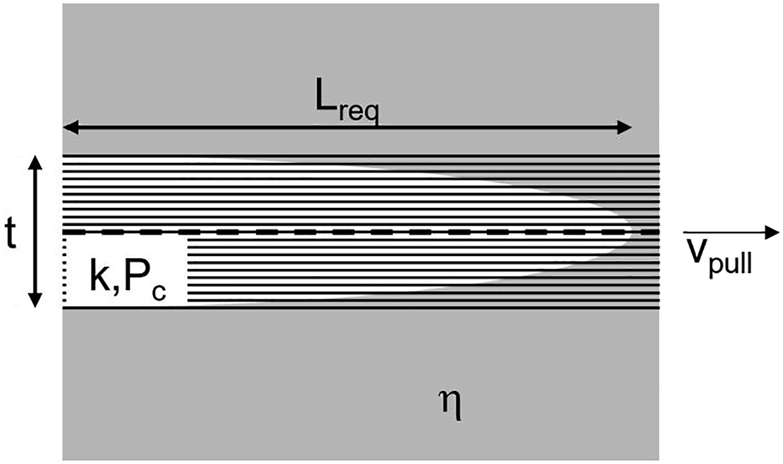
Following relation, equation (2), for required backflow fill length Lreq is derived from the mentioned dimensionless number, when assuming the whole roving is externally covered with resin
11
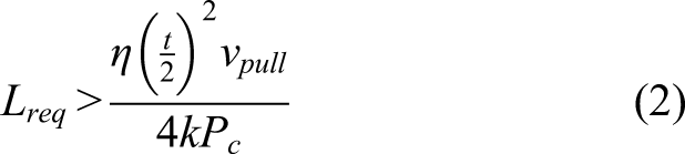
In this equation, viscosity η, roving thickness t, pulling speed vpull, are related to inverse porosity k, and capillary pressure Pc. A comparison of the parameters’ orders of magnitude for the numerator and denominator yields for reasonable pultrusion values (η = 1 Pa.s, vpull =1 m/min, k = 10−13 m2 and Pc = 102 Pa) a required exposure length for impregnation in the range of millimeters when single rovings are impregnated through the thickness (t = 0.4 mm). Additionally, it emphasizes the importance of porosity as it can range through a multitude of scales based on external pressure, whereas higher pressures decrease porosity.8,37 Even though pultrusion resins generally are considered to feature good wettability properties, capillary pressure is a material combination specific property, that needs to be evaluated for validity of specific resin fiber combinations.
According to the presented reasoning, it is reasonable to initially assume, that single rovings are impregnated rather quickly through the thickness mainly based on exposure and capillary forces, when they enter the filled volume of the injection box. This indicates that impregnation and relevant pressure build-up are separated effects in open injection boxes. The impregnation status of the rovings affects the compressibility of the rovings and so directly results in differences in dynamic pressure build-up mechanisms in the injection box.
Dynamic pressure build-up in the injection box
When considering incoming fibers as impregnated, pressure build-up description against the pulling direction in the injection box (denoted by
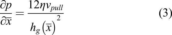
As can be seen in equation (3), viscosity η, and pulling speed vpull, contribute linearly to pressure build-up, which can be summarized as the dynamic contribution to pressure build-up. In contrast to that, the geometric contribution, represented by the squared local gap height hg, remains inaccessible as no formal description of gap height is available, which is visually emphasized by cut-planes B:B and C:C in Figure 1. It can also be inferred from equation (3), that due to the slow speeds in pultrusion significant pressure build-up requires very small gap heights of a millimeter and below.
Furthermore, it needs to be considered, that for large gap heights dynamic pressure build-up is even smaller, as a boundary layer of laminar flow induced by the moving rovings is formed.
Pulling forces in the experimental model setup
Pulling force needs to be continuously overcome in order to keep the fibers moving through injection box and die. Due to easy access, it is one of the major parameters to evaluate process stability in pultrusion (1). As mentioned in Investigations on the Flow Field in Injection Boxes pulling forces are considered to result from a combination of compression, viscous and frictional forces. Applying these models to the experimental model setup, which does not include the effect of curing material, results in an addition of forces generated in the injection box FI-box from pressure build-up, as outlined in equation (4), and viscous forces in the die attachment.
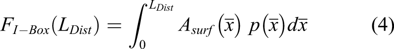
The pulling force generated in the injection box is determined in between the final profile cross-section and the required backflow fill length LDist by the local pressure
The viscous forces in the die attachment are based on a Couette flow between moving filaments and wall. The main relevant parameters are viscosity and distance, which is approximated based on filament diameter and fiber arrangement. 10
Injection box cavity fill length
As outlined in equation (4) the fill length LDist is a variable for determining the total force generated in the injection box. But simultaneously it is also dependent on dynamic pressure development, as there will be gravitational effects taking over governing the flow behavior once hydrostatic pressure phydrostatic exceeds dynamic pressure pdyn, offering additional information on the local pressure level at this point, which can be described as in equation (5)
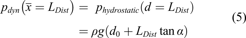
This description includes fluid density ρ and gravitational acceleration g in addition to the geometrical factors mentioned before, see also Figure 5.
Experimental
In this chapter, the setup, materials, experimental procedure and data evaluation are presented.
Development of the test-setup
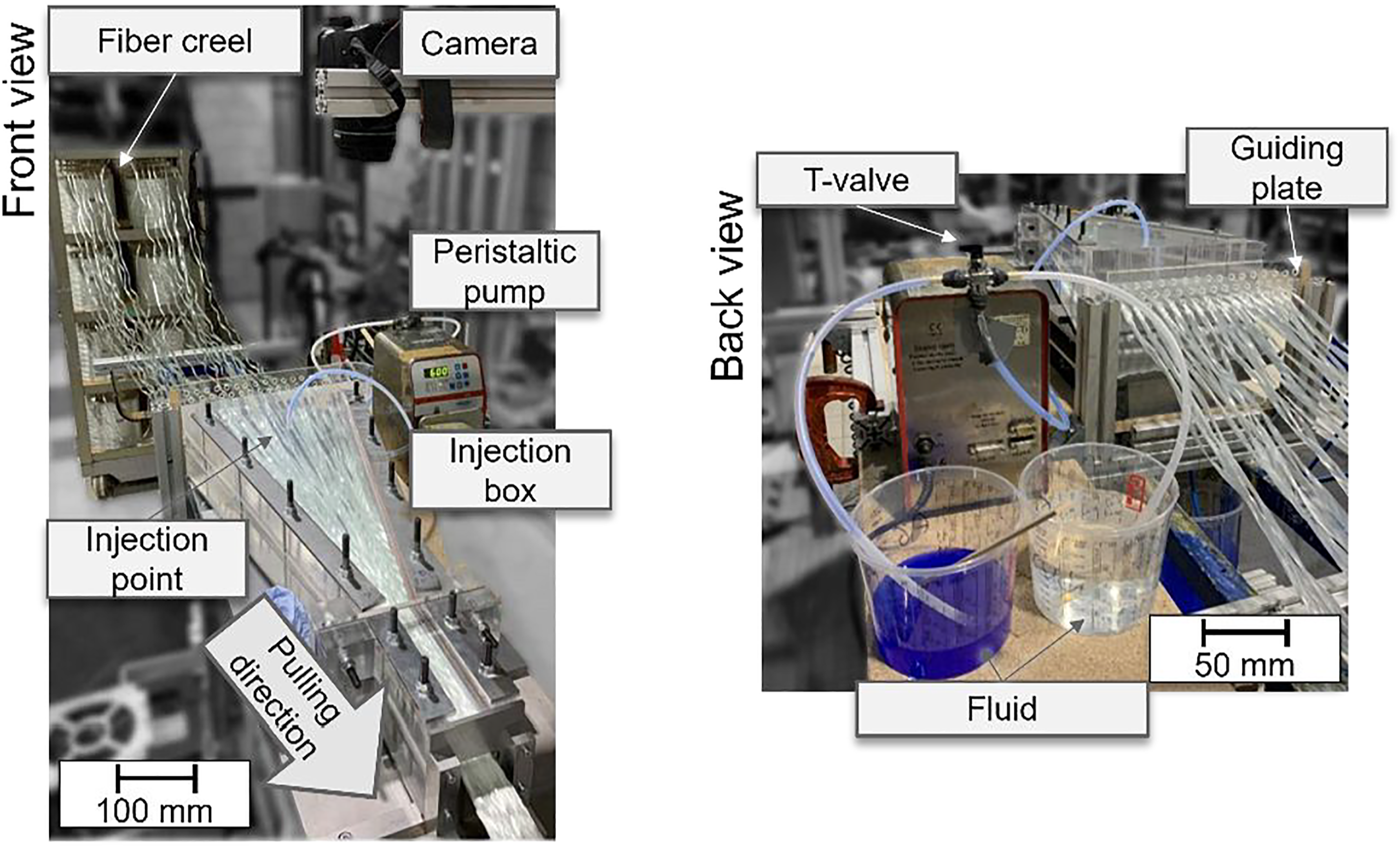
The presented setup for process near flow field investigation is integrated in a Pultrex 500 pultrusion machine by Pultrex Ltd., Lawford, England, with reciprocating pullers, enabling pulling speeds of up to 2.2 m/min. The setup features a sledge setup for mounting the die equipped with an C9C force sensor by Hottinger Baldwin Messtechnik GmbH, Darmstadt, Germany. Force sensors of this type with a maximum force of 500 N and 5000 N were used for the presented experiments. Process parameters such as pulling speed and pulling force are acquired continuously with a rate of 2 Hz.
A modular, transparent injection box with a die attachment was designed and manufactured from Polymethyl methacrylate (PMMA), which is shown in Figure 4. PMMA is chosen for its transparency as well as good wear resistance, which results in no observable wear after all trials for this study. For the injection box, an upper and lower component are used in combination with wedges, which shape the cavity by defining the vertical as well as the horizontal opening. Wall thickness of the plates is designed to limit displacement to 1 mm at a stress of 20 MPa, representing the highest reported value inside an injection box.
1
Due to the fact, that the assumed maximum stress exceeds realistic pressures of about 1 MPa immensely, no significant displacements are expected.
8
In order to ensure sealing of the modular parts, each surface contact is sealed. A metallic plate is used as a connector between the injection box and the die attachment to ensure positioning and sealing. Total view of the modular injection box developed for investigating flow mounted on the sledge.
52
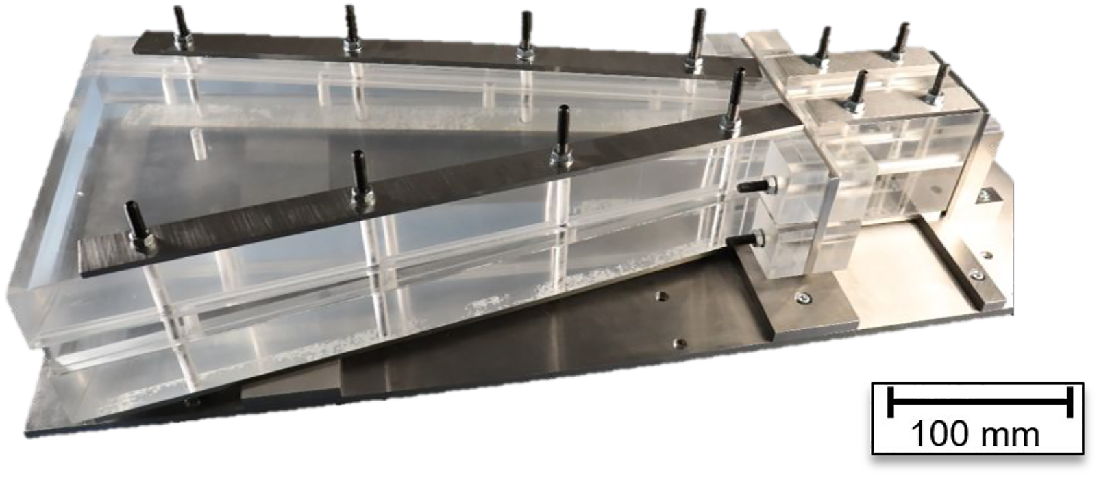
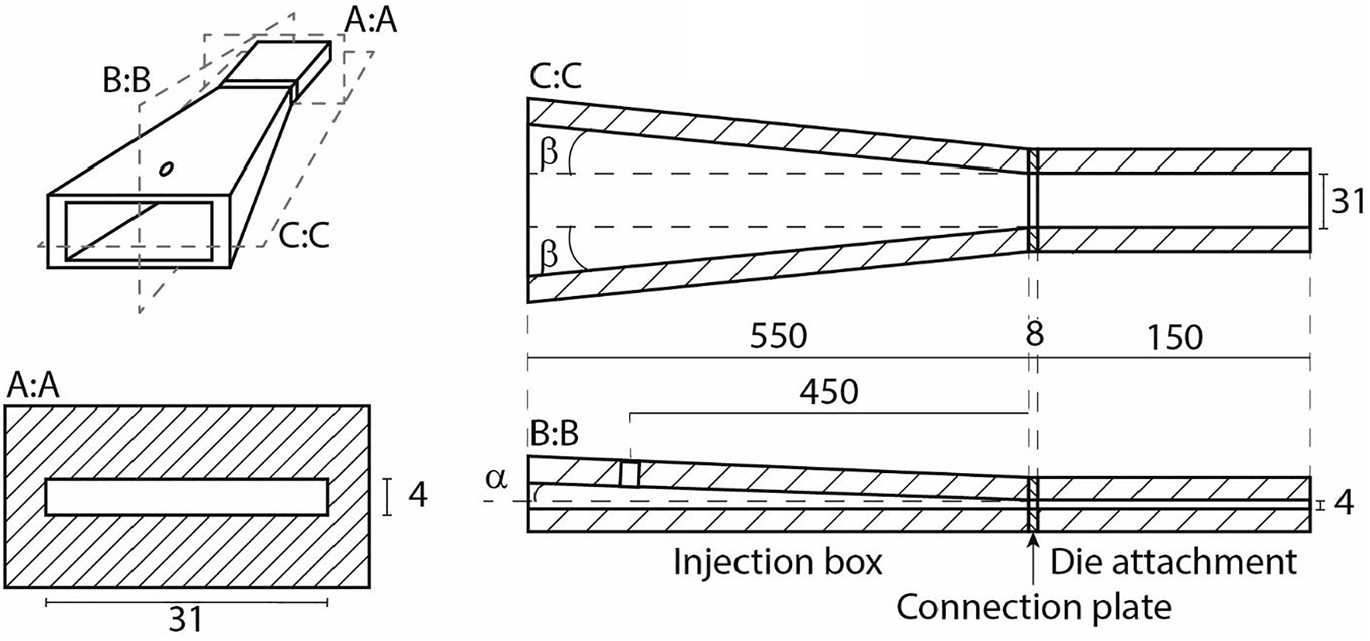
Figure 5 summarizes all dimensions of the developed transparent injection box. The profile cross-section of the die attachment is 31 mm wide (b0) and 4 mm thick (d0). The converging injection box geometry features an upwards vertical opening angle α of 2.5° and horizontal opening angle β of 10.9°, each respective to the main axis. The length of the converging injection box is 550 mm. The die attachment features a length of 150 mm. The injection point with a diameter of 10 mm is located 450 mm upstream from the final profile geometry at the end of the converging injection box, which is behind the backflow flow front for all investigated parameters. General dimensions of the injection box cavity (dimensions in mm).
46
Based on these dimensions the local profile cross-section

Furthermore, the setup includes a fiber guidance plate for 46 rovings, which is mounted in a distance of 100 mm upstream of entering the injection box. The hole pattern and spacing is shown in Figure 6. The guiding plate is oriented for the lowest row to align with the horizontal bottom plate of the injection box. Pattern and spacing of the implemented guiding plate.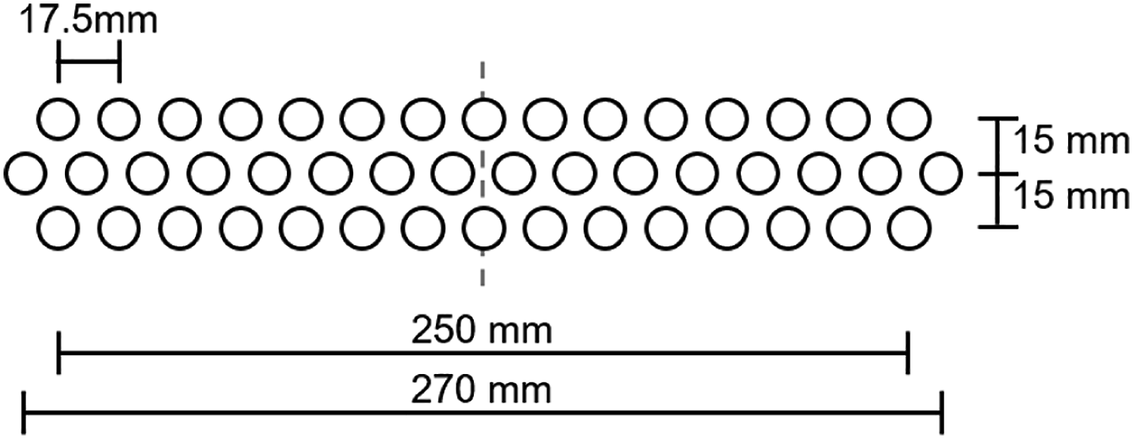
Materials
All experiments are carried out using StarRov 090 4800 tex, glass fiber rovings by Johns Manville Europe GmbH, Wertheim, Germany, which is a common choice for pultrusion applications. This roving is coated with a silane sizing. The rovings are pulled from the roving using center-pull. Based on this, each roving is twisted as it is pulled through the process and no measures to eliminate the fiber twist are taken. This process design results in a distinct time-dependent configuration of each roving entering the injection box, which can be considered for practical reasons random.
Four different fluids with relatively low viscosities are used for the investigations. Fluid selection aims to represent typical processing viscosities of resins for injection pultrusion, which usually feature viscosities on the lower end of the available spectrum. Initial processing viscosities can be as low as 5 mPa.s for ε-Caprolactam and 90–280 mPa.s for polyurethanes.13,47 During processing of the mentioned materials and other materials in general significantly higher processing viscosities are reached due to the curing reaction.
Three different sucrose solutions (abbreviated: SuS/Suc. Sol.) are prepared with varying mixing ratios. The mixing ratios are 1:1, 5:3, 2:1 (mass fraction: sugar to water). Solution preparation includes heating up water and mixing in the respective amount of sugar. After mixing the solutions are cooled down and stored in a sealed container until processed in the experiments. Additionally, Mesamoll, which is the tradename for an alkylsulphonic acid ester with phenol by Lanxess AG, Leverkusen, Germany, is investigated in order to include another material with a comparable viscosity but varying chemical constitution, which impacts the surface tension and accordingly the wetting behavior.
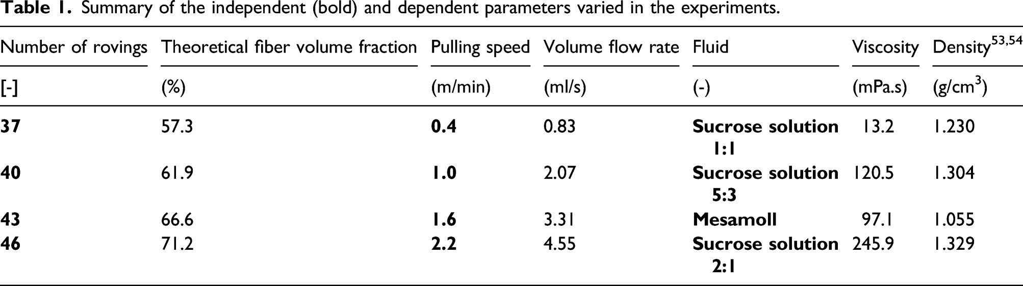
Summary of the independent (bold) and dependent parameters varied in the experiments.
Additionally, wetting behavior of the investigated fluid-fiber combination is characterized qualitatively in order to get an impression of the applicability of the capillary based impregnation, outlined in 3.2. Therefore, an OCA 15EC device for contact angle measurement by Data Physics Instruments GmbH, Filderstadt, Germany, is used and fluid drops are placed on a roving. Sucrose solution initially builds a droplet on the roving surface and dissolves slowly into the roving with time. Mesamoll dissolves directly into the roving. Due to this behavior, it can be assumed, that Mesamoll impregnates the fibers very quickly based on capillary forces without any external pressure. In contrast to that, sucrose solution for all investigated mixing ratios requires significantly more time or external pressure to impregnate the rovings, as would higher viscosity fluids.
Parameter variation
The investigations aim to cover a wide range of relevant parameters. Hence, two of the main independent parameters in pultrusion, namely, pulling speed and fiber volume fraction (FVF) are varied in addition to the mentioned fluids. Based on the maximum available pulling speed of 2.2 m/min equidistant pulling speeds are defined. The chosen number of rovings covers a range of 57.3–71.2% theoretical FVF. For all trials, the same guide plate is used, approximating a balanced roving distribution when selecting rovings to remove for trials with a lower number of rovings. Table 1 summarizes the independent parameters varied in this study as well as dependent parameters that are varied implicitly or explicitly according to the dependent parameters.
The theoretical FVF, which depends directly on the number of rovings and the profile cross-section, is calculated assuming a density of 2.5 g/cm3 for glass fibers. 48 Even though volume flow rate is an independent parameter in pultrusion, for this study fixed values linearly correlated to the pulling speed are chosen to reduce complexity. For dosing, a peristaltic pump of the type Ismatec MCP Process by Cole Palmer GmbH, Wertheim, Germany, is used, providing a constant volume flow rate. The peristaltic pump conveys the fluid through a hose with an inner diameter of 6 mm, that is plugged into the bore at the injection point.
The flow rates are determined by the profile cross-section times the pulling speed, leading to an overfill of the cavity, which is not considered to affect the equilibrium state significantly as the excess fluid flows to the cavity opening against pulling direction. 29 This approach is chosen as it avoids several issues, that can occur with such injection box configurations. On the one hand, overfilling ensures, that at all times a sufficient amount of resin is supplied as single rovings are separated at the point of injection and it cannot be guaranteed, that all fluid injected is dragged into the process. On the other hand, overfilling enables much more efficient testing as a quasi-steady state is reached in significantly shorter time and hence enabling the large scope of presented investigations. Furthermore, the experience of the authors is, that setups can individually be optimized to ensure demand-based dosing. As the scope of this paper is to investigate the process over a large range of parameters, this optimization is not conducted.
In addition to varying the main pultrusion parameters, an additional trial series has been conducted to investigate the influence of an optimized guiding plate configuration, by integrating additional guiding plates between the fiber creel and the guiding plate in front of the injection box in order to decrease roving entanglements. This series featured the same parameters as for the previous trials, but sucrose solution 1:1 was not considered anymore due to limited information with this fluid in the initial trials.
By carrying out experiments with all combinations of the three independent parameters “Number of rovings”, “Pulling speed” and “Fluid” and the different fiber guiding setups a total of 112 configurations is considered for this study.
Experimental procedure
For each trial, the process is set up as shown in Figure 7, which displays the initial configuration without additional guiding plates between the fiber creel and the injection box. The trial configuration consists of the number of rovings and the dedicated fluid. Two fluid reservoirs, each holding about 700 mL of fluid, are used. The T-valve installed enables easy switching of the reservoirs. The fluid in one reservoir is colored with blue pigment, which enhances contrast for image analysis. The camera, which is mounted facing the top view of the injection box, is automatically activated to capture a picture every 5 s during trials. During trials the wet fiber bundle, which does not possess any relevant flexural stiffness as the fluid within the bundle is not hardening, is constantly pulled manually behind the pulling unit to ensure that the rear reciprocating pullers always grips a slightly prestressed fiber bundle. Setup for pultrusion trials: (a) View of the injection box and fiber creel; (b) View of the fluid reservoir.
52
Each trial starts at a pulling speed of 0.4 m/min and the respective volume flow rate. Once a steady state within the injection box is reached, which is evaluated visually and by the development of the pulling force, the T-valve position is switched, and colored fluid is provided. As the injection box is filled with colored fluid, the T-valve is switched again, and the haul off-speed and volume flow rate is increased to the next defined level. For higher speeds, the procedure is analogous. The die is cleaned with water after each trial.
Automated image analysis algorithm for evaluation of backflow fill length
The backflow fill length, see Theoretical Evaluation of the Flow Field in Injection Boxes, for each process setting is evaluated based on a 30 s period, which is observed by six photos taken every 5 s. Relevant pictures are selected based on the evaluation of the pulling force concerning the steady state of the process. As can be seen in Figure 8, the backflow fill length that is observed from the top represents the cavity volume that is completely filled with fibers and fluid. The side view reveals additional backflow in the lower part of the cavity, which results from an open-channel flow based on the potential energy of the fluid at fill length. Top and side view of the filled injection box within a trial.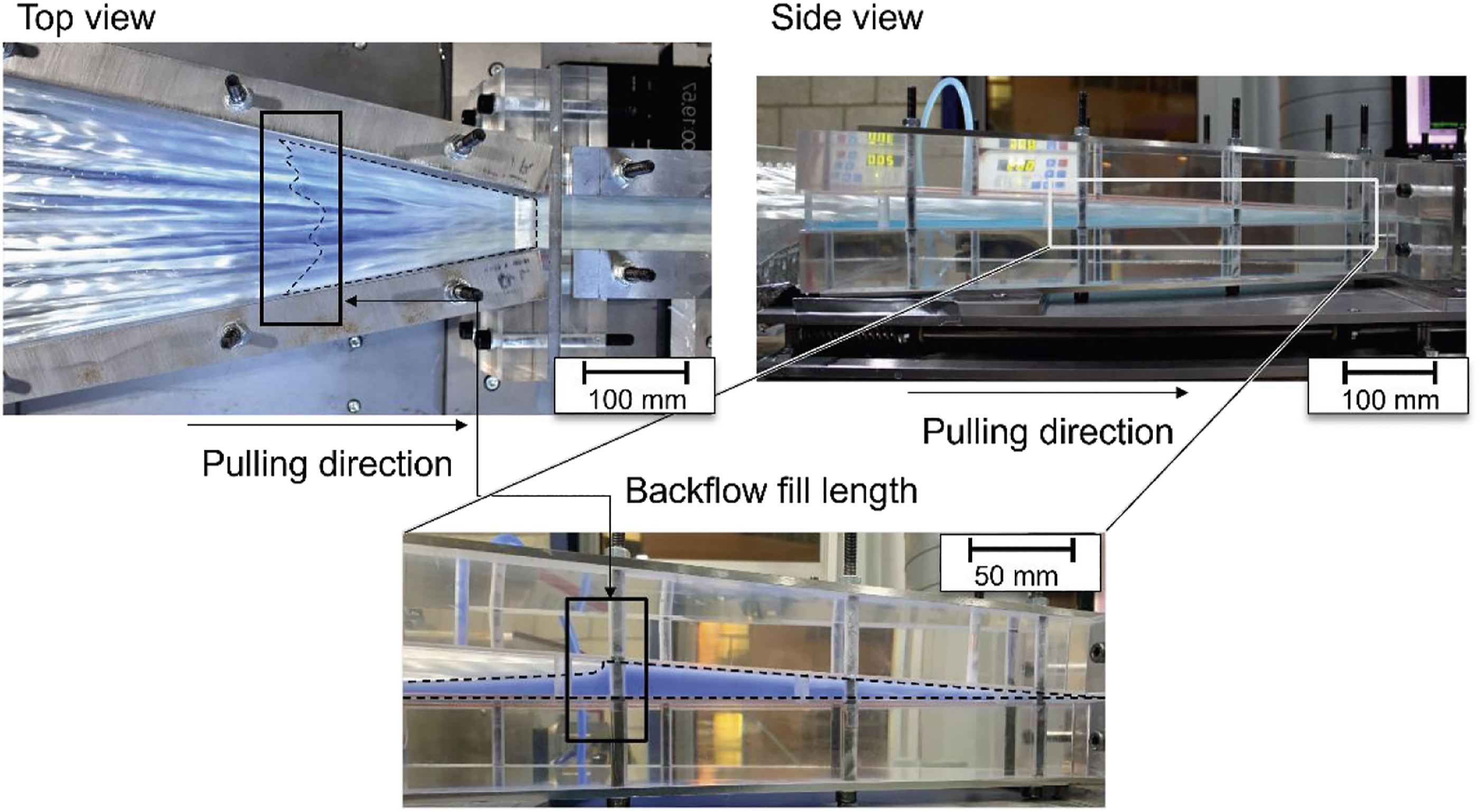
The images are analyzed regarding the backflow fill length, as observed from the top view, by a distinctively developed semi-automated image processing algorithm. Light refraction based on the PMMA plate is considered to have significant effect for fill lengths exceeding 350 mm and therefore is neglected in this study based on the available data. The algorithm reports the average backflow fill length and its standard deviation, indicating the shape of the flow front. The algorithm is implemented in the software MATLAB by The MathWorks Inc., Natick, USA, which provides a toolkit for image analysis.
The algorithm initially requires the user to identify the cavity edges in the image and is calibrated by the known width of the profile. Subsequently the algorithm uses different methods to automatically detect features of the flow front. The user can add or delete features manually to increase detection accuracy. Eventually, the backflow flow front is determined and averaged backflow fill length as well as averaged standard deviations are reported.
This algorithm yields a high repetitive accuracy for different users. Additionally, it can be reported about all investigated images that for each trial the standard deviations of the fill length means are smaller than the standard deviation of each respective image. Therefore, displayed values of backflow fill length for each process point result from the mean of the means and mean of standard deviations.
Based on the measured backflow fill length 
Evaluation of the pulling force
Pulling force, which is to be continuously overcome by the reciprocating grippers in order to keep the process going, is measured by mounting the transparent die on a sledge, which pushes on a force sensor. The process data is logged automatically and is analyzed regarding the pulling force. The subsequently presented pulling force values represent the average and respective standard deviations of pulling forces recorded over 30 s once a steady state is reached for a single process point.
Results
General visual observations of the flow field within the injection box
The transparent injection box enables a direct view at the flow field from the top. Figure 9 displays an exemplary comparison of one trial at different times. The first observation is that the flow front is evolving slowly and continually. Over longer time periods, it can be considered quasi-static. Furthermore, there is a significant amount of air bubbles that gather at the flow front and remain there during trials. Air bubbles initially appear close to the die entrance and move on the top cavity wall against pulling direction. Additional bubbles appear with further distance from the die entrance, probably originating in lower areas of the filling volume. They also increase in size with distance to the die entrance. Detailed observation of the time series yields variations in the emergence of bubbles especially towards the edges Additional qualitative observations, which are not displayed, include less air bubbles for lower pulling speeds as well as finer air bubbles for Mesamoll. Comparison of air bubble development for one exemplary process point (46 Rovings, SuS 5:3, 2.2 m/min) at different times.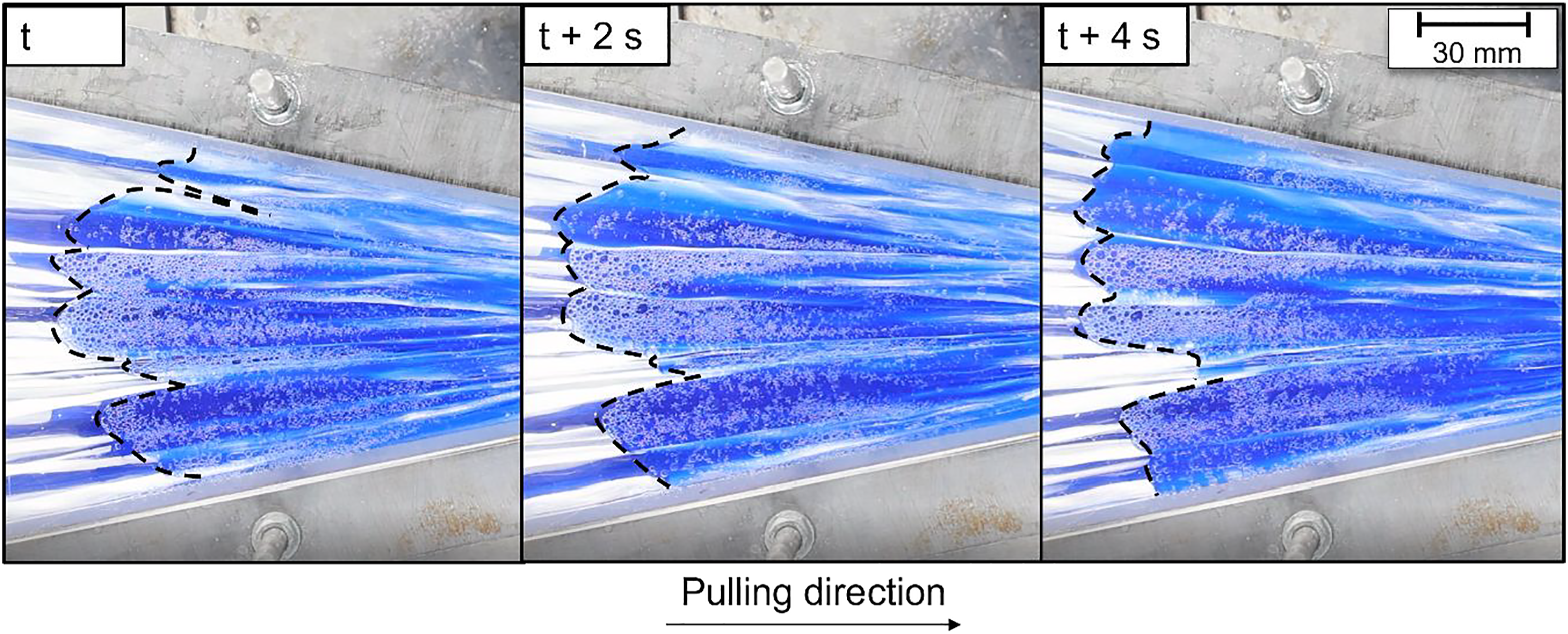
These observations illustrate that impregnation due to capillary forces does not lead to full impregnation, as air is trapped within the filaments and the fluid. This air is pushed out by increasing pressure closer to the final cross-section, which enhances impregnation quality. Subsequently, the air bubbles are transported against pulling direction by a combination of pressure gradient and buoyant forces.
Additionally, exemplary, qualitative visual and manual haptic investigations of the wet fiber bundle coming out of the die attachment were carried out, indicating that for all trials impregnation is achieved. Full impregnation and especially voids cannot be assessed with this setup.
Pulling force analysis
The development of pulling forces for the investigated sucrose solutions is plotted and linearly fitted for each mixing ratio in Figure 10. It can be observed that for each fluid with a different viscosity and each fiber volume fraction a good linear fit of pulling force and the dynamic contribution of pressure build-up, see section 3.2, is yielded. Increasing fluid viscosities result in a decreased slope of the fitted line. This difference in slope could origin from a multitude of effects, such as differences in pressure built up based on varying impregnation speeds or a different contribution mechanism of forces generated in the die attachment. Additionally, all configurations feature an above linear contribution of FVF on pulling force, as has been reported and is to be expected by the developed models.8,42,49,50 Linear fits of pulling force over dynamic contribution of pressure build-up for sucrose solutions of different viscosities.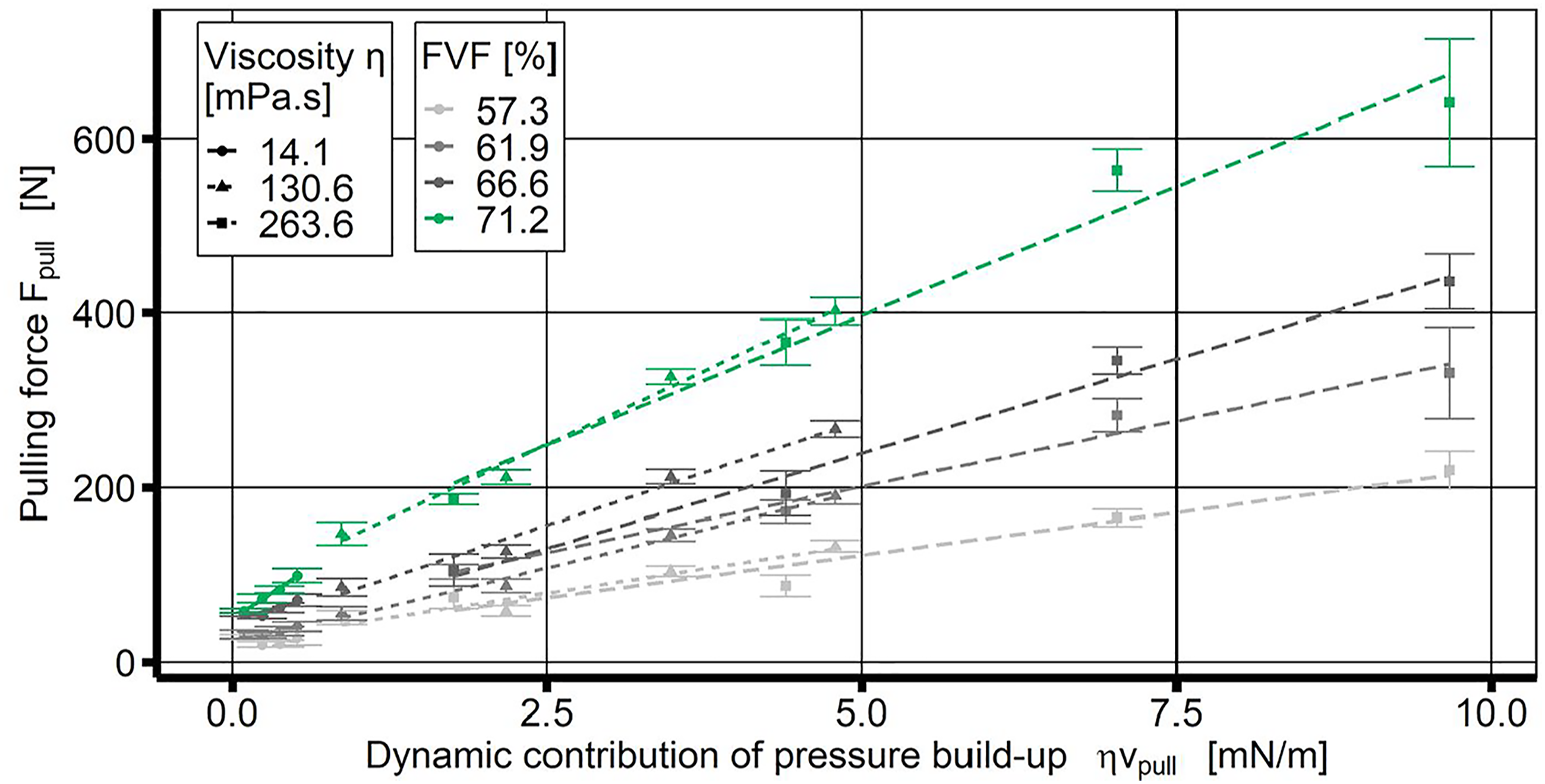
Figure 11, which displays the comparison of linearly fitted pulling forces over the dynamic pressure contribution for two different fluids of similar viscosity, visualizes that also for Mesamoll the pulling force is linearly correlated to the dynamic contribution of pressure build-up, which equals pulling speed for a constant viscosity. Similarly, as seen in Figure 10 an above linear impact of increasing fiber volume fractions on the pulling force is observed. Even though, the viscosity of the two materials is in a similar range, significantly different slopes are observed. In comparison with the results displayed in Figure 10, where increased viscosity leads to a flatter slope of the correlation, Figure 11 reveals the opposite effect. Mesamoll, featuring a slightly smaller viscosity than sucrose solution 5:3, displays a flatter slope of the correlation. The main difference between Mesamoll and sucrose solution according to the qualitative analysis is the wetting ability, see Materials, which indicates very good wetting ability of Mesamoll in contrast to sucrose solution. Based on this difference, an influence on pressure build-up based on the impregnation status is a reasonable explanation. Friction between single filaments in rovings could result in different compression and alignment behavior of the rovings, as friction is significantly reduced, when the fluid lubricates single filaments. Due to the multiple contributions to pulling forces the significance of this finding needs to be evaluated in more depth. Linear fits of pulling force over dynamic contribution of pressure build-up for different fluids with similar viscosity.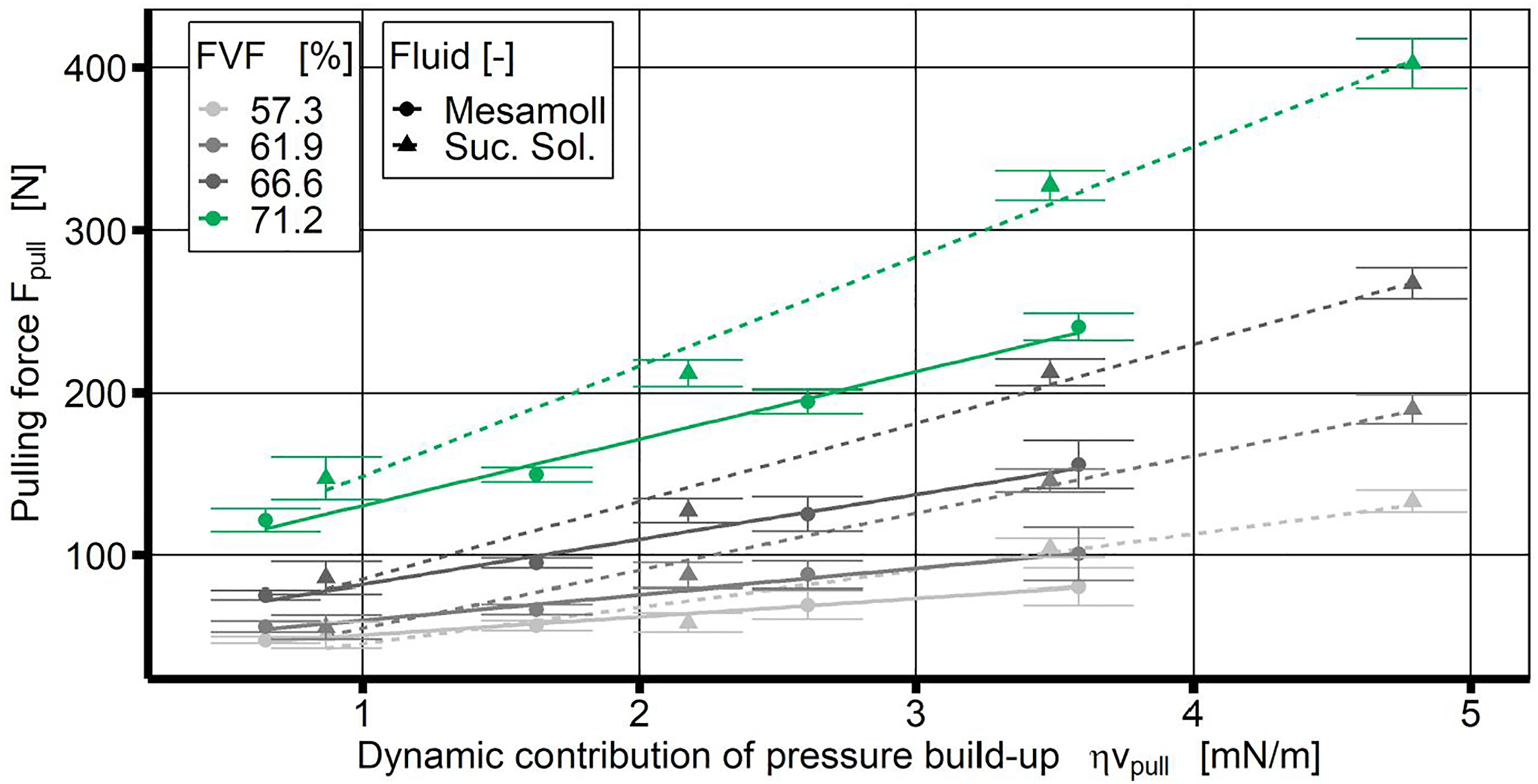
The observed linear correlation of pulling force and dynamic contribution to pressure build-up initially seems obvious, when considering equation (3) for pressure build-up and respective literature and models,8,31,42,51 but equation (4) for force contribution needs to be considered. Observing a linear correlation for this equation means, that a major part of pulling force development occurs in a distinctive area of the injection box with relevant pressure levels. The geometric factors of increasing gap height between rovings, which decreases dynamic pressure, and increasing surface area of the cavity envelope balance out to an approximately constant value. As the absolute change in cross-section area close to the die entrance is relatively small and local gap heights between rovings are minimal, it is likely for the relevant area to be close to the die. This behavior is generally consistent with implemented models for pressure build-up, which predict high pressures close to die and moderate pressures in areas of lower fiber volume fraction based on larger cross-sections.8,17,31 But a direct comparison is not possible due to no available pressure data in the cavity.
Quantitative analysis of backflow fill length
The results of the automated image analysis for the backflow fill length are plotted over the dynamic contribution to pressure build-up in Figure 12. For all investigated fluids, a similar behavior is observed. With increasing pulling speeds, which is represented by the different data points for a distinct velocity, the backflow fill length increases asymptotically. Even though, higher fiber volume fractions can be associated with larger backflow fill lengths, the absolute differences are rather small in comparison to the reported pulling forces. This behavior indicates a different governing mechanism for the determination of backflow fill length, whereas pressure build-up close to the die correlates with the upstream behavior. When considering equation (5), the backflow fill length is determined by the local upstream pressure equaling stationary pressure. This effect is most easily observed when comparing the backflow fill lengths of sucrose solution 5:3 (120.5 mPa.s) and Mesamoll (97.1 mPa.s). Sucrose solution 5:3 features an about 25% higher density and significantly shorter backflow fill lengths than Mesamoll, comparison Table 1. Additionally, it can be observed for the different sucrose solutions, that higher viscosities not necessarily lead to longer backflow. This is likely due to be a higher resistance to crossflows within the cut-plane perpendicular to the pulling direction, so that local gaps in the fiber planes have a smaller effect on pressure decrease upstream. Backflow fill length over dynamic contribution of pressure build-up for the highest and lowest fiber volume fraction.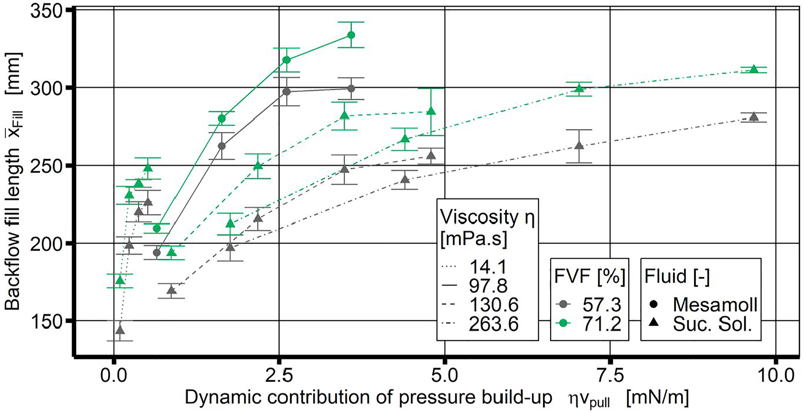
These observations are substantiated by the information displayed in Figure 13. This graph explores the correlation of dynamic pressure at backflow fill length, as calculated by equation (5), and respective pulling forces. The data displays an asymptotic behavior of the dynamic pressure at backflow fill length for the investigated parameters, indicating a diverging correlation of the two parameters, that roots likely in geometric factors as dynamic contribution of pressure build-up scales with both quantities. These results substantiate the distinction made in Figure 2, where at least two different flow fields need to be considered. Dynamic pressure over pulling force for different configurations identified by fiber volume fraction and dynamic contribution of pressure build-up.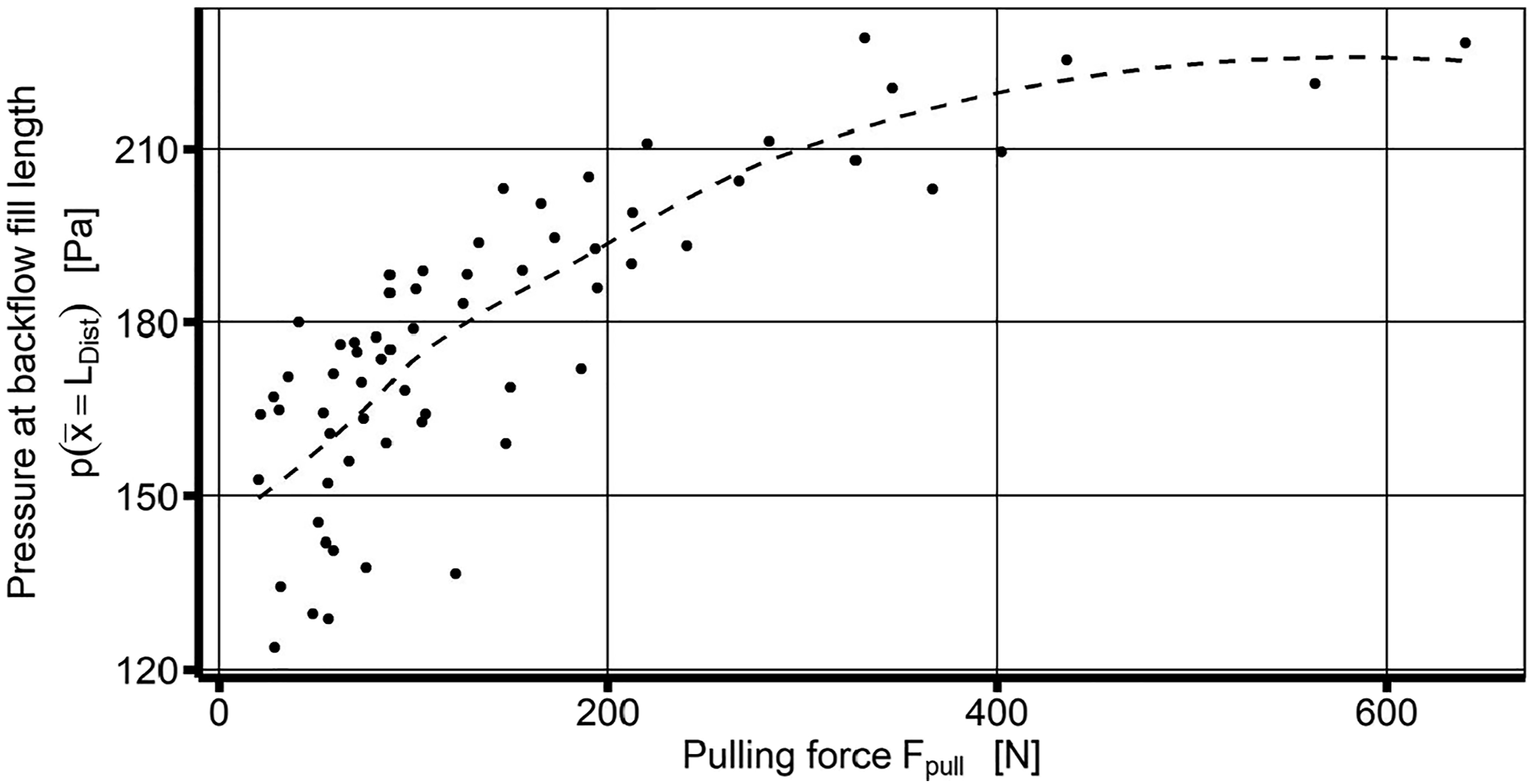
Development of resin residence time
Based on the results for backflow fill length displayed in Figure 12, the averaged resin residence time can be calculated according to equation (7). The resulting averaged resin residence times are displayed in Figure 14. It can be seen, that for the investigated cavity geometry the averaged resin residence time decreases with increasing pulling speed even though the injection box is filled with more resin. The observed times range from 10 min down to approximately 3 min, which provides a suitable window for many high-reactive resins at room temperature. Based on the observed non-linear correlation of viscosity and pulling speed with backflow fill length, this behavior indicates an opportunity to tailor the cavity geometry in order to manipulate the resin residence time, which can be a crucial parameter for highly reactive resins. Average resin residence times over pulling speed for different fluids.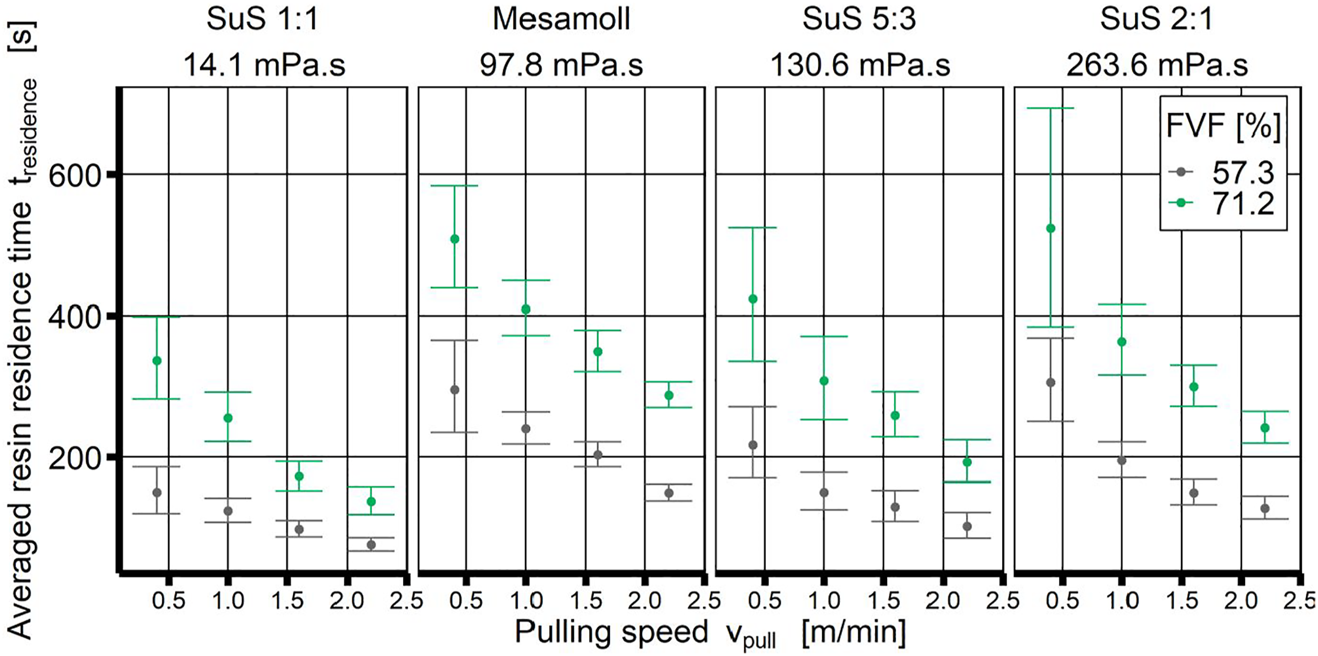
This evaluation does not include fluids upstream from the backflow fill length, which can be considered by an open-channel flow. Based on the tapered design, this volume is likely to have a relevant impact on averaged resin residence time. As this study intentionally overfills the cavity and excessive fluid gathers and mixes in this volume, no valid additional information can be gathered at this point.
Influence of additional guiding plates
In a subsequent step, additional guiding plates have been integrated in the setup between the final guiding plate and the fiber creel to reduce entanglements of rovings. Figure 15 illustrates the different configurations for the initial one guiding plate and the subsequent multiple guiding plates. Comparison of the fiber guiding system using one guiding plate in combination with a separating bar and multiple guiding plates.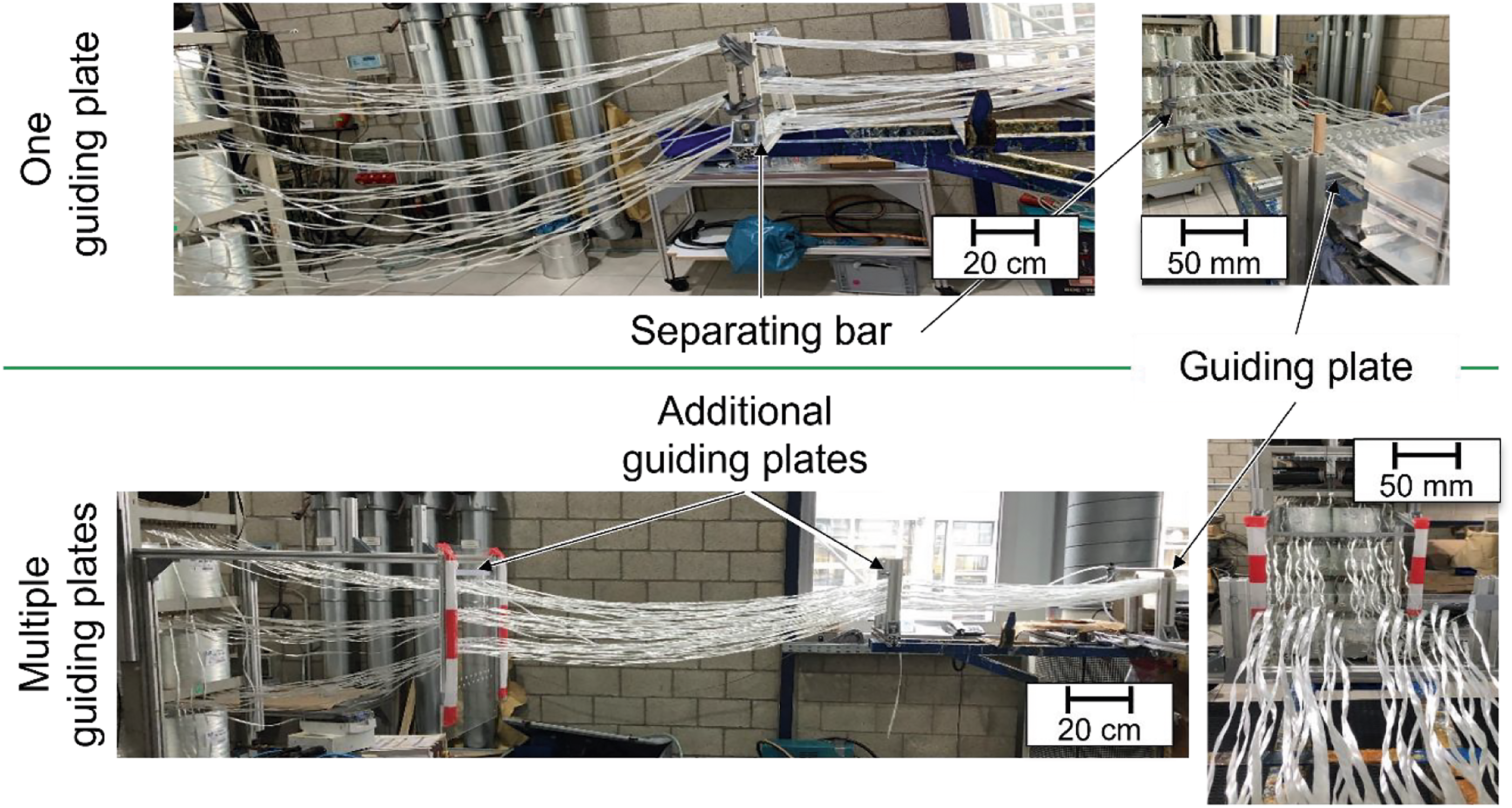
Figure 16 displays a comparison of measured pulling forces for the two different guiding plate configurations. It is observed for all investigated fluids, that the configuration of multiple guiding plates yields significantly lower pulling forces for all investigated parameters, which is also observed for the recorded pulling forces, when dry rovings are pulled through the setup at the start of trials. The observed significant differences can be explained best by the fact, that additional fiber guiding affects the cross-section form of rovings entering the injection box. With only one guiding plate between creel and injection box, the weight of the rovings induces an axial tension in the roving, which emphasizes a spreading effect, when the rovings are dragged through the hole of guide plate. When guiding the roving through multiple plates axial tension is reduced as the free length of path is shorter, which leads for the twisted rovings to form approximately a hollow tube. Based on these observations, significant impact on pressure build-up can be attributed to roving shape and resulting local gap development in the injection box close to the die. According to this, roving shape enables a significant parameter to manipulate pressure levels in the injection box. But it needs to be considered, that the hollow tube shape collapses when exposed to certain pressure levels in the injection box, which could result in a thicker textile to be impregnated. Linear fit of pulling forces over dynamic contribution of pressure build-up for different guiding plate configurations.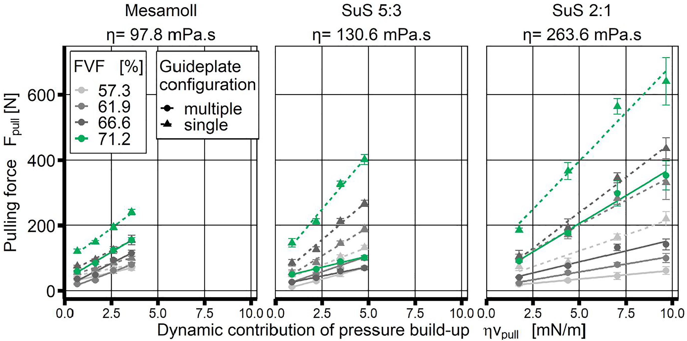
Figure 17 displays a comparison of the backflow fill length for both guiding plate configurations. Generally, a trend to higher backflow fill lengths for the single guide plate can be observed. There is no more distinct observation, emphasizing the observation mentioned before that pressure build-up at the die entrance only has minor effects upstream, as flow development is governed by different effects. Backflow fill length over dynamic contribution of pressure build-up for different fiber volume fractions under variation of guide plate configurations.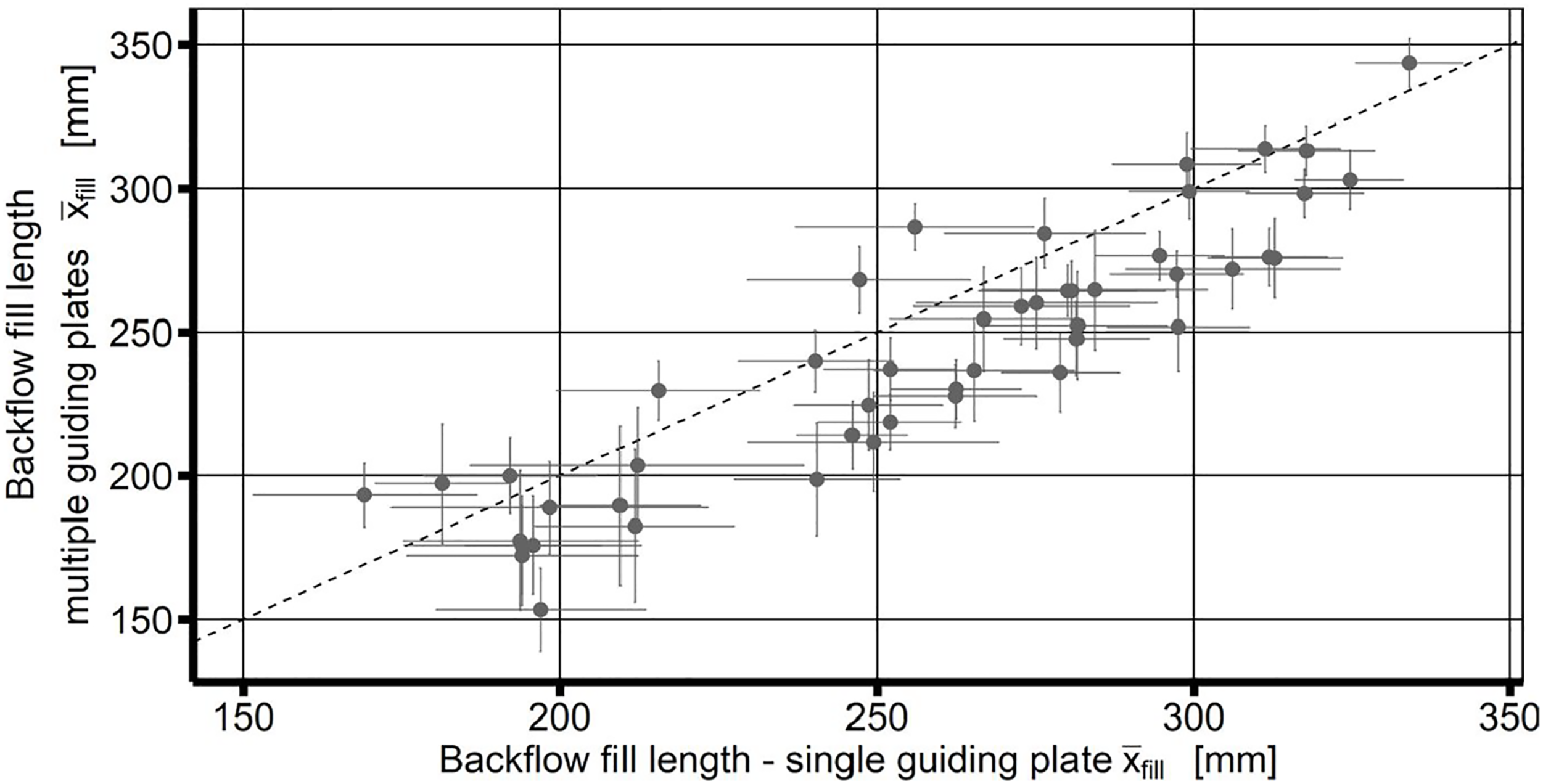
Conclusion
An experimental setup, integrating a transparent injection box that features a two-dimensional taper into a full-size pultrusion machine, is proposed. Systematic evaluations of the processing behavior of three independent process parameters, fluid, FVF and pulling speed, with two different guiding plate setups are carried out. Trial evaluation focuses on directly measured parameters, pulling forces and backflow fill length, but also elaborates derived quantities averaged resin residence time and dynamic pressure at backflow fill length.
Observations during trials indicate general impregnation for all investigated configurations. It is confirmed that pulling forces correlate linearly with the product of pulling speed and viscosity. Additionally, a significant impact of wettability on pulling forces is found as good wettability properties reduce pulling forces, which is attributed to the differences in gap formation between rovings due to filament friction and lubrication. Evaluations on visually assessed backflow fill length yield that backflow fill length and corresponding averaged resin residence time is not directly dependent on pulling forces, which are found to originate mainly from a small area close to the die. Resulting averaged resin residence times were found to range from 10 to 3 min, enabling the processing of many highly reactive materials. Interestingly, averaged resin residence times decrease with increasing pulling speeds.
Additionally, adding two additional guiding plates between fiber creel and final guiding plate was investigated and yielded major reductions on haul-forces. In contrast to that backflow fill length was reduced much less, adding to the point that backflow fill length and pulling force are not directly correlated.
Based on these results, the possibility of manipulating pressure build-up and resin residence time independently by taper angles provides the opportunity to tailor injection box cavity shapes for specific pultrusion products. Such a design relies on an accurate understanding of pressure build-up and a good understanding of impregnation behavior. The presented results show that an adequate representation of single roving shapes and positions is essential for deriving a scalable model of pressure build-up.
Footnotes
Declaration of conflicting interests
The author(s) declared no potential conflicts of interest with respect to the research, authorship, and/or publication of this article.
Funding
The author(s) disclosed receipt of the following financial support for the research, authorship, and/or publication of this article: This work was supported by the Parts of the presented research has been conducted within the research project (21090N) of the Forschungsvereinigung Kunststoffverarbeitung is sponsored as part of the “industrielle Gemeinschaftsforschung und-entwicklung (IGF)” by the German Bundesministerium für Wirtschaft und Energie (BMWi) due to an enactment of the German Bundestag through the AiF.