
Abstract
The failure properties of trouser-shaped tests on flexible composite called Uretek-3216LV were studied by experiment and theory. Based on the failure mechanical behavior of the trouser-type tests, theoretical model of the three stages (displacement, fiber stretching, and fiber breaking) were established. In the model, a spring system including the tail, tear del, and the fiber elongation is introduced to characterize the mechanical behavior of the displacement stage and the fiber stretching stages. Based on the strain wave model, the failure model of fiber breaking stage is established. Based on the trouser tearing tests and failure model, the trouser-shaped failure performance of flexible composites was analyzed in detail.
Introduction
Stratospheric airship (SSA) provides economic platform for reconnaissance and communication relay, which has attracted the attention of the world rapidly.1–3 Flexible film is the main material of SSA hull. The main function of flexible film is to prevent helium leakage, bear pressure difference between the internal and external, ultra-light radiation protection, and maintain the aerodynamic configuration.4,5 Single component material cannot satisfy the above requirements at present. Therefore, it is necessary to develop multifunctional composite materials. 6 In addition, the volume of large SSA is huge, 7 so the weight of SSA is heavy. In order to reduce the weight of airship, lightweight, high strength, and flexible composite is needed. As a kind of flexible composite material, laminated fabric composite has widely used in SSA envelope materials with its excellent mechanical properties. 3 Some flight tests of SSA with laminated fabric composite have been performed.8–10 Unfortunately, the flight tests failed due to the tear propagation of the flexible composite material. Therefore, it is necessary to study the tear properties of flexible composites.
There are many types of tear failure of flexible composites. Tear tests can be divided into two types: in-plane tear tests and out of plane tear tests. In-plane tear tests include the following tests: central slit tests,5,7,11–17 single edge notch tear tests, 18 trapezoidal teat tests,19–22 and wing-shaped tear tests. 23 The out of plane tear tests include the following tests: trouser-shaped tear tests.24–26
The central tearing test, an in-plane tear tests, is a common method to evaluate the mechanical properties of flexible composites. A large effort of work has been done to study the central tearing properties of flexible composites. Shoji Maekawa et al. 7 studied the central tearing properties of flexible composites by biaxial experiments and theories, which were in good agreement. However, it should be pointed out the failure theory is better in small size and worse in large size. Qu Zhipeng et al. 11 developed a novel model to predict the central tearing behaviors of flexible composites. Results show the novel model has good agreement with the tests under both large crack size and small crack size. In addition to linear cracks, other kinds of cracks had also been studied. 12 Ennouri Triki et al. 13 developed a criterion for textile structures based on the tearing energy. Results show the tearing energy is independent of sample configuration. Chen Jianwen et al.5,14,15 analyzed the central tearing property of the material from the perspectives of theory, experiment and simulation under uniaxial, biaxial central tearing tests. He Rijin et al. 16 studied the central tearing properties of flexible composites by experimental theory and simulation, and discussed the influence of different boundary conditions on the tearing strength. W. Dennery Freeston Jr et al. 17 developed a model to represent the crack propagation in woven fabric. Results show the high-modulus fibers woven into fabrics with shear stiffness can bear the larger applied load.
Apart from the above work, many scholars have made great contributions to the research progress of other in-plane tearing methods. Liu longbin et al. 18 developed a physics model to predict the tearing strength of laminated fabric materials with initial single edge notch. The trapezoid tearing method was studied by theory and experiment.19–21 Results show the tear strength was depend on the weaving density, failure strength, failure strain, and elastic modulus. In addition, some progress has been made in finite element simulation of trapezoid tearing. 22 Results show the trapezoid tearing strength of the coated woven fabric had little difference with the experimental result of uncoated sample. Beata Witkowska et al. 23 analyzed static tearing in cotton fabric for wing-shaped test specimens. A program for image analysis is employed to analyze tear propagation of the trouser-shaped specimen.
Large efforts of work have been devoted to the understanding of the tearing mechanism of flexible composite. N. A. Teixeira et al. 24 studied the “mechanism of tear” of acetate fabric by theoretical and trouser-shaped tear tests. In the theoretical model, the trouser-shaped tear specimens adopt springs to represent the tearing process. The spring system consists of three parts: the tail, the fiber stretch, the tear del zone. Results that the fiber stretch make a large contribution in tearing process. Zhang wen et al. 25 employed Ising model combined with the Monte Carlo simulation to study the trouser-shaped tear failure in coated fabrics. The theoretical model was effective to predictive the mechanical response of flexible materials. In addition, Wang et al. 26 reported the tear damage of woven fabric from experimental investigation and finite element analysis. Results show the finite element model has a good agreement with the tear tests. The friction coefficient, weaving structure, and weaving density are main influencing factors of the tear strength.
The tearing properties of flexible composites are reviewed and a lot of research results have been obtained. The research on trouser-shaped specimen is mainly focused on fabric materials. The tearing behavior of fabric materials in the failure process (including elastic stage and fiber breaking stage) is analyzed by using the spring system model. The elastic stage of fabric does not distinguish between displacement and fiber stretching stage, and the theoretical model parameters cannot be obtained. Therefore, the influence of all parameters on the tearing performance of fabric material cannot be analyzed in detail. The theoretical model of tear propagation has not yet been established in the fiber breaking stage of trouser-shaped fabric material. In this paper, taking fiber reinforced flexible composites as the research object, based on the theoretical model of trouser-shaped fiber samples and considering the strain wave model of central tearing fiber breaking, the tear theoretical model of the three stages (displacement, fiber stretching, and fiber breaking) is established and analyzed. The purpose is to study the failure behaviors of trouser-shaped on flexible composites by theory and experiment. The results can provide theoretical support for the design of flexible composite materials for stratospheric airships.
Experiment
Materials and specimen
The flexible composite called Uretek-3216LV is a multi-layer film lamination. The flexible composite material is mainly composed of Vectran fabric, polyvinylidene fluoride (PVF) surface layer, and various functional films. The areal density of flexible composite is 200 g/m2 with a thickness of 0.2 mm. The fabric is plain weave structure, its warp and weft intersect vertically, and the warp and weft density of the fabric is 17 × 12 pieces/cm, with warp and weft yarn fineness of 200 denier.
In Reference 1127, the mechanical properties of flexible composites under biaxial tension and central tearing were studied. The flexible composite studied in this paper is the same as that in reference 1127, so it will not be repeated.
The trouser-shaped specimen is designed according to the standard GB/T 3923.2–2009 (Textiles-Tear properties of fabrics-Part 2: Determination of tear force of trouser-shaped test specimens). Trouser-shaped tear specimen is shown in Figure 1. The length and width of trouser-shaped tear specimen are both 200 mm, the initial crack length is 100 mm. There are two groups of trouser-shaped samples, one is warp, the other is weft, each group has five samples. Trouser-shaped specimen (Units: mm). (a) schematic diagram of specimen size (b) trouser-shaped specimen.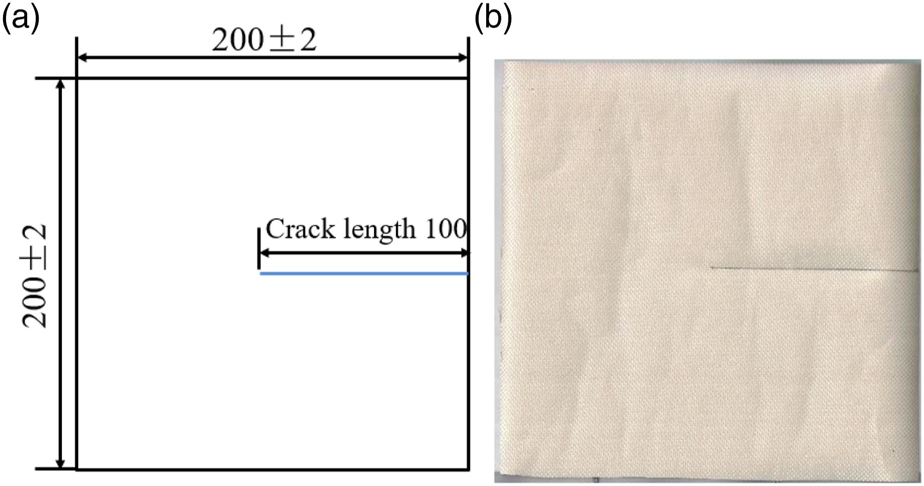
Environmental condition
All the tests were completed at a relative humidity of 65 ± 4.0% and a temperature of 20 ± 2.0°C.
Trouser-shaped tests
The tests were carried out on the WDW-100 test device, as shown in Figure 2. The limit load of the experimental equipment is 1 ton, the load control accuracy is 0.01 N, and the displacement control accuracy is 0.001 mm. The clamping region of flexible composite material needs to be strengthened to prevent the initial failure occurring in the clamped region. The WDW-100 test device.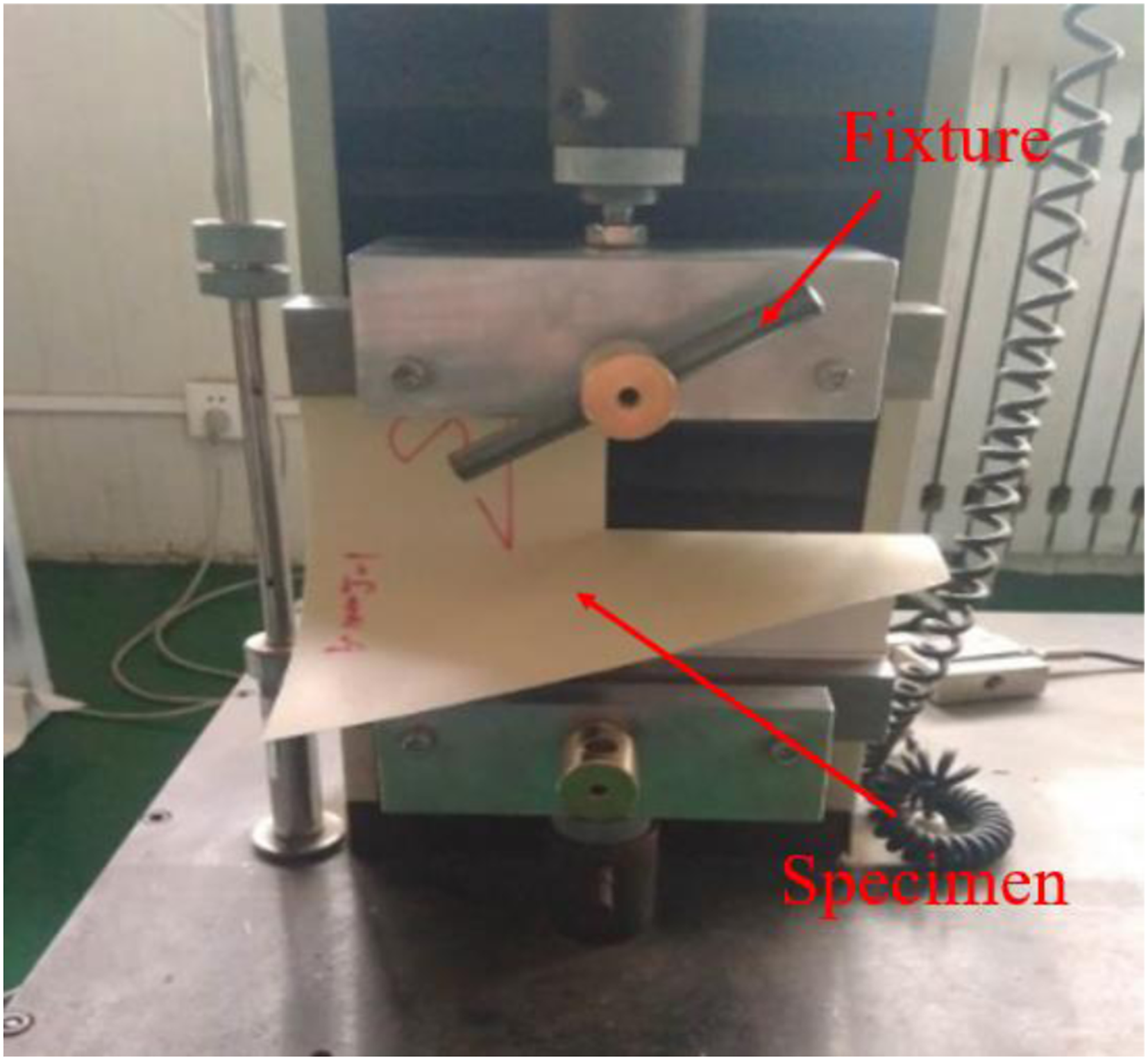
In the trouser-shaped tear tests, the displacement control mode was used, and the tensile speed was set as 100 mm/min. In the trouser-shaped tear process, the center points of the two clamps of the instrument must be in the stretching straight line. The fixture ends line should be perpendicular to the stretching line, and the clamping surface shall be in the same plane.
Trouser-shaped results
The load-displacement curves of trouser-shaped specimens is shown in Figure 3. In the symbol 100-warp, 100 represents crack length, and warp represents tensile direction. The load-displacement curves in warp and weft directions shows similar, the difference is the magnitude of the tear load, for convenient analysis, taking the 100-warp trouser-shaped specimen as an example for further analysis. The tearing load-displacement curves of trouser-shaped crack specimens.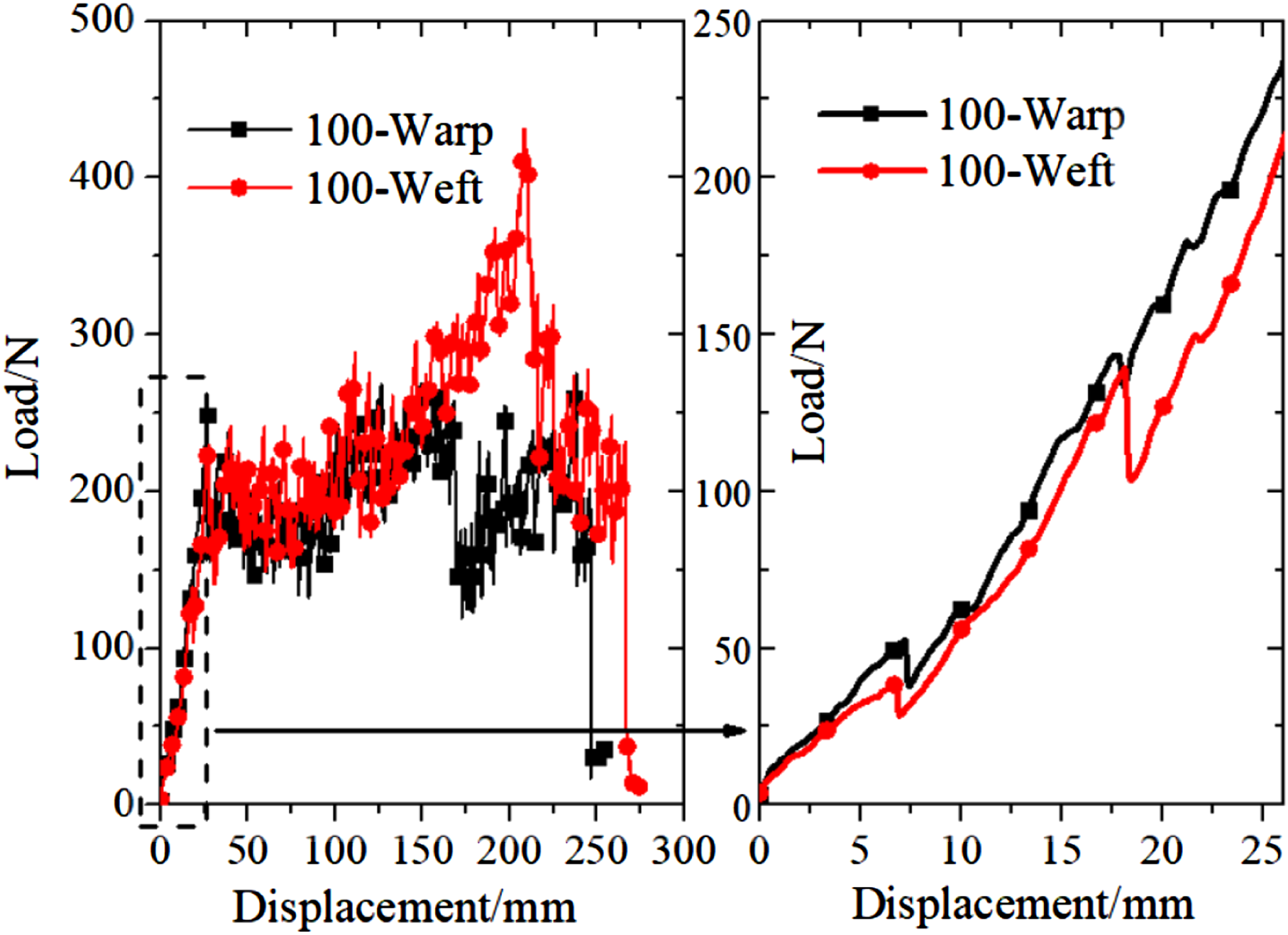
As shown in Figure 3, the load-displacement of trouser-shaped specimens show nonlinear. From the beginning of tension to the first fiber fracture load-displacement curve shows nonlinear. In the above stage, the tearing curve fluctuates, which may be due to the degumming of fiber and matrix. After the first fiber breaks, the load-displacement curves of the trouser-shaped sample fluctuate, which is mainly caused by the fracture of single or multiple fibers
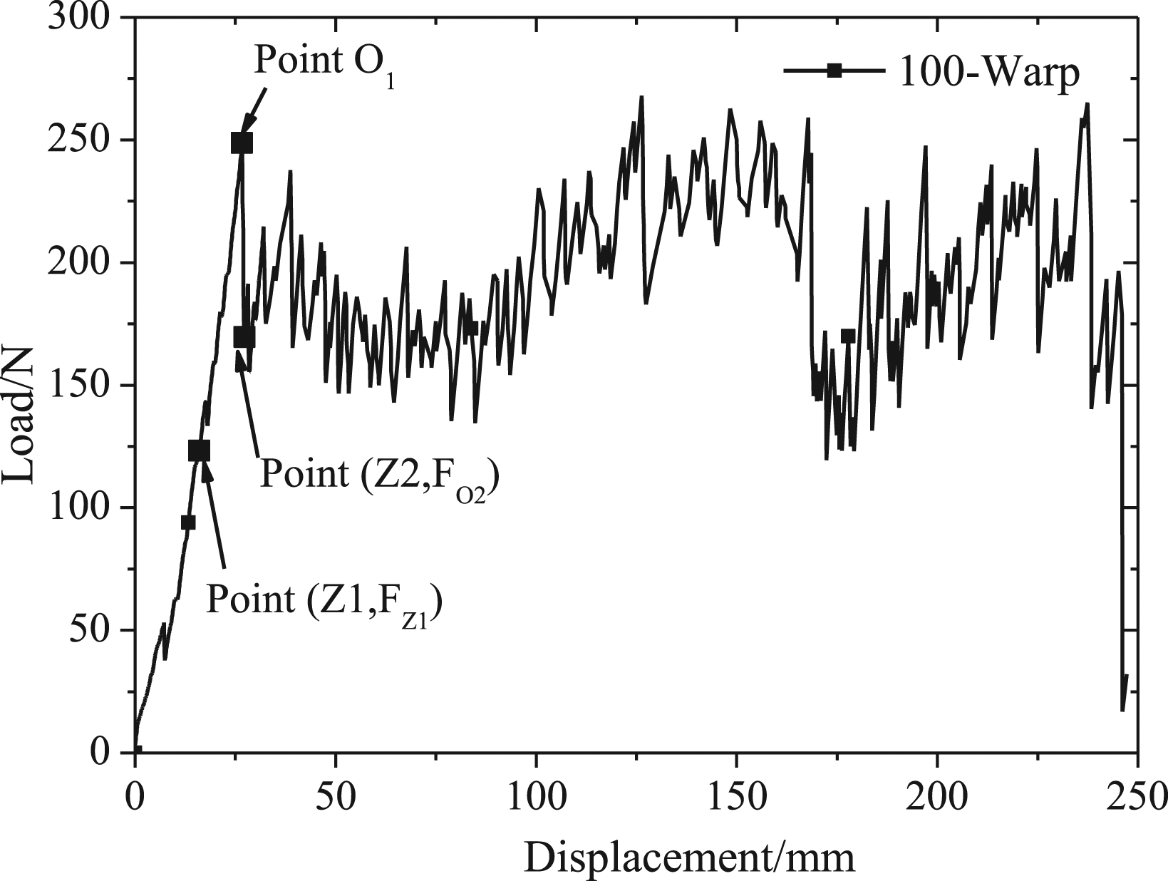
Considering some peaks are not tear peaks, therefore, it is necessary to judge the tearing peak in the tearing curves. Filter the tearing peaks in the tearing curve according to the standard GB/T 3923.2–2013. The tear load-displacement curve after filter is shown in Figure 4. In order to facilitate the subsequent theoretical analysis, some key points are marked on Figure 4. The points in Figure 4 correspond to those in Figure 5. The tearing load-displacement curve after filtering. Trouser-shaped tear process graph.
24
Theoretical model of trouser-shaped tear
Physical meaning of symbols.
Model of displacement stage
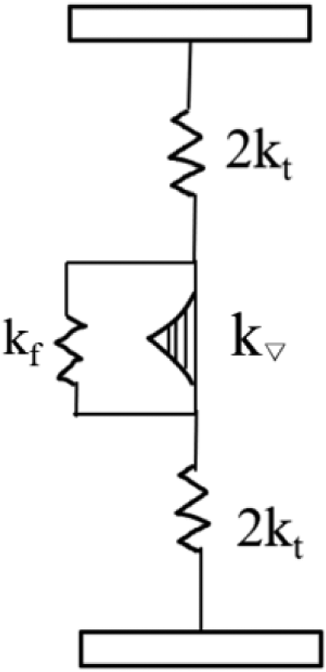
The displacement stage refers to the beginning movement of trouser-shaped specimen to the beginning of fiber elongation, which corresponding to the tear curve is O-Z1. Point O is the original point. The tensile displacement and load of trouser-shaped specimen at Z1 are 16 mm and 123N, respectively. In the displacement stage, the del zone appears at the crack of trouser-shaped specimen. With the further increase of tensile load, the tear del region increases. The trouser-shaped specimen bears two parts of load in this stage: the tail of the specimen and the tear del region. The mechanical properties in this stage can be compared with the spring system. The mechanical representation of the displacement stage is shown in Figure 6 kt and k▽ represents the spring constants of tail and tear del, respectively. Then the relationship between the total stiffness kd, kt, and k▽ can be expressed as follows Mechanical representation of displacement stage.
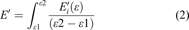
The unit of spring constants (kd, kt, and k▽) is N/mm. Considering that the tearing curves of the material are nonlinear in the displacement stage, it is assumed the total stiffness in the displacement stage is linear, so it is necessary to integrate the tearing curve to obtain the total stiffness in the displacement stage. Chen
27
proposed a formula based on the mean value theorem of integrals to calculate total modulus E’, as shown in equation (2). The unit of E’ is MPa, kd=Et, t is the thickness. The formula can calculate modulus in arbitrary strain range, and it is proven to have equal accuracy with the least square regression method
27
Model of fiber stretching stage
Fiber stretching stage refers to the stage from the beginning of fiber stretching to the beginning of the first fiber breaking. This stage corresponds to the Z1-Z2 segment in the tearing curve. The tensile displacement and load at the initial point Z1 of the fiber elongation stage are 16 mm and 123, respectively. The tensile displacement and load at the end point Z2 of the fiber stretching stage are 27 mm and 248N, respectively.
The mechanical representation of trouser-shaped tear at the stage of fiber elongation were analyzed in literature.
24
In the fiber stretching stage, the trouser-shaped specimen bears three parts of load in this stage: tail, fiber stretching, and tear del. Mechanical representation of displacement stage is shown in Figure 7 kf represents fiber stiffness. Components of stretching stage.
24
When the rigidity of the tail spring of the trouser-shaped tear specimen is zero, the rigidity of the trouser-shaped specimen k0 = kf + k▽. When the rigidity of trouser-shaped tear specimen is not zero, according to the analysis of mechanical properties, the mathematical expression of the total spring rigidity k is given as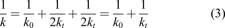
In order to obtain the mechanical parameters of the above three terms in the trouser-shaped tear specimen, further theoretical analysis is needed. Graphical representation was used for theoretical analysis in literature.
24
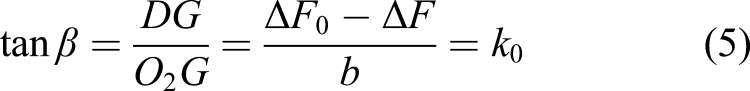
Graphical representation of components is shown in Figure 8. Graphic representation of spring system is shown in Figure 8(a). Trigonometric analysis of section from Figure 8(a) is shown in Figure 8(b). Graphic representation of components.
24
(a) graphic representation of spring system (b) trigonometric analysis of section from (a).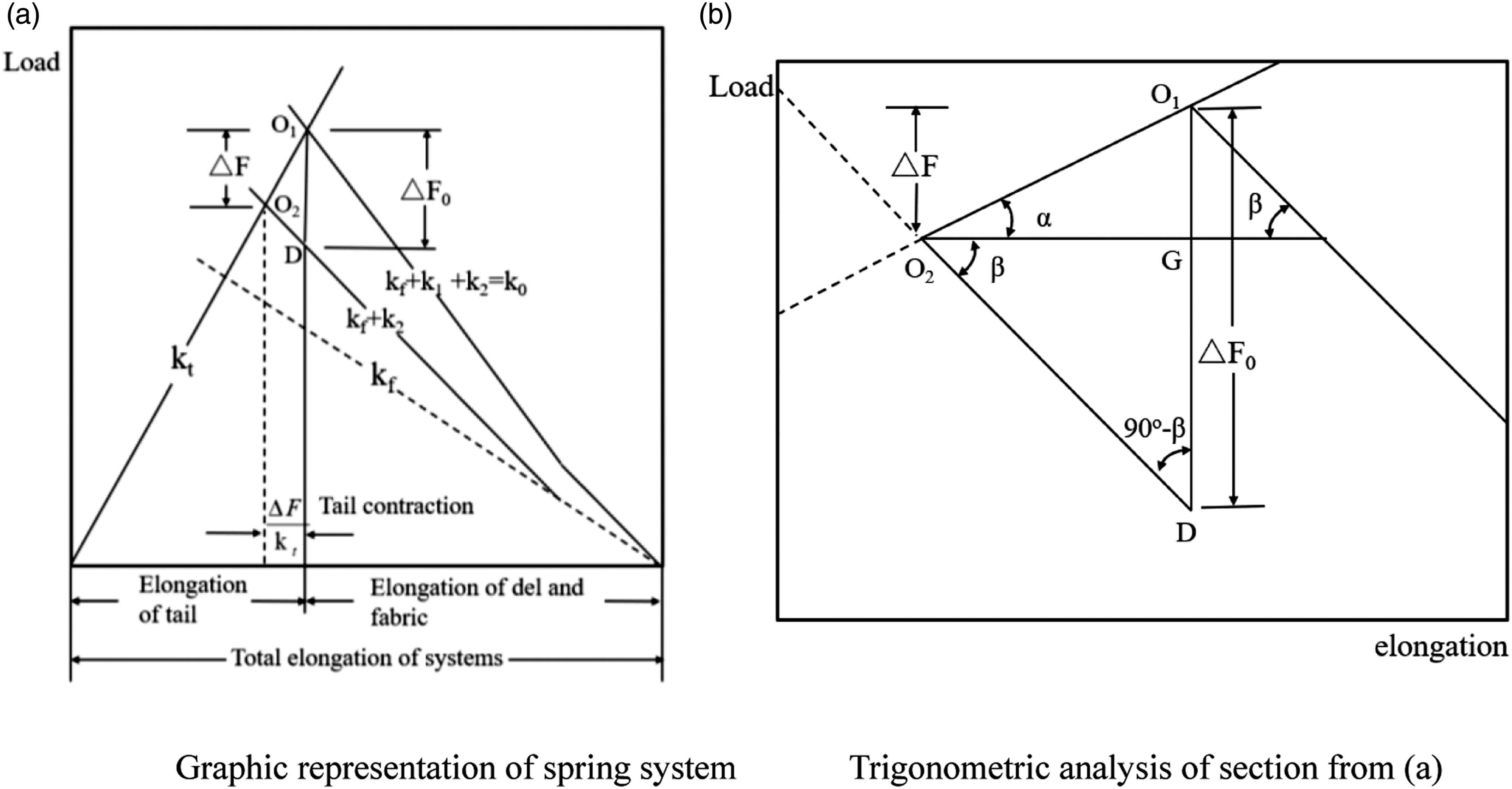
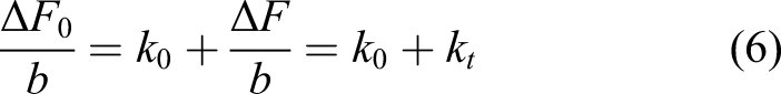
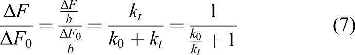
In Figure 8, the line marked kt is the load-elongation diagram of the tails, which is plotted using the origin at the left, while from the righted-hand origin the load-elongation diagram for the del and fabric in parallel with the del, k0, has been drawn. The k0 consists of kf (fabric), k1 (the first breaking yarns), k2 (the second breaking yarns). Since kf, k1, and k2 are in parallel, their load diagraphs can be added directly. Point O1 is the equilibrium just as the first yarn breaks. Point O2 is the new equilibrium after the first yarn breaks, the k0 become k0′, where k0′= kf + k2=k0-k1. The shift from O1 to O2 has taken place without any change in the total elongation. The following relationship can be obtained from Figure 8(b) b is the length of tail contraction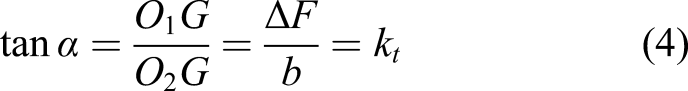
Model of fiber breaking stage
At present, the fiber breaking stage of trouser-shaped tear study judge and identify the tearing peak, and few literature have studied the law of fiber breaking propagation. W. Denney Freeston Jr
17
et al. used a one-dimensional strain wave theory to model the crack propagation of fabric center tear. In this part, the analysis method of literature
24
is used to model trouser-shaped tear crack propagation. In the theoretical model, the fabric can be approximated by a continuum. The strain of fabric is assumed to be period. Load diagram of trouser-shaped tear load is shown in Figure 9. Load diagram of trouser-shaped tear.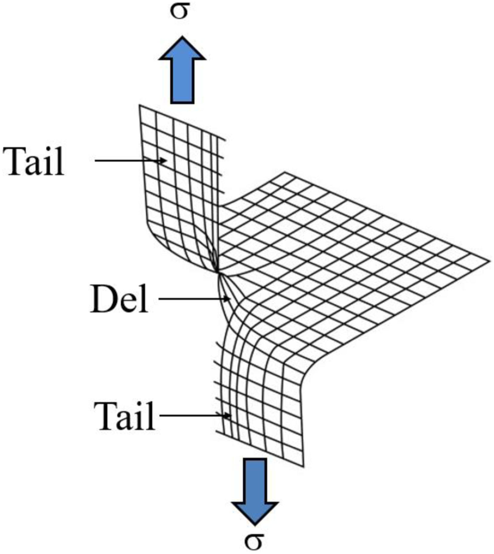
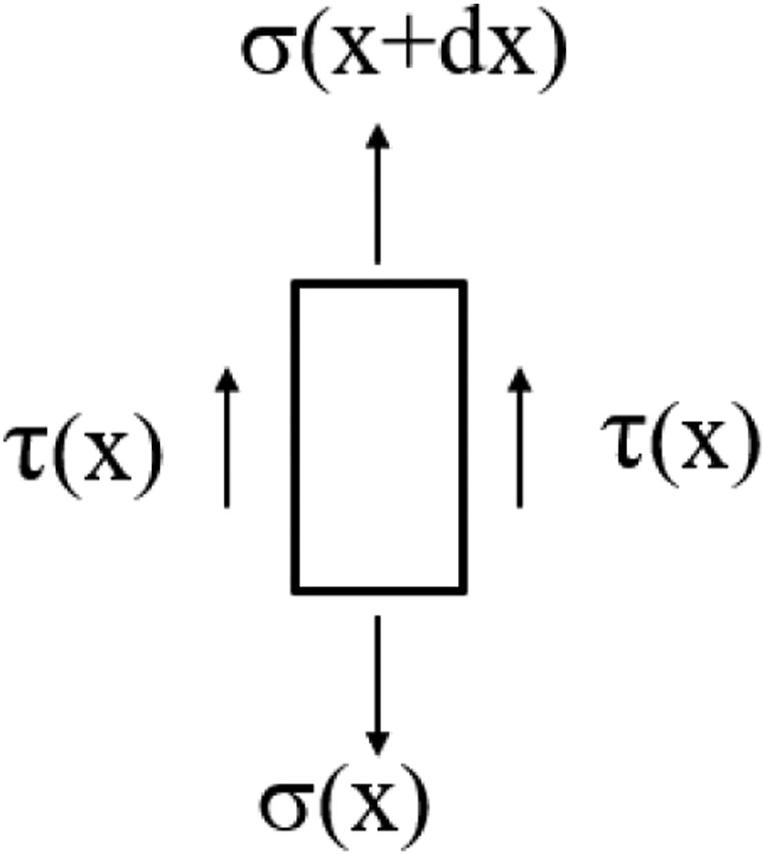
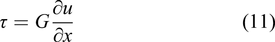
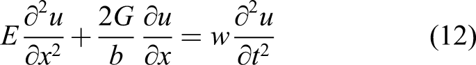
A one-dimensional model based on strain wave is analyzed. Load of fabric element is shown in Figure 10. Let σ is the axial force per unit width of fabric, τ is the shear force per unit length of fabric. a is areal density, b is the element width, and u is the displacement. The formula can be obtained by applying the Newton’s law Load of fabric element.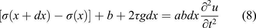
Let dx→0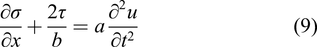
In addition to the equation of motion, the constitutive model is also required in equation (9). A linear elastic material is assumed. Therefore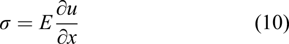
Letting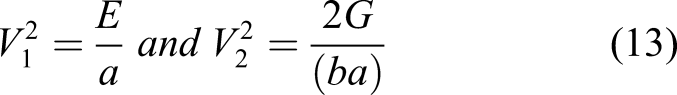
equation (12)can be written as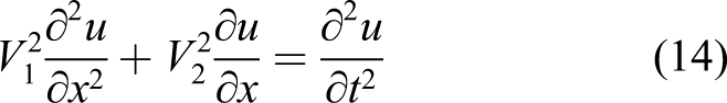
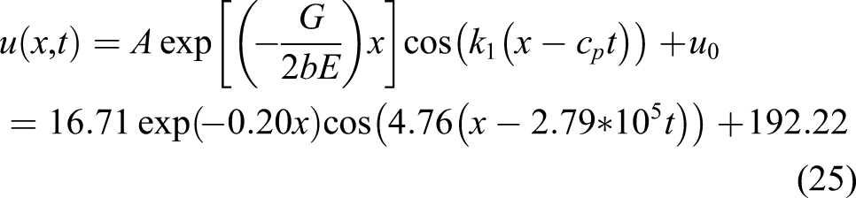
According to the characteristics of the equation, the displacement u (x,t) is given by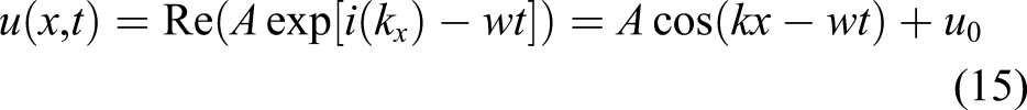

Let k=k1+ik2, equation (16) can be rewritten as
Since w is real, so is w2. Which means the imaginary part must be zero. The following express can be obtained
therefore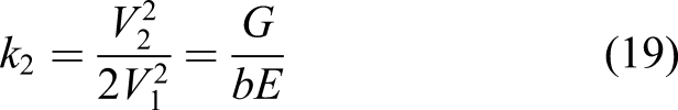
Substituting equation (19) into equation (17) gives the following formula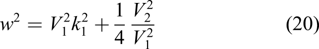
The displacement u (x,t) is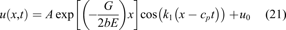
The phase velocity cp is given by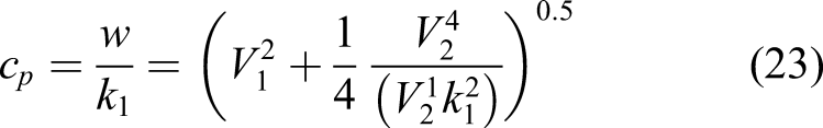
The group velocity cg is given by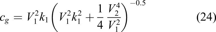
Results and discussion
The above section presents the theory of failure behaviors. This part mainly analyzes the failure properties of trouser-shaped tests by combining experiment and theory. The results of three stages (displacement, fiber stretching, and breaking) of trouser-shaped specimen were analyzed in detail and discussed. The mechanical parameters of the tearing process in the stage of displacement and fiber stretching need to be solved by the above two stages.
Mechanical parameters in the stage of displacement and fiber stretching.
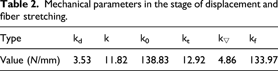
In the displacement stage, the total elongation is 16.07 mm. The extension of tail zone is 4.39 mm and the extension of del zone is 11.68 mm. The elongation of del region contributes most of the elongation of displacement stage, which accounts for 72.69% of the total elongation. The strain energy in del region also accounts for 72.69% of the total strain energy.
In the fiber stretching stage, the total elongation is 10.62 mm. The extension of tail zone is 9.71 mm and the extension of del zone is 0.61 mm. The elongation of tail region contributes most of the elongation of displacement stage, which accounts for 91.48% of the total elongation. The load of tail zone and total del zone are both 125N. In the total del zone, the load of fiber is 121N, and the load of del is 4.4 N. The contribution of del to fiber elongation can be negligible.
Mechanical parameters in breaking stage.
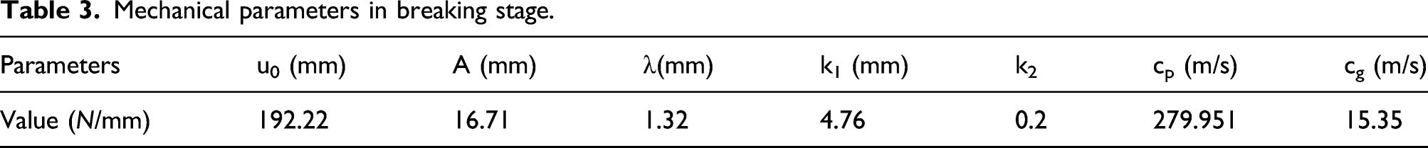
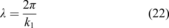
In the breaking stage, there are many factors that affect tear propagation. As can be seen from equation (25), the expression of displacement u (x,t) is decay. The displacement amplitude is related to G/E. The amplitude of displacement decreases with the increase of G/E. The width of fabric unit (b) also affects the amplitude of displacement. The amplitude of displacement increases with the increase of b. In addition, the period of displacement is proportional to k1, and k1 is inversely proportional to the wavelength λ. Therefore, the period of displacement is inversely proportional to wavelength λ.
Conclusion
The failure properties of trouser-shaped specimen were studied by theory and tests. The results can provide theoretical support for stratospheric airship design. The conclusions were summarized as follows:
A large strain nonlinear failure model was developed. A spring system composed of the tail part of the sample and the tearing triangle area was introduced to characterize the mechanical properties of the displacement stage. A parallel spring system composed of tearing triangle and fiber elongation was introduced, which was connected with the tail of the sample, to characterize the mechanical properties of the fiber in fiber stretching stage. Based on the strain wave model, a failure model of the fiber breaking stage was established.
Based on the failure model, the failure properties of trouser-shaped specimen were analyzed. The results show that in the displacement stage, the fiber and matrix in the tail of the sample play a major role in the failure performance; in the fiber stretching stage, the fiber play a major role in the failure performance; in the fiber breaking stage, increasing the ratio of shear modulus to elastic model can prevent crack propagation.
Footnotes
Declaration of conflicting interests
The author(s) declared no potential conflicts of interest with respect to the research, authorship, and/or publication of this article.
Funding
The author(s) disclosed receipt of the following financial support for the research, authorship, and/or publication of this article: This work was supported by the Young Key Teachers Projects in Henan Higher Education Institutions (Grant no. 2018GGJS113),Science and Technology in Henan Province (Grant no.222102220069 and 222102220030), the Program for Innovative Research Team (in Science and Technology) in University of Henan Province (Grant no. 20IRTSTHN016) and the National Natural Science Foundation of China (Grant No. 11802334).