
Abstract
This paper presents a novel experimental and computational approach to characterize fracture behavior of the intermetallic bonding layer (IMBL) in bimetallic bearing materials. The proposed methodology is applied to tin (Sn) based Babbitt alloy/mild steel bimetallic composite. In this study, macro stress–strain behavior of the bond under tensile-shear stress was calculated by considering the local shear surface geometry instead of the apparent bonding zone. The metallurgical bonding layer failure mechanism was identified from the scanning electron microscope (SEM) observations of the fractured IMBL of the bimetallic samples tested in tension-shear. It has been found that a damage mechanism of ductile nature was the cause of tearing of the IMBL. The coupled elasto-plasticity and damage constitutive equations for the IMBL were formulated and implemented based on SEM observations. Characterization of the shear fracture behavior of IMBL included FE numerical simulation of tensile-shear tests of the bimetallic composites. Consequently, a calibration methodology is proposed to estimate the IMBL fracture parameters. This proposed approach validation was based on a qualitative and quantitative confrontation between the experimentally measured shear force-displacement diagram and the numerically calculated diagrams obtained from the simulated IMBL. Commendable average quantitative errors of almost 1% are achieved in terms of yield strength, ultimate strength, and elongation at break between computed results obtained within sheared regions of the simulated Babbitt/steel (Sn – IMCs) BL and experience. The results of such a confrontation are promising for the application of the proposed approach to predict fracture during the forming of bimetallic composite materials.
Keywords
Introduction
Development of new materials with multifunctional physical properties are critical for the manufacturing industries. Global environmental challenges and increasing demand of the limit energy resources are one of the key drivers. In addition to that, there is growing need to minimize the use of rare and expensive metals in the metallurgical industries. This can be attained by engineering a single layer structure into a multi-layer metal composite structure in which each layer provides a distinct set of physical properties. The multi-layered metal composites, including bimetallic composites, have several industrial applications such as automotive, aerospace, and chemical pressure vessels due to the unique properties of each metal at a reasonably low cost.
Several studies have investigated the processing of bimetallic materials.1,2 During manufacturing of the dissimilar metal components, for instance steel/aluminum, aluminum/copper, stainless steel/carbon steel, steel/titanium etc., metallurgical bonding interface or intermetallic bonding layer (IMBL) is critical for joint integrity. The interface formation mechanism and microstructure are key considerations during bimetal composition manufacturing.3,4 The ultimate goal is to manufacture bimetals with strong adhesion over the whole interface and to enhance formability of bimetallic composites.5–7
Generally, the bimetallic composite products are processed either by centrifugal casting, cold rolling, and diffusion bonding or hot–roll bonding techniques. They are sometimes further processed by bending, deep drawing, and cutting processes to continue their manufacture into finished products. However, it is well recognized that the bonding interface represents a serious source of weakness inside the bimetal such as interface cavities and inclusions.8,9 Interfacial joining strength is influenced by several factors such as ratio of strain reduction, roll speed, bonding temperature, and interfacial oxidation. 10 As a result, formability and in-service performance behavior of the bimetallic components is compromised.9,11,12 In that regard, Suresh et al. 12 studied fatigue crack propagation behavior in the vicinity of the interface of stainless-steel clad plates and reported that a strong interfacial joining strength is required to prevent the interfacial delamination during impact testing, bending, and certain in-service processes. Rajhi et al. 11 studied the U-bending of Al-Sn bearing alloy/mild steel bimetallic composite employing a high-speed camera and characterized the fracture behavior of the intermetallic bonding layer using continuum damage mechanics (CDM) theory. Atrian et al. 13 investigated wrinkling and fracture during the deep drawing process of steel/brass laminated sheets besides to the effect of the process parameters such as friction.
Nevertheless, while it is essential to continue to accumulate experimental data, it is equally important to take advantage of FE modeling to characterize the mechanical behavior of the material created at the IMBL. Research in this aspect by FE constitutive modelling using plasticity theory and damage mechanics remains largely unexplored especially for the bimetallic materials. This requires the implementation of constitutive behavior laws to appropriately describe the mechanical behavior of the IMBL material in addition to the two base materials of the bimetal.
Alternatively, most of the FE modeling research works that focus on the study and optimization of bimetal forming process have been observed omitting the IMBL because of the lack of information on the constitutive laws of the metallurgical bonding layer.6,13–16 Li et al. 17 numerically investigated the interfacial failure behavior of a stainless steel/carbon steel bimetallic plate under uniaxial tension test employing a 3D FE model involving five material types. In their study, three different materials were assigned to the intermetallic bonding layers, but without providing any clear information regarding the constitutive modeling of the IMBL. A numerical analysis of a high temperature extrusion process applied to bimetallic tubes made of two pre-bonded metallic materials with different plastic properties has been presented by Alcaraz et al. 14 To predict fracture during the extrusion operation, they used in their FE modeling a parameter related to the void growth rate at the interface with a failure criterion, however, without explicitly considering the mechanical behavior of the material in the joining interface.
Fundamentally, it is unrealistic to ignore the metal at IMBL in the design and modeling of the layered materials. Thus, it is important to account for the effect of damage on mechanical behavior of the metallurgical bonding layer. Therefore, the FE numerical simulation of pre-bonded composite components fracture during their processing requires sophisticated constitutive modeling for the IMBL.
In this work, a novel experimental–numerical approach has been proposed to characterize shear fracture behavior of the IMBL in bimetallic materials. Such a methodology is applied to the Sn based Babbitt alloy/mild steel bimetallic bearing materials. The main goal is to determine the constitutive model parameters of the material in the interfacial region by considering the effect of the cast Babbitt alloy and the mild steel substrate. These parameters could be exploited to predict fracture behavior of pre-bonded bimetallic materials during processing for the aim of optimizing formability and improve in-service performance.
Experiment
Bimetallic composite material processing and manufacturing
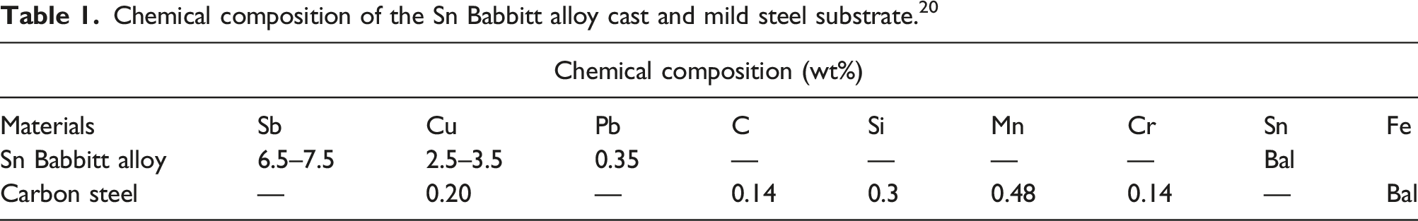
Chemical composition of the Sn Babbitt alloy cast and mild steel substrate. 20
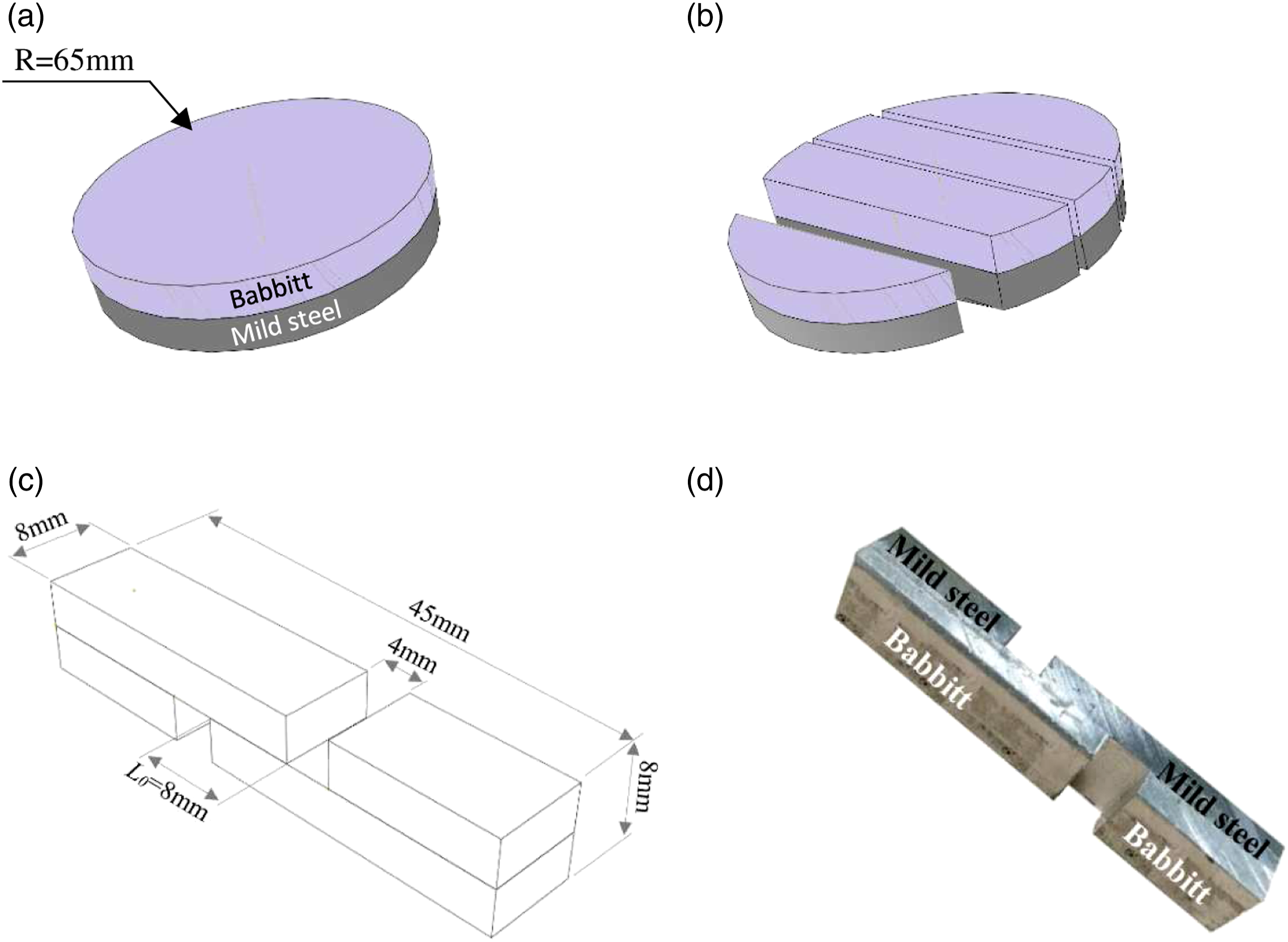
(a) Babbitt/mild steel raw sample illustration after casting and solidification process, (b) Sliced raw samples, (c) Geometry of tension–shear bimetallic specimen (ASTM D1002) with L 0 is the lap length: the apparent length of the studied bonding region, (d) As-prepared Babbitt/mild steel tension–shear bimetallic specimen. II-2 Assessment of the Babbitt alloy/mild steel IMBL thickness.
During the bimetallic sample preparation process for microscopic examination of the Sn Babbitt alloy/mild steel IMBL, the external surface located at the central region of the Babbitt–mild steel bimetallic sample is grinded, polished and etched using a solution of 4% Nital (96% ethanol alcohol and 4% nitric acid HNO3). Subsequently, scanning electron microscope (SEM), a field emission gun is used to assess the IMBL thickness and morphology. It has been reported that by employing a mixture of pure tin (Sn) and flux in the tinning process, the interface microstructure of bimetal casting displays in general thin interfacial layer composed of tin (Sn).
18
Figure 2(a) shows metallographic structure of babbitt alloy and the interface as located within the bimetallic composite between the Babbitt and mild steel. Whereas a thin layer of almost continuous Sn-intermetallic compound layer (Sn – IMCs) of about 5 μm appears at a higher magnification as shown in Figure 2(d). EDS spectra and elements analysis of the bimetallic composite material including the intermetallic compound layer are shown in Figure 2(b)–(f). SEM of Babbitt/steel bimetallic composite illustrating (a) Bonding interface of Babbitt/steel bimetallic composite, (b)&(c) EDS spectra and elements analysis of points 1&2 marked in Figure 2(a), (d) Babbitt/steel (Sn – IMCs) BL at higher magnification, (e) Line scan results across the interface (L1 in Figure 2(d)), (f) EDS spectra of points 3 marked in Figure 2(d).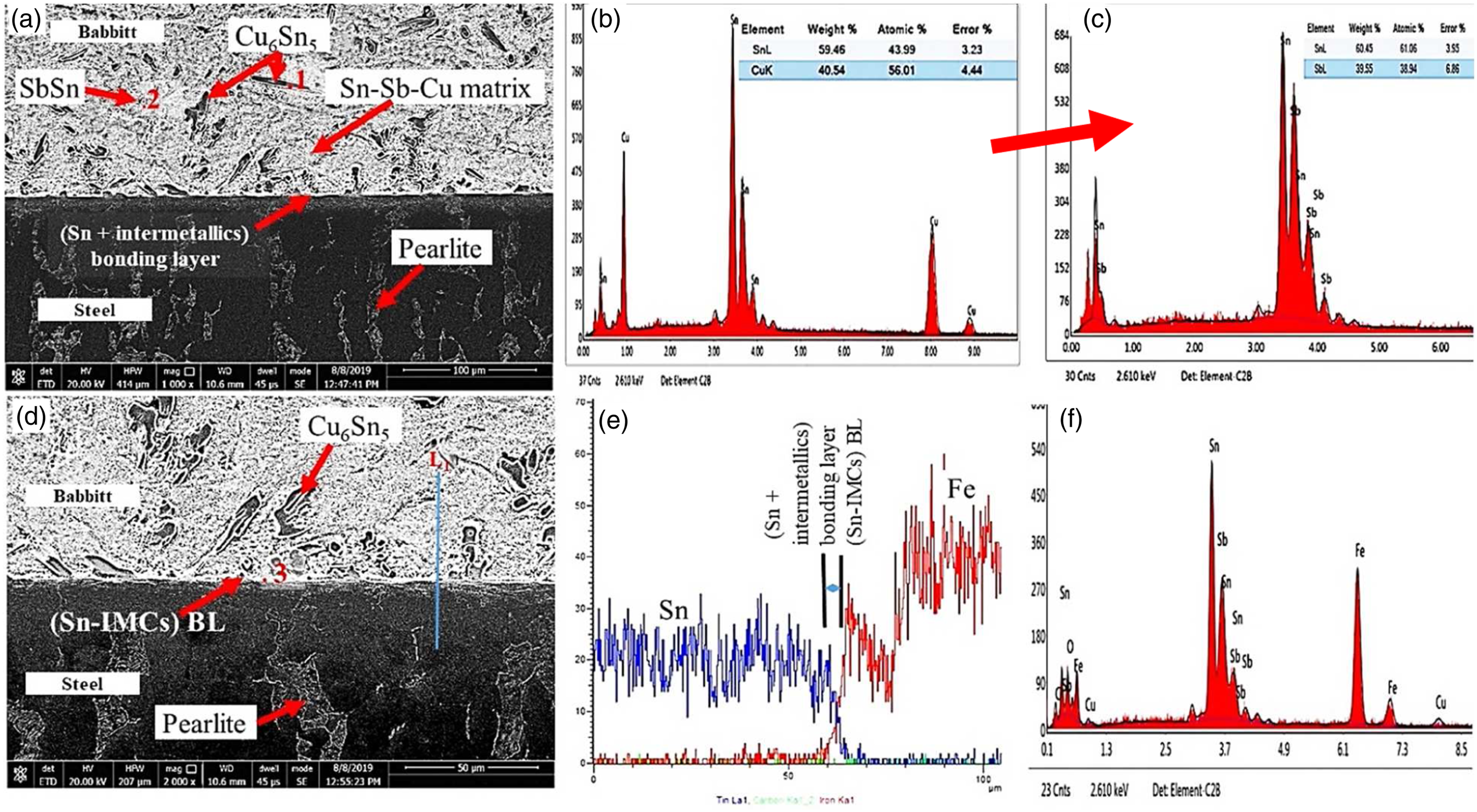
Mechanical characterization of Babbitt/steel (Sn – IMCs) BL
The manufactured tension–shear specimens given in Figure 1(d) were loaded in uniaxial tension testing up to failure. The tension testing of the tension–shear samples also called tension–shear testing is a technique widely used to investigate the shear behavior of the IMBLs in bimetallic composite materials. In this study, the tension–shear tests were carried out by means of a universal tension testing machine Instron® 5969 equipped with a tension load cell of 50 kN capacity. The tension–shear specimens were loaded at constant crosshead displacement rate of 1 mm.min−1 so that pulling is being applied to the bimetallic specimen side where longest portion of the Babbitt metal is placed (Figure 3(a)). Figure 3(a) illustrates the bimetallic specimen with Babbitt metal component designations as positioned in the grips of the tension testing machine. A small clip–on extensometer fully dedicated for strain measurement of an adhesive under shear loading of 8 mm gage length and of about 16 mm travel distance is used. The extensometer is equipped with removal system and placed onto the bonding area of the longest Babbitt section and employed until the yield point of the Babbitt/steel (Sn – IMCs) BL material. Several samples were tested until total failure and the tests which display failure event without bimetal sample debonding were excluded from the investigation. Note that bimetallic specimen debonding or detachment means total separation of the Babbitt–mild steel bimetallic composite lips at the center of bimetallic specimen by complete failure of the (Sn – IMCs) BL under shear loading. Figure 3(b) shows the shearing global response of the Babbitt/steel (Sn – IMCs) BL material represented by two retained global force–displacement diagrams. These global responses are arisen from the tension–shear tests (test 1 and test 2) displaying debonding failure events. Figure 3(b) proved that the (Sn – IMCs) BL material exhibits obviously elasto–plastic behavior and a ductile failure mechanism. Figure 3(c) illustrates bimetallic sample debonding and fracture as observed at the end of the tension–shear test 1 due to total failure of the (Sn – IMCs) BL under shear loading. (a) Illustration of Babbitt–mild steel tension–shear bimetallic specimen as placed between the grips of the tension test machine, (b) Tension–shear global force–displacement diagrams of Babbitt/steel (Sn – IMCs) BL obtained for two selected tests displaying failure event by total debonding of bimetallic sample, (c) Fracture of bimetallic sample by complete failure of Babbitt/steel (Sn – IMCs) BL as observed at the end of tension–shear test 1.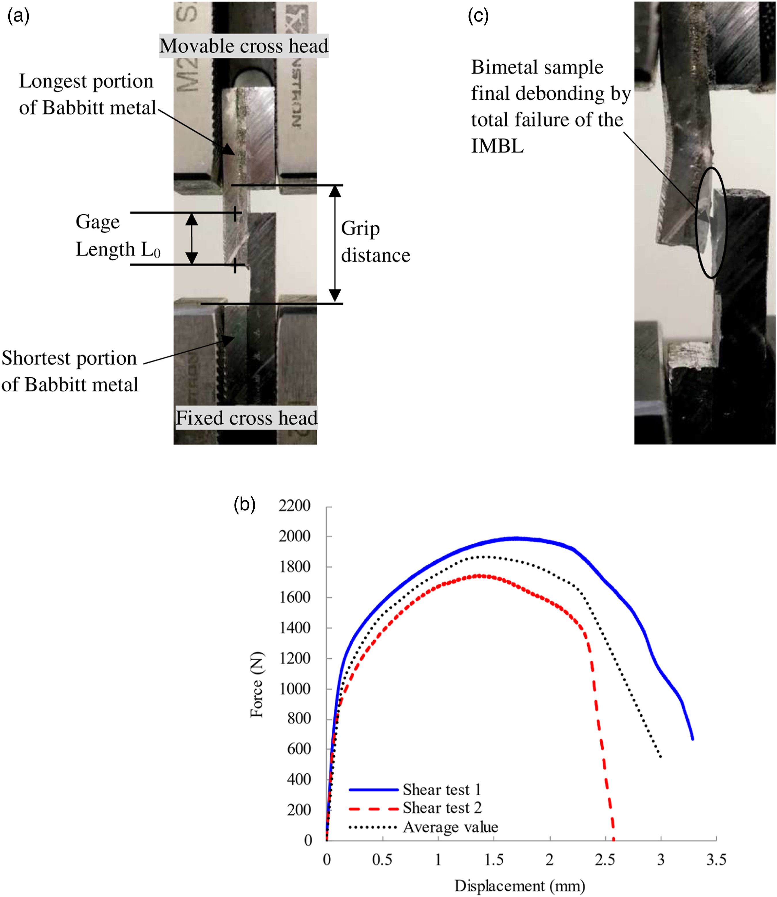
However, Figure 3(b) shows a significant fluctuation in the achieved maximum loading and displacement at failure values for the two tested Babbitt–mild steel tension–shear bimetallic samples. Contrasts in terms of maximum loading and displacement at failure between tests 1 and 2 of 13% and 20% were recorded, respectively. The dissimilarity in the global mechanical behavior (Figure 3(b)) was expected but should not be transmitted to the local mechanical behavior represented by the stress–strain response of the Babbitt/steel (Sn – IMCs) BL material.
Considering the isotropy of elasto-plastic behavior of the IMBL material, stress–strain response of bond material should be unique before softening starts to take place. The discussion below will focus on this matter.
Indeed, different factors that may coexist are responsible for such fluctuation. The unpredictability of maximum force and displacement at failure values is plausible as the IMBL cannot always be perfectly produced over the entire interface within the laboratory means and capabilities. This is predominately related to steel surface oxidation during tinning process which is expected to produce a patchy IMBL. Within the oxidized area, tin (Sn) generally exhibits non–wetting behavior which results in an inconsistent or a poor bond marked by a significant decrease in shear strength and ductility. By contrast, a suitable tinning leads to the avoidance of the weak regions within the bond. A better tinning offers a strong IMBL which prevents final debonding by total failure of the IMBL so that the tension–shear specimen fracture takes place further away within the Sn Babbitt alloy component. Such observations have been recorded during tension–shear testing of certain bimetallic samples.
On the other hand, the presence of oxidized areas emphasis the non–homogeneity of shear stress state within the Babbitt/steel (Sn – IMCs) BL during the tension–shear testing. Hence, shear stress concentrates in vicinity of the bond weak regions. Such factors still coexist and can lead to a partial debonding by rapid total failure of the Babbitt/steel (Sn – IMCs) BL material particularly in the narrow weak zones at the beginning of the tension–shear testing. The partial debonding has been detected in the tension–shear testing of some bimetallic specimens. It occurs abruptly and sometimes accompanied by an acoustic emission. A partial debonding process starts early and small enough to be detected by visual control with naked eye. Thereafter, it becomes visible and may be detected without magnifying optical instruments just after reaching maximum shear loading. The examination of fracture surface at the end of the tension–shear testing after total debonding of bimetallic samples is helpful to highlight the reasons behind early occurrence of such a partial debonding.
The above observations could explain the stochasticity in global mechanical behavior of the Babbitt/steel (Sn – IMCs) BL leading us to handle the problem geometrically speaking by considering the shear resisting area instead of the apparent one to characterize the macro behavior of the bond.
Based on the above observations, the apparent bonding area (8*8 mm2) (see Figure 1(c)) can be divided into two regions: a partially unbonded area or oxidized region along with a shear resisting area or an effective area.
Indeed, the true bonding area subjected to the significant amount of shear loading mostly represents a source of disparity as it is alterable from one test to another and obviously different than the constant apparent area (8*8 mm2). The latter cannot be used to adequately describing the local mechanical behavior of the IMBL represented by the stress–strain response. If not, the fluctuations on force-displacement global behavior of IMBL material will be transmitted through the classical stress-strain relationships to the local stress-strain behavior. This prevents from obtaining a unique local response properly describing the shear behavior of the Babbitt/steel (Sn – IMCs) BL material.
The fluctuation in the shear resisting area leads to a variation in the response of the IMBL material represented by the detected shear force as they are proportional to each other. So, dividing recoded IMBL resistance force to shear loading for each test by the same apparent area during the calculation of the stress-strain response is incorrect. Therefore, for the assessment of the true area experiencing shear stress after each test conducted employing the actual shear testing technique. Generally, this could be performed based on the fracture surface macroscopic observation for tension–shear specimens displaying debonding failure events. Consequently, the measurement of the shear resisting area is crucial to appropriately determine the local stress–strain response of the Babbitt/steel (Sn – IMCs) BL material.
The macro fracture surface obtained from tension–shear tests 1 and 2 are shown in Figure 4(a) and (b), respectively. They represent reasonable experimental evidence for the above discussion. Indeed, by visual control with naked eye of the fracture surface over the mild steel component side, discontinuous unbonded areas could be observed. Bimetallic sample after total failure showing the resisting and unbonded regions within fracture surface: (a) test1 and (b) test 2, (c) Schematic representation of fracture surface for tension–shear test 1 illustrating resisting and unbonded areas.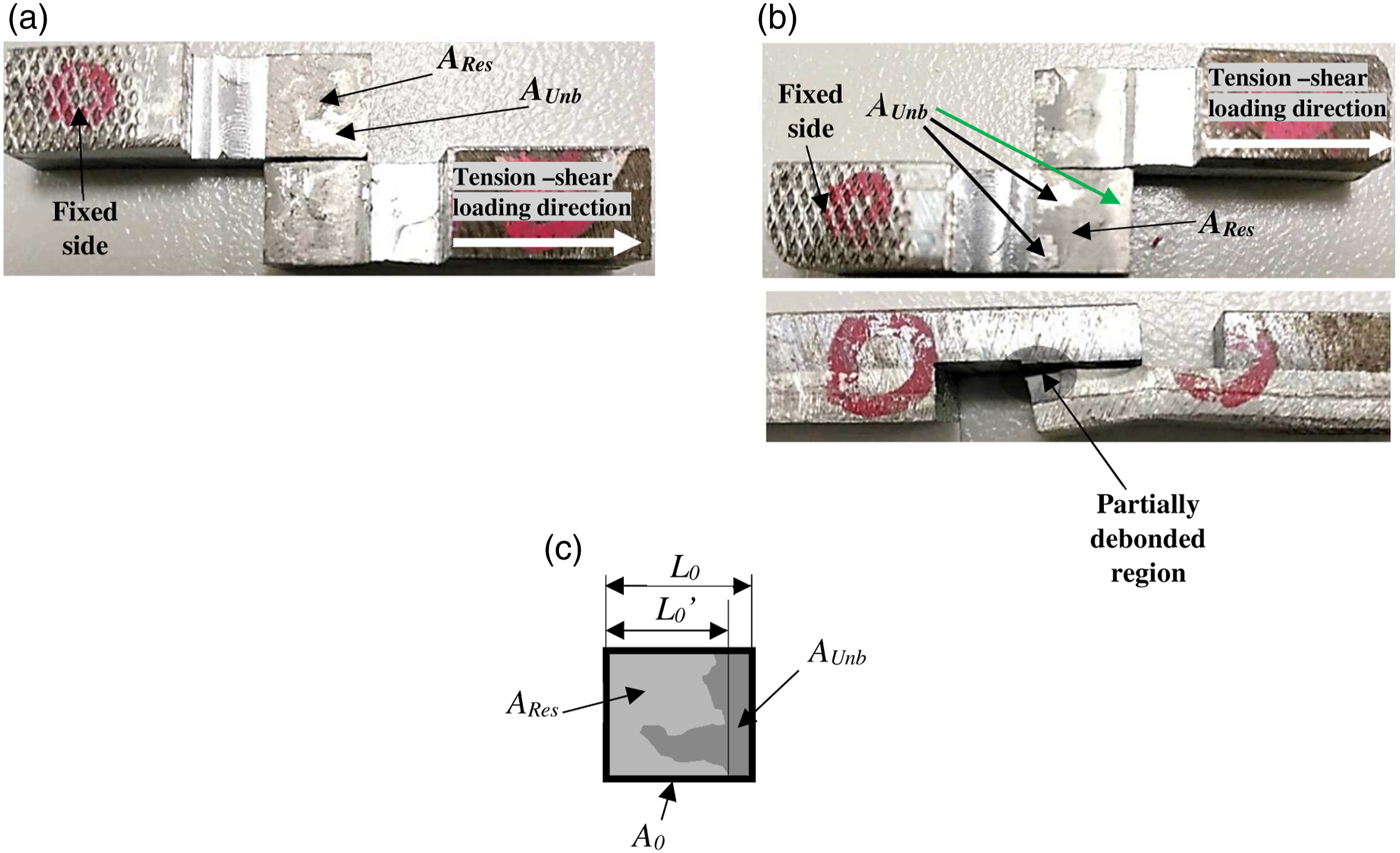
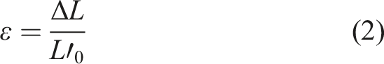
Figure 4(b) proves that weak bond regions are located where the early partial debonding had been observed during tension–shear test 2 (regions indicated with black arrows). However, at the assembly topface of the fractured surface referred by the green arrow, the signs of a partial debonding are also evident. The partial debonding at such a region had occurred but it was not detected visually throughout tension–shear test 2 until total failure of the IMBL. This is due to the fact that the available unbonded area was located in the side regions where debonding is practically impossible to be observed. Evidently, in such a side the two lips of the unbonded interfaces are sticking excessively with increasing shear loading. Identically, Figure 4(a) shows that unbonded areas are located in the region of high sticking which explains the non-detection of any partial debonding during tension–shear test 1 until total failure of the IMBL at the end of the test. Thus, the bending of Babbitt component during both tension–shear tests 1 and 2 is illustrated in Figure 3(c) and Figure 4(b), respectively. It has taken place onto the free surface of the Babbitt component due to the resistance of the IMBL material against the shear loading. Based on the findings above, the classical relationships of shear stress and strain should be slightly corrected in relation to the feature of the investigated shear testing technique so that shear resisting area will be taken into consideration instead of the apparent one. The corrected shear stress and strain relationships are given in Equation (1) and Equation (2), respectively.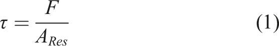
However, A Unb represents the unbonded area where early partial debonding had occurred. Such a region displays a bright and slightly smooth appearance as shown in Figure 4(b).
L 0 ’ is measured within the shear resisting area and defined in this paper as the longest distance in the direction of loading over which the shear had taken place. It should be noted that A Res and L 0 ’ have been measured within the fracture faces of the bimetallic samples 1 and 2 that the global force–displacement diagrams are reported in Figure 3(b).
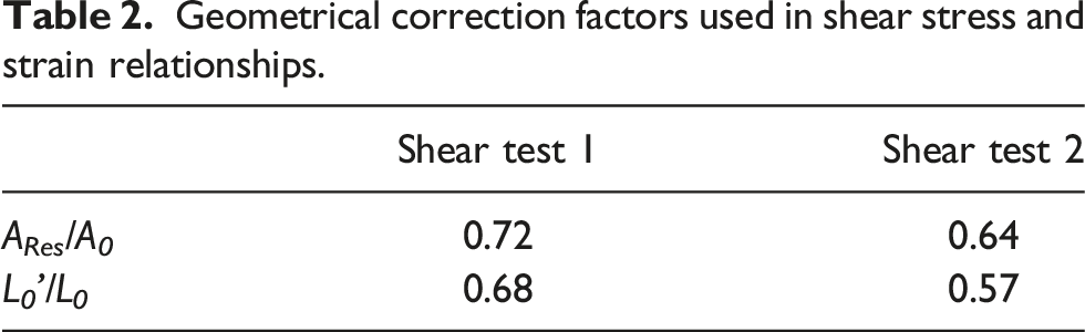
Geometrical correction factors used in shear stress and strain relationships.
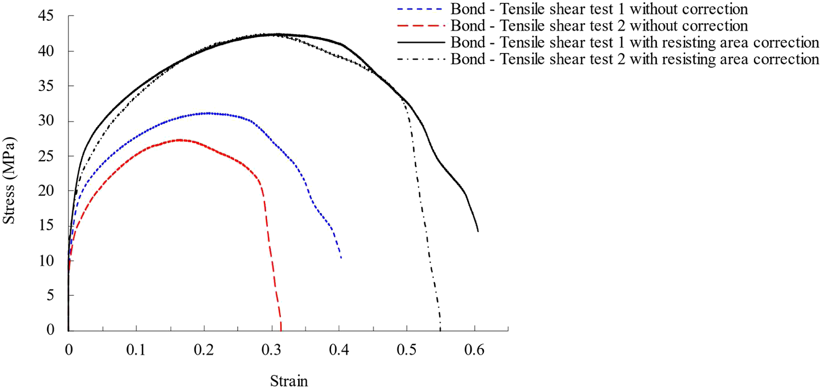
Babbitt/steel (Sn – IMCs) BL material shear stress–strain responses before and after correction for the two investigated tension–shear tests.
At the end of this section, a unified stress–strain diagram representing the appropriate mechanical behavior of the Babbitt/steel (Sn – IMCs) BL material under shear loading conditions is presented. The results presented in Figure 2 and Table 2 will be used as inputs in the designing of the bimetallic sample during the FE modeling of the tension–shear testing in order to numerically validate the shear fracture behavior of the Babbitt/steel (Sn – IMCs) BL given in Figure 5. During a numerical investigation the constitutive model parameters of the (Sn – IMCs) BL material shall be identified. The model parameters of the bond could be explored in computer simulations using the finite element method of damage during the forming of bimetallic materials for purpose of process optimization.
Figure 6 shows a sequence of SEM shear fractographs of the (Sn – IMCs) BL material at higher magnification. The SEM fractographs are taken in the resisting area (A
Res
) on the Babbitt side fracture surface. As illustrated by Figure 6(a), a damage mechanism of an obvious ductile nature was primarily the cause of tearing of the (Sn – IMCs) BL material under shear loading conditions. Indeed, ductile tearing is marked by the presence of the well-known dimpled appearance of the fracture surface. Thus, it is evident that the shape of dimple cavities is affected by local stress leaving several parabolic shapes as elongated along the shear loading direction (Figure 6(a)). Moreover, the slip bands observed at distinct locations of the fracture surface represent additional indicator of the plastic slip behavior of the Babbitt/steel (Sn – IMCs) BL material which supports the obtained stress–strain response given in Figure (5). By examining the magnified fracture surface of Figure 6(b), microdefects (micro-cavities and micro-voids) as a consequence of inclusions–matrix interfaces decohesion can be observed. These micro-cavities are detected in some stage of being coalesced constituting a third sign evidencing the higher softness of the Babbitt/steel (Sn – IMCs) BL material. The microvoids of (Figure 6(c)) observed at the interface inclusions–matrix within IMBL material are also the consequence of decohesive mechanism. The microvoids formed under shear loading in the vicinity of the inclusions–matrix interface stretch in opposite senses within the shear plan along a direction of 45° with respect to the shear loading direction. This results in developing sharp angles on each side of the microcavity (Figure 6(d)). SEM shear fractographs images obtained on Babbitt side of the Babbitt/mild steel bimetal with Sn interlayer: (a) Ductile tearing surface showing dimple cavities affected by shear loading stress, (b) Ductile tearing surface with higher magnification showing the existence of slip bands and coalescence of microvoids, (c) Decohesive mechanism at the inclusions–matrix interface, (d) Illustration of decohesive mechanism under shear loading.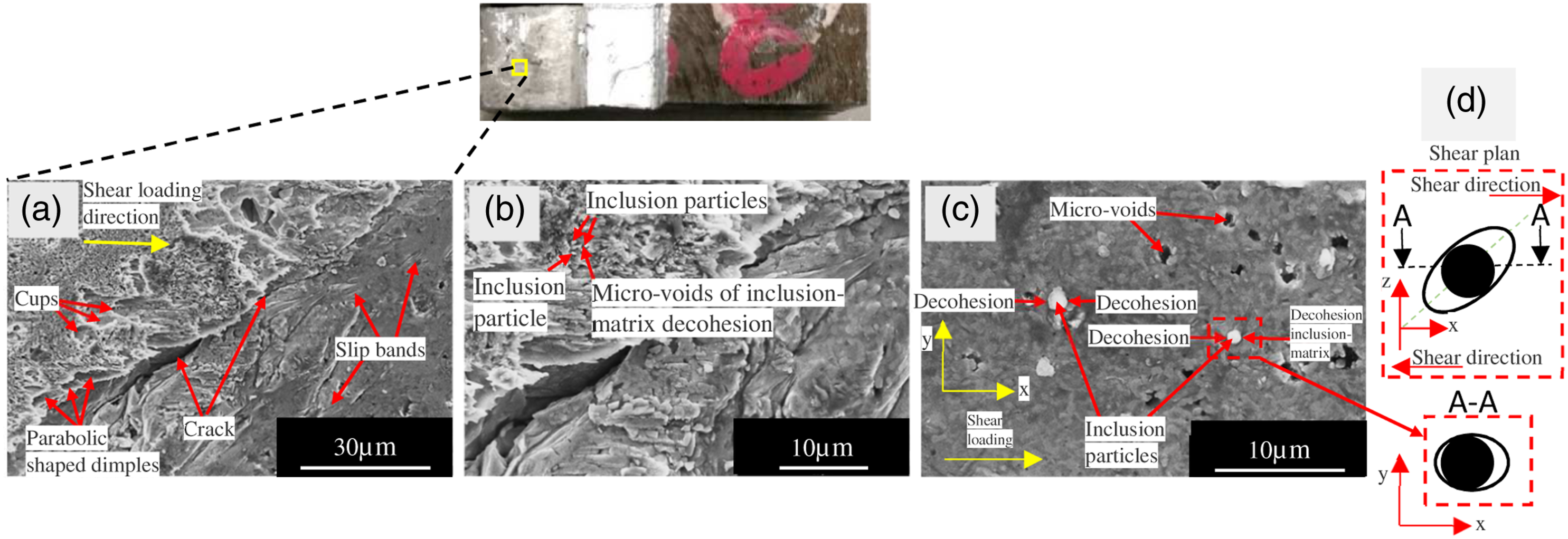
Experimental–numerical approach for the investigation of the Babbitt/steel (Sn – IMCs) BL shear fracture behavior under tension–shear testing
Elastoplastic–damage constitutive model for bimetallic composite material fracture behavior modeling
It has been demonstrated from Figure 3(b) that the Babbitt/steel (Sn – IMCs) BL material exhibits a plastic slip behavior under shear loading with good ductility rather than a brittle behavior. This implies that the mechanism of damage responsible of the (Sn – IMCs) BL failure and bimetal total debonding was ductile in nature that was also supported by the sequence of the SEM fractographs of Figure (6). Hence, the constitutive laws used to describe the bond material behavior require the consideration of the ductile damage evolution on the elastoplastic constitutive relations. In this paper, the damage dependent constitutive equations describing the constitutive behavior with ductile damage effect of the different constituents of the Babbitt alloy/mild steel bimetal including the (Sn – IMCs) BL are written within the thermodynamic of irreversible processes theory. Thus, the concept of internal state variables and continuum damage mechanics (CDM) framework are considered. We confine ourselves in the present work to exploit a such material behavior modeling in FE simulation of the tension–shear testing to characterize the constitutive behavior and fracture of the (Sn – IMCs) BL material created at the interface of bimetallic specimen. The employed constitutive modeling is explained deeply in previous works 21 where the anisotropic aspect of ductile damage has been investigated and damage state has been defined using a second rank symmetric tensor.
In the present study, the assumption of the isotropy of ductile cavitation is considered. Hence, an isotropic version of the constitutive model of Rajhi et al. 21 will be employed in the current study where the damage state is described by one scalar variable D. The ductile damage modeling has been widely investigated through two considerably dissimilar approaches: the first one is physically motivated and based on the study of germination, growth and coalescence of an elliptical or spherical cavities in an elastic–plastic matrix. 22 However, the second one (phenomenological in nature) is relying on the continuum damage mechanics (CDM) theory 23 wherein the damage is measured through its effect on mechanical behavior in an indirect way.
Here, the constitutive equations of the employed elasto-plastic damage model will not be presented. The readers are referred to the references23,24 for further details in the case of ductile damage. The constitutive model is written within a non–associative plasticity theory, where the von Mises (equivalent) stress norm is used to describe the isotropic plastic flow accounting for both kinematic and isotropic hardening with the assumption of the isotropy effect of the ductile damage D. The employed isotropic damage model includes the same number of material parameters of the anisotropic damage model of Rajhi et al.
21
Accordingly, the material parameters involved are two elastic parameters: E and ν, five plastic parameters to describe the isotropic plastic flow: σ
y
, Q, C, b, a, which are the yield stress, the moduli and the non-linearity parameters of an isotropic and kinematic hardening, respectively. However, the damage evolution relation proposed by Lemaitre
25
and applied by several authors for ductile fracture prediction in metal forming simulation24,26,27 is implemented in the employed elasto-plastic damage model and writes as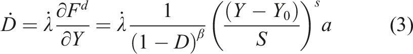
Furthermore, to describe the elasto–plastic behavior of the material in a virgin state, the damage variable D is overlooked by the model thanks to a flag parameter so that the simulated component remains intact throughout the entire FE analysis. In such a case, non–coupled to damage (NCD) elasto–plastic calculations could be conducted requiring only the set of parameters (E, ν, σ
y
, Q, b, C, and a). However, to describe the damaged mechanical behavior of the material, the set of material parameters (E, ν, σ
y
, Q, b, C, a, S, s, β and Y
0
) is used to perform elasto–plastic calculations coupled to damage (CD). In such a case, as soon as the condition
It is also noteworthy that even if (Y
0
= 0), when the condition
Design of tension–shear bimetallic sample
The numerical simulation of bimetal tension–shear testing involves the design and FE modeling of the Babbitt alloy/mild steel bimetallic composite sample that the geometry is shown in Figure 1(c). Accordingly, the sample is sliced into several sections, as shown in Figure 7, so that specific mechanical properties and characteristics are assigned to each section. The thin (Sn – IMCs) BL can be defined by means of a section with very thin thickness. Hence, the simulated bimetallic sample is modeled as a sandwich–like arrangement of the Babbitt alloy and mild steel with a thin IMBL interface as observed by SEM microscopy (see Figure 2). Furthermore, the IMBL is fragmented into three isolated sections as the bond portions located underneath the milling–grooves have been removed during the manufacturing of tension–shear specimen. The IMBL portion located in the middle of the bimetallic specimen is subjected to larger amount of shear loading. Therefore, according to discussion in paragraph (II-3) related to oxidized area and early partial debonding phenomenon it may be modeled in two ways. Either only the shear resisting volume of the IMBL is added between the Babbitt alloy and mild steel and spread over the shear resisting area (see Table 2 for length and area repartition proportions). In this case, the volume of unbonded zone in reliance on fracture surface macro-observation is left empty. Or the IMBL portion located in the middle of the bimetallic sample is sliced into two principal parts. A first part defined by the section resisting to shear loading to which will be assigned the real IMBL mechanical characteristics. Whereas the second section within which oxidized or unbonded area is intended to occur is considered as a weak region to which is assigned the mechanical behavior of a fictive brittle material of the IMBL. Consequently, brittle volume to which is assigned the virtual brittle behavior will be damaged too early. In such a case, the resisting area formed only by the actual (Sn – IMCs) BL ductile material continues to undergo the shear loading until total failure and debonding of the bimetallic sample (for this instance see also Table 2 for length and area repartition proportions). Design of Babbitt/mild steel tension–shear bimetallic specimen for FE modeling of tension–shear testing.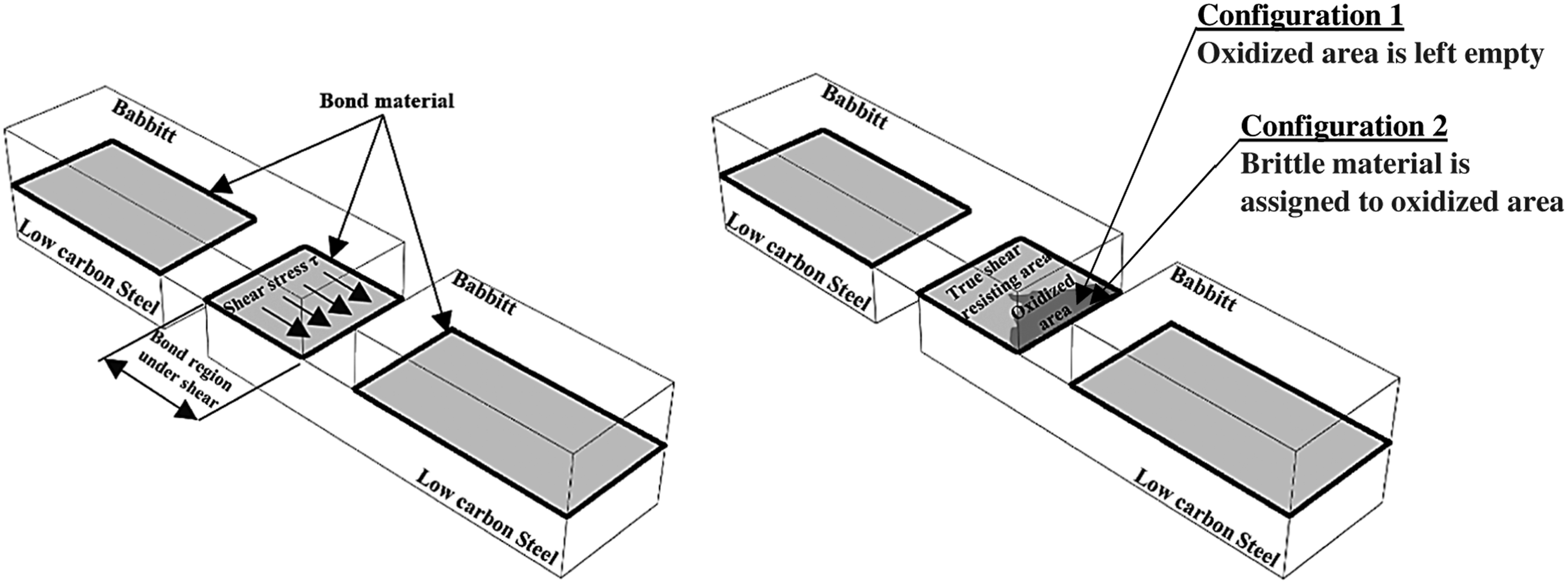
The FE modeling of tension–shear testing according to the two suggested configurations has been established and checked. It has been found that when the second assumption is considered, break in slope of the elastic modulus has been detected in the computed solution which leads to a slight shift on the entire global force–displacement diagram. However, no break in slope of the elastic behavior and beyond had been observed over the experimental force–displacement diagram (see Figure 1(c)). This leads to the idea that a partial debonding within the oxidized area identified for the investigated tension–shear samples starts early enough in a manner that its effect did not appear onto force–displacement diagram. Hence, the process of partial debonding could be modeled either based on the first configuration or considering the second one while increasing brittleness of IMBL virtual material assigned to the oxidized area. The latest second configuration has been implemented and checked. It was noted that the increase of the fragility of the bond material at oxidized area by disabling hardening and accelerating damage occurrence and evolution produces the early partial debonding by fast cracking of brittle material over the oxidized area. This leads also to disappearance of elastic modulus slope change.
Even though second configuration seems to be more realistic, we suggest in the present study, the FE modeling of the tension–shear testing by implementing the first method where the oxidized volume is left empty for reasons which will be unveiled elsewhere.
Identification of constitutive model parameters of the Babbitt/steel (Sn – IMCs) BL material
The mechanical behavior of the material at the interface has been characterized experimentally during tension–shear testing in section (II-3). Accordingly, a unified shear stress–strain curve has been provided for the (Sn – IMCs) BL material while considering some modifications of geometrical nature on the stress and strain relationships. Hereafter, the unknown mechanical behavior of the (Sn – IMCs) BL material will be predicted in a different way by numerical simulation. However, the experimental results and observations presented in section (II) remain essential as they are employed to build the FE model of tension–shear testing. The proposed FE model of tension–shear testing includes together the design of tension–shear sample according to the outcomes of section (III-2) and the definition of the elastoplastic–damage behavior of each material constituting the bimetallic specimen. This requires the implementation of the constitutive model presented in section (III-1).
Hereafter, we suggest solving the problem of unknown mechanical behavior of the (Sn – IMCs) BL material under tension–shear testing by following the steps described in diagram of Figure 8. The methodology is based on the combination of experiment and numerical simulations using ABAQUS/Explicit® FE code with the specially developed VUMAT subroutine. According to the diagram illustrated in Figure 8, a set of three numerical simulations including simple tension and tensile–shear tests are required to successfully identify the mechanical behavior of the Babbitt/steel (Sn – IMCs) BL material. The experimental results coming only from tension–shear test 1 are exploited as input for the FE model of tension–shear testing. They will be used either in the step of design of tension–shear sample by applying the geometrical correction coefficients reported in Table 2 or during the identification process of bond model parameters as per diagram of the global force–displacement given in Figure 3(b). Identification strategy diagram of the shear fracture constitutive model parameters for the Babbitt/steel (Sn – IMCs) BL material.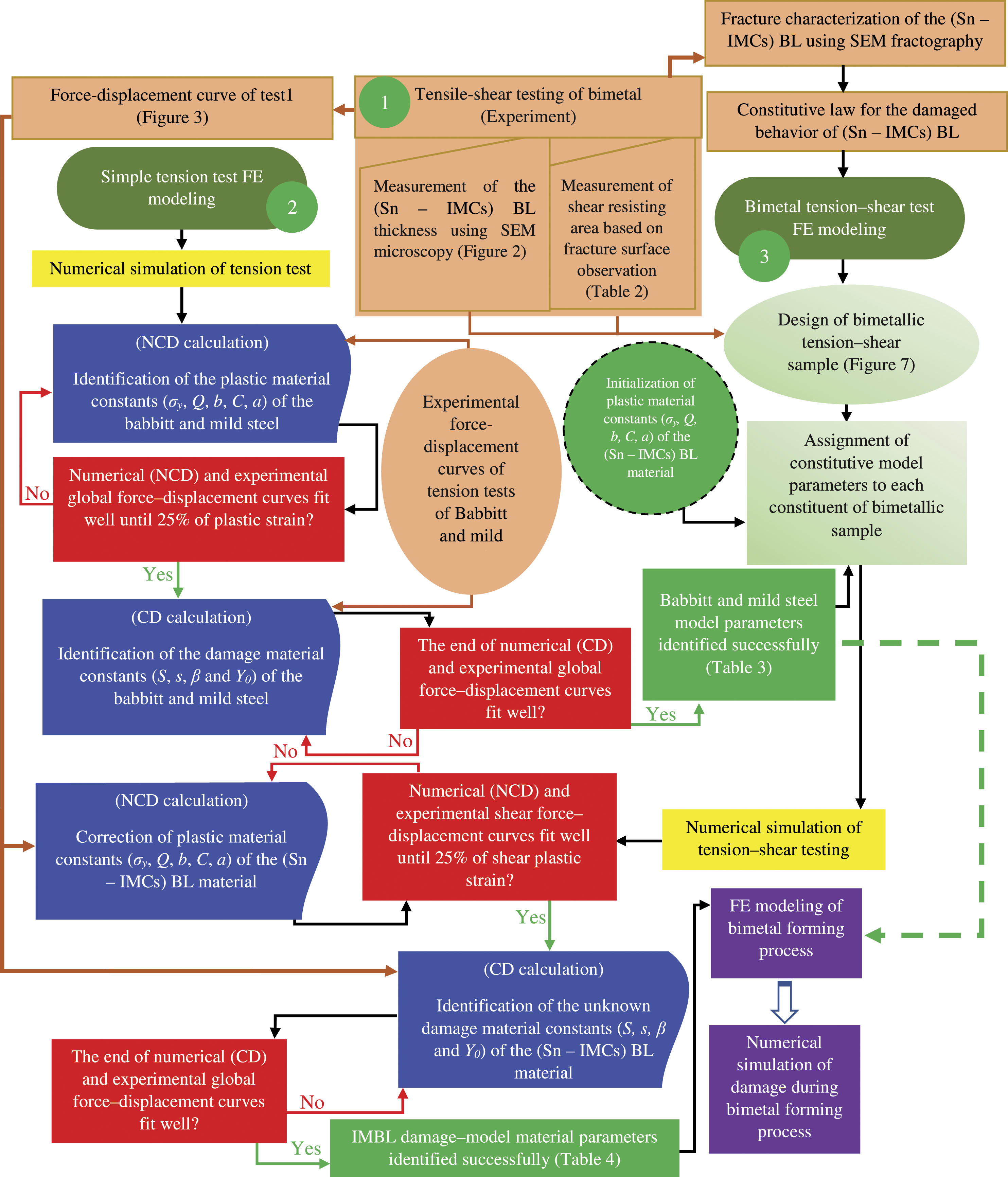
Simple tension test of cast and substrate components of the bimetallic composite sample: experiment and FE modeling
As shown in diagram of Figure 8, both experiment and FE modeling of simple tension test for the Babbitt metal and mild steel are needed in the identification process of the damage constitutive model parameters of the (Sn – IMCs) BL material. Accordingly, tension test samples (16*4*3.3 mm3) of Babbitt metal and mild steel are manufactured on a typical vertical milling center and loaded in tension at constant cross–head displacement rate of 2 mm/min by means of the tension test machine used in section (II-3). The obtained global force–displacement diagrams are employed in the identification of the model parameters (σ y , Q, b, C, a, S, s, β, Y 0 ) for these materials. The identification of model parameters for Babbitt metal and mild steel constituting the bi–metal specimen sections is indispensable for the identification process of the fracture behavior of (Sn – IMCs) BL material as shown in Figure 8. The identification procedure of behavior parameters of the Babbitt metal and mild steel is based on numerical simulation of simple tension tests. As shown in Figure 8, the material parameters identification strategy is accomplished through two main consecutive steps. An uncoupled to damage analysis (NCD) followed by a coupled to damage analysis (CD) should be performed. First, the material constants (Q, b, C, a) are identified by using the experimental global force–displacement curves portion before 25% of plastic strain while neutralizing the damage effect (NCD). Then, the remaining experimental curves going to the final rupture are employed to calibrate the damage parameters (S, s, β, Y 0 ) and to regulate the hardening parameters which rely on the fully coupled analysis (CD). It should be noted that the developed VUMAT subroutine includes a flag parameter (FPD) allowing to conduct an uncoupled to damage analysis (NCD) when FPD = 0 and a fully coupled analysis (CD) when FPD = 1.
Elastic, plastic, and damage parameters for the Babbitt alloy and mild steel.
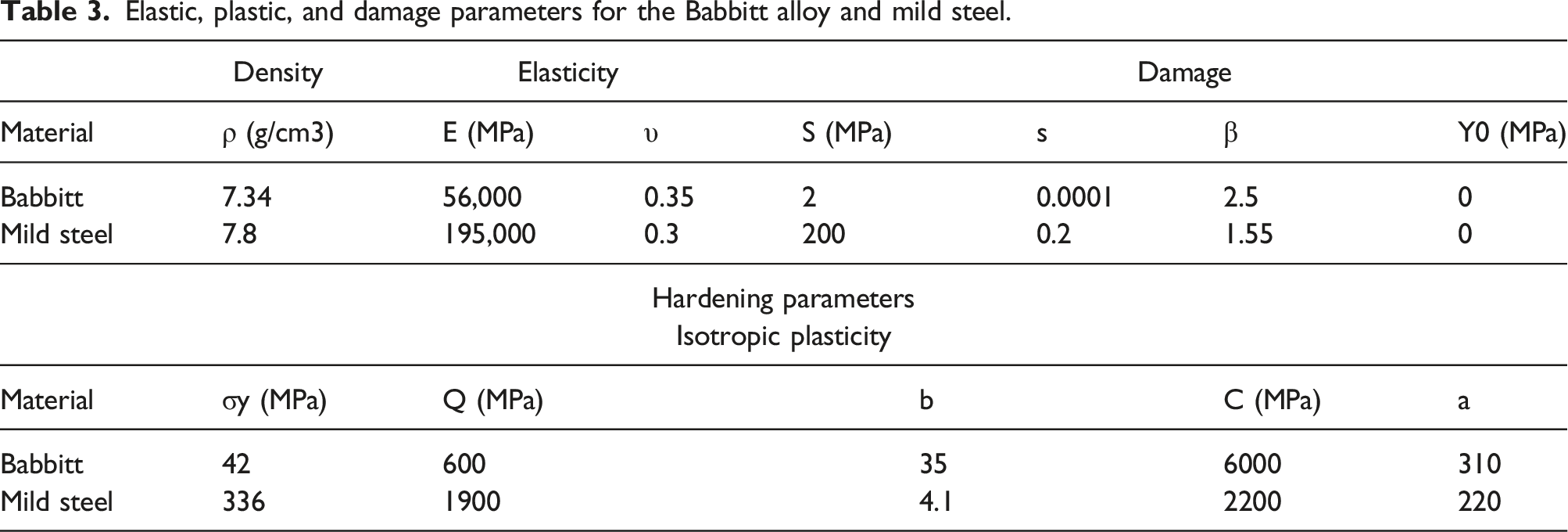
In the case of mild steel, the end of experimental post–peak failure stage was correctly forecasted by current damage model as shown in Figure 9(a) which was not easy to reproduce in the case of Babbitt metal (Figure 9(b)). Thereby, a further investigation including mesh sensitivity analysis with its effect on damage parameter β was performed during the numerical simulation of tension test of Babbitt to find the best fit between the end of experimental curve and numerical solution. Indeed, the constitutive equations of the present model are written within a local formulation, hence, the coupled to damage (CD) numerical solution is influenced by the meshing element type, orientation and size. The parameter η given in Figure 9(b) represents the meshing element size. Several simulations coupled to damage (CD) were performed using different combinations of damage material parameter β and meshing size η to obtain the computed force–displacement curves which are presented in Figure 9(b). Among the numerically predicted solutions illustrated in Figure 9(b), the red solution arising from the application of combination (β = 2.5, η = 0.2 mm) is considered the most appropriate. This combination will be retained hereafter together with the other model parameters reported in Table 3 to describe the damaged elastoplastic behavior of the Babbitt metal during tension–shear testing simulation. Experimental, numerical uncoupled, and fully coupled force–displacement curves for: (a) mild steel and (b) Babbitt alloy.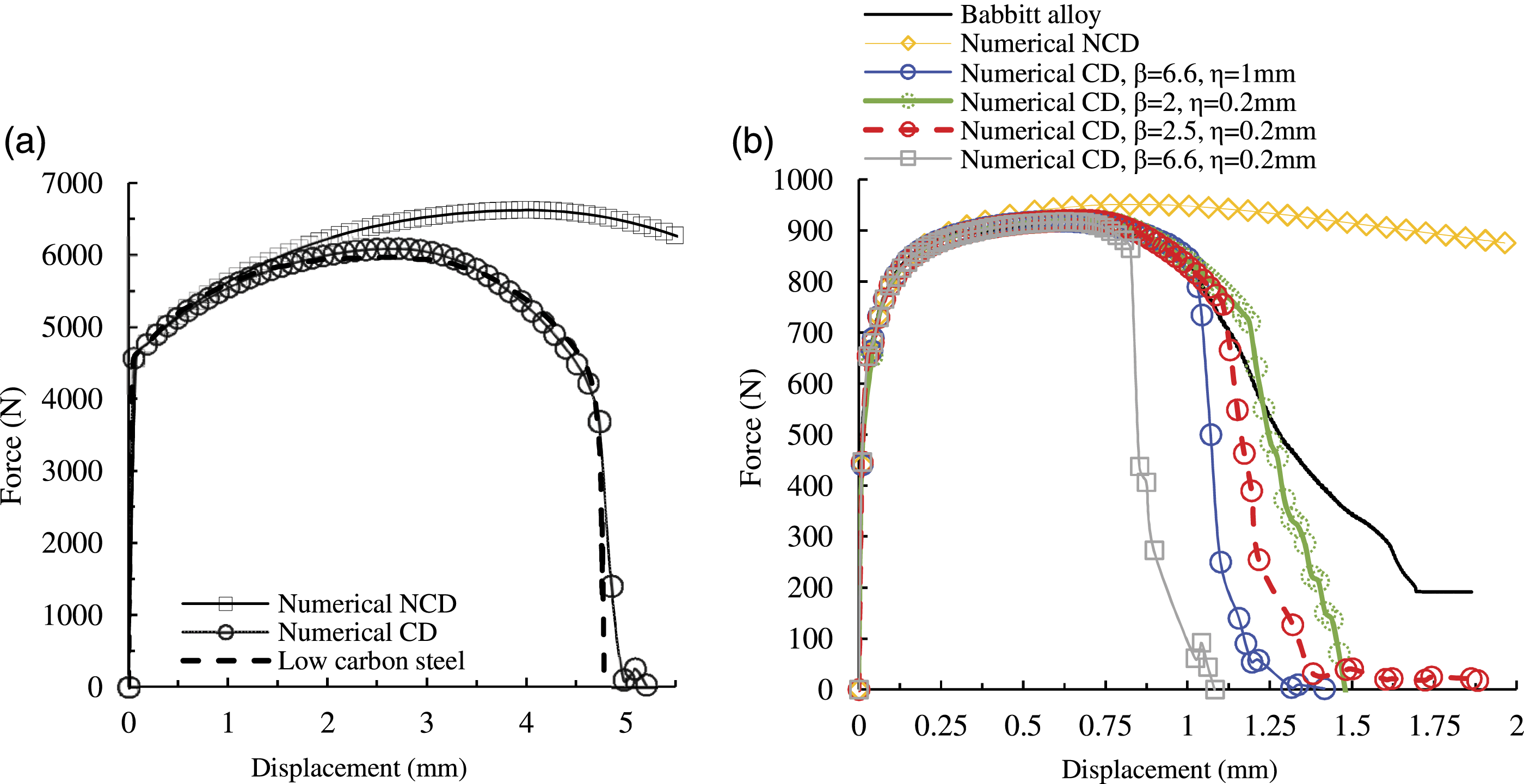
FE modeling of bimetallic composite sample tension–shear testing
The aim of this section is the numerical simulation of tension–shear test presented in Figure 3. As illustrated by the diagram of Figure 8, the obtained behavior parameters for the Babbit and mild steel reported in Table 3 serve as inputs for FE model of bimetal tension–shear test and used in identification process of the (Sn – IMCs) BL material parameters. The unknown shear fracture behavior of the Babbitt/steel (Sn – IMCs) BL material can be identified by conducting tension–shear testing simulations while altering the (Sn – IMCs) BL model material parameters until the numerical and experimental force–displacement curves fit well. As shown in Figure 8, the identification procedure of the (Sn – IMCs) BL material constants should be conducted in a manner similar to that adopted with Babbitt alloy and mild steel in tension testing. Uncoupled to damage analysis (NCD) is carried out to determine the plastic parameters of the (Sn – IMCs) BL material followed by coupled to damage analysis (CDs) to find the damage parameters. It is noteworthy that both the (Sn – IMCs) BL thickness and resisting shear area measurements given in Figure 2 and Table 2, respectively, are essential inputs for designing of bimetallic tension–shear specimen (Figure 8). We need to keep in mind that the measurements arising from tension–shear testing 1 are considered. Accordingly, among the geometrical correction coefficients reported in Table 2, those occurring as a result of tension–shear testing 1 are applied to the configuration 1 of Figure 7 during the design and FE modeling of bimetallic tension–shear sample. In addition, global force–displacement experimental data arising from the same test (see Figure 3(b)) are used during calibrating process of the (Sn – IMCs) BL material constants.
The specimen geometry given in Figure 1 is employed in FE simulation of tension–shear testing. The Babbitt alloy and mild steel sections constituting tension–shear specimen are meshed employing 3D hexahedral tri-linear solid elements (C3D8R). Mesh refinement is performed within the Babbitt alloy and mild steel zones located in the vicinity of the IMBL by keeping the smallest average size of meshing used during identification process (0.2 mm) for these two materials. The intermetallic region where the (Sn – IMCs) BL is placed is meshed using the same element type with mesh smallest mean size of about 5 μm, i.e., the thickness of the (Sn – IMCs) BL (see Figure 2). The boundary conditions used in tension–shear test FE modeling and the 3D mesh of the tension–shear sample are shown in Figure 10. The boundary conditions applied to tension–shear test FE model illustrated in Figure 10 are similar to the simple tension test simulation, i.e., fixing the sample to a rigid fixture frame on one side and pulling the other side. Recalling that to adhere experimental test feature (Figure 3(a)), pulling is applied to the bimetallic specimen side where longest portion of the Babbitt metal is placed with a constant linear velocity V of 1 mm. min−1. The fixture was modeled as a rigid part and meshed using R3D4 elements: A 4-node 3-D bilinear rigid quadrilateral available in ABAQUS/Explicit® FE software. Whereas the different sections of bimetallic sample were assumed to respond elasto–plastically before fracturing in a ductile manner accounting for the identified behavior parameters for the Babbitt alloy and mild steel reported in Table 3. Tension–shear testing boundary conditions and 3D mesh of the tension–shear specimen.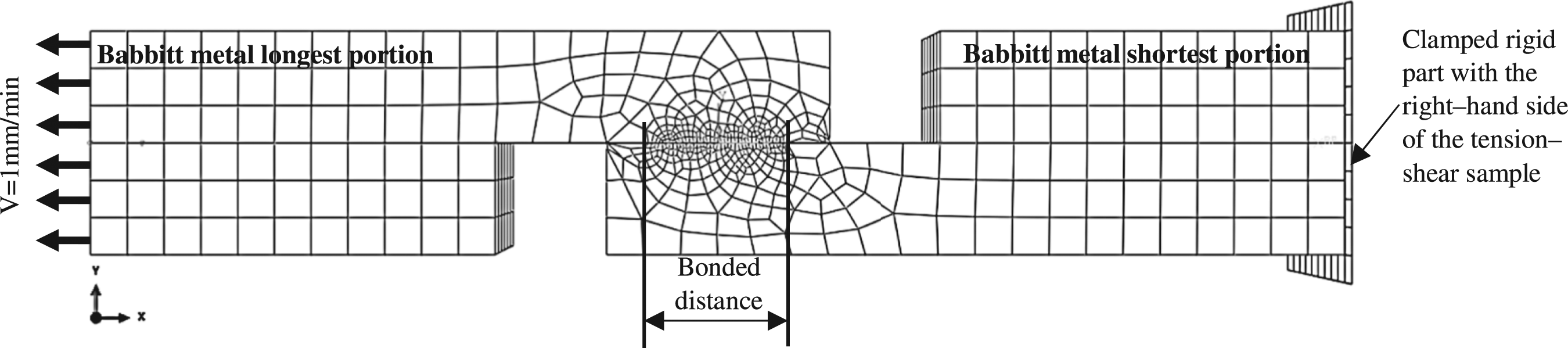
It also recalled that in section (III-2) two configurations are suggested to model the bimetallic sample. As mentioned above, the first configuration is defined by removing the volume of bond where the occurrence of unbonded region and early debonding are intended. Herein, the FE modeling of tension–shear testing by implementing of the first configuration is chosen. The main reason for this choice is that the FE model of second method involves more meshing elements which leads to a considerable increase in CPU–time of about 29% making the identification process cumbersome.
Elastic, plastic, and damage parameters of the Babbitt/steel (Sn – IMCs) BL material.

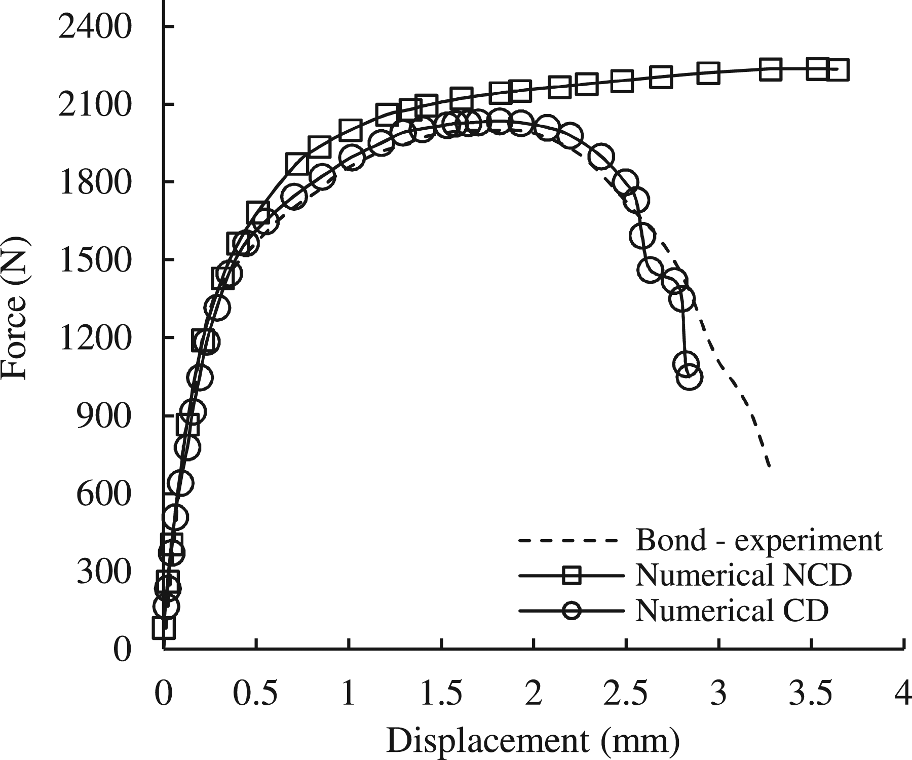
Experimental, numerical uncoupled, and fully coupled force–displacement curves of the Babbitt/steel (Sn – IMCs) BL material.
The mapping of displacement, von Mises equivalent stress and ductile damage obtained at different magnitudes of displacement during numerical simulation of tension shear testing are shown in Figure 12. The results presented in Figure 12 are achieved by applying the identified material parameters of Babbitt alloy, mild steel and (Sn – IMCs) BL material reported in Tables 3 and 4, respectively, to the constitutive model through a fully coupled to damage (CD) analysis. The results of Figure 12 could be correlated with the global force–displacement diagram of (Sn – IMCs) BL material plotted in Figure 11 via the displacement magnitude. Such a match is useful to get an idea of how the bimetallic sample is deformed as well as the state of damage in the bond throughout the tensile-shear tests. Note that in shown mapping of the ductile damage, the damage magnitude is defined by the subroutine VUMAT output SDV21. Mappings of displacement magnitude, VOM equivalent stress and damage within bimetallic sample at different magnitudes of displacement during tension–shear testing: (a) 1.76 mm, (b) 2.38 and (c) 2.84 mm (c: with removing fully damaged elements).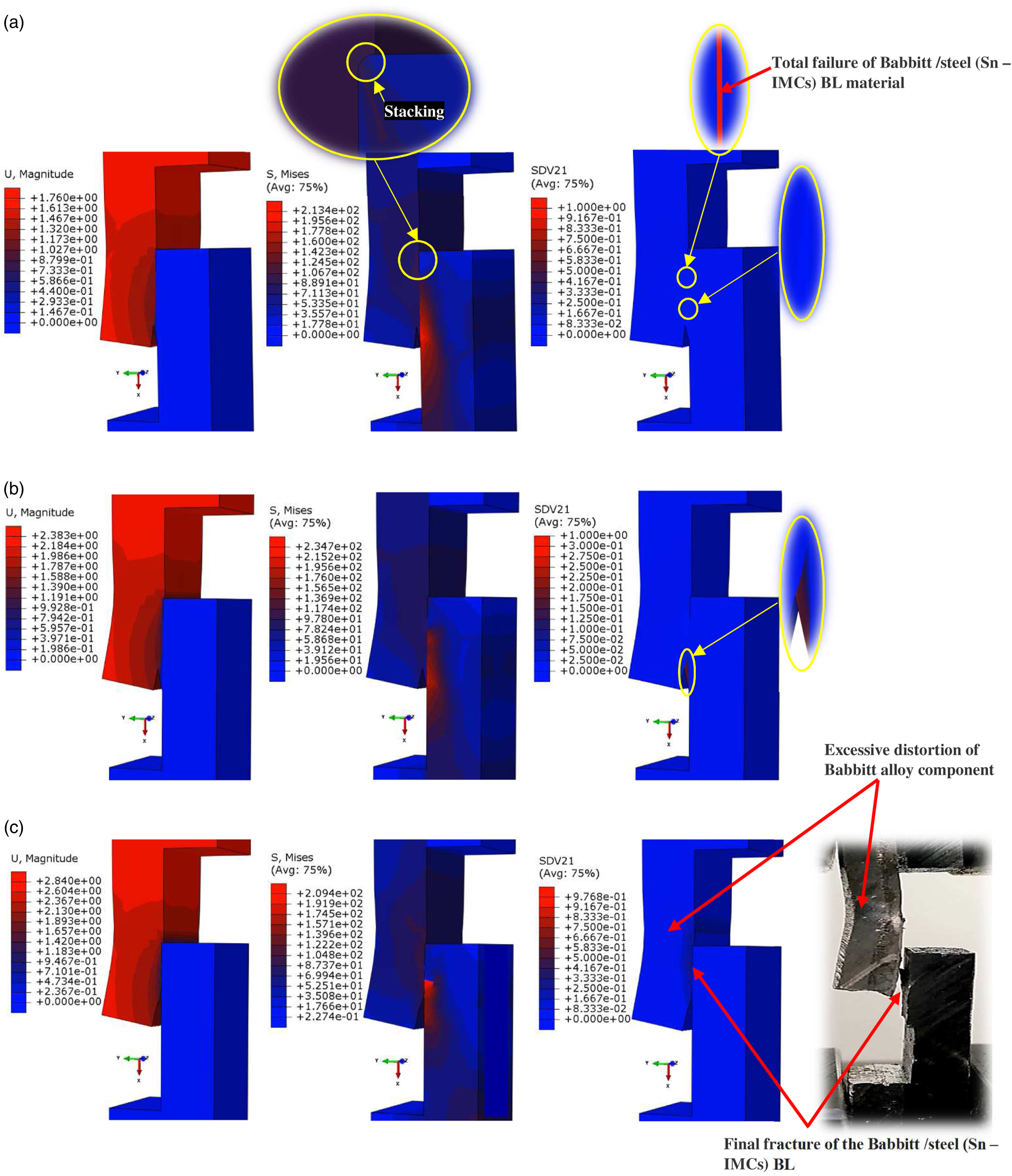
From Figure 12, it clearly appears that bimetallic specimen under tension–shear loading has been correctly simulated on the basis of the present damage model. Figure 12 shows how the model predicts satisfactorily the distortion of bimetallic specimen. Such an important deformation is manifested by the increasingly bending of the free surface of the Babbitt alloy component due to a strong resistance of (Sn – IMCs) BL against shear loading before total fracture. The mapping of VOM stress shows that the maximum stress located within two principal regions of the simulated bimetallic sample. First, equivalent VOM stress concentrates within the Babbitt component where stacking of Babbitt over the mild steel takes place. Also, stress emphasis within an obvious extended region of mild steel due to resistance of a portion of adhered (Sn – IMCs) BL against shear loading. Such a portion of bond is the one that has not undergone the stacking process (Figure 12(a)). Subsequently, the region of the mild steel component where the maximum stress was concentrated has been observed to shrink with increasing shear loading. This is because the (Sn – IMCs) BL regions excessively affected by damage widens and give up with increasing displacement (look at the mappings of VOM stress within steel and compare them over the Figure 12(a)–(c)). Another feature is noteworthy. A close look of damage mapping of Figure 12(a) shows that crack had initiated inside the simulated (Sn – IMCs) BL in the vicinity of stacking region as some meshing elements of the bond have been fully damaged in that zone. However, on the bottom side of the bonded region the damage within the (Sn – IMCs) BL remains low without exceeding 3%. By increasing the magnitude of displacement, damage within the bottom side of the bonded region grows slowly and reaches 23% touching further elements of that zone as shown in damage mapping of Figure 12(b). The discussion above could be evidenced by Figure 13 where the evolution of damage within some selected elements of stacking region (elements 342 and 337) and inside bottom region of the simulated (Sn – IMCs) BL (element 385) are plotted with respect to the displacement magnitude. Numerically predicted damage evolution within the upper side (elements 337 and 342) and bottom side (element 385) regions of the simulated (Sn – IMCs) BL plotted versus displacement magnitude through tension–shear testing.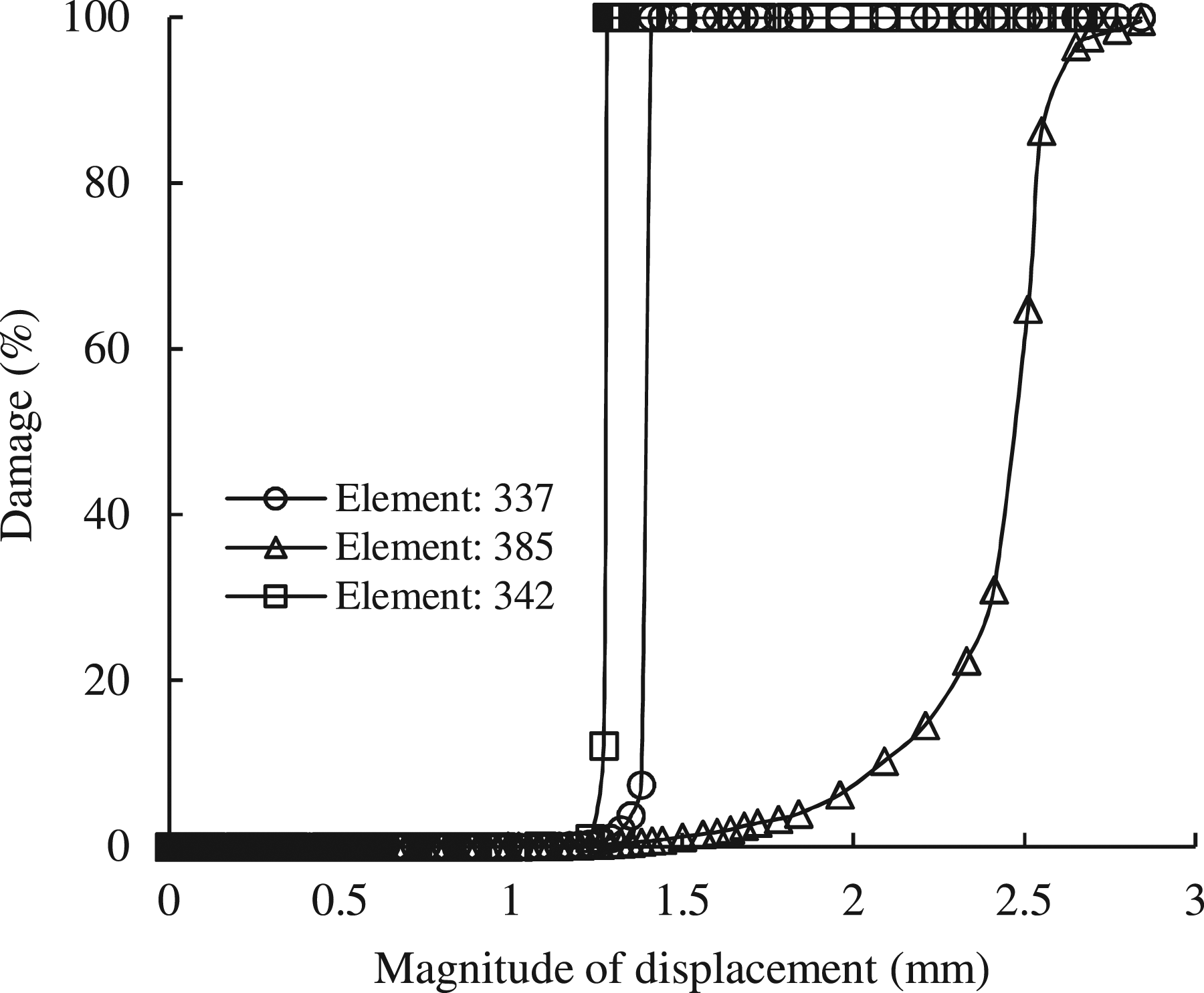
Figure 12(c) illustrates the mapping of the different mechanical fields at total fracture of bimetallic sample by almost complete failure of the simulated (Sn – IMCs) BL which occurs at a displacement magnitude of 2.84 mm. It should be noted that to visualize the total debonding of simulated bimetallic specimen at the end of tension–shear simulation, the mesh elements within which the damage reaches damage threshold value (D c = 0.98) should be completely removed from the meshing (see legend of damage mapping of Figure 12(c)).
So far, the mechanical behavior of the (Sn – IMCs) BL material has been identified experimentally. However, the aim of the present section is to determine the mechanical behavior of the (Sn – IMCs) BL material under shear testing by numerical simulation according to the strategy defined in diagram shown in Figure 8. To evaluate the ability of the constitutive model and the proposed numerical methodology, shear fracture behavior of some fully damaged meshing elements of the simulated (Sn – IMCs) BL material has been investigated. The fully damaged meshing elements were selected together from the bottom of the bonded region (elements: 385–390) and from the highly deformed region where stacking process occurred (elements: 331, 336, 337) (see Figure 14(a)). (a) Distribution of shear stress component S
12
within bimetallic sample at a displacement magnitude of 0.85 mm with illustration of both the shear-deformed elements (385–390) of the bottom region of the simulated (Sn – IMCs) BL and the elements (331, 336, 337) of bond stacking zone, (b) Numerically predicted shear stress S
12
–shear displacement curves for elements sets (385–390) and (331, 336, 337) of the simulated (Sn – IMCs) BL compared with experiment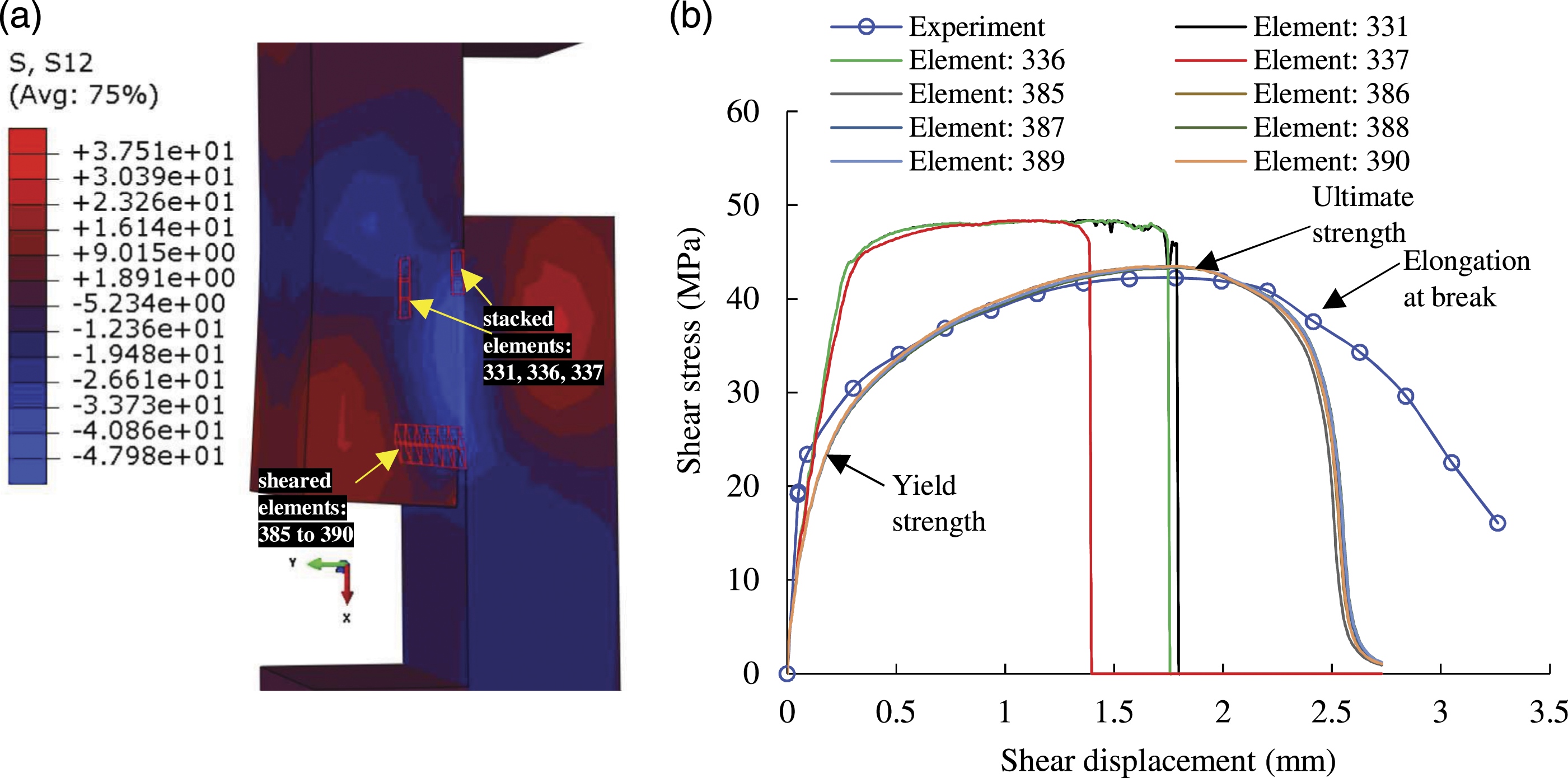
The evolution of shear stress component S 12 within these elements with respect to the global shear displacement is plotted in Figure 14(b) and compared to shear stress (corrected one)–shear displacement diagram of the (Sn – IMCs) BL arising from test 1. The results obtained from such comparison could be judged very satisfactory (see Figure 14(b)). It can be shown from Figure 14(b) that shear fracture behavior of the IMBL is predicted by FE simulation with a good average error namely: 1.05%, 0.97% and 0.96% for the yield strength, ultimate strength, and elongation at break, respectively. Unlike the meshing elements set (331, 336, 337) located inside the stacking zone of the simulated (Sn – IMCs) BL, shear fracture behavior within the elements set (385–390) of the bottom region of the bond is deemed comparable to the experiment. Indeed, the elements sets (331, 336, 337) and (385–390) of the simulated (Sn – IMCs) BL have not undergone the same local stress state during tension–shear testing. The external applied tension loading transforms to a complex local stress state manifested by excessive stacking of the elements (331, 336, 337) of the simulated (Sn – IMCs) BL as they were crushed between the Babbitt and mild steel parts with increasing shear loading. This results in a significant increase in the work hardening of the (Sn – IMCs) BL material within the stacking region. The latter undergoes an early total failure compared to the region located at the bottom of the assembly, in quite accordance with the results presented in Figure 13.
Conclusion
In this paper, a combined experimental and numerical strategy to study the shear fracture behavior of the intermetallic bond layer (IMBL) of the Babbitt/mild steel bimetallic bearing material has been presented. The macro stress–strain behavior of the bond in the tensile-shear tests was evaluated by considering the local shear surface geometry instead of the apparent bonding zone. Fractographic examination was performed to identify damage mechanism responsible for (Sn – IMCs) BL fracture under shear loading. Observations made using SEM reveal typical signs of ductile tearing of the intermetallic bonding layer (IMBL) under shear loading. Based on experimental observations, a FE constitutive damage model for the Babbitt/steel (Sn – IMCs) BL is proposed. Numerical simulation of tension–shear tests were performed using VUMAT platform of ABAQUS/Explicit® FE code. The identification of the constitutive model parameters for the IMBL material was based on correspondence between computed and experimental global shear force–displacement responses. The FE simulation results achieved within the sheared region of bimetallic sample have been shown to be reliable by comparison to the experimental values. They predict the shear fracture behavior of the IMBL with an excellent average error margin namely: 1.05, 0.97 and 0.96% for the yield strength, ultimate strength, and elongation at break, respectively. The constitutive parameters of the IMBL resulting from current study can be used to predict damage and fracture of the bimetallic composites during forming process.
Footnotes
Declaration of Conflicting Interests
The author(s) declared no potential conflicts of interest with respect to the research, authorship, and/or publication of this article.
Funding
The author(s) disclosed receipt of the following financial support for the research, authorship, and/or publication of this article: “This research has been funded by Scientific Research Deanship at University of Ha’il – Saudi Arabia through project number RG-21092”.
Data availability statement
The data that support the findings of this study are available from the corresponding author upon reasonable request.