
Abstract
Glass fiber reinforced polypropylene (GF-PP) composites have proven a great potential in the designation and manufacturing of control arms, leaf springs, barriers, beams and bridge decks. Two-pass injection molding of GF-PP was investigated in this study. Polypropylene (PP) was injected with different weight fractions (w%) of chopped glass fibers (GFs) with different fiber feedstock lengths (FFSLs). The composites were then crushed and re-injected once again. Some specimens were burned out to check the actual weight fractions and fiber lengths after the injection processes. The fiber lengths dramatically decreased due to damages during two-pass injection processes and crushing. The manufactured specimens were tested in tension, and the results indicated that the tensile strength increased slightly at w = 10% of GF. Further increase of GF weight fraction leads to a drop in the tensile strength below neat PP. The results of SEM micrographs showed an increase in air voids concentrations at high GF percentages which clarifies the reason behind the drop in the tensile strength. Also, in-plane shear tests were carried out using the Iosipescu fixture where a slight increase in the in-plane shear strength was noticed by increasing fiber weight fractions. In-plane shear moduli of all specimens were measured experimentally by strain gauges and calculated theoretically. The shear modulus was enhanced by glass fiber addition and a further increase was noticed by increasing the fiber weight fractions.
Keywords
Introduction
Polymers have become indispensable in modern life as they are used in a variety of applications in place of metals owing to their low densities, good corrosion resistance, and low electrical and thermal conductivity. Thermoplastics are the most important plastics commercially where they represent around 70% of the tonnage of all synthetic polymers produced worldwide. 1 This importance appears in their recyclability and relatively cost-competitive compared to other types of polymers for most thermoplastics. Polypropylene (PP), which is one of the lightest thermoplastics, can be subjected to a high number of flexing cycles without failure and its strength-to-weight ratio is high.2,3 PP is an ideal material for the injection molding process. Also, there are other processing techniques applied for PP including blow molding, compression molding, rotational molding, extrusion blow molding, injection blow molding, and injection stretch blow molding. PP could be produced using the 3D Printing process and it is suitable for complex models, prototypes, small series of components, and functional models. PP applications are extremely huge including injection molded parts for automotive, houseware and medical-ware, fiber products for carpeting and electric goods.
In order to enhance the mechanical properties of the polymers, they may be reinforced using different types of fibers, where GF are the most commonly used fibers for this purpose. In the area of civil engineering, GF-PP looks to offer good potential for usage in the construction of prefabricated buildings like barriers, beams, and bridge decks. 4 In a comparison of regularly used seat designs, the robust bus seat created by Vaidya and Chawla 5 offers weight and overall production cost savings of 43% and 18%, respectively. The design of the leaf spring was proven to work well with GF-PP.6–8 As a load-bearing component of the suspension system, the GF-PP control arm performed better than steel, according to Anandakumar et al. 9
A huge amount of studies investigated the effect of the GF on the tensile behavior of polymeric matrix-based composites.10–13 The main objective of the current literature is to focus on studies dealing with thermoplastic polymer matrix composites, especially those that have a PP matrix. Bowyer and Bader 14 used PP with different GF volume fractions prepared by injection molding using an end gate technique and found that as the volume fraction of GF increases the strength of the composite increases. Thomason 15 used the same technique as Bowyer and Bader to produce long fibers PP with fibers weight fraction from 0% to 73% and found that the tensile strength increased with the addition of glass fibers up to 40% then decreases above this percentage while tensile strain drops along the way and the young’s modulus increase linearly with a clear deviation from linearity at elevated weight fraction. Denault et al. 16 used pre-manufactured pellets of GF-PP composite with a specific volume fraction and lower volume fraction obtained by the dilution of these pellets. They noticed an increase in the ultimate strengths of composite with increasing fiber concentration accompanied by a reduction in fiber orientation in the molding.
López et al. 17 and Serrano et al. 18 observed that the tensile strength of GF-PP composites increased significantly with fiber content. They used an internal mixing machine to mix PP with GF before the injection process and used a coupling agent. Fu et al. 19 and Himani and Purnima 20 used a twin-screw extruder to produce GF-PP pellets for injection molding with different GF content and found that the tensile strength of produced composite increases slightly as fiber volume fraction increases. Moreover, Ota et al. 21 noticed a significant increase in the tensile strength of the composite with a higher fiber weight fraction of GF-PP composites produced by injection molding. Raj et al. 22 found that the ultimate tensile strength increased as a result of reinforcing PP with GF using the direct-fiber-feeding injection molding technique.
Recycling is one of the major features of thermoplastics where it offers huge economical benefits by reducing the costs of the use of virgin raw material and reducing generated waste in the environment.22,23 Thus, the investigation of recycled thermoplastics is a must. AlMaadeed et al. 24 also used a twin-screw extruder to produce GF-PP pellets but recycled PP was used in their study, and they found that tensile strength increased with fiber content. Abdelhaleem 25 found the same for recycled PP reinforced with GFs, but composite constituents were mixed manually in the hopper of the injection molding machine and no pre-made GF-PP pellets were used. Kang et al. 23 used 30% long and short GF-PP pellets to investigate injection-molded virgin and one to four times recycled composites. They found that the tensile strength of the composites degrades as more recycling takes place and these degradations could be overcome through the addition of virgin material to the recycled ones.
The von Mises theory-based plasticity equations are no longer appropriate to characterize the phenomenology of inelastic polymer deformations due to the considerable stress variations. 26 Thus, more mechanical tests are required to calibrate advanced material models than the ordinary tensile test where shear test data could be introduced to describe non-linear plasticity. 27 Inducing pure shear stress state is impossible because of some of the undesirable side effects that occurred during the determination process. In order to evaluate the shear response of the polymers, several testing fixtures could be used. One of the best testing fixtures when dealing with polymers is the Wyoming Iosipescu test fixture. 28
A group of studies have been made on investigating in-plane shear of fabric thermosetting polymers made up by hand layup technique and adopted Iosipescu fixture in their studies. Abd-El-Baky and Attia 29 indicated that hybridizing jute fabric with glass and/or carbon fabrics in epoxy matrix composites improves the in-plane shear properties in both dry and wet conditions. The same authors 30 discussed the influence of halloysite nanotubes addition on the in-plane shear strength of glass laminated Aluminum/Epoxy composite with different weight fractions where 30.43% enhancement was obtained as w = 1% of halloysite nanotubes added and diminished to 0.85% of its original strength at w = 3%. Attia et al. 31 noticed a growth in the in-plane shear strength of flax fiber-reinforced composite when being hybridized with glass fabrics and/or basalt produced by the vacuum bagging process. However, He et al. 32 found that the use of the Wyoming Iosipescu test fixture is useful only in the evaluation of the shear modulus of hybridized composites while not helpful for the shear strength evaluations.
Selmy et al. 33 found that adding glass fibers to Polyamide-fibers/Epoxy composite as external layers worsen the in-plane shear properties. The results of Selmy et al. 34 indicated that the in-plane shear properties (shear strength and shear modulus) of unidirectional glass fiber/Epoxy composite can be enhanced by the addition of random glass fiber laminates to the composite. Selmy et al. 35 found that, for non-function graded unidirectional glass fiber/epoxy composite in-plane shear properties improved as the number of layers increased for the same total volume fraction. While, for function-graded composite in-plane shear properties are influenced by layers arrangement along with thickness which has higher values than non-function-graded composite. Khashaba 36 noticed that, the maximum in-plane shear strength for glass fiber reinforced epoxy cross-ply laminate composite was for composite with 45° and 60° off-axis angles and the minimum in-plane shear strength for 0° and 90°. Saadati et al. 37 examine longitudinal and transversely aligned unidirectional flax/epoxy composites finding that the former has a ductile shear failure at low strains and the latter has a brittle shear failure.
Concerning thermoplastic-based composites, Self-reinforced polypropylene composite (hot-pressed PP film matrix between PP fibers woven fabrics) with different consolidation temperatures were studied by Hwang et al. 38 and found that, fracture toughness has relatively high values at higher consolidation temperatures and has ductile deformation. Wafai et al. 39 studied the effect of the cooling rate on the in-plane shear properties of impact-modified PP (IPP) and IPP plus 45% - by volume - GF laminates and found that at a higher cooling rate the strength and strain at failure improved for both materials.
Chegdani and Mansori 40 studied the shear behavior of unidirectional flax fibers reinforced polypropylene and found that the material has a ductile shear behavior under different displacement speeds. Chegdani et al. 41 investigated the same material at different fiber orientations and concluded that 90° oriented fibers specimens have the highest strain with no fracture while 45° have the highest stiffness with the smallest plastic zone. Forty percent improvement in the shear modulus of woven glass fabric/polyamide composite by the addition of 2.6% -by volume-of short glass fibers was noticed by Mörl et al. 42 via in situ melt-impregnation.
Li et al. 43 investigated in-plane shear properties of GF-PP mat composite experimentally and using the cohesive-zone model where appropriate estimations of the model were obtained referring to experimental results. Xiao 44 adopted the CODAM model in his investigation of the same issue and material concluding that more experimental results are required to obtain a good estimation from the model.
According to standard and modified ASTM D7078, Di Ilio et al. 45 investigated the in-plane properties of injection molded PP reinforced with 30% short GF by volume at different severe temperatures. They pointed out that, the mechanical performance of this composite was influenced by severe temperatures due to the decrease and increase of the matrix properties. In the same study for the produced GF-PP composite, as the content of woven textile fiber increased both shear modulus and strength increased while its strain-at-break decreased.
Based on the previous literature and authors’ knowledge, a few studies investigated the in-plane shear properties of thermoplastic-based composites. In addition, no definitive study has been conducted on the effect of different weight fractions and fiber lengths on the in-plane shear behavior of injection molded chopped glass fiber reinforced polypropylene. Hence, the main aim of the present work is to investigate the in-plane shear and tensile behavior of two-pass injection-molded GF-PP composites with different weight fractions and feedstock lengths of the chopped GF without using any coupling agents in the manufacturing of injection molded parts from recycled materials.
Materials and experimental work
Materials
The used composite materials are composed of copolymer polypropylene (PP) as a matrix material made especially for injection molding with a density of 0.905 g/cm³. PP was supplied by SABIC®-Egypt as pellets having a melt flow rate of 70 g/10 min at 230°C and 2.16 kg. Reinforcement used in the present work were E-glass fiber (GF) chopped strands, with a composition of 54% SiO2 -15% Al2O3 -12% CaO, having 13 μm diameter and 2.55 g/cm3 density. GF was supplied by JUSHI with chop lengths of 12 mm and 24 mm.
Manufacturing of GF-PP composite
Polypropylene pellets were mixed with GF in the hopper of an injection molding machine. The used injection molding machine was HAITIAN PL1200 with a maximum clamping force of 1200 kN. Barrel temperatures were 140, 160, 180, 190, and 200°C. Different weight fractions of 10, 20, and 30% of GF were used each with two fiber lengths of 12 mm and 24 mm. Each mixture was then fed to the machine single screw extruder which in turn injects the mixture into a mold to produce pre-samples. The pre-samples with their sprues and runners are then smashed in a crusher into small particles of sizes 60 mm2–100 mm2. The produced particles are fed once again to the injection molding machine to produce test specimens. The injection process is performed twice to permit good distribution of GF through the composite. The summary of the manufacturing process is shown in Figure 1. Specimens were coded according to GF weight fraction and feedstock fiber length as shown in Table 1 and extra details on the manufacturing process were provided in a previous study.
46
Test specimens manufacturing cycle. Specimens’ codes.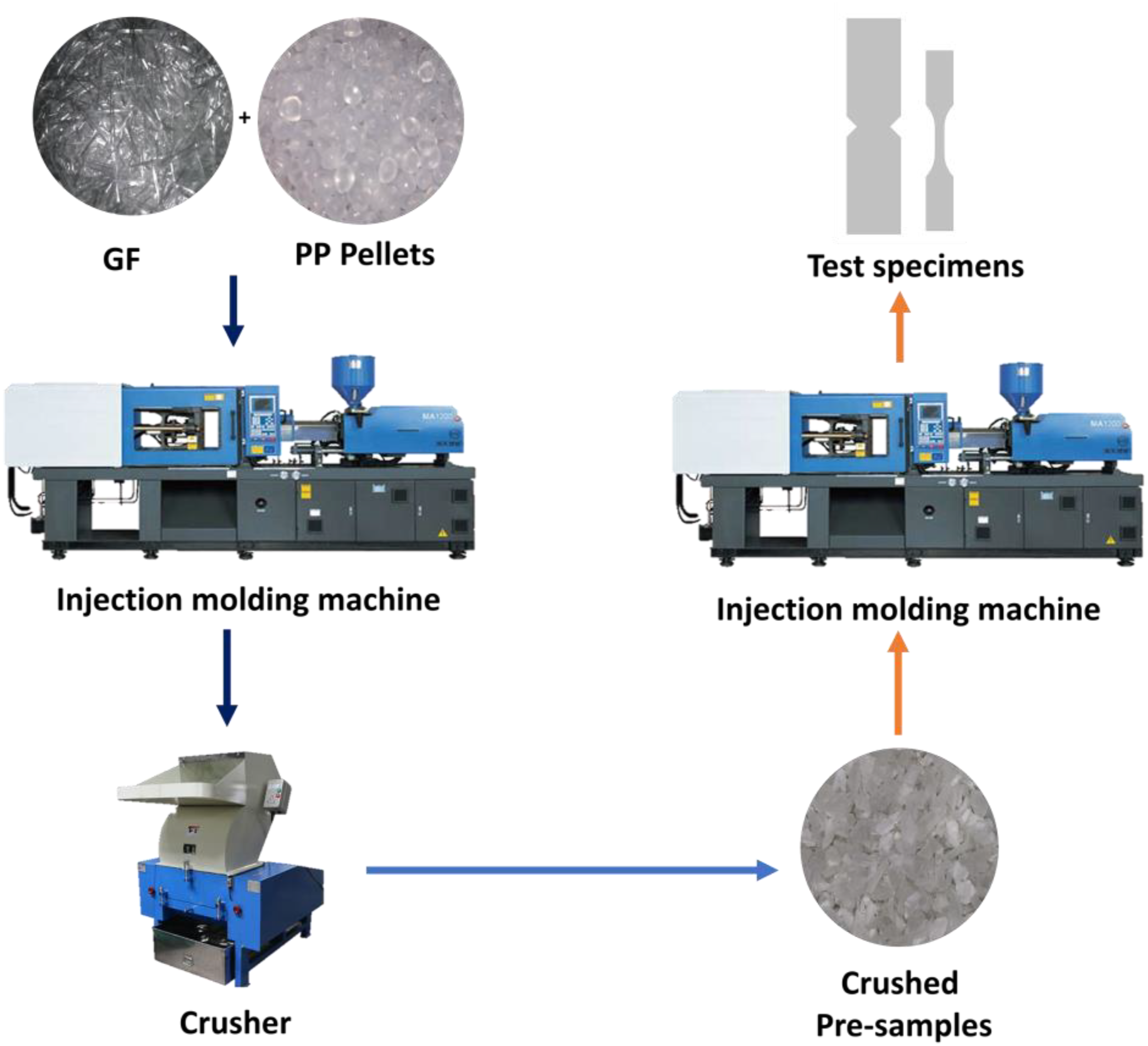
Mold specifications and test specimens
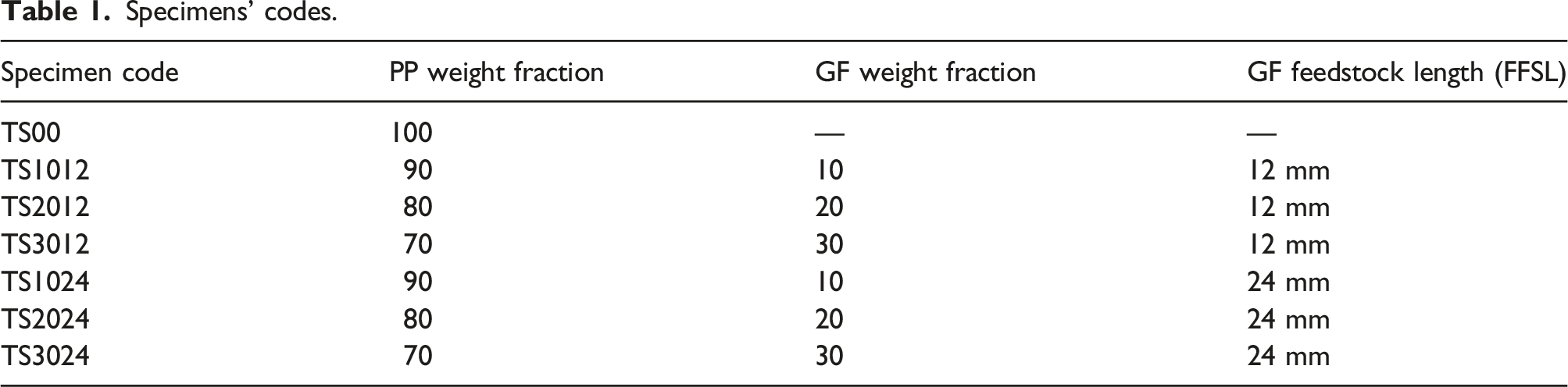
The mold was designed and manufactured especially for producing test specimens of injection molded PP and GF-PP. Several checks were made on the mold to confirm its capability of producing the required test specimens with proper quality. Two types of specimens are produced from this mold; tensile and in-plane shear tests specimens. The tensile specimens are made according to ASTM638, Figure 2(a), while the in-plane shear specimens are made according to ASTM D5379-93,
47
Figure 2(b). The flow direction of the plastic was designed to be in one direction in order to avoid any defects in the product. Test specimens (dimensions are in mm); (a) Tensile test specimen and (b) In-plane shear test specimen.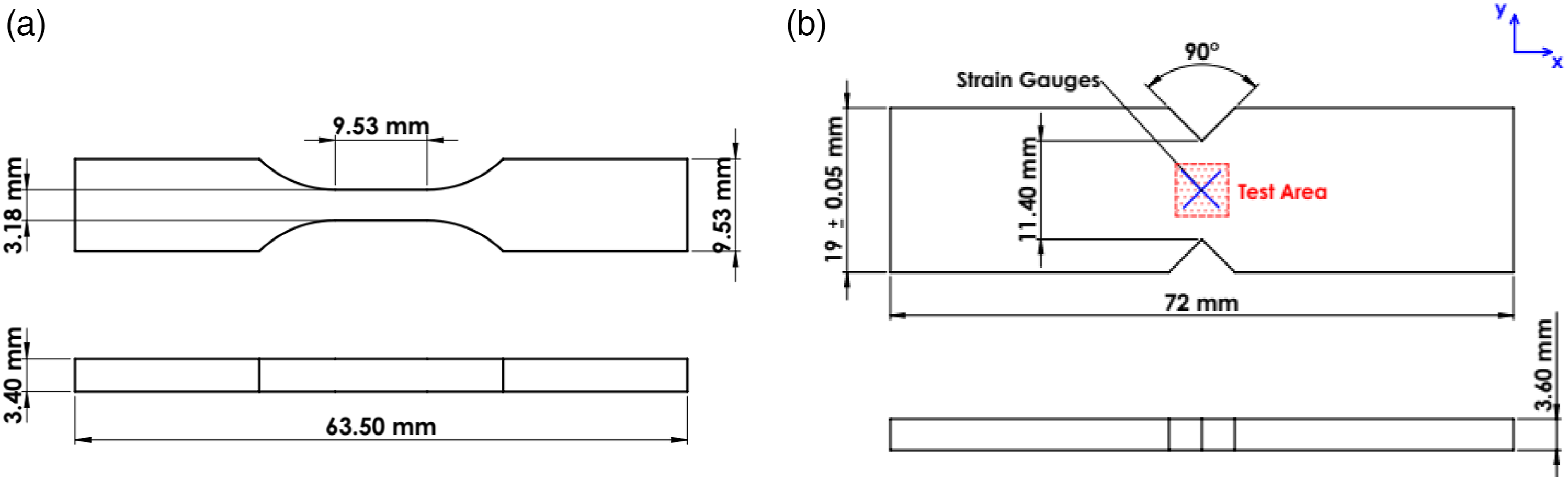
To measure the shear strain (
Tensile and in-plane shear tests
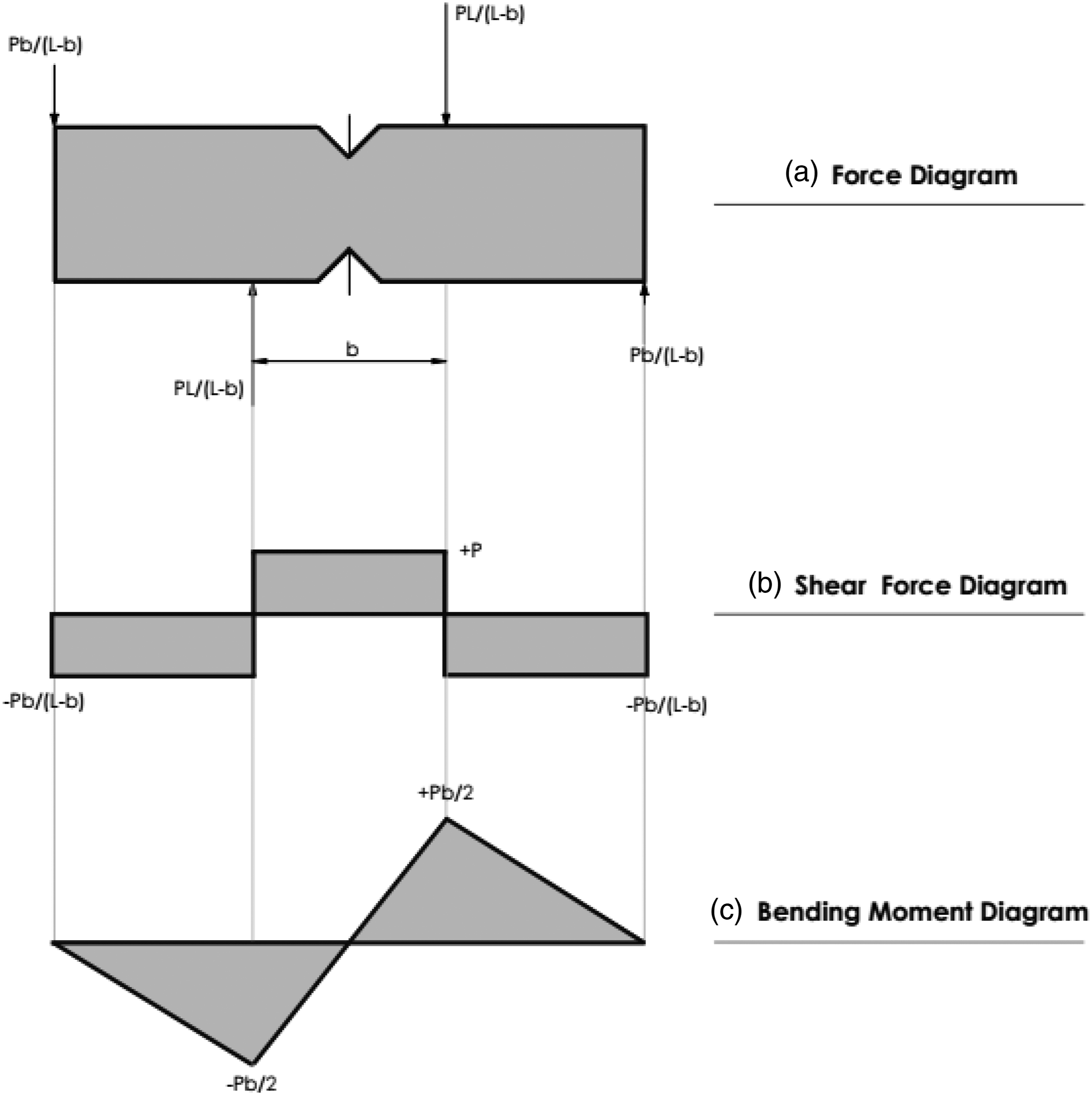
Both tests were carried out on a universal testing machine (Testometric 300 kN). Tensile specimens were simply clamped between universal machine jaws and then the ordinary tensile test is performed. However, in order to perform the in-plane shear test; the specimen was inserted into the fixture with special attention to ensure that the specimen notches were aligned with the loading action line as shown in Figure 3. The notches influence the shear strain along the loading direction, leading to a more uniform distribution of stresses than would be without the notches.
34
By applying two force couples that generate two counter-acting moments, an almost uniform shear stress state is generated at the section between the two notches.
48
The resulting shear and moment diagrams are shown in Figure 4(b) and (c) respectively. A compressive force was loaded normally to the longitudinal axis of the specimen. The crosshead speed of the loading member of the testing machine was 2 mm/min. The load–displacement curves were obtained from the computer unit of the testing machine. Modified wyoming iosipescu test fixture. Idealized force, shear, and bending moment diagrams of iosipescu shear test method. (a) Force diagram. (b) Shear force diagram. (c) Bending moment diagram.
In-plane shear properties (
The left half of the fixture is fixed rigidly to the base plate along with a spacer block which has a guideway to prevent the twisting of the movable (right) half of the fixture. The entire front face of the specimen remains visible during testing and the progress of failure can be monitored visually. Five specimens (with strain gages) were tested for each hybrid and nonhybrid composite type. The shear strains on +45° and −45° planes were measured using Digital Strain Meter Tc-2lk model 232. The scatter of in-plane shear properties (
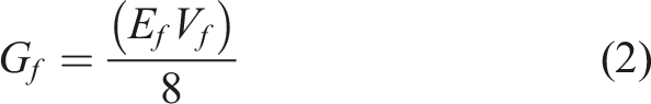
Theoretical prediction of in-plane shear modulus (
)
The in-plane shear modulus (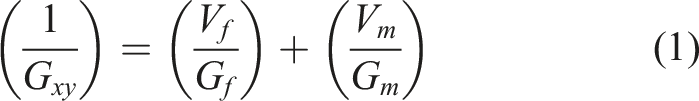
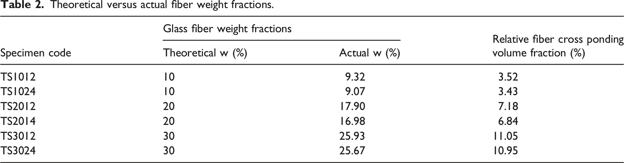
Theoretical versus actual fiber weight fractions.
Results and discussion
Actual weight fractions and fiber lengths
The composite constituents were mixed before the injection molding process with the required weight percentages using an accurate 0.001 scale. Despite that, the weight percentages of the constituents change as a result of the losses in the injection process. Due to this fact, a burn-out test was made on the specimens to check the actual weight fractions of the glass fiber and the fiber lengths in the specimens.
Each composite with different composition was put inside a Porcelain crucible and then weighed using a 0.0001 scale balance (Mettler AE200). The Porcelain crucibles were firstly preheated to ensure moisture removal. The crucibles were then heated inside in a muffle furnace for 4 h at 570°C for a complete PP matrix burn-out. The crucibles were let to cool down to the ambient temperature and then weighed once again. The Vicat softening temperature of the used PP is 150°C and the ignition temperature is 470°C while E-glass fibers have a softening temperature of 850°C and melting temperature of 1140°C. Selecting the temperature of 570°C was sufficient to ensure total burn-out of the matrix and save the fibers to be investigated.
Actual weight fractions
From the weight differences between the crucibles before and after the burn-out process the actual fiber weight fraction could be determined as summarized in Table 2.
From the weight measurements shown in Table 2, it may be concluded that the actual weight fraction of the glass fibers in the resulting composite is always lower than the theoretical weight fraction. It is also noticed that for longer fiber feedstock the weight fraction decreases more than for shorter fibers. The reduction of fiber weight fraction occurs due to material losses. Material losses majorly occur at the initiation of the injection processes and after each injection shot especially because the process was a double-shot injection. Some losses also happen after the crushing process.
Resulting lengths of GF in the composite
The remaining fibers after the burn-out process were captured by a scanner. The scanned photographs were then analyzed using the Fiji ImageJ application to determine the fiber lengths. As previous studies
6
and
51
proposed, number average and weighted average lengths were used to indicate the average fiber lengths in the composite. The relations are expressed as follows Weighted and number average fiber lengths of burn-out two-pass injection molded specimens.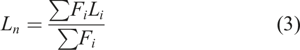
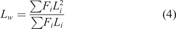
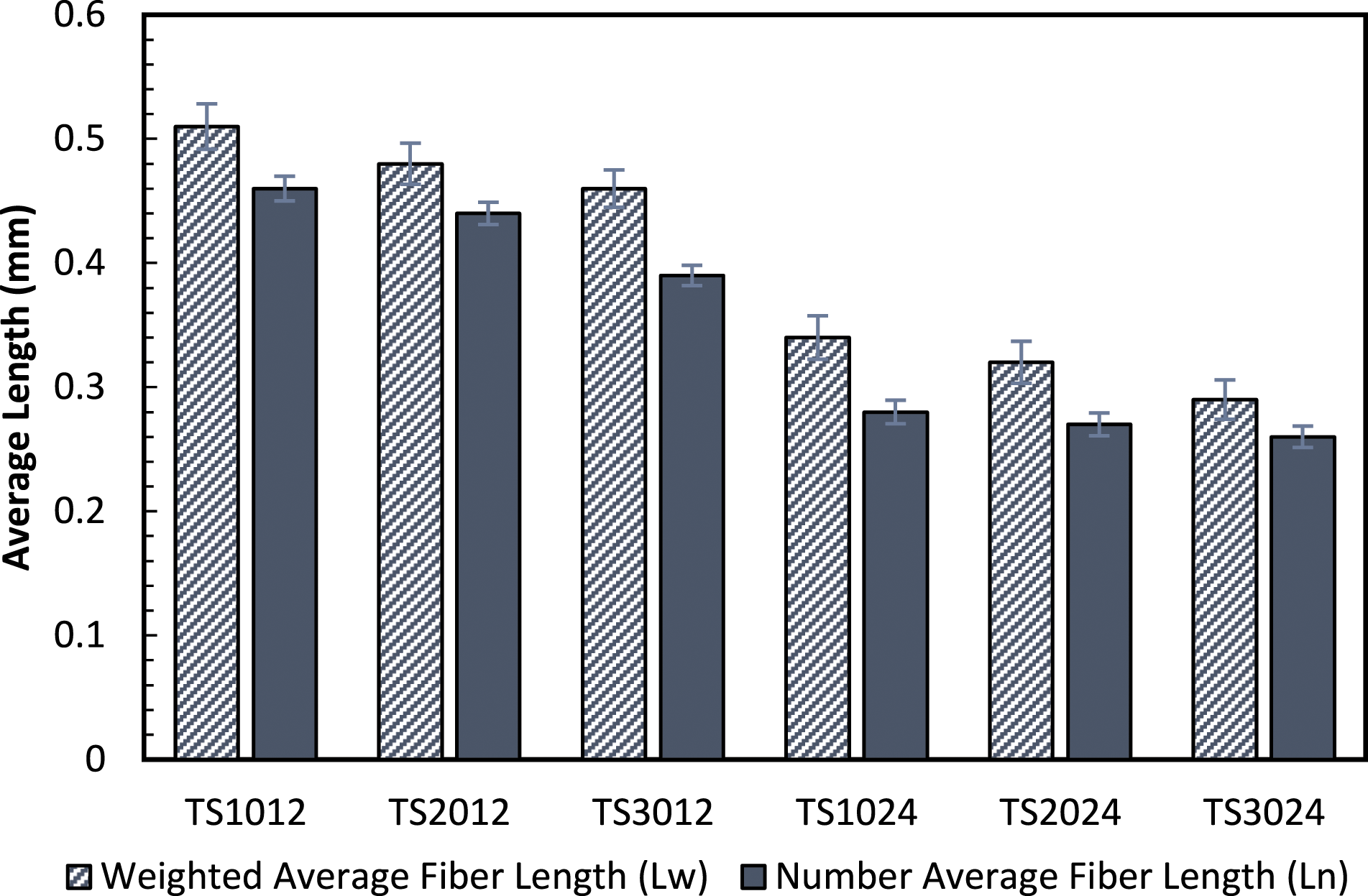
Figure 5 proved clearly that, the fiber lengths decreased dramatically after the injection molding process.6,19,21,23,51–55 The friction of the composite material with both the barrel and the screw generates a dragging flow that produces a compound series of compressive forces, shearing, and differential motion of liquid polymer to the solid counterpart during the solid-to-melt transition. The combined effect enacts severe damage to the GFs. 56
The reduction in the average fiber length of the glass fibers was conducted through three stages. The first stage was through the first injection process as the screw extruder severely damages the fiber during the injection process resulting in a huge reduction in average fiber length. 52 The second stage was the crushing process which also plays a big role in reducing the lengths of the fibers along with composite smashing. The final stage happened in the second injection process while the smashed composite crumbs face the screw extruder once again.23,55
When fiber weight fraction increases a slight decrease in both weighted and number average fiber lengths are observed, Figure 5. This result is also obtained by.19,21,51–53,56 The weighted and number average fiber lengths decrease with increased FFSL. The severe damage to the fiber lengths is majorly linked to the high interaction that occurred between fibers at higher percentages of the fibers in the composite as concluded by Kumar et al.
51
They observed that, when FFSL increases, both
Throughout this work, based on the above results, FFSL of 12 mm and 24 mm will be referred to as “Long Fiber Reinforced Polypropylene (LFRPP)” and “Short Fiber Reinforced Polypropylene (SFRPP),” respectively.
Void content measurements
Specimens’ dimensions were measured using a micrometer then the volume of each specimen was identified. Typically, the dimensional tolerance of specimens was ±0.02 mm for each sample. The specimen’s weight was measured with a Mettler AE200 four-digit balance. Finally, voids content was calculated from weight and volume measurements by using equation (5).
58

From Figure 6 it could be noticed that, air voids increased 2.5 times for LFRPP from TS1012 to TS3012 specimens and 2.7 times for SFRPP from TS1024 to TS3024. Void contents in injection-molded polypropylene and glass fiber reinforced polypropylene.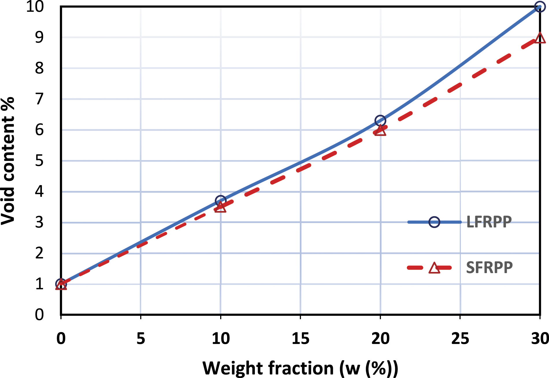
Tensile behavior
Tensile strength
The average of five specimens of each composite composition was taken to represent the tensile strength of this composition. Figure 7(a) represents the tensile strength of neat PP and PP composites with all weight fractions and FFSL. The tensile stress–strain curves for LFRPP and SFRPP are shown respectively in Figure 7(b) and (c). (a) Tensile strength of specimens with different weight fractions, (b) tensile stress–strain curve of LFRPP, and (c) tensile stress–strain curve of SFRPP composites.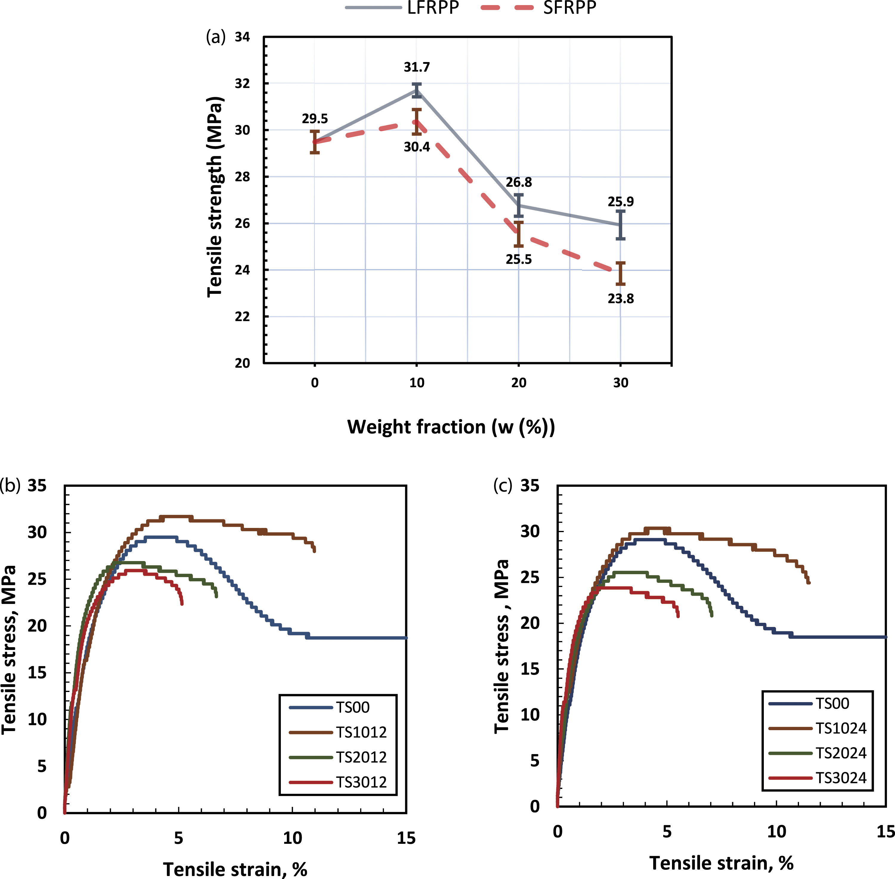
It can be observed from Figure 7 that, the tensile strength increases by the addition of a 10% weight fraction of GF to the PP. Further increase in fiber weight fraction leads to a drop in the tensile strength than neat PP. The first reason behind the non-effectiveness of glass fibers may be attributed to the huge decrease in fiber length in the resulting composite which is also more dramatic at higher weight fractions. The same behavior is noticed for both FFSLs, however, the tensile strengths of composites with shorter FFSL are greater than that of longer FFSL due to an increase in mean fiber length for shorter FFSL. GF of 10% weight fraction in a PP matrix represents the optimum weight fraction at which the highest tensile strength was obtained. This behavior of the composites here expresses glass fibers as filler materials rather than reinforcement materials as they barely increase the tensile strength of the material at w = 10% while the extra addition of GF ruined that increase by dropping the strength below the neat material. The scanning electron microscope (SEM) micrographs of the fractured areas of both TS1012 and TS3012 specimens are shown in Figures 8 and 9. SEM of TS1012 specimen. SEM of TS3012 specimens.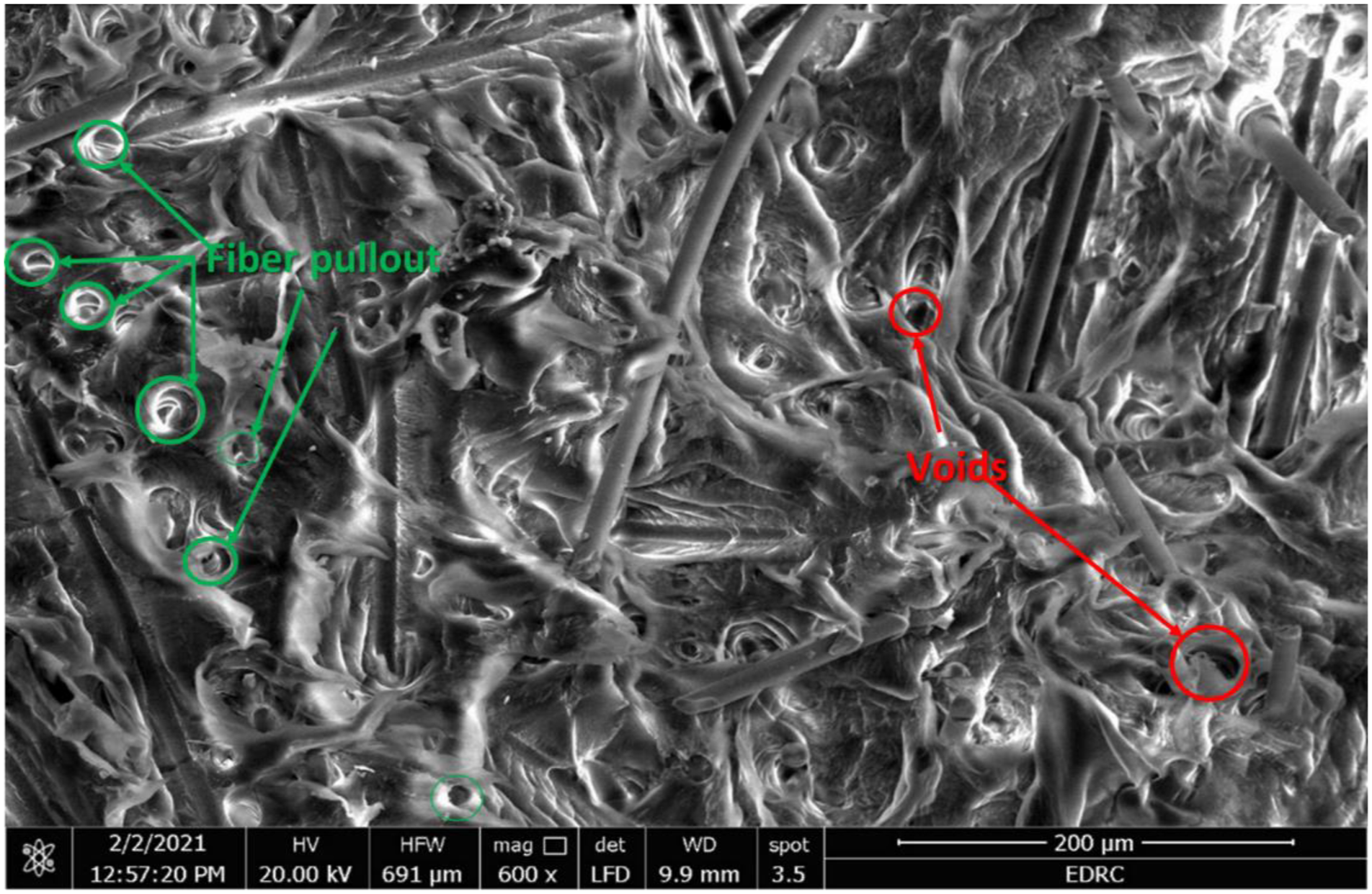
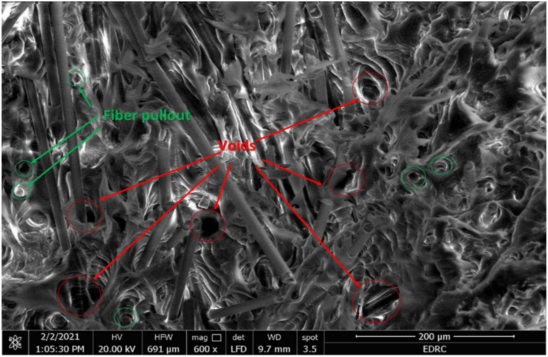
The increase in fiber weight fraction of more than w = 10% increases the probability of air voids generation which weakens the produced composites and decreases their tensile strengths. The combination of the poor effect of the severely damaged fibers and the increased percentage of voids leads the composite tensile strength to decrease at higher weight fractions of fibers. Increased air voids seem to be related to the increase in fiber weight fraction and it may also relate to the repetition of the injection process with step granulation if there is an insufficient time at elevated temperature for the air to be lost from the granules during the second pass of the injection molding machine.
Air voids in the composites can be clearly seen in the SEM micrographs of Figures 8 and 9, where specimen TS3012 has more percentage of air voids than specimen TS1012 as also calculated from equation (3) and shown in Figure 4. Tensile strength was found to be decreasing with increased void content in a previous study by Hagstrand et al. 58
Since the average fiber lengths in composites with longer FFSL are smaller than composites with shorter FFSL, the reduction in the tensile strength of the proceeding composite could be logically accepted. The relation between composite strength and mean fiber length was studied previously by Subramanian and Senthilvelan 6 and Kumar et al. 51 They found that the increase in the mean fiber length in the composites enhances the tensile strength of the composite. Kumar et al. 51 also found that, the effect of the increased number and weighted average fiber lengths on the tensile strength of the composite is higher than the effect of the increased fiber content where the drop in composite strength due to low fiber content could be improved by increasing the number and weighted average fiber lengths.
Tensile modulus
The variation in tensile modulus with the change in the GF weight fraction of GF-PP composites beside the PP specimen is shown in Figure 10. The figure illustrates that tensile modulus increases as a result of reinforcing PP with GF with a maximum improvement in tensile modulus of 247% for the TS3012 specimen compared with the neat PP specimen. Guo and Kethineni
59
observed an enhancement of the tensile modulus of GF-PP over neat PP. Fu et al.
19
noticed a dramatic increase in the tensile modulus of GF-PP as the volume fraction increased. For both FFSLs tensile modulus increases with the increase in GF weight fraction. As mentioned before in the Resulting lengths of GF in the composite section, tensile strengths and moduli of composites with shorter FFSL are slightly greater than that of longer FFSL due to an increase in mean fiber length for shorter FFSL, Figure 10. However, the effect of the fibers’ weight fraction is more significant than mean fiber length. Fu et al.
19
concluded that the tensile modulus of GF-PP is less dependent on the fiber length than on fiber content. Tensile modulus of elasticity of the manufactured specimens.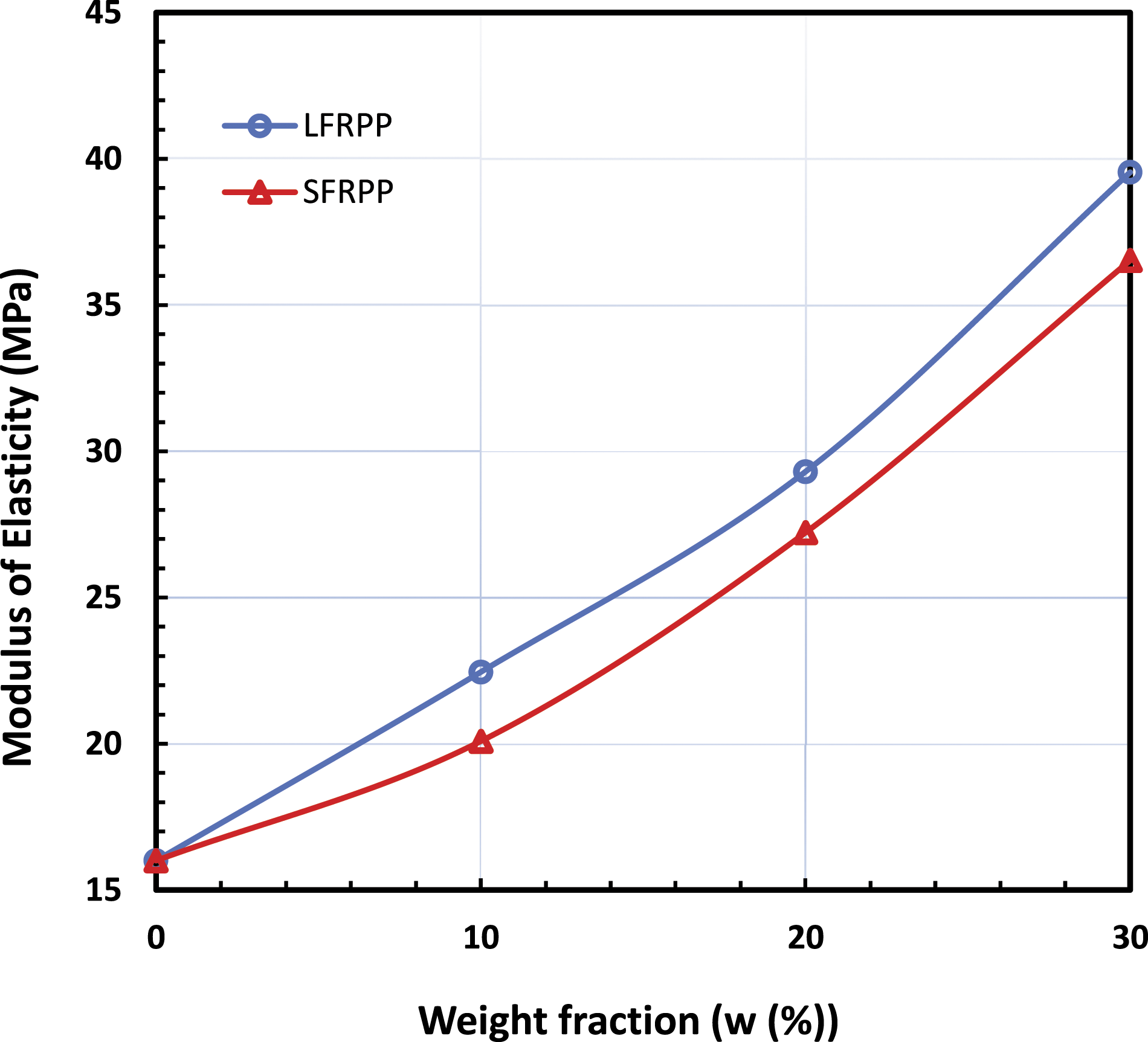
Tensile failure strain
The strain values of each manufactured specimen were determined from the testing machine. The strain of neat PP and GF-PP composites are represented in Figure 11 for each weight fraction and FFSL. As could be noticed from Figure 11, the tensile strain slightly decreases with the increase of GF weight fraction. A dramatic reduction (83.5%) in strain has occurred as a result of reinforcing PP by the chopped glass fiber and further reduction occurred at higher fiber weight fractions. Guo and Kethineni
59
noticed a drop in elongation-at-break once GF were introduced to the neat PP. The drop in the tensile strain values is attributed to the effect of the embrittlement that occurred due to the improvement in the tensile modulus of GF-PP as shown in Figure 10 where the development of matrix cracks at the ends of the reinforcing fibers has been assumed to be the cause of this phenomenon.
19
Moreover, as both FFSLs have almost the same behavior, Figure 11, tensile strain is obviously not affected by the change in FFSL in the current investigation. The change in FFSL affects the resulting fiber lengths, as explained before in the Resulting lengths of GF in the composite section, nevertheless, the amount of change in the fiber lengths between LFRPP and SFRPP is not great enough to highlights the effect of the change in fiber lengths on the failure strain values. However in a previous study, Karsli and Aytac
60
found superiority in strain at break values in favor of longer fibers in carbon fiber reinforced Polyamide 6 as they have reduced number of fiber ends in the composite. Fiber weight fraction versus strain of the manufactured specimens.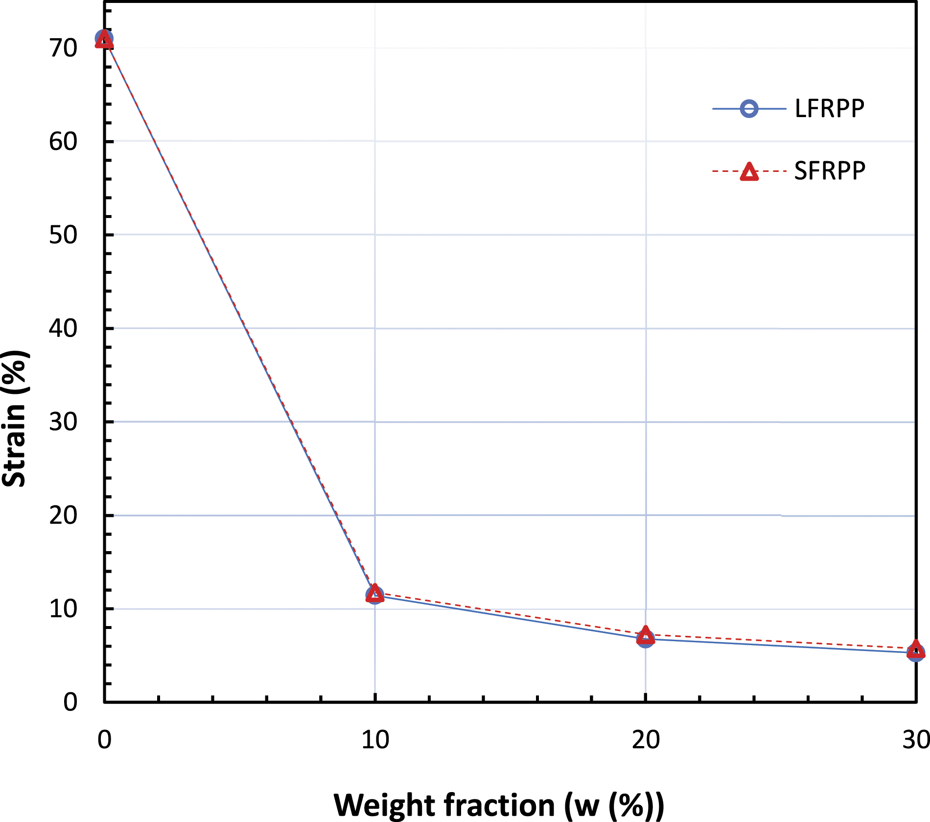
The development of matrix cracks at the ends of the reinforcing fibers has been determined to be the cause of this phenomenon. The ends of shorter fibers then gradually develop additional cracks when the strain is raised. This cracking can initially be tolerated by transferring load to nearby fibers that “bridge” the broken area. Final failure happens when the amount of cracking in a specimen’s weakest area reaches a threshold level at which point the surrounding fibers and matrix are unable to support the growing stress.61–63
In-plane shear properties
In-plane shear strength
The in-plane shear strength of PP and GF-PP are shown in Figure 12. As observed from the figure, the shear strength values of all specimens are very close where neglectable variation in strengths are observed that are not exceeding 2.2 MPa. Considering these variations, the strength values increased slightly as the weight fraction increased for both LFRPP and SFRPP. However, LFRPP composites have slightly higher values at similar weight fractions. The slightly increased in-plane shear strength of the composites with longer fibers was also noticed by Raj and Nandhini.
48
These results of shear strengths may not present the complete influential effect of the fibers’ weight fraction on the shear strength of GF-PP. Specimens do not have the chance to carry the actual endurable load within the narrow test region and once the deformation exceeds the area limit, the specimen touches the fixture fixed-grip where a material-to-material contact occurs forming a fake increase in the load, as concluded by He et al.
32
in Iosipescu shear test technique. He et al.
32
concluded that the Iosipescu test is more applicable in measuring specimens’ shear modulus than the shear strength. In-plane shear strength of polypropylene (PP) and glass fiber reinforced (GF-PP).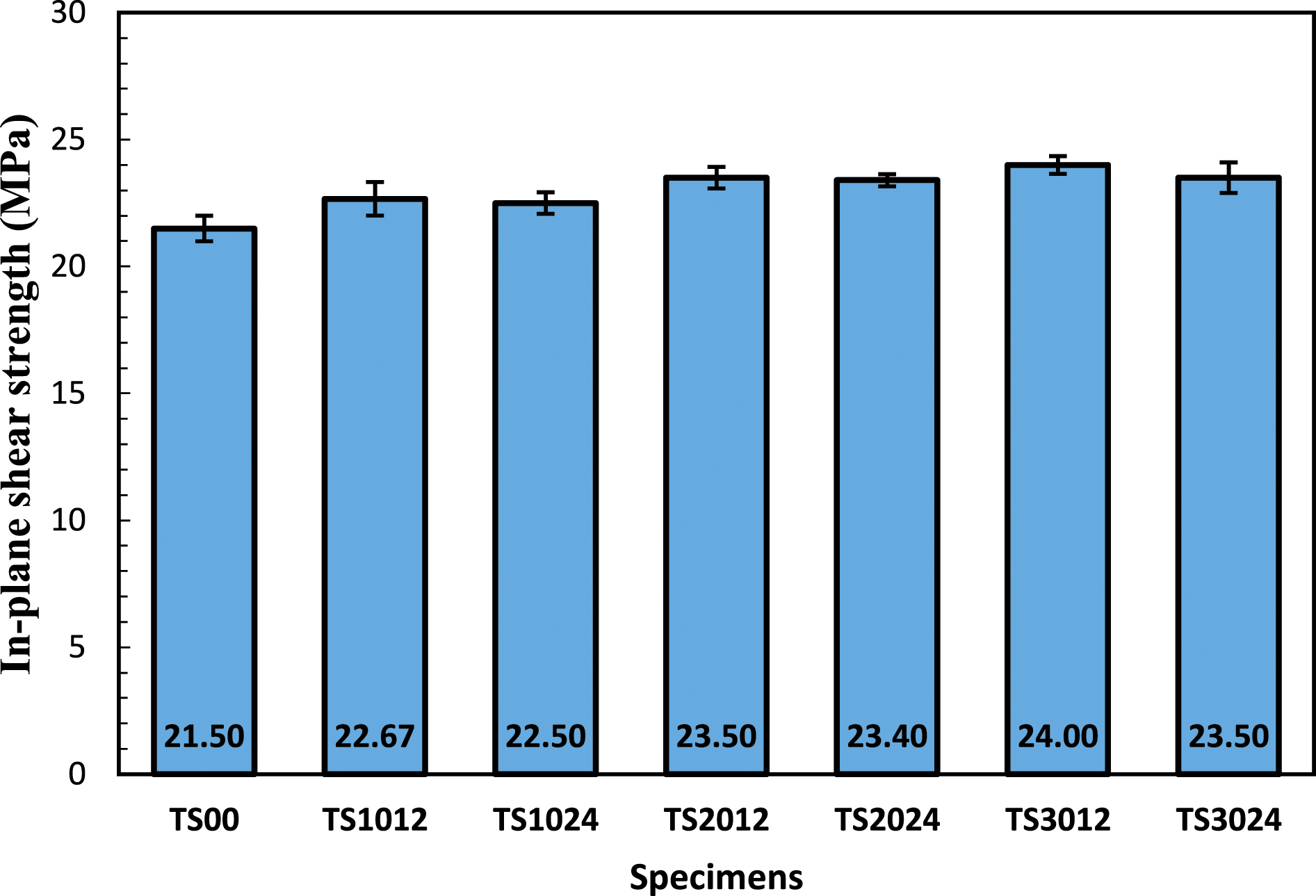
In-plane shear modulus
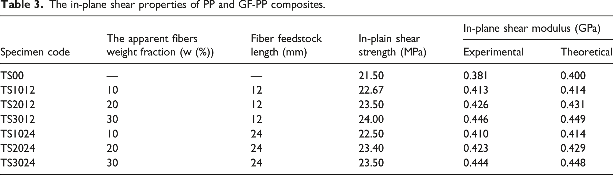
Figure 13 shows the relationship between the shear stress In-plane shear stress ( In-plane shear stress ( Experimental and theoretical values of the in-plane shear modulus of polypropylene (PP) and glass fiber reinforced PP (GF-PP).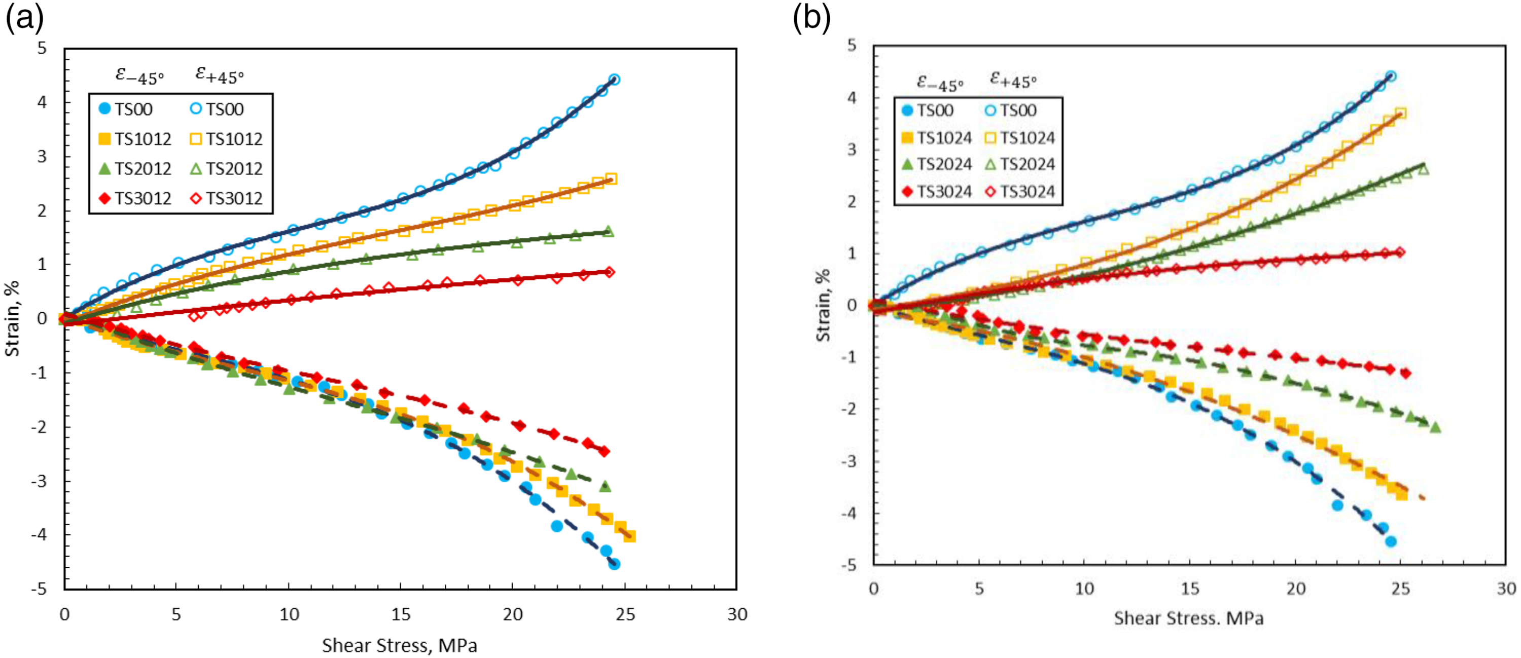
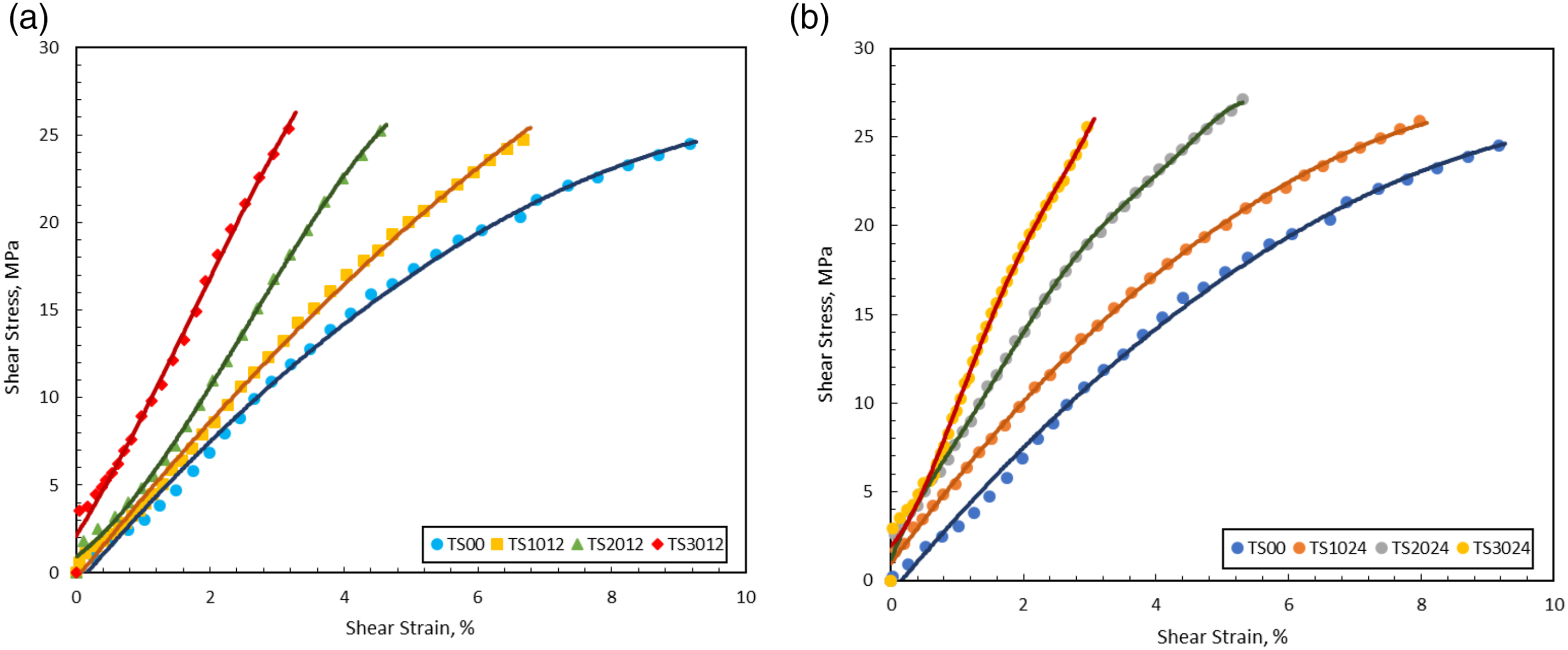
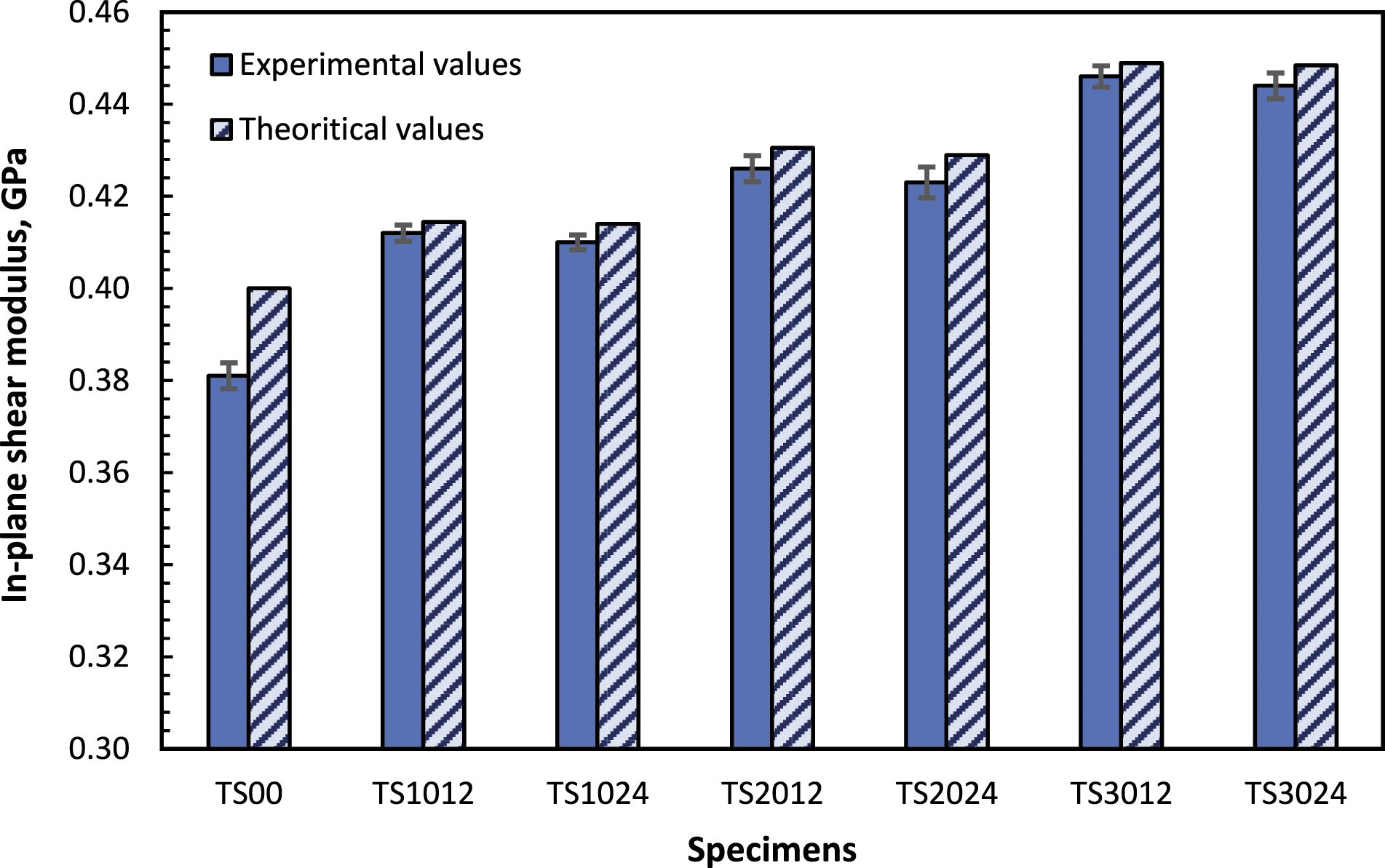
The in-plane shear properties of PP and GF-PP composites.
Fracture mechanisms
Tensile fracture mechanisms
Tensile fracture mechanisms of the tested specimens (TS00, TS1024, TS2024, and TS3024) are shown in Figure 16. TS00 specimens showed localized necking with great ductility where they remain un-fractured all along with the tensile test. All other specimens showed some form of ductile fracture. The addition of chopped GF to PP with different weight fractions hugely reduces the ductility of neat PP. A similar observation was obtained by Guo and Kethineni.
59
Specimens after tensile test; (a) TS00, (b) TS1024, (c) TS2024 and (d) TS3024.
In-plane shear failure modes
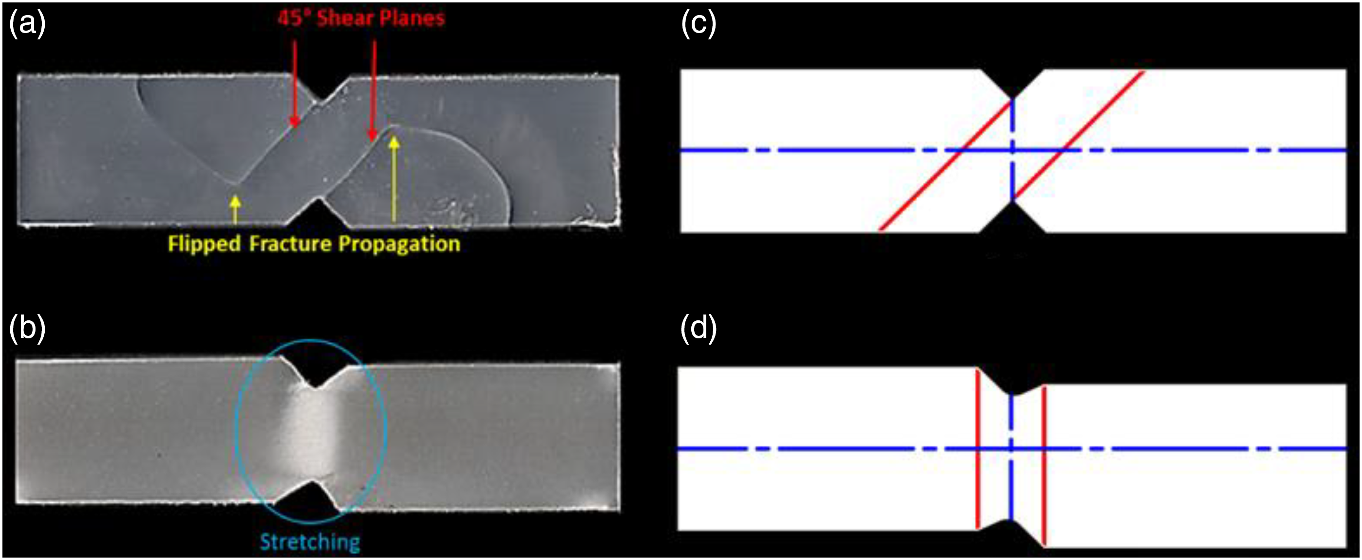
The fracture modes observed after the in-plane shear tests are represented in Figure 17. Neat PP specimens were cracked in two parallel 45° planes from the V-notch and propagated across the specimen, Figure 17(a). The fracture propagation directions were flipped due to continued unbalanced loading after fracture occurrence. However, all GF-PP specimens failed under the same failure mechanism irrespective of weight fractions and fiber lengths. GF-PP specimens were stretched plastically following the loading direction without any surface cracks, Figure 17(b). Liu and Piggott
65
found that most of the thermoplastics simply stretched and sometimes cracked in 45° planes when introduced to Iosipescu in-plane shear test. Typical failure modes for thermoplastics as observed by Liu and Piggott
65
are represented in Figure 17(c) and (d). Failures obtained from in-plane shear tests for (a) PP, (b) GF-PP, and typical failure modes in the iosipescu test for most thermoplastics at 25°C: (c) mode 1 and (d) mode 2.
65
Conclusions
This work investigated the in-plane shear and tensile properties of PP and GF-PP composites produced by the injection molding technique which was conducted using two passes. Based on the experimental results, it could be concluded that; • The tensile strengths increased for the higher values of the mean fiber lengths. The resulting fiber length could be controlled by choosing appropriate initial fiber lengths. • The tensile strength increased when PP was reinforced with w = 10% GF. Further increase in weight fraction tends to decrease the tensile strength rather than increase it, where specimens with w = 20% and 30% GF had strengths lower than neat PP. • The high concentration of the air voids (2.5–2.7 times increase) and intensely shortened fibers weakened the composite and led to deterioration in the tensile strength. • Severe deterioration of 83.5% in tensile strain had occurred as a result of reinforcing PP with the chopped glass fiber irrespective of the GF weight fraction. • The tensile modulus of elasticity increased as a result of reinforcing PP with GF with a maximum improvement of 147% for the TS3012 specimen compared with the neat PP specimen. • In-plane shear strength of PP was slightly increased along with increasing fiber weight fractions with an enhancement percentage of 109% and 111% for SFRPP and LFRPP, respectively. • In-plane shear modulus was also enhanced for GF-PP up to 17% of neat PP, and the percentage of enhancement increases with the farther addition of glass fibers. The experimental values agreed with their theoretical counterparts.
Footnotes
Declaration of conflicting interests
The author(s) declared no potential conflicts of interest with respect to the research, authorship, and/or publication of this article.
Funding
The author(s) received no financial support for the research, authorship, and/or publication of this article.