
Abstract
Thermoplastic composite sheets have great potential for use in industrial applications owing to their fast-forming properties in the mold. One of the important matters of forming is the tendency of the part to recover elastically after it comes out of the mold. This behavior affects the dimensional accuracy of the final part. In this study, V-bending experiments were carried out to understand the spring-back phenomenon of continuous glass fiber-reinforced polyamide-6 composite sheets. Unidirectional and cross-ply composite sheets were used in the experiments and bending angle, die radius, pressure, and dwell-time were investigated systematically. After bending, the spring-back angles of the parts were measured and the effects of the inspected parameters were compared. Also, variations in part thickness caused by spring-back were evaluated. Finally, the deformations in the specimens resulting from the residual stress were visualized with a scanning electron microscope. When the results were compared, it was determined that the bending conditions where the spring-back defect could be minimized were 6 mm radius, 90° angle, 120 s dwell-time, and 3 MPa pressure. Under these situations and in sheets bent 90°, the amount of spring-back was determined as 22° for unidirectional composites and 15° for cross-ply composites.
Keywords
Introduction
Precautions taken to reduce the share of industrial factors on climatic changes necessitate technological developments in the automotive sector. 1 In the automotive industry, where costs sensitive to production volume are important, short cycle time manufacturing methods and appropriate material classes are being developed. 2 Concordantly, studies on vehicle weight reduction have come to the fore recently. In this context, continuous fiber reinforced thermoplastic composite sheets with high specific strength are replacing sheet metals with high density. 3 Sheet metals are used in vehicle body panels, interior surface plates, and structural elements such as carriers, holders, and casings. 4 These components are manufactured by such rapid forming techniques as cutting, bending, flange-edging, rolling, deep drawing, etc. 5 It is aimed to use continuous fiber reinforced thermoplastic composites for these vehicle parts, where strength, as well as lightness, is required. Thermoplastics show their properties such as low density, easy workability, ductility, and bendability in the composite structure. 6 Thermoplastic composites have great potential for use in mass production industries because they can be made into flat sheets, are solid at room temperature, and can be stored as semi-finished products for a long time. Also, they are suitable for manufacturing rapid final parts by thermoforming processes like stamping. 7 The stamping process is the final shape of solid or semi-solid flat sheets by pressing them between the mold. The flexibility of the material, which takes the shape of the molding profile in a process such as bending, is an important factor affecting the quality of the part. 8 In order for this material option to become widespread in the automotive industry, some of its obscurities must be systematically determined. Within this scope, the effects of the bending method, which is frequently used in the manufacture and forming of vehicle parts, on thermoplastic composite sheets were investigated in this study. As in sheet metals, and thermosets, the problem of spring-back arises in the part after the bending process in thermoplastic composite sheets. In addition, residual stresses that cause spring-back can lead to early damage to the matrix structure. 9 Overcoming this difficulty is important in terms of dimensional accuracy and geometric tolerance of the final vehicle part.
Bending is the process of forming the material around an axis, with or without the aid of heat, without machining. In the bending process, a part of the material moves precisely in a different direction, keeping its cross-section as much as possible. 10 In order for bending to take place, the elastic limit of the material must be exceeded and permanent deformation must occur. Compressive stress occurs in the inner part of the neutral axis of the bent material and tensile stress occurs in the outer part. When a force is applied to the material that is intended to be bent, the inner surface of the material tries to shorten and the outer surface tries to lengthen. If the elastic limit of the material is not exceeded, the material is restored when the force is removed. If the elastic limit of the material is exceeded, the neutral axis shifts slightly to the bending center, and permanent deformation occurs. 11 The bending force must be greater than the resistance of the material against it. If the flexibility limit of the material to be bent is exceeded but the maximum resistances are not overcome, when the applied force is removed from the material, the inner surface tries to be tensile a little bit and the outer surface tries to be compressive. This is called spring-back. 12 The ratio of the post-bending part angle to the initial bending angle is defined as the spring-back factor, and a value equal to 1 indicates no deformation. The difference between the bending angle and the part angle after bending is expressed as the spring-back angle. In some conditions, spring-back may show up in the opposite direction, which is also described as spring-forward. 13
In forming thermoplastic composite sheets, the material is molded by heating to operating temperature and left to cool. Meanwhile, the matrix with large thermal expansion tries to contract, and this behavior is tried to be prevented by the fiber which shows almost no thermal expansion. This causes internal stresses (tensile and compression) in the composite material. With the removal of the forming load from the material, residual stresses develop in the material. The most common effects of residual stresses are defects such as delamination and spring-back. 14 For composite materials, the properties of the matrix, such as temperature resistance, and moisture retention, and the bonding forces at the matrix and fiber interfaces play a role in residual stresses. Moreover, especially in composite sheets, residual stresses are caused by defects such as fiber misalignment, cracking, delamination, and warpage and the mechanical properties of the sheet. Furthermore, the process conditions such as the structural shape, thickness, fiber orientation, fabrication technique, tool radius, tool-part interaction, consolidation pressure, and time of the composite affect the residual stresses. 15 Researchers often use experimental methods, such as the bending test, to investigate the dimensional instability of the sheet to be formed.
In order to determine the spring-back behavior, 2-D forming operations such as U-bending, V-bending, and S-bending, which are widely used in sheet metals and recently applied to polymer composite sheets with minor modifications, are performed. In this context, the studies carried out to solve the defects, such as spring-back, delamination, and tearing, occasioned by bending with different cross-section tools of thermoplastic composite sheets are reviewed below.
In the research conducted by Srinivasan et al. on the forming of 5 mm-thick chopped wood reinforced thermoplastic composites, it was reported that the ratio between the punch radius and the sheet thickness affects the spring-back defect and this ratio should be 3 for the most suitable bending. 16 Rao et al. fabricated semi-hexagonal and sinusoidal profiles by extrusion from short natural fiber reinforced composite plates for use in the core of honeycomb composite panels. Specimens were prepared from polypropylene composites consisting of 30% by weight sisal fiber as parallel, and perpendicular to the extrusion direction. Bending operations were carried out at different tool radii, angles, specimen temperatures, and press speeds. The bending characteristic was better at high forming speed and at temperatures close to the melting point of the polymer. Superficial breaks were detected in the part bent perpendicular to the extrusion direction, and fiber separations were detected in the part bent parallel to the direction of the extrusion. The bending part with multiple curves had less spring-back compared to the single-groove bend with the free edge due to the incremental edge constraint. A rise in the bending interior angle led to an increase in spring-back, and a decrease in the interior angle caused spring-forward with an increase in speed and temperature. 17 Padovec et al. formed the composites in a paired mold and examined the dimensional changes caused by residual stresses in the part that cooled down after being removed from the mold. They suggested that dimensional changes occur in the form of angular spring-back of the sheet section, warping of the planes, and displacement of the layers. They compared the effects of different carbon fiber alignments and the number of layers on the U-section bending of composite sheets. The die radius was increased together with the number of layers, and the spring-back angle could be kept constant at almost 2.5°. 18 Jamin et al. studied the forming of carbon fiber reinforced polyphenylene sulfide composite sheets by pressing. The effects of the composite fiber configuration, sheet thickness, tool radii, temperature, compression pressure, and dwell-time parameters were investigated on the quality of the part bent in S geometry. The mechanical performance of the specimens was evaluated with four-point bending tests. The strength of the specimen decreased with the increase in the radius of curvature. 19 Ozaki et al. investigated the effects of bending conditions of carbon fiber reinforced polycarbonate sheets on part dimensional stability and deformations. The composite sheets were bent in a cap form at different specimen temperatures between the glass transition and the melting points. The spring-back occurred in the part bent at the glass transition temperature and angular deformation was prevented as the temperature increased. 20
The performance of rapid forming technologies (i.e. stamping) aroused the interest of Lu et al., and they conducted one-stage bending experiments to fabricate curved beams from thermoplastic composite sheets. Aluminum plate, carbon fiber, and polyether-ether-ketone films were stacked and the potential of these sandwich composite panels to take the V-shape was investigated. The effects of punch speed and temperature were searched on the bending part. The bending temperature and punch speed with the least spring-back, thickness variation, and defects were revealed as 380°C and 10 mm/s. 21 Engel and Brühmann investigated the spring-forward and spring-back mechanisms of fiber reinforced thermoplastics. In order to optimize the bending process of the composites, deformations caused by residual stresses in the part were investigated due to conditions such as interlayer shear, anisotropic thermal expansion, and crystallization. Woven glass fiber reinforced polyamide-6 composites were bent into a V-shape at 90° angle, at various tool radii and speeds. Even in single-layer composite plates, spring-back was discovered and the elastic strain of the fiber and/or the heterogeneous temperature change was shown to be the cause. The unreinforced polymer plates contracted inward after bending. 22 Zal et al. produced glass fiber reinforced poly (vinyl chloride) composite sheets at different orientations through the ply stacking method and formed them in a U-bending mold. Inter-ply shearing mechanisms and spring-back conditions of the bending composites were evaluated. The main defect in bending occurred as fiber buckling. The spring-back was less in 45°/–45° woven composite compared to 0°/90° woven composite. The residual stresses decreased when the bending temperature was increased to 160°C. In addition, the sandwich composites prepared by putting an aluminum plate in the core of the composite exhibited more spring-back phenomenon than the others in the same bending process. 23 Zaidan et al. subjected polypropylene composite sheets reinforced with different fiber ratios to V-bending experiments and examined the effects of varying forming temperatures on the spring-back deformation of the part. The spring-back factor was suppressed with the increase in forming temperature. The spring-back angle decreased as the glass fiber ratio increased. The smallest spring-back value was achieved when 40% fiber reinforced composite was bent at 100°C. 24
Distortions caused by residual stresses (shrinkage, spring-back, etc.) in thermoset matrix composites due to long curing-cooling processes are the most common problems and there are many studies on epoxy resin composite materials in the literature.25–27 On the other hand, studies on the two-dimensional forming of thermoplastic composite sheets are summarized above. In current studies, carbon fiber or natural fiber reinforced composites are in the majority. Glass fiber reinforced composites, which have attracted great interest in the automotive industry, are the subject of this study because they are more economical than carbon fiber, meet the strength requirement adequately, and are not hydrophilic like natural fibers. 28 Polyamide-6, one of the most widely used thermoplastics, was preferred as the matrix element of the composite sheet.
In this study, the rapid forming performance of continuous glass fiber reinforced polyamide-6 composite sheets was discussed and the amount of spring-back caused by residual stress during two-dimensional forming was investigated. The effects of the fiber stacking constituting the composite sheet structure were examined on the bending performance. Unlike previous studies, a series of V-bend operations were performed via dies that have various tool radii and angles. Also, the effects of dwell-time and pressure of bending were also researched in order to minimize the deformation magnitude. In addition, changes in part thickness were measured. Moreover, the final situations of the bent parts (geometric distortion, mesocrack, delamination) were evaluated by photomicrography.
Materials and methodology
The materials considered in this research are continuous glass fiber reinforced polyamide-6 composites. Composite sheets, which are manufactured by the compression molding method and are currently used in different industrial areas, were supplied ready-made. Prepregs containing unidirectional glass fiber were stacked at 0° and 0/90° directions and formed into two different structures as shown in Figure 1. The cross-ply composites were laid-up unsymmetrically in a [0/90]6 sequence. The areal weight of E-type glass fiber with a mass ratio of 60% is 430 g/m2. The thickness of each prepreg is 0.25 mm. Composite sheets with a thickness of 3 mm were fabricated using 12 prepregs per sheet. Structures of the unidirectional (left) and cross-ply (right) composites.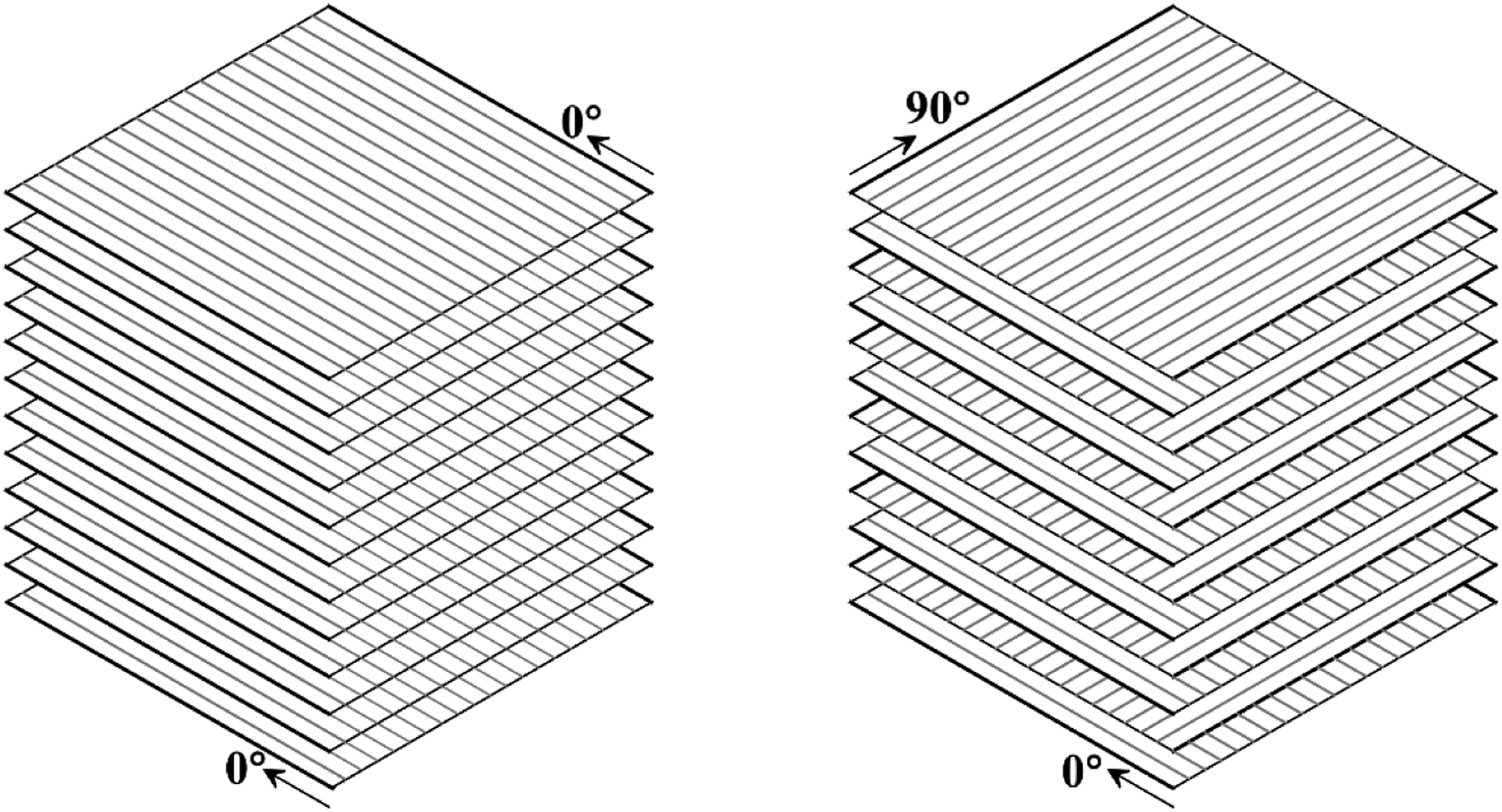
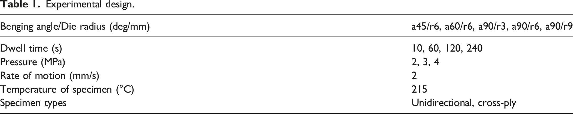
Specimens prepared in sizes of 20 × 60 mm2 to be used in bending tests were cut on a water-jet bench. Five types of bending die sets were designed in order to compare the effects of bending angle and bending radius. The die sets manufactured with 0.5% tolerance on the CNC (Computer Numerical Control) machine are shown in Figure 2. Tools have 45-degree, 60-degree, and 90-degree angles with a 6 mm radius, as well as a 90° angle with 3 mm and 9 mm radii. The positive and negative dies have the same radius and angle. Guide pillars were placed by making bushes on both sides of the dies, thus ensuring that the motion is concentric. A flow curve was given to the beginning of the die cavity in order to facilitate the movement of the specimens in the die and to prevent additional stress deformation in the sheet. Matching dies.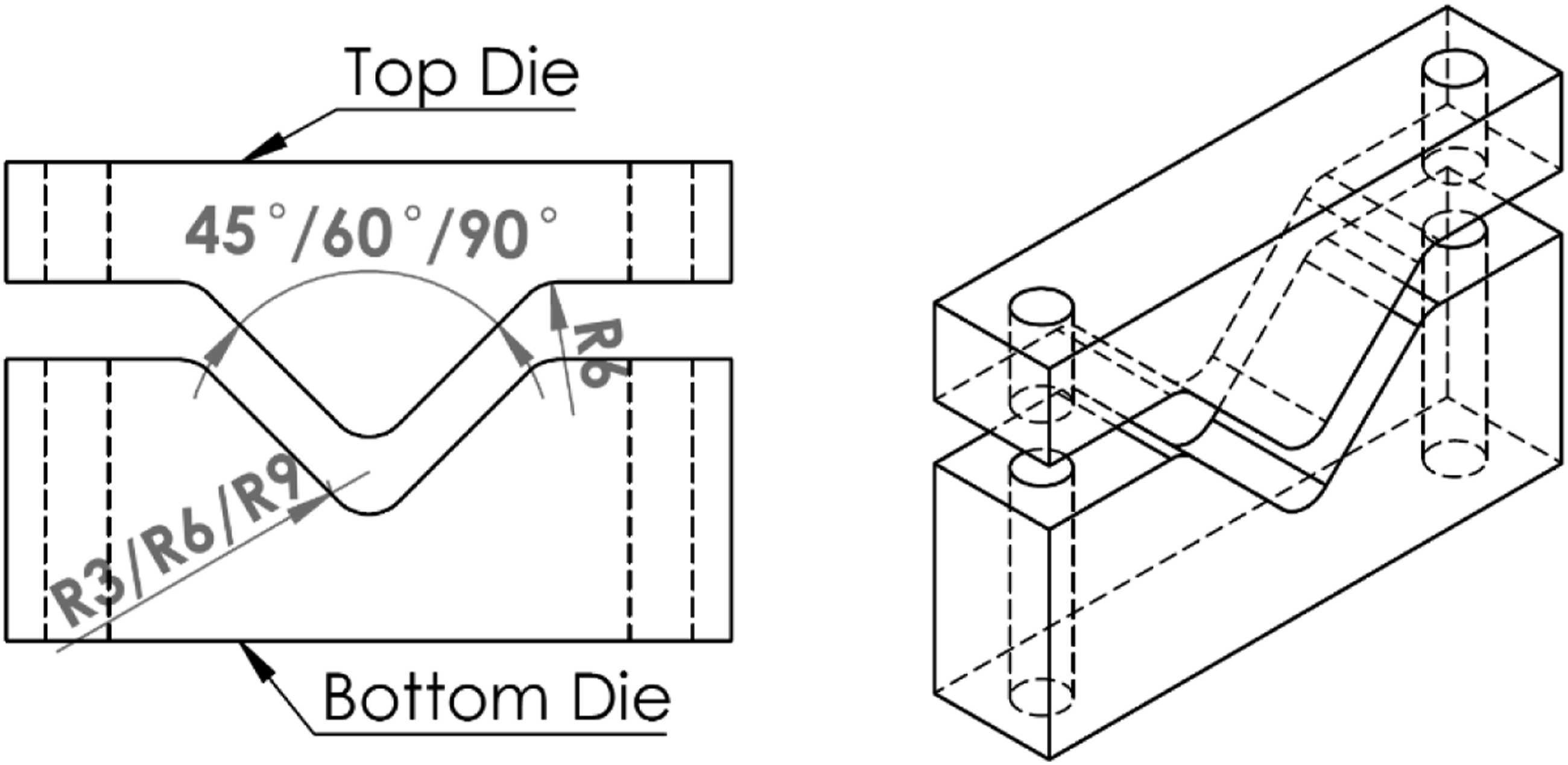
The modularly prepared bending dies were mounted on a special hydraulic press machine as seen in Figure 3. One of the die matches was fixed on the table and the other was displaced with the movable cross-beam of the machine. The system was controlled by PLC (Programmable Logic Controller). Before starting the tests, the machine’s calibrations (displacement, speed, force, pressure) were made, and parallelism was adjusted for the tools to apply equal pressure around the part. Schematic diagram of the experimental setup.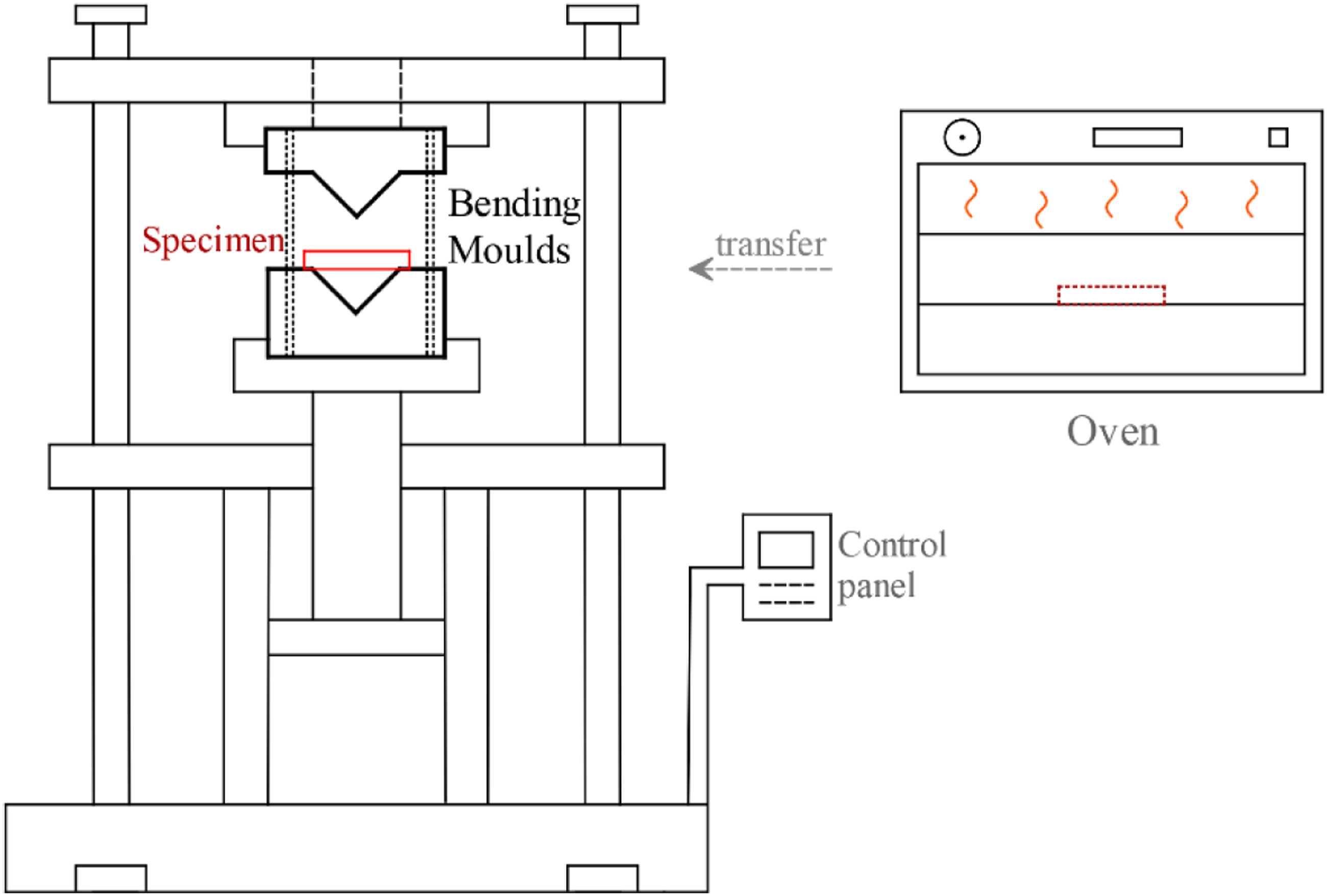
Experimental design.
The final bending angle of the 2-D formed part was measured with a gauge 3 h after exiting the die. Figure 4 shows the angle gauge used to measure the amount of spring-back of bent specimens. The parts were placed from the bending center to the origin of the protractor and after the waiting/cooling period, the final state of the parts was photographed from the top view. While the specimens were placed on the protractor, the bottom surface of the specimens was referenced to zero degrees. At the end of the planned time, the angle change of the outer surface was measured. The measured angle values were recorded for all specimens. The accuracy of the angle indicator is ±0.25°. Then, the thickness values were measured from 3 different sections, namely the curve-center region, the ramp region, and the flange region, with the help of a digital micrometer, and the percent change of the thickness according to the initial was calculated. Finally, sample parts selected from each parameter were imaged at the same scale under 15 kV voltage with IXRF Systems Inc brand Scanning Electron Microscope (SEM) device and deformations were examined. To avoid electrical charging, samples were coated with gold/palladium in two sets (60 s, 10-8 Pa, 8 mA) in a Polaron brand device before scanning. Circular protractor for gauge spring-back angle.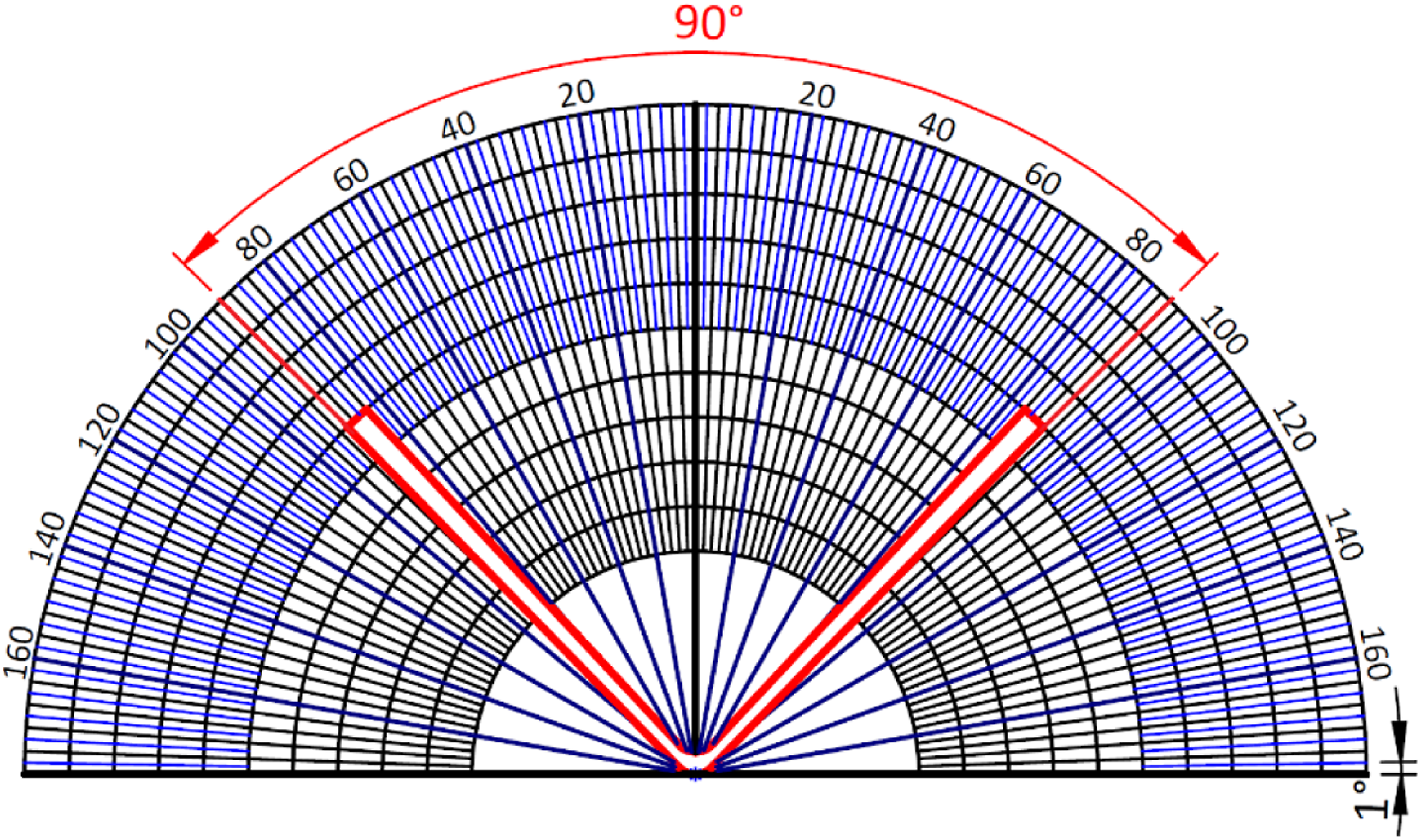
Results and discussion
Spring-back behaviour
In the preliminary experiments, the samples were photographed immediately after being taken out of the die and at 30-minute intervals, and it was discovered that the bending angle did not change after the second hour under room conditions. Therefore, the spring-back angles of the parts were recorded 2 h after bending.
Figure 5(a) and Figure 5(b) show the spring-back angles measured after the unidirectional composite sheets were bent in the die with an angle of 90° and a radius of 6 mm. While the bending pressure was changed to 2, 3, and 4 MPa, the dwell-time was changed to 10, 60, 120, and 240 s. It was determined that the increase in both bending pressure and dwell-time reduces the spring-back. Because of the increase in pressure, the shear deformation of the composite layers was suppressed and with the increase in the dwell-time, the residual stresses were spread evenly throughout the composite sheet. When the dwell-time was 10 s and the bending pressure was 2 MPa, the bending amount of the composite sheet bent 90° was recorded as 35°, and when the pressure increased to 4 MPa, this value decreased by 9° and became 26°. While the bending pressure was 4 MPa, increasing the dwell-time from 120 s to 240 s did not change the amount of spring-back and was determined as 21°. As the dwell-time increased, the effect of the pressure on the spring-back decreased. It was concluded that the most suitable dwell-time is 120 s. Engel and Brühmann
22
also reported similar findings and explained that the rate of heat loss of the part between the mold or in the ambient air is different and that low dwell-time increases residual stresses depending on anisotropic cooling. In addition, parallel to the results here, Hwang et al.
31
determined that as the operating temperature increases and the holding time increases, the deviation of the part stamped at a 90-degree from the reference angle decreases. (a) Change in spring-back angle with respect to bending pressure (Unidirectional, 90° angle, 6 mm radius) (b). Change in spring-back angle with respect to dwell-time (Unidirectional, 90° angle, 6 mm radius).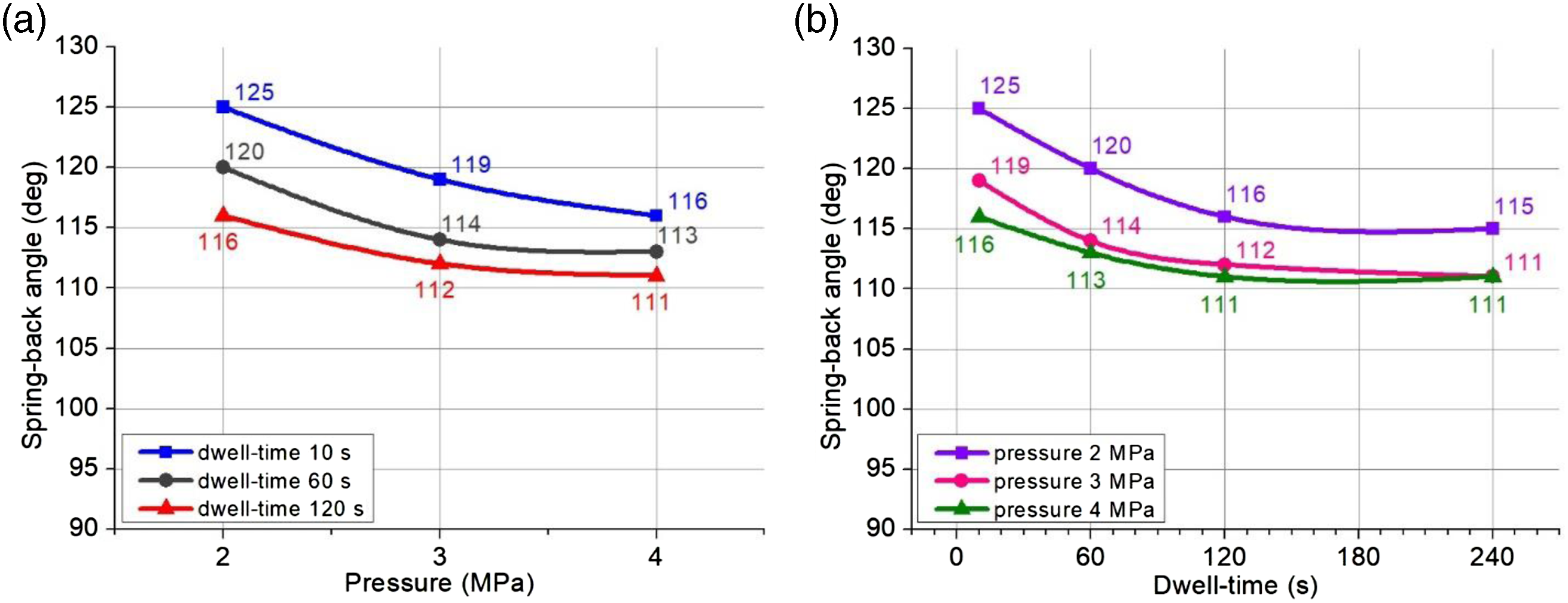
Figure 6(a) and Figure 6(b) show the effect of different die radii on the spring-back angle of the unidirectional composite sheet bent at 90°. While the radius values change to 3, 6, and 9 mm, the effects of dwell-time and pressure are also shown. When the dwell-time was increased from 10 s to 120 s, there was an average 7% reduction in spring-back. It can be explained that the significant decrease in the spring-back angle with the increase of the dwell-time is due to the fact that the semi-crystalline material spends the time it takes to complete the phase transition in the mold, and under particular pressure. The maximum spring-back was 38° in bending with 2 MPa pressure and a 9 mm radius. Increasing the pressure from 3 MPa to 4 MPa reduced the spring-back by an insignificant amount, 1°. The die radius of 3 mm made the shear strength resistance to the section thickness dominant in the composite sheet. Mahzan et al.
32
declared in a similar study that small tool curvatures increase the intensity of the stresses at the bending center of the composite sheet and accordingly increase the spring-back. Since the sharp-edged deformation processes cause an increase in the regional intensity of the residual stresses, the spring-back was high in the bending of the material with a radius of 3 mm. The die radius of 9 mm triggered the shear strength resistance between the layers of the composite sheet. The large curvature and therefore the emergence of delamination increased the spring-back. It was concluded that the most suitable die radius is 6 mm. In another similar study, Jamin et al.
19
stated that the pressing force is more important at small radii. (a). Change in spring-back angle depending on die radius and dwell-time (Unidirectional, 90° angle, 3 MPa pressure) (b). Change in spring-back angle depending on die radius and bending pressure (Unidirectional, 90° angle, 120 s dwell-time).
Figure 7 shows the relationship between bending angle, die radius, and bending pressure of the cross-ply composite sheet with spring-back. While the die radius was kept constant at 6 mm, the bending angle was changed to 45°, 60°, and 90°. It was established that the amount of spring-back decreased linearly as the angle increased and was recorded as 37°, 26°, and 15°, respectively. When the bending angle was kept constant at 90°, the die radius was changed to 3 mm, 6 mm, and 9 mm, and the spring-back amounts were measured as 17°, 15°, and 18°, respectively. When the radius was reduced, the fibers arranged in two directions were buckled, and the residual stress increased. When the radius got bigger, the elastic limit of the material could not be exceeded enough, and the tendency of the composite sheet to return to its original state increased. Therefore, it was concluded that the optimum die radius is 6 mm in the symmetrical bending of the 3 mm thick cross-ply composite sheet. While the die radius was 6 mm, the bending angle was 90°, and the pressure changed to 2 MPa, 3 MPa, and 4 MPa, the spring-back angles took 19°, 15°, and 14° values, respectively. The increase in bending pressure especially affected the fiber spread in the curve region, and the matrix migrated out of the profile with the movement of the fiber. In this case, it reduced the amount of spring-back by providing local displacement of the residual stresses. Effect of bending angle and die radius on the spring-back angle for the cross-ply composite sheet.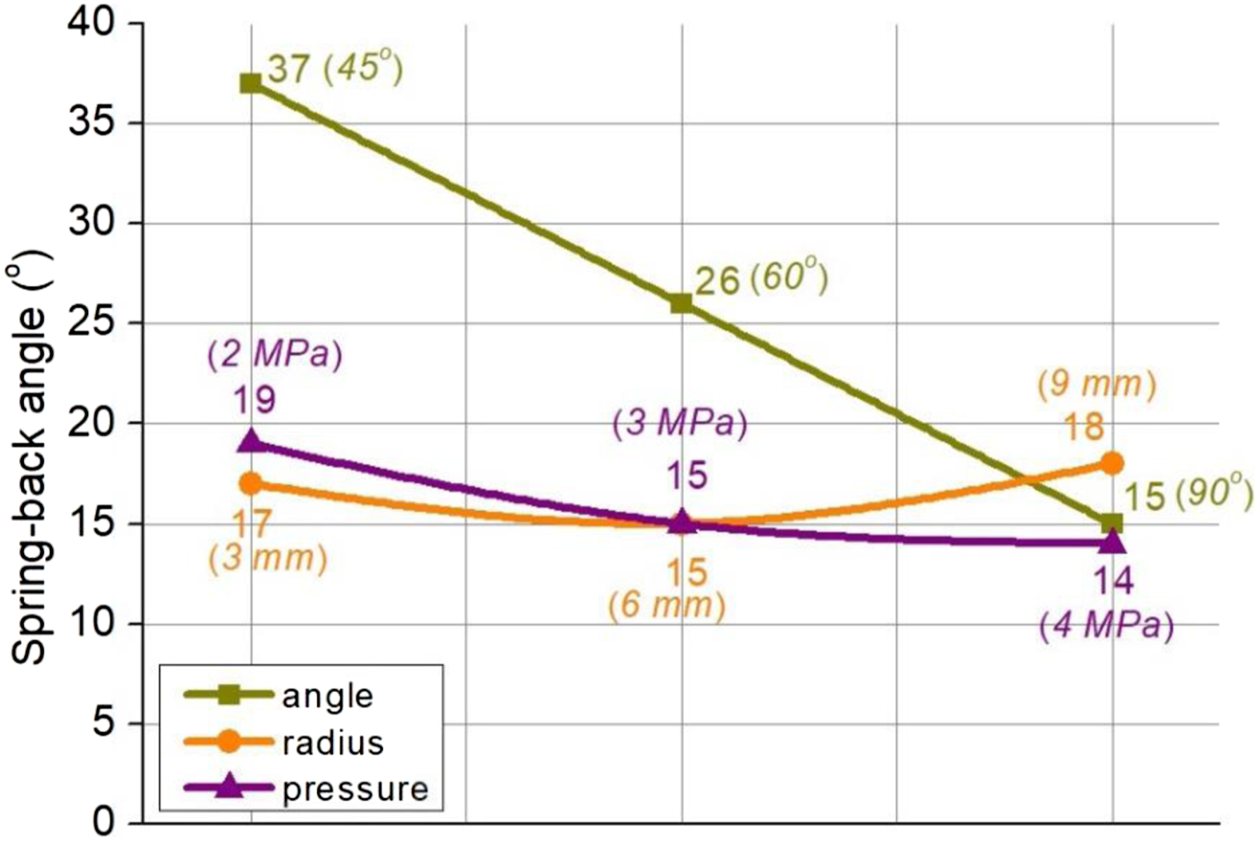
In Figure 8(a) and Figure 8(b), the spring-back behavior of unidirectional and cross-ply composite sheets were compared at 3 MPa pressure and 120 s dwell-time. It was found that as the bending angle decreases, the amount of spring-back of the composite sheet with two different structures increases. However, the spring-back of the cross-ply composite was smaller than the unidirectional composite in all experiments. The improved mechanical properties of cross-ply composites provided an advantage in terms of residual stresses. The fact that the fiber direction of the layers has both 0° and 90° arrays limited the shrinkage strains of the sheet in both directions, thus ensuring less spring-back. For the same die radius, the bending angle change affected the spring-back angle between the two types of composite sheets at different rates. With the doubling of the bending angle, the spring-back decreased from 47° to 22° in the unidirectional composite and decreased from 37° to 15° in the cross-ply composite. For this reason, the spring-back difference between the composite sheets increased from 21 to 32% when the bending angle increased from 45° to 90°. Due to the high shear resistance between the layers of the cross-ply composite, the decrease in spring-back with the increase of the bending angle was greater than that of the unidirectional composite. It was concluded that the optimum bending angle with the least spring-back for both composite sheets was 90°. The change in the radius value played a more pronounced role in the spring-back of the unidirectional composite. If the radius value was equal to or three times the sheet thickness, the spring-back angle difference between the two types of composites was equal to 37%. (a). Variation of the spring-back angle according to the bending angle (6 mm radius, 3 MPa pressure, 120 s dwell-time). (b). Variation of spring-back angle according to die radius (90° angle, 3 MPa pressure, 120 s dwell-time).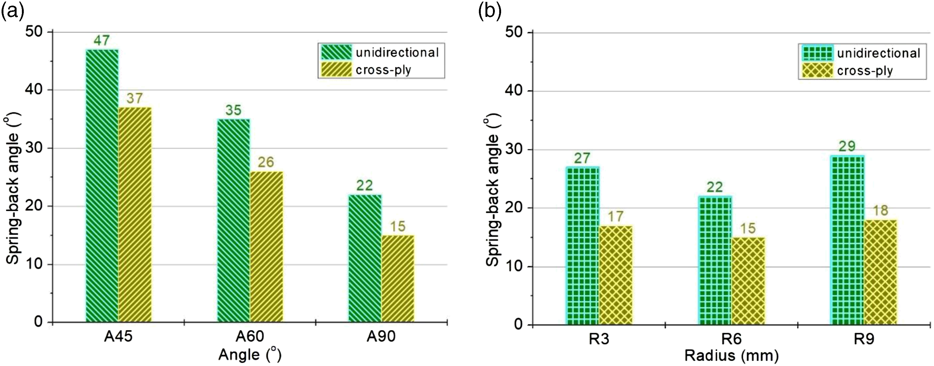
Two types of folding defects occurred during the V-bending process of composite sheets. The first of these is that the bent part cannot take the V-shape symmetrically. This defect was caused by the large clearance in the 90-degree mold and the short specimen length. The second defect is irregularly buckling across the specimen section. This defect arose in cross-ply composites. A bit too much sheet thickness causes this defect. Damaged specimens were not taken into account in the calculations. New experiments were done instead of defective specimens.
Thickness distribution and deformations
The two-dimensional shape was given to unidirectional and cross-ply composite sheets, which were subjected to bending in dies with various angles and radii and at different pressures and dwell-times. Changes in part section thickness caused by spring-back deformation after bending were detected. In Figure 9, the sections where the thickness values were measured are shown and it is depicted that the section narrowing between the dies differs according to the bending angle. A homogeneous thickness is expected throughout the formed part. However, this expectation is not entirely possible in practice. One of the things that cause this is the geometrical state of the bending die. The specimen starts to compress in different regions between the paired die during bending. The die geometry affects the movement mechanism of the specimen in the die and accordingly, it also affects the shearing behavior between the layers of the composite sheets. Another factor affecting the thickness is the thermal and physical change of the specimen during the bending process. Since the cooling between the composite layers cannot be controlled uniformly, there is a difference at the beginning of the crystallization of the layers. This causes distortions and spring-backs in the composite sheet. Crystallization is more in the region where the cooling takes place slowly and therefore the material exhibits a more brittle behavior. On the other hand, low crystallinity occurs in the fast cooling region.
33
Hence, the temperature gradient varies through the thickness and there are differences in the section thicknesses along the composite sheet. Measurement regions of specimen cross-section and comparison of the horizontal clearance distances between dies at any-moment.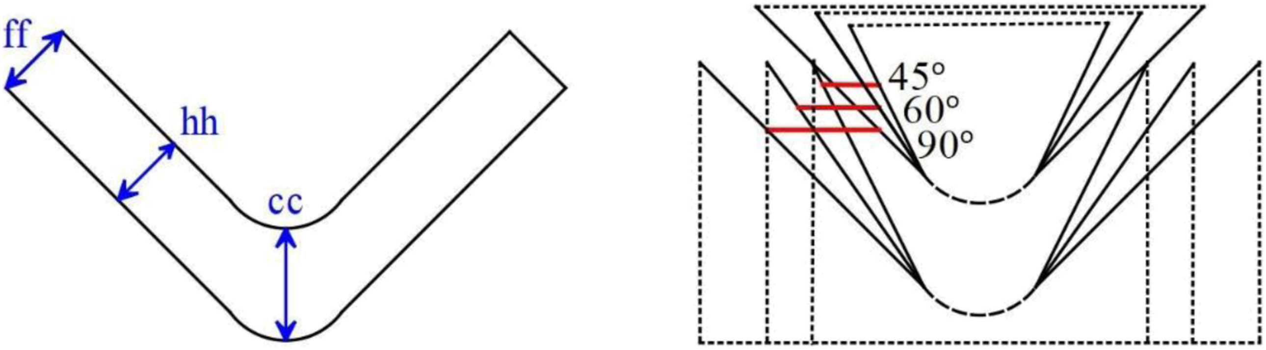
In Figure 10, the thickness values measured from different sections of unidirectional composite sheets bent at 90° angle, 6 mm radius, and 3 MPa pressure conditions are shown with percentage distribution. Region numbers on the horizontal axis, 1 and 5 represent the flange sections, 2 and 4 represent the ramp sections, and 3 represents the curve-center section. It was observed that the dwell-time was most effective on the section thickness in the center, then on the flange, and partially on the ramp. The inadequate dwell-time increased the heterogeneity of the part thickness. The lowest thickness values were measured from the ramp section and this section corresponds to the region where the horizontal distance between the die pairs is the least. Thickness distribution of specimen sections in terms of dwell-time (Unidirectional, 90° angle, 6 mm radius, 3 MPa pressure).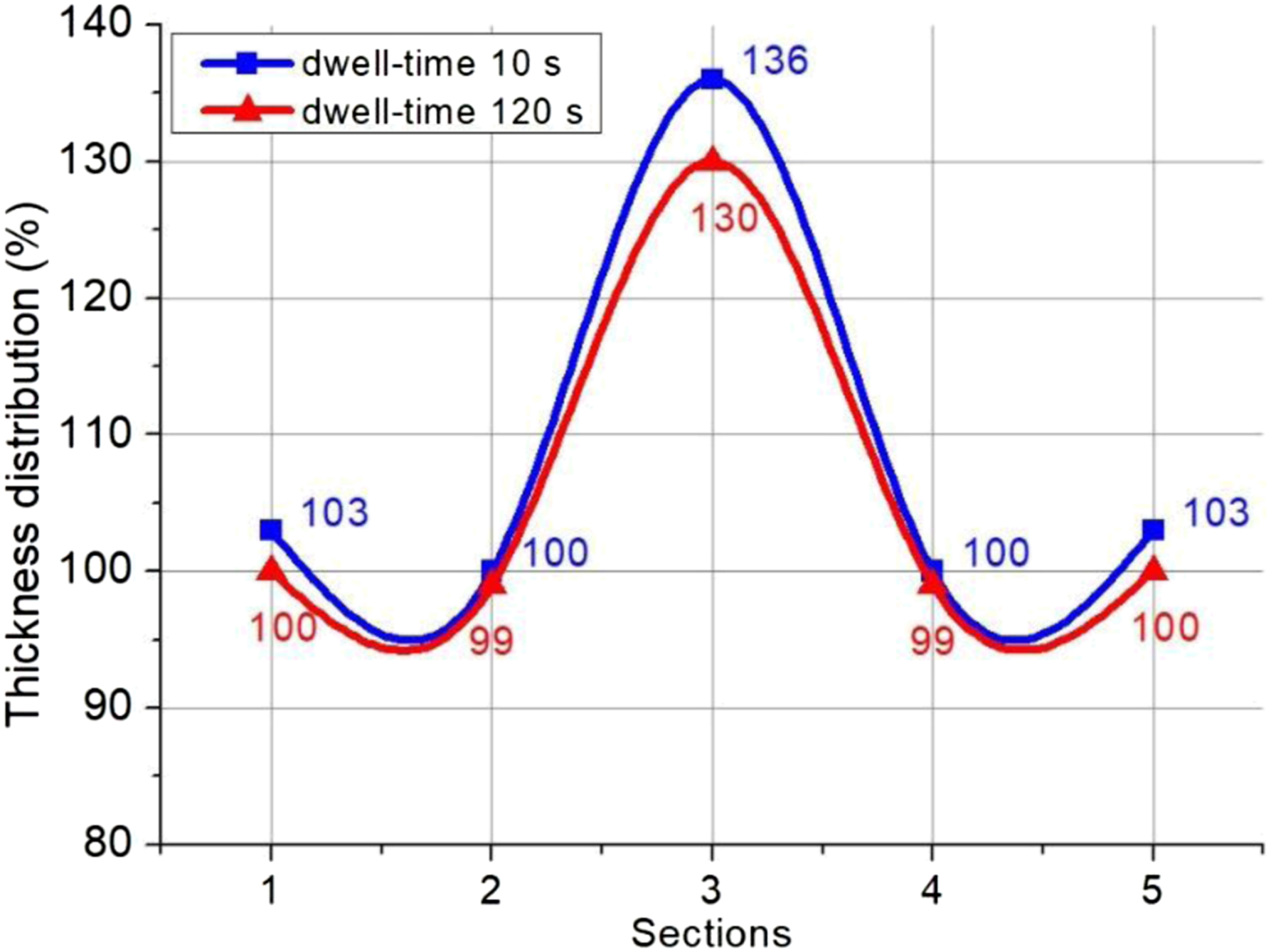
The change in section thickness of unidirectional composite sheets according to the bending pressure is shown in Figure 11. Different bending pressures applied to the specimen changed the part thickness between 0.03 and 0.24 mm. As the pressure increased from 3 to 4 MPa, the part thickness changed by less than 0.12 mm. Although the pressure of 2 MPa was sufficient to give the desired form to the composite sheet, it could not prevent the formation of corrugation in the bending center and the delamination at the flange. When the pressure was increased to 4 MPa, the thickness of the ramp and flange regions decreased. The optimum thickness distribution was obtained in the bending process with a pressure of 3 MPa. The thickness values in the central region were higher than expected. However, this thickness value was recorded as high due to the fiber kinking and lamina buckling towards the inside of the neutral axis. Nevertheless, on the outside of the neutral axis, defects such as fiber breakage, which may be caused by tensile stress, did not occur in any parameter except for 45° bending. When the stamping pressure increased, the internal voids in the composite sheet were eliminated as argued also by Gong et al.,
34
thus reducing the warpage and thickness variation after demolding. Thickness distribution of specimen sections in terms of bending pressure (Unidirectional, 90° angle, 6 mm radius, 120 s dwell-time).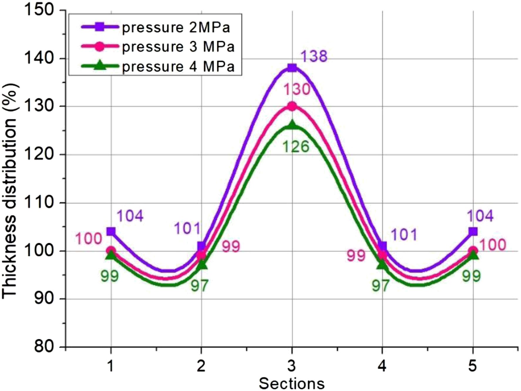
In Figure 12(a) and Figure 12(b), the percent thickness changes of the composite sheets measured from the flange region and the curve-center region are shown. After bending, it was determined that the cross-ply composite deviated from the initial thickness more than the unidirectional composite. This result is caused by layers of fibers that cross to the bending direction perpendicularly. As the bending angle decreased, the flange section thicknesses of both composite sheets increased linearly. The variation of the die radius changed the flange thicknesses up to 4% in the cross-ply composite and less than 2% in the unidirectional composite. When the thickness increase measured at the curve-center was examined, the least change was determined as 28% in the bending process with a 90° angle and 9 mm radius. Inward folds and crushing occurred at the center of both cross-ply and unidirectional composites. Angle change was more effective than radius change. (a). Thicknesses of specimen flange versus bending angle and die radius (3 MPa pressure, 120 s dwell-time) (b). Thicknesses of specimen symmetry axis versus bending angle and die radius (3 MPa pressure, 120 s dwell-time).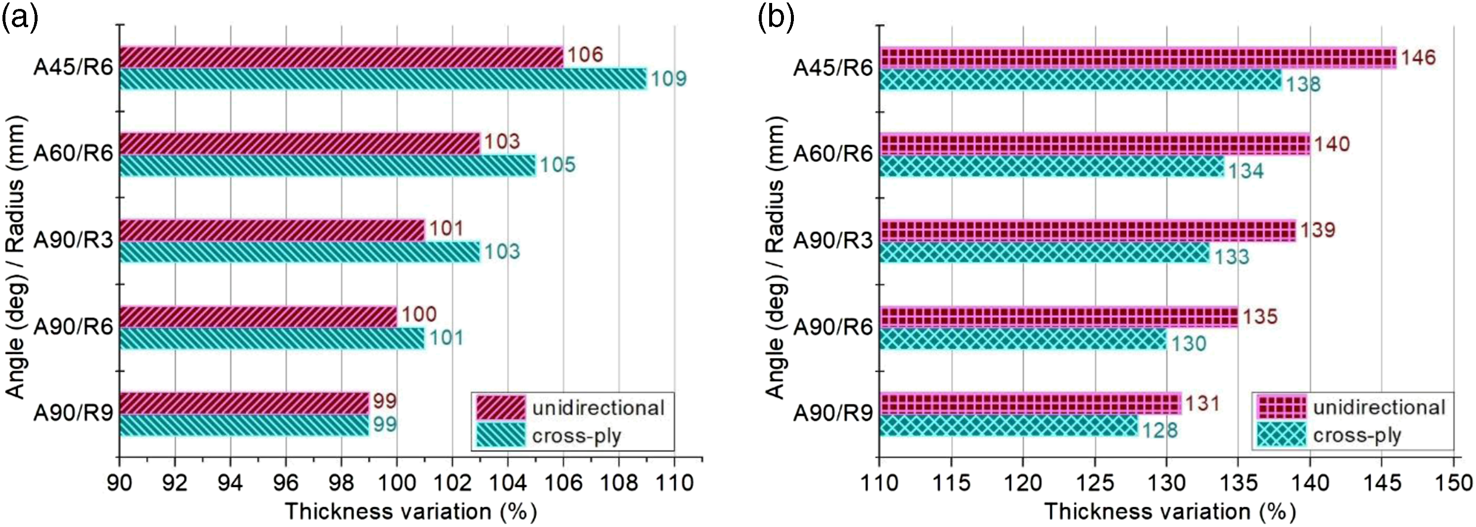
In order to make the findings evaluated in the above paragraphs more comprehensible, macro and meso-level SEM images showing the limitations of the bending process of composite sheets are presented in Figure 13. The die radius of 3 mm caused layer cracking in the outer ply and disarraying in its inner plies of the unidirectional composite sheet bent 90° under 3 MPa pressure (Figure 13(a)). When the cross-ply composite sheet was bent with a 3 mm radius, the continuous fiber broke and became short fibers and intralaminar fracture occurred in the inner plies (Figure 13(b)). In case the bending angle was 45°, the delamination and out-of-plane shearing of the cross-ply composite sheet became quite evident when the die radius was 6 mm and the pressure was 3 MPa (Figure 13(c)). In addition, the layers moved towards the inner curve, and corrugations and wrinkling occurred in the center and near the ramp (Figure 13(d)). Since the stresses and surface adhesion forces in each layer of the composite sheets were different from each other, the bending pressure of 2 MPa caused opening and sliding between the layers (Figure 13(e)). Besides, 4 MPa bending pressure caused matrix crackings and local debonding in the ramp region of the parts (Figure 13(f)). Also, some examples of bent specimens are presented Appendix. (a), (b), (c). Observation of cross sections of the composite sheets after V-bending tests (d), (e), (f). Observation of cross sections of the composite sheets after V-bending tests.
Conclusion
In this study, V-bending tests of continuous glass fiber reinforced polyamide-6 composite sheets were carried out. Thermoplastic sheets in two different structures, unidirectional and cross-ply, were used. In order to examine the geometric effects, the bending angle was altered to 45°, 60°, 90°, and the die radius was altered to 3, 6, 9 mm. To scrutinize the process effects, the bending pressure was changed to 2, 3, 4 MPa, and the dwell-time was changed to 10, 60, 120, 240 s. The results of these parameters on the spring-back angle caused by residual stresses and on the thickness distribution in the part section were shown in the graphs. After the experiments, critical regions on the parts were visualized via SEM and various deformations were compared with other findings. Obtained outcomes are given below. • It was detected that the spring-back deformation of unidirectional composite sheets is higher than that of cross-ply composite sheets. • It was determined that the residual stresses stored in the part increase as the bending angle decreases. • It was concluded that the amount of spring-back decreases with the increase of bending pressure. • It was understood that the spring-back angle increases when the tool radii are equal to or smaller than, and three times or greater than the sheet thickness. • The thickening caused by the debonding of layers of cross-ply composite sheets was higher than that of unidirectional composite sheets. • The increase in the bending angle reduced the thickening in each region of the part. • The delamination decreased as the bending pressure increased. • It was found that keeping the die radius small prevents thickening.
Footnotes
Acknowledgements
I would like to thank the Scientific and Technological Research Council of Turkey (TÜBİTAK) and the Projects and Scientific Investigation of Gazi University (GU-BAP for granting to undertake this study.
Declaration of conflicting interests
The author(s) declared no potential conflicts of interest with respect to the research, authorship, and/or publication of this article.
Funding
The author(s) received no financial support for the research, authorship, and/or publication of this article.
Some examples of bent specimens are presented below.