
Abstract
A strain-induced electrically conductive liquid metal emulsion for the programmable assembly of soft conductive composites is reported. This emulsion exhibits the shear yielding and shear thinning rheology required for direct ink writing. Examples of complex self-supported 3D printed structures with spanning features are presented to demonstrate the 3D printability of this emulsion. Stretchable liquid metal composites are fabricated by integrating this emulsion into a multi-material printing process with a 3D printable elastomer. The as-printed composites exhibit a low electrical conductivity but can be transformed into highly conductive composites by a single axial strain at low stresses (
Introduction
The widespread adoption of stretchable electronics depends on the development of easy to fabricate soft conductive composites that are highly compliant to mechanical deformations and maintain high electrical conductivity while being stretched.1,2 Liquid metal (LM) composites have become a popular choice since they take advantage of the electrical properties of metals while conserving the intrinsic stretchability and compliance of liquids.3,4 Alloys of Gallium and Indium, such as eutectic Gallium Indium (eGaIn), have been the most widely adopted LMs because of their high bulk conductivity (3.4 × 10⁶ Sm−1), 5 low melting point 15.5 C, 6 low toxicity, 7 negligible vapor pressure, 8 and ability to maintain high electrical conductivity at high strains over a large number of cycles. 9 However, directly integrating LMs into 3D stretchable devices remains a challenge.
Most techniques for integrating bulk LM into 3D devices require complex series of lithography and molding techniques.10–13 To reduce fabrication complexity, several researchers have utilized the structural stability enabled by the naturally occurring Gallium oxide (Ga2O3) shell to directly pattern bulk LMs into various geometries using additive manufacturing (i.e. 3D printing) techniques.14–17 However, the low ultimate surface stress (0.5 N m−1) 6 of the printed structures limits these bulk LM patterning approaches to simple geometries (i.e. line patterns and simple 3D stacks of droplets), and makes it difficult to integrate with other components. To address these challenges, multiple researchers have investigated different approaches of modifying the rheological properties of LM to create LM inks that are more compatible with 3D printing techniques. One approach has been to disperse solid particles into a LM matrix.18–20 However, formulations with low solids concentrations are not stiff enough to extend beyond line geometries, 19 while high solid formulations can be extruded into more complex 3D geometries, but exhibit frequent nozzle clogging. 18
An alternative approach to modifying LM rheology is to create micro and nano emulsions of LM droplets disperse in a carrier liquid.21,22 Stable dilute LM emulsions are compatible with droplet-based printing methods,21,23 while highly concentrated stable LM emulsions are compatible with direct ink writing (DIW) 3D printing.24,25 A challenge with LM emulsions is that the resulting structures exhibit low levels of electrical conductivity, owing to the low electrical conductivity associated with the materials used to stabilize the LM droplets in the carrier liquid. Rendering these emulsions electrically conductive typically requires a sintering step to displace the low conductivity materials and allow the individual droplets to coalesce into a single continuous liquid phase. To date, multiple approaches have been used to sinter LM emulsions. Laser-based sintering approaches have been employed to ablate the low conductivity materials. 26 These approaches can be used to create 2D LM patterns within LM emulsion deposits, but are limited to thin films (10 μm). Patterned LM emulsions can be sintered through high temperatures (≥900°C) in an oxygen-rich environment. 27 This results in the creation of a biphasic solid–liquid eGaIn film, with the liquid eGaIn droplets experiencing large thermal expansion, coalescing the individual LM droplets. However, the high temperature necessary for this approach requires the LM patterns to be sintered separately from the other materials, resulting in a complex device fabrication process. Mechanical sintering approaches have also been employed, where the emulsion is subjected to a stress that compresses the LM droplets leading to the rupture of the oxide skin and separating materials between individual droplets, releasing the enclosed LM and coalescing the droplets into a conductive network.21,22 However, current mechanical sintering approaches require large stresses (3 MPa 21 and 3.6 MPa 22 ) which may not be compatible with other materials that are integrated into the device.
In this work we introduce a stable aqueous LM emulsion with rheology that is compatible with DIW 3D printing. The aqueous LM emulsion is comprised of eGaIn, sodium carboxylmethyl cellulose (NaCMC), and water, and can be quickly synthesized using a shear mixer. During mixing, the eGaIn is sheared into micrometer-sized droplets and dispersed within the continuous aqueous NaCMC solution phase. The resulting emulsion has a stiffness and yield stress that are large enough so that complex, self-supported 3D structures with overhangs can be readily manufactured. Unlike previous emulsion formulations, our emulsion requires an order of magnitude smaller stresses (
Experimental methods
Materials
The LM emulsion is comprised of eGaIn (5N Plus), NaCMC (MW ≈ 250,000) (Acros Organics) and deionizied (DI) water (MilliQ). First, an initial bulk aqueous solution is made by mixing 5% NaCMC into deionizied water using a dual asymmetric centrifugal mixer (SpeedMixer model DAC 150.1 FVZ-K, FlackTek) at 3500 r/min in 5 min intervals until a homogeneous solution was obtained. Once homogeneity is obtained, 0.18 g of the bulk NaCMC solution is added to 0.06 g of DI water for further dilution, followed by an additional mixing step (3500 r/min, 2 min), resulting in a 3.75% w/w aqueous NaCMC solution. The LM emulsion is then created by adding 4.81 g of eGaIn to the aqueous NaCMC solution, followed by another shear mixing sequence (1750 r/min, 3 min; 3500 r/min, 15 min). The final composition of the resulting emulsion is 76.4% v/v eGaIn, 23% v/v water, and 0.6% v/v NaCMC. The emulsion was then loaded into a 3cc syringe and prepared for 3D printing.
The body ink (BI) used to 3D print the substrates for the dogbones and the LED device was made of the two-part silicone Ecoflex 00-30 (Smooth-On) and fumed silica as a rheology modifier. Part A and part B were separately mixed with fumed silica as the mixing process generates heat, which affects the pot life of the polymeric mixture. First, part B was shear-mixed with 2% w/w of SloJo (Smooth On) for 1 min at 3500 r/min to increase the elastomer pot life. Then, 7% w/w fumed silica (Aerosil 150, Evonik) was added to part B as a rheology modifier, and shear-mixed for 4 min at 3500 r/min (in 1 min increments). Similarly, part A was shear-mixed with 7% w/w fumed silica for 4 min at 3500 r/min (in 1 min increments). Part A and part B were then mixed together for 1 min at 1750 r/min. The resulting elastomer was then loaded into a 10cc syringe, centrifuged at 4000 r/min for 30s and prepared for 3D printing. The elastomer used to package the devices was made of neat liquid Ecoflex 00-30 (Smooth-On) by shear-mixing equal masses of part A and part B together for 1 min at 1750 r/min. All materials were processed under ambient conditions (Temperature: 23.8 C and Relative humidity: 44.4%), unless otherwise stated.
Rheology characterization
The aqueous NaCMC solution (3.75% w/w) was characterized at T = 25°C using a hybrid rheometer (TA Instruments Discovery HR-1 model) with a cone plate geometry (40 mm plate diameter, 1°, 28 μm working gap), as it guarantees a uniform shear rate across the sample. 28 The cone plate geometry was covered by a closed chamber accessory (TA Instruments) to reduce the effect of evaporation during experiment. The emulsion was also characterized under the same temperature, but using a parallel plate geometry (20 mm plate diameter, 1 mm working gap) covered by a closed chamber accessory. The working gap between the parallel plates is 10 times the size of the maximum particle size observed in the emulsion, as this is often recommended when using parallel plates geometry. 28 To ensure a high humidity environment when characterizing the emulsion, 10 droplet of water were placed around the sample, inside the closed chamber. Before each test, both samples were pre-sheared at 1 s−1 for 5 minutes followed by a 1 min equilibration step by letting it rest. To obtain the storage and loss modulus (G′, G″, respectively) for the NaCMC solution and the emulsion, the instrument was set to operate in amplitude sweep mode, where the angular frequency was set to 1.0 rad/s. The torque applied was logarithmically swept from 1.0 × 10⁻¹ μN·m to 5.0 × 10³ μN·m, with 20 points collected per decade. To obtain apparent viscosity, the instrument was set in flow sweep mode. The applied shear rates for each sample were logarithmically swept from 1.0 × 10⁻² s−1 to 1.0 × 10³ s−1 with 20 points collected per decade. For the emulsion, the shear rate sweep was conducted in the reverse order (i.e., from high to low: 1.0 × 10³ s−1 to 1.0 × 10⁻² s−1) to avoid the short-term transients during the viscoelastic solid to fluid transition, 29 which could lead to noise at low shear rates.
Droplet size
The LM droplet size distribution was done using an image of the emulsion printed on a glass slide. The image was taken using a camera (UI-3590CP Rev. 2, IDS) connected to a miniature microscope lens system (InfiniTube FM-100, Infinity) and a 18 mm/2.00x lens (PL-Series, Infinity). To obtain the droplet size distribution, the raw image was uploaded to ImageJ, 30 converted to black and white, and segmented to get a clear definition of each droplet in the emulsion. The data was then exported from ImageJ and analyzed using custom MATLAB code.
Multimaterial 3D printing
The inks were 3D printed using a custom gantry system (Aerotech). Both the emulsion ink and the substrate ink syringes were equipped with gauge 27 (ID = 200 μm) smooth-flow nozzle (Nordson, EFD) for 3D printing. Ink extrusion was performed using a pressure controller (Ultimus V High Precision Dispenser, Nordson, EFD). The emulsion was extruded at a pressure of 13 psi, and the BI was extruded at a pressure of 74 psi using a high pressure dispensing tool (HP10cc, Nordson, EFD). The print speed used for both inks was 40 mm/s. The custom print-paths used for multimaterial printing were written using open-source python libraries (Mecode 31 ), and loaded to the Aerotech controller (A3200, Aerotech) for print execution. For easy handling and removal, all devices and samples were printed on top of a Teflon-coated steel plate.
Mechanical characterization
Mechanical tensile testing was performed using an uniaxial testing setup (Model 6800, Instron) on dogbones made following ASTM D638-14 standard. Tensile testing was done on 12 dogbones to characterize the mechanical properties of the different materials used for 3D printing the conductive composites. Of these 12 dogbones, three are made of the printed BI, emulsion features with wires (EW) and neat packaging material (NP) (BI + EW + NP). Three are made completely of the BI. Another three are made of both the BI and NP (BI + NP). The remaining three are made of the NP, made using a mold. The data was analyzed using custom MATLAB code.
Electromechanical characterization
The dogbones were fabricated by first printing a base with walls using the BI. The base with walls was subsequently cured at 70 C for 30 min using an oven (HeraTherm, Thermo Scientific). The emulsion feature was then printed on top of the cured base to avoid perforations of the base when manually adding wires to the emulsion. The nominal length of the embedded emulsion feature was 14 mm, with a width of 1 mm and a thickness of 0.2 mm. After printing the emulsion, the 3D profile of the printed emulsion feature was measured with a laser profiler (LJ-X8080, Keysight). Two sensing wires were then manually added into the emulsion. Before adding the two wires, their electrical resistance was measured using a source meter (2401A, Keithley) with a four-point probe (5806, Keithley). Directly following the manual addition of sensing wires, the dogbones are then packaged and cured at room temperature for at least 4 h.
Electromechanical characterization consisted of recording electrical resistance data of dogbones as they were cyclically stretched. Dogbones were characterized at strains corresponding to 50%, 100%, 200%, 300% and 400% of the nominal printed emulsion feature length. Three dogbones were tested for each strain level. The stretching set-up consisted on two modified clamps (Three-way clamps, Bossey), with one mounted on the motion system bed, and one mounted on an independently controlled z-axis. Electrical resistance was measured using a source meter (2401A, Keithley) with a four-point probe (5806, Keithley). The electrical resistance from the wires was subtracted from the measured electrical resistance of the emulsion to obtain the resistance of the emulsion features. A custom python script was used to control the motion of a linear stage (ATS150, Aerotech), where the speed, travel distance, and number of cycles were used as inputs. An additional custom python script was used to collect and synchronize the linear stage position with the measured electrical resistance. The dogbones were cyclically stretched and relaxed at a rate of 15 mm/s for each of the five strains tested. The data collected was analyzed using custom MATLAB (Mathworks) code.
LED device fabrication
An LED array was fabricated using multimaterial 3D printing, which consisted of 20 surface mount LEDs (Red, 0603, Kingbright) connected in parallel. The LED device was fabricated by first printing a substrate layer with walls made of the BI, which was immediately cured at 70 C for 30 min using an oven. This was followed by printing the conductive traces with the emulsion ink. Droplets of the BI were then printed in the LEDs final location, which serve to adhere the LEDs to the substrate. The LEDs were then manually placed on top of the adhesive droplets, bridging the power and ground traces. The device was subsequently packaged, and defoamed for 1 h under vacuum to remove air bubbles. Finally, the device was cured at room temperature.
Results and discussion
Figure 1 shows the 3D printed LM emulsion, with Figure 1(a) showing a schematic of the 3D printing process. An optical microscope image of a 3D printed emulsion sample is shown in Figure 1(b), with the emulsion composition illustrated in Figure 1(c). The droplet size distribution of the optical microscope image is shown in Figure 1(d). The average diameter of the LM droplets was found to be 21μm ± 2 μm (95% confidence interval), obtained by fitting a log-normal distribution to droplet size distribution data. A log-normal distribution fit is used as it is known to accurately model right-skewed data.
32
Right-skewed data is common in attrition processes to produce LM droplets, as it has been previously reported on other LM emulsions.25,33,34 The minimum droplet diameter observed was 7 μm, and the maximum droplet diameter was 120 μm. Although the maximum diameter is on the same order as the nozzle inner diameter (200 μm), the LM droplets do not clog the nozzle, likely due to the liquid nature and high compliance of the droplets. 3D printed LM emulsion ink. (a) Schematic showing the 3D printing of a continuous filament of LM emulsion. (b) Optical microscope image of the 3D printed emulsion. Scale bar is 100 μm. (c) Schematic of the emulsion composition. (d) Droplet size distribution of the optical microscope image in b).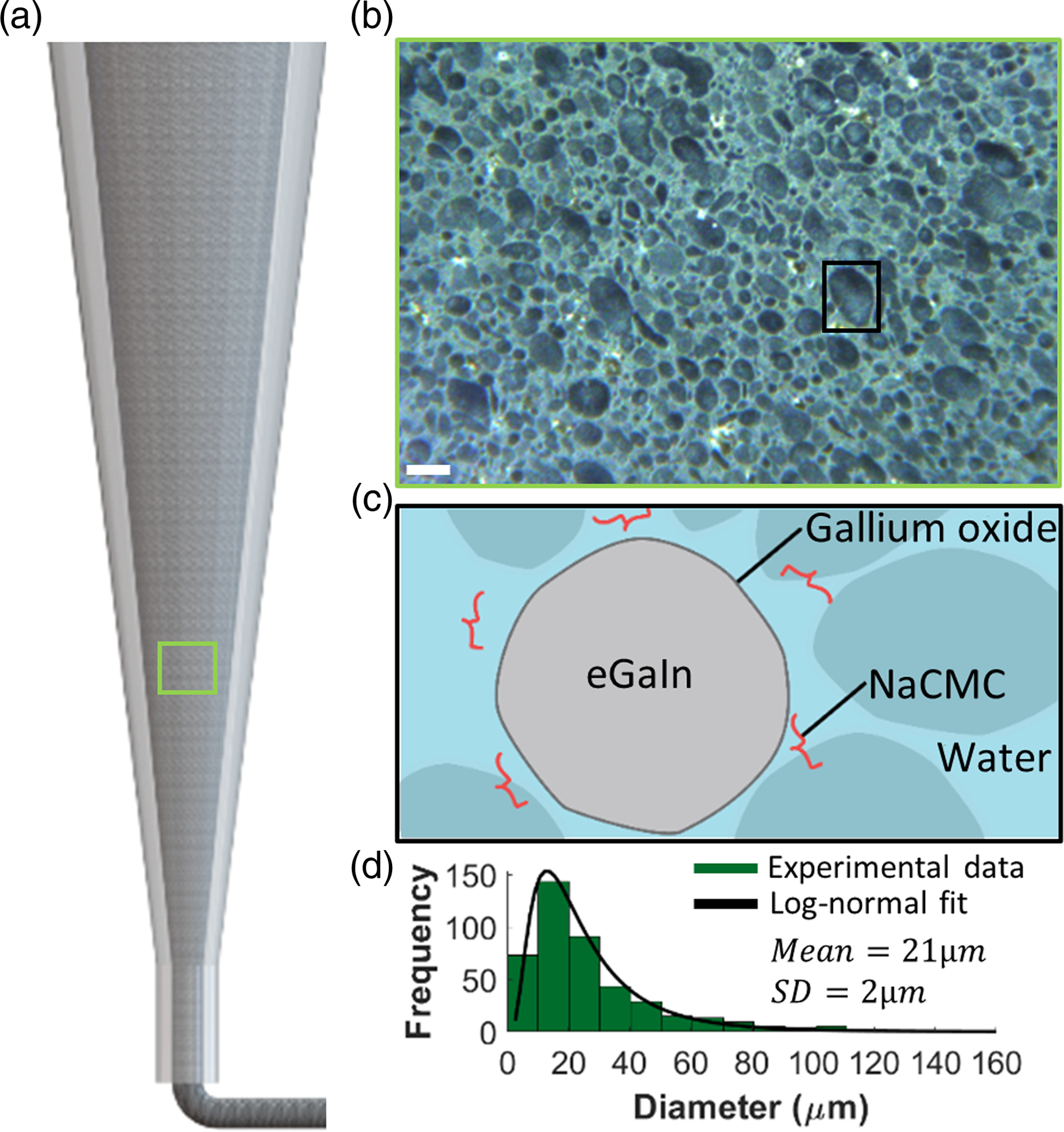
Rheology
Figure 2(a) shows rheological data collected on the aqueous NaCMC solution (no eGaIn) and the NaCMC-based LM emulsion. Oscillatory data collected on the aqueous NaCMC solution and the emulsion are presented in Figure 2(a).i, which show the storage modulus (G′) and loss modulus (G″) in response to shear stress. The aqueous NaCMC solution shows a higher loss modulus (G″) than storage modulus (G′) at the tested shear stress range, indicating that the NaCMC solution exhibits no yield stress and behaves more like a fluid than a solid. Given the fluid-like behavior and lack of a yield stress, the NaCMC solution alone cannot be used for 3D printing solid-like filaments. On the other hand, the emulsion shows an elastic behavior as its storage modulus (G′) remains higher than the loss modulus (G″) at low shear stresses, until shear yielding occurs and its behavior transitions to predominantly fluid-like at higher shear stresses. The elastic behavior of the LM emulsion at low shear stresses suggests that it can be used for 3D printing solid-like filaments capable of retaining their shape after nozzle extrusion. This observed behavior with our 76.4% v/v eGaIn emulsion is consistent with other observations on dense emulsions,35,36 who demonstrate that emulsions with a dispersed phase volume content above random close packing (i.e., 64% v/v
37
) behave like solids due to the increased inter-droplet energy from droplet deformation as a result of being compressed. Ink rheology and 3D printed structures. (a) Emulsion (gray) and NaCMC solution (turquoise) rheology data. (i) Storage modulus G (solid line) and loss modulus G (dashed line) as a function of shear stress. (ii) Apparent viscosity as a function of shear rate. The black dotted line denotes the fit of the shear rate data to the Herschel-Bulkley model. The black crosses shows the shear rate data fit to the cross model. (b) Layered 3D printed structure. (i) Schematic of the printing process for the self-standing structures. (ii) Shows self-standing 3D structures with overhangs that is mechanically stable. Scale bar is 2 mm.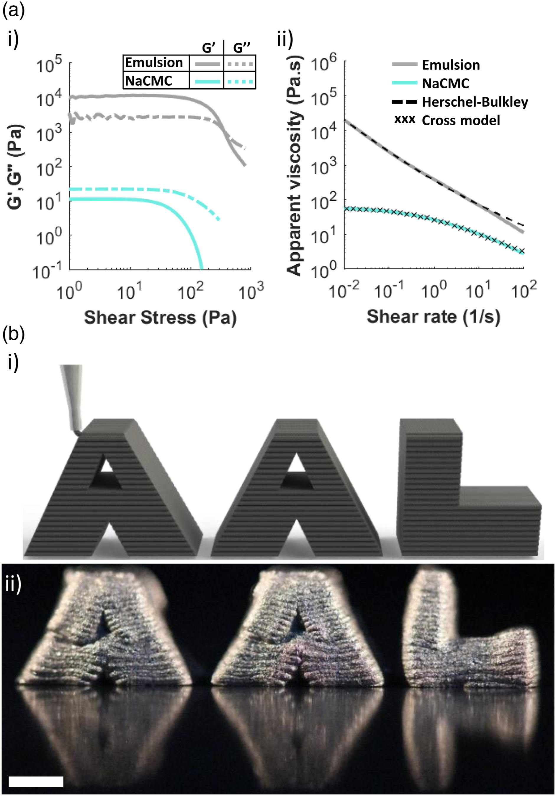
Figure 2(a).ii shows data from flow sweep experiments where both the aqueous NaCMC solution and the LM emulsion exhibit shear thinning behavior, as viscosity decreases with increasing shear rate. The NaCMC solution shows a shear-thinning behavior, which is consistent with work by Benchabane and Bekkour,
38
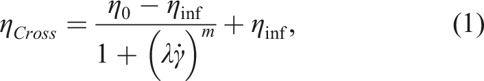
who report flow data for solutions with NaCMC concentrations ranging from 0.2–5.0 w%. The particular shear-thinning behavior of the aqueous NaCMC solution can be represented by the cross model
39
On the other hand, once eGaIn is emulsified within the aqueous NaCMC solution, the emulsion presents a log-linear shear-thinning behavior with no Newtonian plateau, indicating the formation of an internal structure and presence of yield stress. 40 This is consistent with the findings shown in Figure 2(a).i, where shear yielding is observed. The emulsion also shows a three order of magnitude increase in viscosity at low shear rates, when compared to the aqueous NaCMC solution. This increase in viscosity is consistent with previous work on liquid metal emulsions which found that the emulsion viscosity increases with higher volume loading of liquid metal.41,40
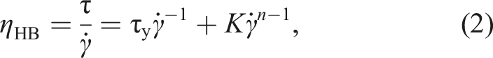
To further characterize the printability of the emulsion, calculations of emulsion yield stress are performed. The yield stress for the emulsion is determined by fitting the Hershel-Bulkley model of apparent viscosity versus shear rate data, as shown in Figure 2(a).ii. The Herschel-Bulkley model for apparent viscosity versus shear rate data is described by
42
The utility of the emulsion was further assessed by evaluating the spanning distances of 3D printed structures, as detailed by Smay et al.
43
This method calculates the minimum storage modulus needed to achieve a filament capable of spanning distances. The minimum storage modulus is given by
43
Electromechanical characterization
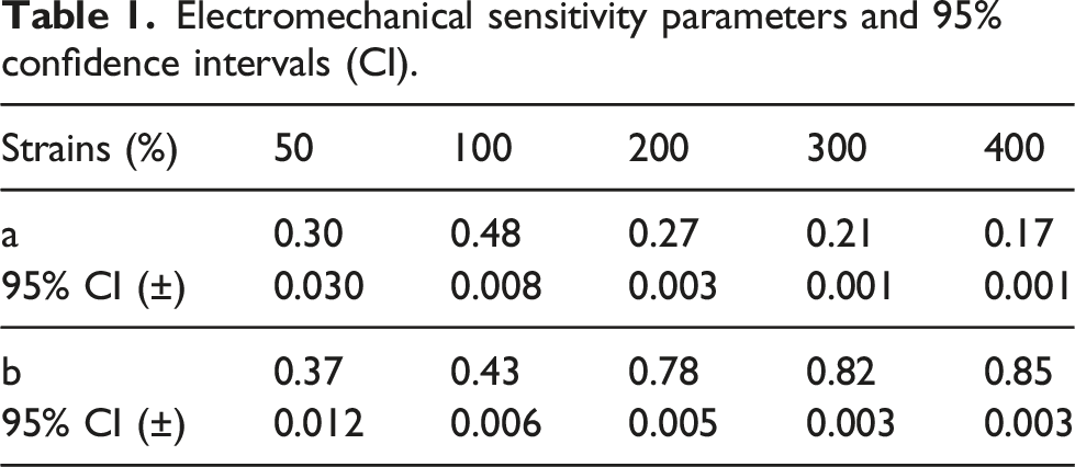
Figure 3(a) i-iii shows the multimaterial printing process for the dogbones subjected to electromechanical characterization. The electromechanical characterization was conducted using the custom set-up shown in Figure 3(b) i-ii, in where dogbones were cyclically stretched at different strain levels. 3D printing and electromechanical characterization of the conductive composites. (a) Multimaterial 3D printing schematic of an ink-elastomer composite dogbone. First, (i) The base and walls of the dogbone are printed using the BI. Then, (ii) The emulsion is printed on top of the cured base layer. Lastly, (iii) two wires are added to the printed trace, and the dogbone is packaged with Ecoflex 00-30. (b) Schematic of electromechanical and mechanical characterization. (i) Schematic representing the stretching setup for electromechanical characterization. (ii) Images of a dogbone being stretched from zero to four times its original length. Vertical scale bars are 10 mm. (iii) Engineering stress as a function of engineering strain obtained from the mechanical characterization of dogbones made with: body ink (BI), body ink with packaging material and the emulsion embedded with wires (BI + EW + NP), body ink and neat packaging material (BI + NP), and neat packaging material (NP). (c) Conductivity of the LM emulsion ink as a function of cycle number at different strains. (d) Relative resistance change as a function of the number of cycles. The blue box shows a magnified view of three stretching cycles. (e) Relative resistance change as a function of strain for all cycles, and Pouillet’s law based on a bulk conductor. (f) Electromechanical sensitivity (solid lines) and 95% confidence intervals (shaded regions) of the sensitivity of relative resistance change as a function of strain for all samples.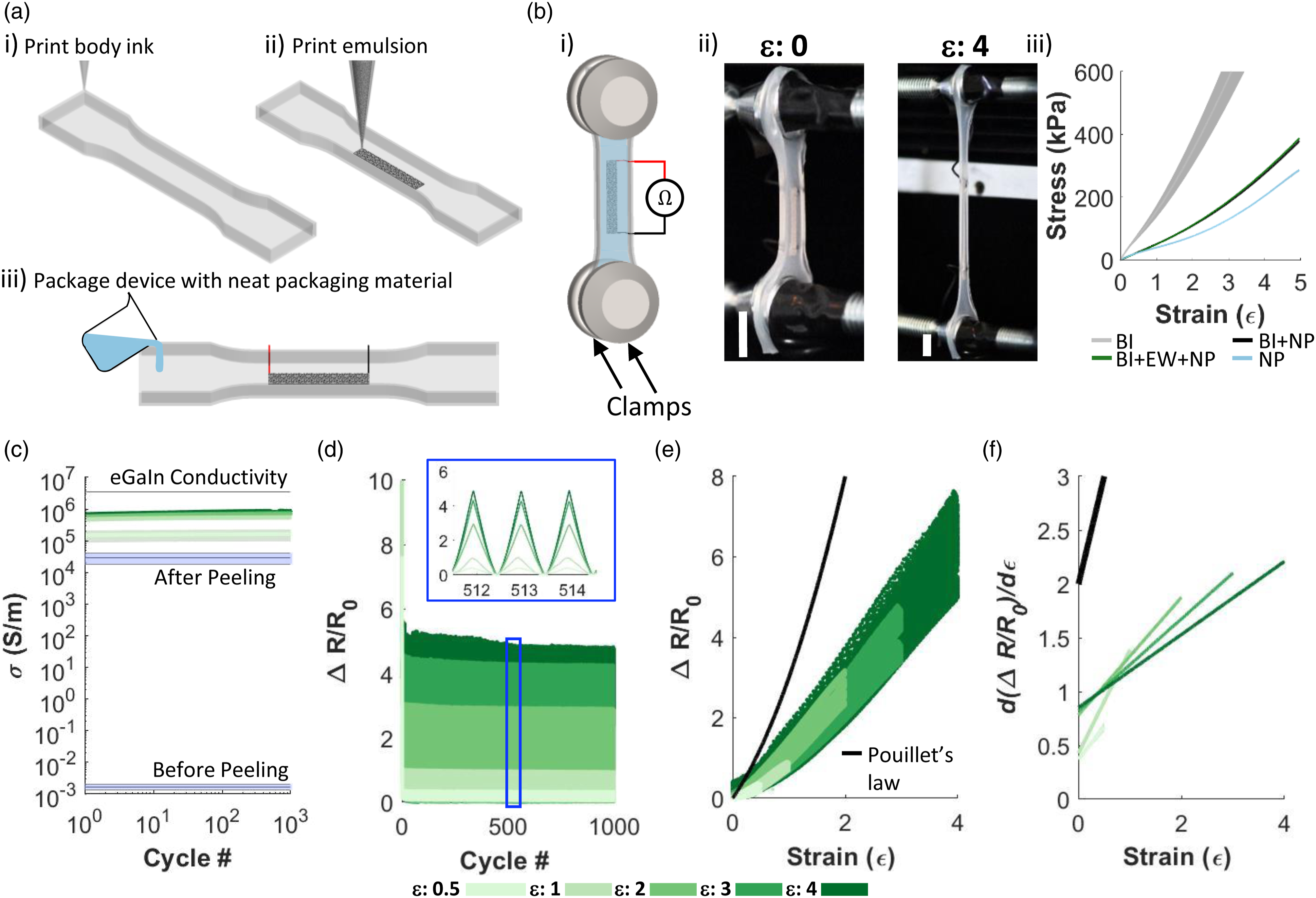
Figure 3(b) iii shows the engineering stress as a function of engineering strain of 12 dogbones, three made of the BI, three made of BI + EW + NP, three made of the BI + NP, and three made of NP. The dark lines denote the mean, and the shaded region denotes the standard deviation of the data. There are no notable differences between composites of the body ink (BI) with the emulsion with wires (EW) and neat packaging (NP) (BI + EW + NP) and those only comprised of the BI and NP (BI + NP). These findings support previous work, which reports that the inclusion of LM droplets allows the host polymer to preserve its mechanical properties. 3 On the other hand, as seen from Figure 3(b).iii, dogbones made of only the BI show a more elastic behavior with higher stiffness, while dogbones made of only the NP exhibit a lower stiffness and a more pronounced hyperelastic region at higher strains. This agrees with previous work that added different loadings of fume silica to polymers and observed an increase in stiffness with increased concentrations of fumed silica. 46 Although there are differences between the mechanical properties of BI and NP, this did not affect the electromechanical tests as no delamination was seen during any of the tests of BI + EW + NP, which indicates a strong adhesion between the packaging layer and the cured base and walls of the devices.
To explore the electromechanical response of the dogbones with the emulsion features, samples were strained uniaxially to fracture the NACMC and Ga2O3 that separate individual droplets, thereby forming highly conductive coalesced networks. Figure 3(c) shows the mean conductivity (dark lines) and standard deviation (SD) of dogbones tested at different strain levels, as well as their mean conductivity before and after peeling them off the Teflon substrate. The mean conductivity was calculated using the relaxed resistance (resistance after each cycle) and the cross-sectional area of the dogbones used in each group. Dogbones are not conductive right after packaging and curing, as seen in the lower purple shaded region on Figure 3(c). However, they exhibit a jump in conductivity when peeled from the substrate, with a mean conductivity of 2.87 × 10⁴ S·m−1 and an SD of ±1.10 × 10⁴ S·m−1, as seen in the top purple shaded region on Figure 3(c). This increase in conductivity is in agreement with previous work that achieves conductivity upon peeling.25,40 However, the highest after-peeling conductivity is still around two orders of magnitude lower than that of bulk eGaIn, indicating a coalesced conductive network composed of a small fraction of the eGaIn droplets. It is important to note that although the samples were carefully peeled from the substrate, their conductivity is highly dependent on the amount of strain induced on the dogbones during the peeling process. This dependence on strain can explain the high standard SD for the dogbones after being removed from the substrate.
As shown in Figure 3(c), the mean conductivity for samples activated at a strain of 50% was 1.61 × 10⁵ S·m−1, with an SD of ±1.43 × 10³ S·m−1. For samples activated at 100%, their mean conductivity was 5.53 × 10⁵ S·m−1 ± 7.69 × 10³ S·m−1. Samples activated at 200% had a mean conductivity of 7.04 × 10⁵ S·m−1 ± 1.30 × 10⁴ S·m−1. The mean conductivity for samples activated at 300% was 7.50 × 10⁵ S·m−1 ± 2.15 × 10⁴ S·m−1. Lastly, samples activated at 400% had a mean conductivity of 8.61 × 10⁵ S·m−1 ± 4.78 × 10⁴ S·m−1. These results show that conductivity increases with higher strains, with a sharp increase after only 50% strain, and significant increase until a strain of 400%. Although straining the samples at 400% shows the highest conductivity, it also has the highest variation (SD). The observed increase in SD with increased strain could be caused by the deformation of the interface between the packaging material and the wires, which we observed completely separates for strains above 400%. Through this approach we achieve eGaIn composites exhibiting conductivities of up to 25% of the bulk LM, indicating a significant increase in the fraction of coalesced eGaIn droplets. Further increase in the fraction of coalesced eGaIn droplets may be inhibited by Ecoflex 00-30 infiltrating through part of the printed emulsion, thereby preventing activation of eGaIn droplets at the elastomer/emulsion interface. The maximum zero-strain conductivity achieved in this work is more than three times that of previous work on LM emulsions that mechanically sintered drop casted samples via axial strain. 47 Revisiting the mechanical data for the dogbones in Figure 3(b).iii, the stress needed to coalesce the embedded emulsion can be as low as 25.21 kPa for 50% strain, 50.3 kPa for 100% strain, 109.9 kPa for 200% strain, 187.9 kPa for 300% strain, and 282.4 kPa for 400% strain. This is at least an order smaller than previous work on mechanically sintered LM emulsions.21,22 Smaller activation stresses would allow for a larger range of compatible polymers, and activation protocols that do not risk mechanical failure.
As shown in Figure 3(c), the conductivity of all samples reach a steady state after just one cycle for all applied strains. The packaged emulsion stability is demonstrated by its low variation of less than 6% SD for all strains. The packaged emulsion stability is further demonstrated in Figure 3(d), which shows the relative change in resistance (relative resistance divided by the zero-strain resistance, ΔR/R0) as a function of cycle number, for all strain magnitudes tested. Similar to the conductivity after the first cycle, ΔR/R0 has a sharp decrease after the first cycle for all strains tested, and remains consistent showing a repeatable behavior throughout 1000 cycles. The blue box insert on Figure 3(d) shows a magnified view of three cycles after approximately 500 cycles. From this insert it can be seen that the data is consistent from cycle to cycle, and as expected, the ΔR/R0 is dependent on the applied strain.
Electromechanical sensitivity parameters and 95% confidence intervals (CI).
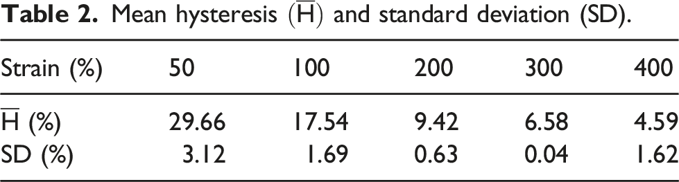
Mean hysteresis
To showcase the utility of the emulsion ink, a 3D printed stretchable array of LED spelling our lab initials “AAL” was fabricated, as shown in Figure 4(a).i-vi. To activate the LED device, it was mounted on linear axis stage for stretching, and connected to a power source (E36233 A, Keysight). Once connected, the device was stretched until it became permanently conductive and all LED’s light up. Some LEDs started to light up at a strain of 80%, but only became fully activated at a strain of approximately 110%, where all LEDs light up. Once activated, the LED device remains conductive at both its relaxed state (Figure 4(b).i), and when stretched to 200% (Figure 4(b).ii). Stretchable array of LED’s. (a) Fabrication process of the LED device using the LM emulsion ink for the soft electrical wiring. (i) First the base and walls are printed with the BI. (ii) Next, the power and ground traces are then printed on top of the cured base layer. (iii) A droplet of adhesive (i.e., BI) is then printed on top of the base layer, between the traces. (iv) The LED’s are manually placed on top of each adhesive droplet using tweezers, and wires are then placed on the ground and power ends. (v) The device is subsequently packaged with Ecoflex 00-30. (vi) Lastly, the Ecoflex 00-30 is degassed before it cures. (b) LED “AAL” array at (i) its original length, and (ii) after stretching to 200% of its original length. Scale bar is 10 mm.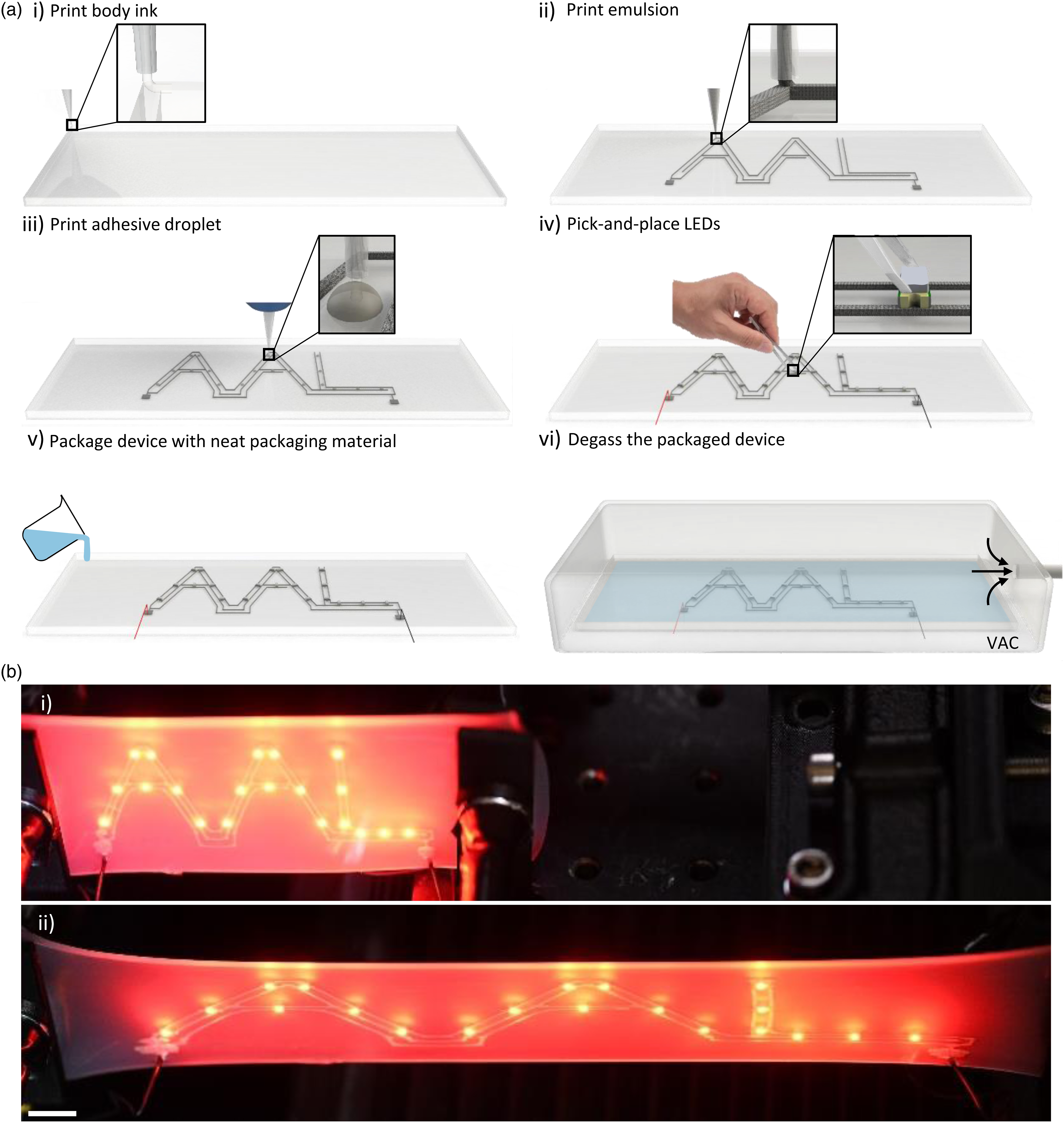
Conclusion
The ternary liquid metal emulsion presented in this work has a rheology that is compatible with 3D DIW, and shows high strain-induced conductivity at low stresses. Once synthesized, the emulsion displays a rheology capable of 3D printing self-supported complex 3D structures with overhangs. Upon packaging, the emulsion was shown to be electrically conductive by axial strains, with a maximum conductivity and activation stress that is three times larger and an order of magnitude smaller, respectively, compared to previous work. The emulsion ink also exhibits outstanding electrical stability, with consistent conductivity after just one cycle, and low variation (
Footnotes
Acknowledgements
The authors gratefully acknowledge support from the AFOSR Young Investigator Award (FA9550-20-1-0365; J.W.B., R.E.S.C.) and the National Science Foundation CAREER Award (CMMI-2047683; J.W.B., S. F. Zopf). The authors thank J. M. Morales Ferrer for his help on mechanical tensile data acquisition, and insights on experimental setup and data analysis. Lastly, the authors thank Professor Keith Brown and his lab for access to their rheometer, especially A. Rendos for her help on the experimental setup for rheology.
Declaration of conflicting interests
The author(s) declared no potential conflicts of interest with respect to the research, authorship, and/or publication of this article.
Funding
The author(s) disclosed receipt of the following financial support for the research, authorship, and/or publication of this article: This work was supported by the Division of Civil, Mechanical and Manufacturing Innovation (CMMI-2047683) and Air Force Office of Scientific Research (FA9550-20-1-0365).