






Abstract
A novel design and method of manufacture of laterally corrugated composite tube is proposed. One of the main issues with studying such corrugated composite tubes has been taking out the mandril from the composite specimens, leading to very little, if any, experimental research into this subject. Therefore, as the main novelty of this paper, a multi-step process has been thoroughly explained to overcome these manufacturing challenges, i.e., the use of ABS corrugated mandrels, silicone molds, wax mandrels, filament winding, and finally heating the wax mandrel to melt. At the end of this process, the lateral corrugated composite tube is obtained. There are two different types of specimens: conical corrugated composite tube and cylindrical corrugated composite tube. From each category, two specimens are tested, whose crashworthiness results are then compared with one another to see which design offers better energy absorption capacity. Subsequently, using the experimental data, a finite element model is developed and validated to numerically look into the effect of number of corrugations on the crashworthiness of the structures. To do so, the specific energy absorption (SEA), peak force, mean force, and crushing force efficiency (CFE) of each model have been compared with one another. It is understood from both experiments and numerical study that the conical composite tubes offer better crashworthiness as they can absorb more energy and maintain a higher mean force than the cylindrical ones. For instance, in the experiments, it was observed the conical corrugated composite tube had an SEA of 12.37 kJ/kg, while this value for cylindrical one was 8.38 kJ/kg. Moreover, with an increase in the number of corrugations within a set length for the tube, the energy absorption capacity of the structure can be increased. To provide a better understanding of the observation, with an increase in the number of corrugations from 12 to 18, SEA increased from 9.21 to 12.43 kJ/kg in the cylindrical models, and from 10.80 to 13.01 kJ/kg in conical ones.
Keywords
• A novel manufacturing method for corrugated thin-walled composite tube was proposed. • Crashworthiness of the corrugated composite tubes was studied experimentally. • Conical corrugated tubes showed higher energy absorption than cylindrical ones. • A parametric FEA was conducted on the number of corrugations. • Higher number of corrugations resulted in better crashworthiness.Highlights
Introduction
Transportation has been continuously gaining more attention and becoming a salient part of every individual’s life. Over the years, energy absorbers have been widely used by many researchers and engineers in transportation systems, for instance in vehicles, and other priority systems, like blast protection structures, in order to convert the kinematic energy caused by crashes and impacts and dissipate it through plastic deformation.1–3 The majority of these energy-absorbing structures are designed as thin-walled structures with diverse geometries, dimensions, and choice of material, due to their high capacity of crashworthiness and high strength-to-weight ratio. Tubes with octagonal cross-sections were studied by Mamalis et al. 4 for the first time. Various shapes were investigated by Tarlochan et al. 5 concluding that circular and conical tubes have higher capacity for energy absorption. Azimi and Asgari looked into the energy absorption of meta-model of miniature frusta, showing its superiority in comparison with cylinders of the same size. 6 In addition to the cross-section of the tubes, many studies have already been conducted, which proved that corrugations can beneficially impact the amount of energy absorbed in both steel and composite structures.7–13 The primary benefit of this geometrical characteristic is to enhance the uniformity of the force-displacement results obtained from axial crushing of the structures, as well as increasing the predictability and control of and the failure in each corrugation. Moreover, the energy absorption capacity of the whole structure is improved. Ahmadi and Asgari looked into corrugated conical tubes, showing that they have higher energy absorption than straight tubes. 14 It was also revealed that the higher the numbers of corrugations are, the more capacity there is for absorbing energy. 15
Composite structures have proven to have high energy absorption and strength despite their low density, which is a favorable feature for energy absorbers. Mamalis et al. 16 were among the first researchers who thoroughly investigated the energy absorption capacity of composite tubes. They revealed that circular and conical composite tubes have better crashworthiness than other tubes. They also concluded that there are three dominant failure modes, among which the progressive stable crushing mode results in a more beneficial mean force. 17 Hanefi et al. 18 was one of the pioneers of exploiting reinforced metal-composite walls as energy absorbers. Moreover, energy absorbers with different fiber reinforcements were also studied in. 19 The effect of corrugation in the composite structures on the mode of failure and their compressive and tensile strength was also investigated.20,21 The corrugations were in the radial direction and the composite corrugated tubes showed outstanding results in energy absorption in axial loading. Furthermore, flat-topped conical structures composed of textile composite were studied by Xue et al. 22 which were verified by theoretical and experimental solutions. In some other research,23–25 the energy absorption of different geometries of E-glass/polyester composite structures was studied to compare these different geometries and determine the structures with optimal energy absorption. Additionally, the response of composite energy absorbers under both normal and off-axis loads has been reported in a number of investigations.26–32 In one of the studies, corrugated cylinders were numerically investigated by Mahbod and Asgari, showing better crashworthiness than straight tubes. 33 Sadighi et al. 34 researched into the energy absorption capacity of foam-filled bi-tubular conical-cylindrical tubes, which displayed much higher energy absorption capacity than their bi-tubular straight tubes. Alkhatib et al. 35 looked into the crushing response of CFPR and KFRP composite tubes, which were filament-wound on ABS wedge-like corrugated mandrels and failure modes were investigated. Additionally, in a number of studies, hybrid metal-composite corrugated tubes were investigated. Eyvazian et al. 36 conducted experimental study on corrugated metal-composite energy absorbers under axial loading. Furthermore, Sadighi et al. 37 conducted a parametric study into two distinct corrugation types in both aluminum and composite-aluminum cylindrical tubes, concluding that circular corrugations, in comparison with wedge-like corrugations, can both decrease the maximum peak load as well as render a more uniform force-displacement result after this initial peak load.
As mentioned above, several investigations were done into the crashworthiness of composite energy absorbers. Nonetheless, they were either into tubes with simple geometries without any corrugations,38,39 numerical studies on corrugated composite energy absorbers validated with limited experimental data from straight tubes, 33 or even corrugated composite tubes were tested with the mandrels as they were explained to be impossible to detach. 35 However, to the best of authors’ knowledge, there have been very few, if any, experimental studies on the crashworthiness of composite tubes with circular corrugations on the lateral surface. Manufacturing complexities of such tubes had caused a hindrance and there was lack of enough experimental data on the energy absorption capacity of such tubes. However, in this paper, two different conical and cylindrical composite tubes with circular corrugations have been manufactured through a novel procedure, which has been explained in detail. Subsequently, two specimens from each category have been crushed under quasi-static conditions. The reason for performing the investigation under this condition is the fact that numerous studies have used the same loading condition in their experiments.23,40–43 Afterwards, a set of corrugated conical and cylindrical composite tubes have been modeled in LS-DYNA, which have been validated using the force-displacement results obtained from the experiments. Then a parametric investigation has been performed into the number of corrugations in these corrugated cylindrical and conical composite tubes, and their crashworthiness has been compared with one another.
Experimental investigations
Although energy absorbers are very likely to be subjected to dynamic loading conditions, in this study, the corrugated tubes will undergo quasi-static crushing in order to have their crashworthiness parameters analyzed. The reason for doing so is that the same chief results are observed as they are under low-velocity impacts. Many studies have also looked into the energy absorption of the tubes under quasi-static conditions.42–46 Moreover, Chiu et al. 47 conducted a comprehensive study on carbon fiber-reinforced energy absorbers under different strain rates. It was found that the energy absorption of composite structures is strain rate independent up to the strain rate of 100 s−1. This observation was attributed to high fiber content in such tubes and the fact that fracture energy release rate of carbon fibers is higher than and dominant to that of the matrix. In our study, we also believe that even though damage phenomenon and energy absorption could be related to strain rate in general, as all of the tubes and models are carbon fiber-reinforced and that they are all crushed under the same loading condition, similar to the studies above, the results and finding are considered to be independent from the strain rate.
Construction of test specimens
The specimens which will be analyzed in this study are corrugated conical and cylindrical carbon reinforced composite tubes. The main challenge in the way of doing experimental studies on corrugated composite tubes was finding a way to set up a corrugated mandrel around which fibers will be wound, and then taking out the mandrel to test the corrugated composite tubes. As far as our knowledge goes, no studies have proposed a method to overcome this challenge. In this paper, the conical and cylindrical mandrels were constructed using ABS plastic (Acrylonitrile Butadiene Styrene) via 3D printing. The schematic of the mandrels has been depicted in Figure 1. Both mandrels have 16 corrugations, and the corrugations have the curvature radius of 10 The schematic of the (a) conical (b) cylindrical corrugated ABS mandrels with 16 corrugations.
Nevertheless, one of the challenges of manufacturing fiber composite specimens through filament winding or even manually laying up the composite layers would be how to take out the mandrels from the corrugated tube. This challenge has clearly been an issue in the previous studies. In one of these studies, for instance, no solution was found and the crushing test was performed on these tubes containing mandrels at the same time.
35
However, one of the novelties of this study was to find a process through which corrugated composite tubes could be manufactured. Therefore, in the next step, using the ABS mandrels, silicon molds are obtained (Figure 2(c)). Subsequently, using these silicone molds, mandrels could be made with wax. To do so, the wax had been completely melted by being given enough heat in the ovens before being poured into the silicone molds (Figure 2(a)–(c)). Moreover, as it can be seen in Figure 2(d), a steel pipe had been placed in the center of the silicone molds before the wax was poured, so that after the wax mandrels were extracted, they can be used in the filament winding process by being placed on a longer rod. The extracted wax mandrels from silicone molds after cooling down can be checked in Figure 2(e)–(f). These wax mandrels were proven to have a high strength to be able to resist the compressive force imposed by the filament winding process and also vacuum bagging without any deformation.
48
The process of making wax mandrels for filament winding (a) Wax being heated to melt, (b) Melted Wax being poured into the silicone mold, (c) Wax cooling down in the silicone mold, (d) The top view showing the steel pipe being centered in the silicone mold for filament winding purpose, (e) Corrugated cylindrical wax mandrel, (f) Corrugated conical wax mandrel.
Afterward, these wax mandrels were set up on a long pipe to be wound by fiber filaments. As it can be seen, the corrugated conical and cylindrical specimens were manufactured in two different stages (Figure 3). All specimens were made using the carbon fiber T300, reinforced with epoxy resin PC105 (T300/PC105). Furthermore, the lay-up angle of the fibers is [ (a) The setup of the wax mandrels on the longer pipe for filament winding, (b) Fiber filaments being wound on the wax mandrels, (c) Filament wound wax mandrels.
As it could be seen, for the specimens in this study, wet winding was implemented (through which filaments are under tension and they are impregnated in a bath of resin prior to being wound on the mandrel and model). Subsequent to this stage, the composite tube is cured in the room temperature. Vacuum bagging is also used for the pre-preg (pre-impregnated) composite fibers. This post-processing can also be checked in Figure 4. The vacuuming of the filament-wound composite specimens.
After the completion of vacuuming, the corrugated composite tubes were dissembled from the long cylindrical rod (Figure 5(a)). As it can be seen, due to the elongation of the fibers as they were wound and laid up on top of each other on the wax mandrels, the outer layers do not exhibit the corrugations distinctly and well, and the radius of the corrugations on the outer layers is less than the inner layers. However, as Figure 5(b) shows, the tubes possess the corrugations. (a) The corrugated composite specimens, (b) The corrugations in the inner surface.
In order to ensure a progressive and high energy-absorbing crushing, these tubes were precisely machined to have flat ends and tapered 45° chamfer at the top.49,50 The machining process and the 45° chamfer trigger mechanism can be seen in Figure 6. Preparation of the test specimens (a) machining of the composite tubes (b) Chamfer trigger mechanism for the tube.
The testing procedure
The experiment setup is displayed in Figure 7. Zwick 1494 hydraulic machine has been utilized to perform the quasi-static axial crushing tests on the specimens. A 250-kN load cell measures the load and displacement during the crushing experiments on each of the specimens. Before the test started, the steel plates which were used in the test machine were ensured to be parallel. Moreover, the centers of the die, tube and the testing machine were carefully aligned. The conventional range for the tubes to be crushed to ascertain the quasi-static test has been reported between 5 and 10 Schematic of the crushing experiment.
Crashworthiness parameters
To be able to make a comparison between the energy absorption capacity of the structures, the parameters explained below are typically considered, which have also been utilized in this paper:
Energy absorption,
This parameter, which is most useful in terms of validating the finite element results of the numerical models, can prove whether the structure has sensible energy absorption capacity, and is defined as below:

Specific energy absorption
The parameter mentioned above is divided by the structure’s mass in order to evaluate its efficiency compared to other structures as below:

Peak force,
and mean force,
Peak force is the maximum load recorded amid crushing, which determines the load needed to considerably deform or distort the structure. However, mean force is obtained as below:

Crushing force efficiency
The two above-mentioned important factors need to be related to each other so as to have a means of comparison. Accordingly, a ratio is specified as below, known as “Crushing Force Efficiency”:

The closer this ratio is to unity, the fewer fluctuations will be seen in the acceleration of the vehicle. This would be favorable as the passengers of the vehicle would feel less deceleration. Consequently, a high CFE value is regarded beneficial in terms of crashworthiness.
Experimental results and discussion
The crushing of the composite tubes at different stages can be checked in Figure 8. As it was mentioned earlier, two tubes were tested from each of the categories. For all of the four specimens, as crushing progressed, delamination, fiber breakage, and fragmentation were observed (Figures 8 and 9). The average force-displacement results of the C10n16 and F10n16 can be seen in Figure 10. In order to compare the two specimen categories comprehensively, the crashworthiness parameters of each have been tabulated in Table 1, as well. As it can be seen, the specimen F10n16 has a higher energy absorption capability than C10n16 (47.61%). Moreover, the mean force of the conical tube considerably outweighs that of the cylindrical one by 46.77%. However, because of having a greater peak load, the difference in CFE of the conical tube and cylindrical one is 21.42%. Accordingly, it can be concluded that the corrugated conical tube has a sensibly better crashworthiness and is a better candidate for cases in which energy absorption is of high importance and having a slightly higher peak force can be overlooked. Progressive quasi-static crushing of specimens at different stages (a) Corrugated cylindrical tube, (b) Corrugated conical tube. Corrugated specimens after crushing. Comparison of average force-displacement results of cylindrical and conical corrugated composite tubes. Crashworthiness characteristics of corrugated specimens.


In the next section, a numerical investigation is conducted, not only to further study the corrugated conical and cylindrical tubes and the effect of number of corrugations on their crashworthiness, but to also ensure the reliability of the experimental data.
Numerical investigations
Finite element model
In this finite element study, a non-linear explicit LS-DYNA code is exploited to model the quasi-static axial crushing of the corrugated composite tubes. As illustrated in Figure 11, the FE model consists of two major parts, i.e., the corrugated composite tubes and a mass block. Similar to the experiments, there are two groups of conical and cylindrical corrugated composite tubes. Moreover, in order to have a means of comparison, there are straight cylindrical and conical composite tubes as control models. The goal is to study the effect of number of corrugations on the crashworthiness parameters of the corrugated composite tubes. In the previous research done on corrugated composite tubes in our lab., a design of experiment analysis had been done to propose a set of models with varying number of corrugations in composite energy absorbers to study analytically and numerically based on a four-level Taguchi method.33,34 Consequently, according to those studies, the range for the numbers of corrugations has been considered to be 12, 14, 16, and 18, giving a total number of eight models. Finite element model of the axial crushing of (a) corrugated conical tube (b) corrugated cylindrical tube (c) straight conical tube (d) straight cylindrical tube.
The block is modeled using ‘RIGID_MAT’ in LS-DYNA, with Young’s modulus of 200 GPa. The block is constrained to only move in z-axis, by defining a ‘PRESCRIBED_MOTION_RIGID’ through which it crushes the composite tube with the rate of 0.1 mm/s (70 mm in 700 s). This choice is made to make sure about the quasi-static condition of the investigations, similar to the experiments conducted previously. 47 This study employs Belytschko-Tsay shell element with five integration points through the thickness to model the tubes. Mesh convergence analysis required the tubes to have the element size of 1.5 mm. The element size for the rigid block is chosen as 4 mm as well. Stiffness-type hourglass control is adopted to eliminate zero energy modes.
It is also crucial to choose the right contact type in the model. Accordingly, two different contact types have been exploited in the FE model in LS-DYNA, i.e., “AUTOMATIC_ SURFACE_ TO_SURFACE” for the contact between the block and the tube, and “AUTOMATIC_ SINGLE_SURFACE” for the self-contact of the composite tubes. The static and dynamic friction coefficients have been set to be 0.2. Moreover, in all models, the clamped boundary condition has been assigned to the bottom edges of the tubes.
Material properties of unidirectional carbon fiber/epoxy resin T300/PC105 lamina.

Validation of the finite element model
To look into the effect of number of corrugations on the crashworthiness results, using the experimental data in the previous section, the finite element models are validated, and subsequently exploited to conduct a parametric study based on the number of corrugations.
In order to validate the finite element models, initially, the same tubes used in the experiment, were modeled and then crushed axially under quasi-static condition. The finite element models, as well as the crushing of the models can be checked in Figure 12. The force-displacement results obtained from the numerical study have been compared with those of the experiments and displayed in Figure 13 as well. Like it could be checked, there is a sensible agreement between the results. For further analysis, the values of the peak force, mean force, SEA and CFE of the numerical models have been compared in Figure 14 with those obtained from the experiments which were conducted on the same tubes. Finite element model of crushing of the (a) conical corrugated tube, and (b) cylindrical corrugated tube. Experimental and numerical force-displacement results of the (a) conical corrugated composite tube, and (b) cylindrical corrugated composite tube. Comparison of experimental and numerical crashworthiness parameters of the (a) conical corrugated composite tube, and (b) cylindrical corrugated composite tube.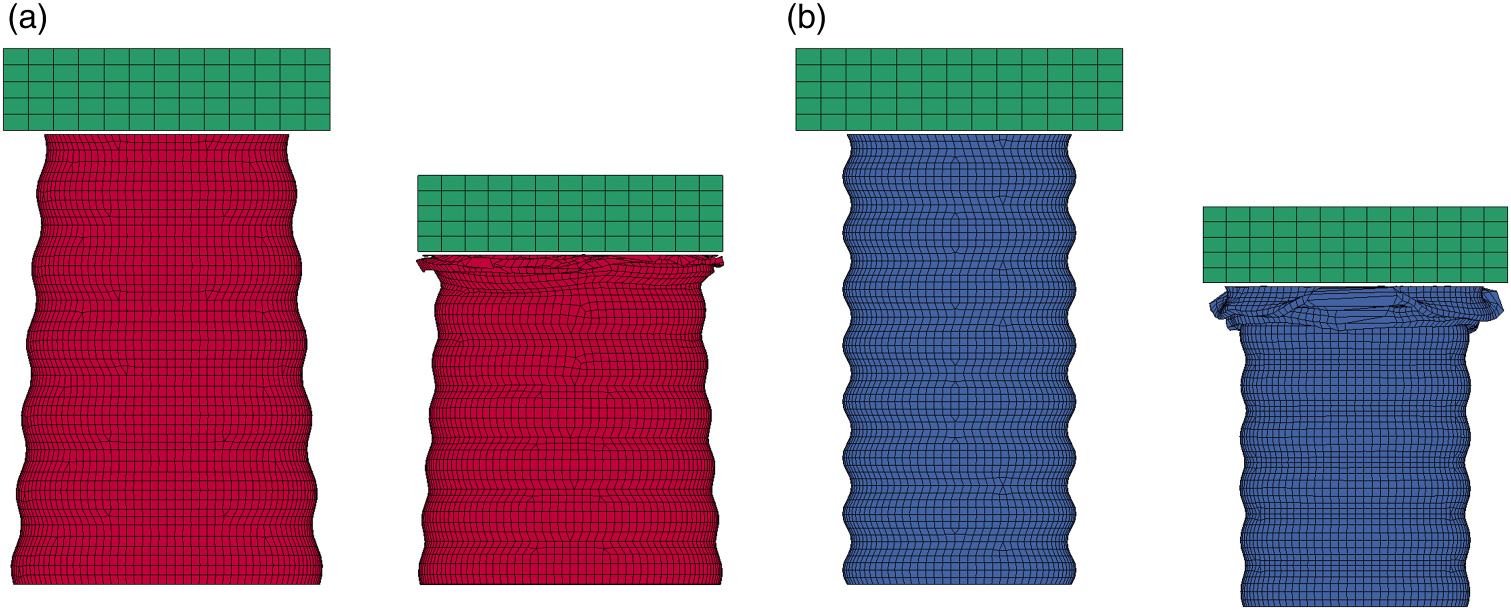


The numerical results and discussion
The results of the quasi-static crushing of the eight corrugated composite energy absorbers, as well as the straight conical and cylindrical control models, have been reported and compared with each other in this section. For the convenience of the author and readers, in this numerical parametric studies, the tubes are referred to with only the letters of C and F, denoting cylinder and frusta, respectively, followed by the number of corrugations in each tube. The force-displacement results of the conical and cylindrical composite energy absorbers could be seen in Figure 15. As it can be seen, the conical corrugated composite tubes exhibit higher peak forces. For a more in-detail analysis, Table 3 displays the crashworthiness parameters for all the models. Like it was understood from the force-displacement results, for a set number of corrugations, conical tubes exhibit higher SEA, peak force, and mean force than the cylindrical tubes. However, except for one, as the peak forces that the cylindrical structures undergo are considerably lower than those of conical tubes, the CFEs of cylindrical tubes are negligibly higher owing to the fact that they have a closer value to their mean forces. As an illustration, the highest CFE is shown by the model C16. Nevertheless, the highest SEA, peak force, and mean force belongs to the model F16. Another conclusion that can be drawn, with the exception of one (model F16), is that with a rise in the number of corrugations, the values of crashworthiness parameters see a rise. Having discussed all above, when Figure 15 and Table 3 are mode closely analyzed, one outstanding edge of corrugated energy absorbers is once again highlighted in the results of the present study. As it can be seen and expected, in both conical and cylindrical categories, the straight control models exhibit higher peak forces than all corrugated models, and then a sudden drop in the force that the structure could undergo, which results in a much lower mean force and CFE than those of the corrugated ones. Force-displacement results of corrugated composite tubes (a) conical (b) cylindrical. Crashworthiness parameters of corrugated and control composite tubes.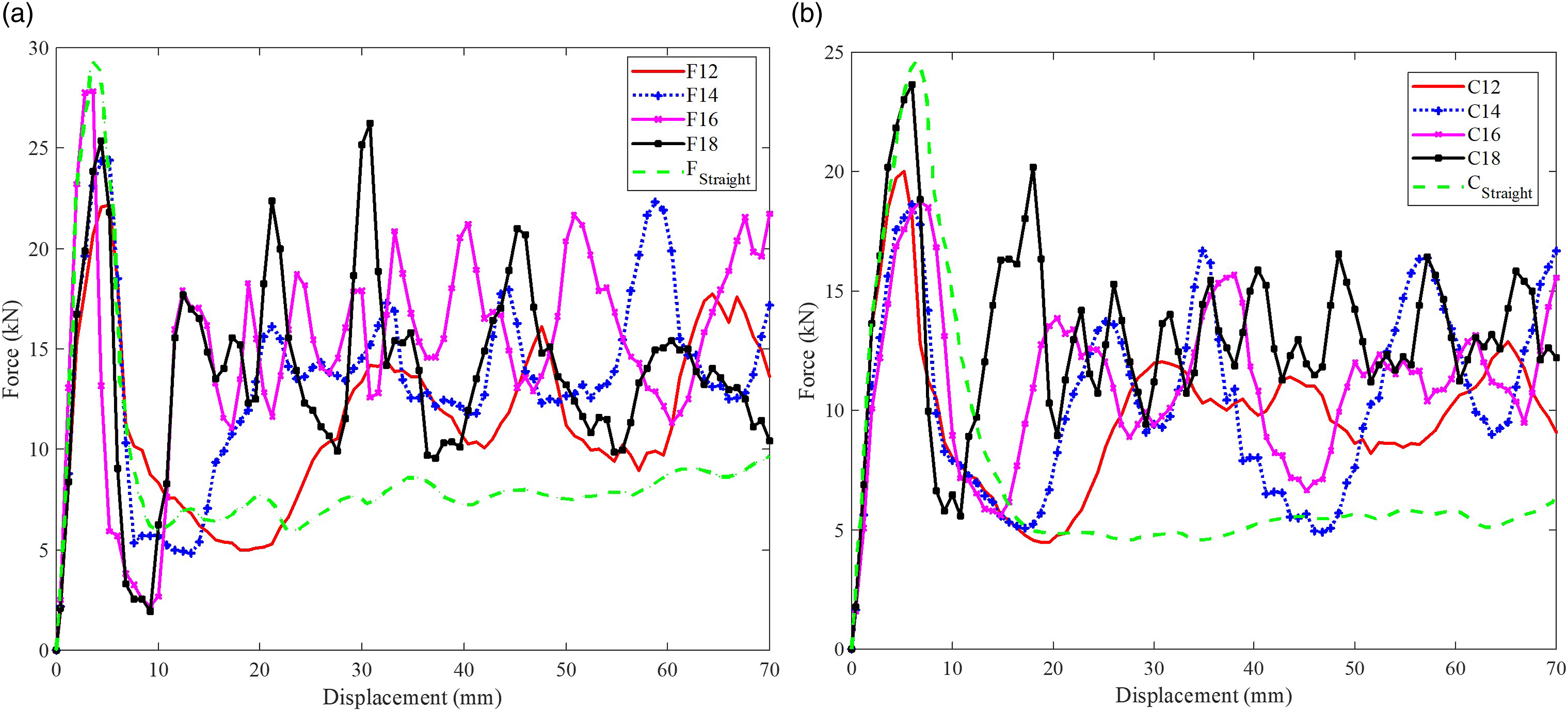
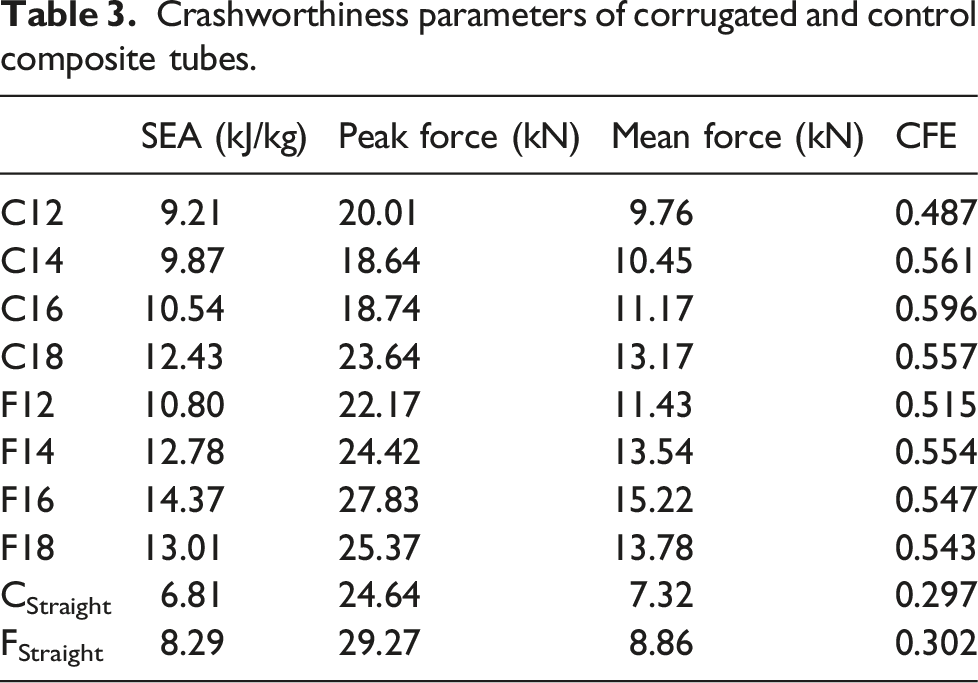
Figure 16 clearly shows the benefit of using circular corrugations in composite energy absorbers. Based on this figure, at initial stages of loading, the Von-Mises stress (VM stress) reaches its maximum in inward corrugated points. Through this mechanism, a more progressive crushing is expected than if a straight composite tube is used, for which fracture has been observed and reported in some cases at early stages of loading in the mid-section of the tube.
34
This also explains why the force for the straight tubes drop drastically (Figure 15), while for the case of corrugated tubes, crushing takes place more progressively and with every failure in the inward corrugated points (Figure 16), there is a rehardening in the results. This in turn, as discussed above, contributes to the considerably higher mean force and CFE for the corrugated models compared to the straight control models (Table 3). This can also explain the trend which was seen for the number of corrugations. The higher number of corrugations can cause the load to be distributed mostly in the corrugated parts, denoting a higher capacity for load bearing and a more progressive crushing. Additionally, if the top six corrugations are checked carefully, it can be seen that at the same timestep and load, stress is more uniformly distributed in the conical structure than in the cylindrical one. This shows that the conical structure has a higher capacity of load bearing, which was already observed in Table 3. Distribution of Von-Mises stress in corrugated conical and cylindrical composite energy absorbers at initial steps of loading (before the initiation of damage).
To further investigate the advantage of corrugated energy absorbers and how corrugations can impact the progressive crushing of the tube, Figure 17 has been included. As it can be seen, at a higher load, the maximum Von-Mises stress will be on the first outward corrugation. This will smoothen the progressive failure. In both experiment and simulation, it can be seen that the failure starts from this point and by increasing the load, the next corrugation will lead the progressive crushing of the energy absorber. The beneficial impact of corrugations on the progressive crushing of the tubes.
A comparison of further crushing of the energy absorbers in experiments and simulations can also be checked in Figure 18. As it can be seen, a similar deformation is seen for the finite element models to that of the specimens in the experiment. Moreover, the higher load bearing capacity of the conical tubes is confirmed more tangibly as the crushing progresses. Comparison of the deformation of the tubes in the experiment and simulation.
To have a better understanding of the crushing of the tubes and the damage that occurs in them, Figure 19 has been exhibited below. As it can be checked, like the specimens in the experiments, there are fragmentation and delamination taking place during the crushing of the conical and cylindrical corrugated composite tubes. Crushing and damage of the corrugated composite tubes.
As a limitation of the numerical study, we can point out that in the experiments, as described in Construction of Test Specimens, due to nature of filament winding process, the curvatures on the wax mandrels could not be tangibly covered by the fibers, and the outer layers have lower curvature radius compared with those of the inner layers that are completely corrugated (Figure 5). However, this matter has not been considered in the finite element models, where the tubes are uniformly thick and corrugated. Despite this simplifying assumption, the numerical results showed sensible agreement with the experimental data, denoting that the numerical framework developed and validated here can predict the energy absorption capacity of corrugated composite tubes with acceptable accuracy. This can also be based on the results of numerical study, where it was seen that there is stress concentration in the inward corrugated parts, and as the inner layers of the specimens are utterly corrugated, they have the dominant impact on the failure mechanism of the corrugated composite tubes.
Conclusion
In this paper, a novel method of manufacturing corrugated composite tubes was proposed. Subsequently, a comprehensive experimental and numerical study was conducted on these tubes. The following conclusions can be drawn: • The experiments proved that the conical corrugated composite tubes possess a higher capacity for energy absorption. • The peak force and mean force that the conical corrugated composite tubes could undergo are higher than those of cylindrical tubes. • The finite element models showed a sensible agreement with the experimental data. • Based on the numerical study, with a rise in the number of corrugations, better crashworthiness can be expected from both types of corrugated tubes. • Aligned with the experiments, the numerical results also confirmed higher energy absorption capability of conical corrugated composite tubes.
Footnotes
Declaration of conflicting interests
The author(s) declared no potential conflicts of interest with respect to the research, authorship, and/or publication of this article.
Funding
The author(s) received no financial support for the research, authorship, and/or publication of this article.
