
Abstract
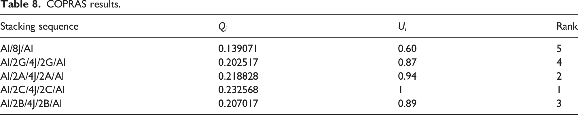
Fiber metal laminates (FMLs) are made by sandwiching a fiber-reinforced composite between thin layers of metal. FMLs are modern materials utilized in the manufacture of automobiles and aircraft because of their improved mechanical behavior compared to conventional metallic alloys. In the current study, different fabrics, that is, jute (J), glass (G), carbon (C), basalt (B), and aramid (A) were used as reinforcing components for composites that were sandwiched between two aluminum (Al) alloy sheets as a metal component in the proposed FMLs. The effect of hybridizing J-reinforced composite with different declared fabrics on the tensile response of the designed FMLs was experimentally investigated. The proposed FMLs were created using manual lay-up and compression casting techniques. Complex proportional assessment (COPRAS) was adapted to find the best FMLs structure that achieved the optimum tensile properties. The Al/2C/4J/2C/Al and Al/8J/Al structures were ranked first and last, respectively, based on COPRAS results.
Keywords
Highlights
• The designed fiber metal laminates (FMLs) were first prepared using manual lay-up and compression casting techniques. • Tensile tests were carried out on the designed FMLs according to the ASTM D3039 standard and the failed specimens were examined using optical and microscopic images. • Tensile properties were determined and discussed. Furthermore, complex proportional assessment (COPRAS) was applied to find the best FMLs structure. • All designed structures were ranked according to their best tensile properties. Al/2C/4J/2C/Al and Al/8J/Al structures were ranked first and last, respectively, based on COPRAS results.
Introduction
Fiber metal laminates (FMLs) are a class of hybrid materials constructed of alternatively stacked metal and fiber-reinforced composite layers or fiber-reinforced composite layers sandwiched between thin layers of metal.1–4 FMLs are composed of high-performance materials extensively used in the automobile and aircraft industries. 5 Natural fibers have been progressively used as reinforcing materials in polymer composites in recent years due to their low cost, availability, good thermal and acoustic protection, brilliant specific mechanical properties, renewability, and ability to be recycled.6–9 These benefits make natural fibers an attractive alternative to synthetic fibers for a variety of uses, either entirely or partially. The contemporary trend of replacing synthetic fibers in polymer composites with natural fibers can also be extended to FMLs. Many investigators in the literature have studied the mechanical properties of FMLs based on different types of natural fibers.10–15
Despite their appeal, natural fibers have a few drawbacks over synthetic fibers, including a high degree of inconsistency, poor moisture and impact resistance. By keeping the benefits of natural fibers while reducing some of their drawbacks, hybrid structures can be used.16–19 Because they can be readily customized to provide greater characteristics that are impossible to achieve with a single fiber reinforced composite, hybrid composites are becoming increasingly popular. 20 By combining the weaker fiber with a stronger one, hybridization can improve the mechanical, physical, and chemical properties of composites, consequently avoiding their disadvantages. As a result, the hybridization procedure may be used as a tactic to increase the use of various composites in various industrial applications.21–23
Although many researchers have looked at FMLs made of natural fibers, as stated above, there have been fewer studies done on FMLs made of natural/synthetic hybrid fibers. The tensile, compression, and flexural properties of natural/synthesis based FMLs were studied by Mohammed et al. 24 Flax (F), kenaf (K), carbon (C) fibers, aluminum (Al) alloy 2024 and epoxy were used as constituent materials. (C)/(F) fibers reinforced epoxy with (Al) sheets named (CAFRALL) and (C)/(K) fibers reinforced epoxy with (Al) sheets named (CAKRALL) were fabricated. The experimental results revealed that CAKRALL has the highest elasticity modulus of 4.4 GPa and exhibits better tensile and compressive strengths than CAFRALL, with an improvement of 14.8 and 20.4%, respectively. While CAKRALL has 33.7% lower flexural strength than CAFRALL. Feng et al. 25 found that the tensile strength of (K)/glass (G) FMLs is increased by the addition of G-fiber. When G-fabric is substituted for the center K-layers, the greatest fatigue resistance can be obtained.
Azghan and Farsani 26 and Azghan et al. 27 investigated how stacking patterns and heat cycling affected the flexural and tensile properties of FMLs. Al alloy sheets were employed for the skin, while the composites section consisted of four layers of basalt (B) fiber and/or G-fiber stacked in five different ways. The heat cycle time for FML samples was about 6 min for temperature cycles from 25 to 115°C. The samples' flexural and tensile characteristics were assessed after 55 heat cycles and compared with those of unexposed samples. The results of this investigation demonstrated that the flexural modulus is the highest for (B) fiber-based FML, the lowest for (G) fiber-based FML, and intermediate for B/G FMLs. FMLs with four layers of B-fiber display the highest levels of tensile strength, modulus, and energy absorption. The asymmetrically stacked sample with B and G-fibers, on the other hand, has the lowest strength and fracture energy. On the occasion of the samples exposed to thermal cycling, the highest and lowest thermal stabilities were detected, respectively, in B-fibers samples and asymmetrically stacked samples.
The effects of incorporating metal plates (Al2024-T3 and stainless steel 316L) into B/K fiber reinforced epoxy composites on Charpy impact behavior were investigated by Arpatappeh et al. 28 Results indicated that FMLs with Al-plates exhibit higher impact energy than those with steel plates. Zareei et al. 29 explored the tensile and interlaminar shear properties of environmentally-friendly FMLs with J-B fabrics as hybrid reinforcements, Al2024-T6 as a coating, and an epoxy as a matrix. Four hybrid structures, i.e., Al/2J/2B/2J/Al, Al/2B/2J/2B/Al, Al/J/B/J/B/J/B/Al, and Al/B/J/B/J/B/J/Al, were fabricated and tested. The outcomes displayed that J-fiber sandwiched by B-fiber gives the maximum tensile strength, interlaminar shear strength (ILSS), and modulus of elasticity. Microstructural analyses showed that the B-fiber has a powerful bond with the Al plies, whereas the J-fiber has a weak one. Additionally, it was discovered that the absence of diffusion leads to the existence of empty spaces between J-fibrils.
Abd El-baky et al. 30 investigated the influence of stacking sequences and relative fiber amounts on novel hybrid FMLs constructed on Al1050 and J-G fibers/epoxy composites. Results showed that hybridization may enhance the tensile and flexural characteristics of FMLs made from J-fabric. When G/epoxy laminas are substituted for partial J/epoxy laminas, the flexural strength of FMLs is increased. It is understood that adding high-strength fibers to a composite core results in a material with greater tensile properties but lower flexural resistance.
In addition to the mechanical properties of the designed material, selecting the best structure, i.e., making a decision about the best structure, is a critical issue to be concerned with. Multi-attribute decision-making (MADM) is a well-known branch of decision-making that deals with decision complications through a number of qualitative and quantitative criteria. A limited number of choices are ranked and chosen based on specified qualities. The multiple attribute-based decision issues should be solved using one of the many ways; in addition, the inconsistency between MADM method selection and the availability of the various MADM problem-solving strategies exists. These inconsistencies may result from different weighting methods, methods for choosing the "best" solution, objective scaling, and the addition of more parameters. Many scholarships use MADM methods, like the analytical hierarchy process (AHP), method of order preference similarity to the ideal solution (TOPSIS), preference ranking organization method for enrichment evaluations (PROMETHEE), and complex proportional assessment (COPRAS), to find the best option, which achieves the best response.31–36
COPRAS as one of the multi-attribute decision-making (MADM) methods, was employed in the current work to identify the stacking sequence that has the optimal tensile properties due to its ease compared with other multi-criteria decision-making methods. It is able to show a utility degree. On top of that, as reported by Podvezko 37 and Zavadskas et al. 38 COPRAS method provides extra accuracy in calculating alternative rankings as the assessment of the maximum and minimum criteria is done independently.39,40 The COPRAS method as the ranking method is a suitable strategy to prepare the information in a sensible and effective way. The strategy used by the COPRAS can process the criterion information from distinctive points based on a complex proportional calculation, which contains more accurate information compared with other strategies. 41 More details about COPRAS can be found in the literature.42,43
The COPRAS method has received enough attention from decision-makers. The target of these methods is to provide a convenient way for decision makers to select desirable alternatives. Among these methods, COPRAS has recently attracted much attention. As a compromising method, the COPRAS method determines a solution based on the ratio between the ideal solution and the worst-ideal solution. Unlike other MADM methods, the COPRAS method relies on a stepwise ranking and utilizes both significance and utility degrees to make a rational selection. The COPRAS-based technique demonstrates less estimation time, is extremely straight-forward and high plausibility of graphical elucidation as compared to other methods. The advantages of COPRAS method include: (a) Based on proportional assessments, it makes decisions based on benefit and cost; (b) it makes it easy to ascertain the gap between each alternative and the optimal one via the utility degrees. 44 Also, the primary benefit of this technique is its ease of use, effectiveness, and friendliness. 45 On the other hand, COPRAS may be less stable in comparison with the TOPSIS method in the case of data variation. Also, the results may be sensitive to a slight variation of data, and the dedicated ranks may be different from those obtained through other methods. 46
Due to its low cost, lightweight, and availability, jute (J) is considered a promising natural fiber.47–50 In spite of these advantages, J-fiber has some drawbacks and thus needs to be hybridized with other strong fibers. Based on the above-mentioned literature survey, quite little work has been undertaken with a view to investigating the properties of jute (J)-reinforced polymer FMLs and their hybrids. The current work aims to study the tensile properties of FMLs made of (J)/synthetic hybrid fibers. The designed FMLs were created using hand lay-up and compression casting methods. The proposed FMLs utilized epoxy with various fabrics in the composite component, including (J), glass (G), carbon (C), basalt (B), and aramid (A), sandwiched between two sheets of aluminum alloy (Al1050) with a thickness of 0.5 mm. The impact of hybridizing the declared fabrics with J-fabric/epoxy composites on the tensile response of the designed FMLs was evaluated. Also, the authors tried to obtain the FML structure, which achieves the best response, i.e., the optimum tensile properties. For this goal, a multi-attribute decision making (MADM) method called complex proportional assessment (COPRAS) was used. Since hybridization may be used as a tactic to increase the use of various composites in various industrial applications, the authors in this work performed a comparative study using different types of fabrics in order to overcome the drawbacks of J-fabric.
Material and methods
Materials
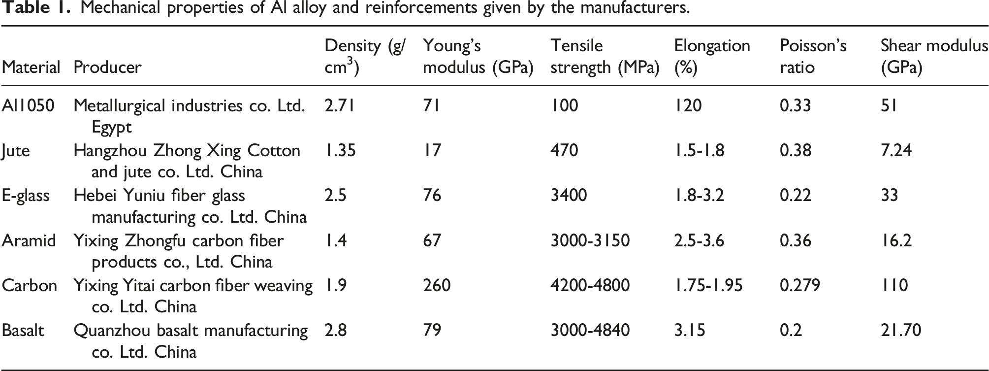
Mechanical properties of Al alloy and reinforcements given by the manufacturers.
Physical and mechanical properties of Kemapoxy 150 RGL given by the supplier.

Preparation of FMLs
FMLs were created using hand lay-up and compression casting, which have been used by many researchers,51,61,62 due to simplicity and minimum infrastructural requirements. Al-sheets underwent mechanical and chemical treatments to ensure good adhesion with polymer composites. Al-sheets go through a mechanical process that includes acetone rinsing, smooth abrading with # 400 grit sandpaper, tap water rinsing to remove the fine chips produced from the smooth abrading and the residual acetone excess, and oven drying.61,63
After that, HCl at 11% volumetric concentration was added to the mechanically treated Al-sheets to be acid washed to elevate its surface roughness. At room temperature, acid etching was carried out for 30 min. All linens were dried after being rinsed with tap water.
64
Al-sheets were subsequently soaked in a 5 wt % NaOH solution for 5 min at 70°C. The oxidized Al-sheets were dried in an oven to stabilize the oxide coating after being rinsed with tap water to remove any leftover oxide.51,59 The surface profile of Al-sheets before and after treatment is shown in Figure 1. As stated by Golru et al.,
65
surface treatment increases the surface roughness of Al-sheets. Increasing the surface roughness helps to introduce a good bond between Al-sheets and fabrics. The same results were obtained by Megahed et al.,
4
Abd El-baky et al.,23,60 and Alshahrani et al.
66
. Al-sheet (a) before and (b) after mechanical and chemical treatments.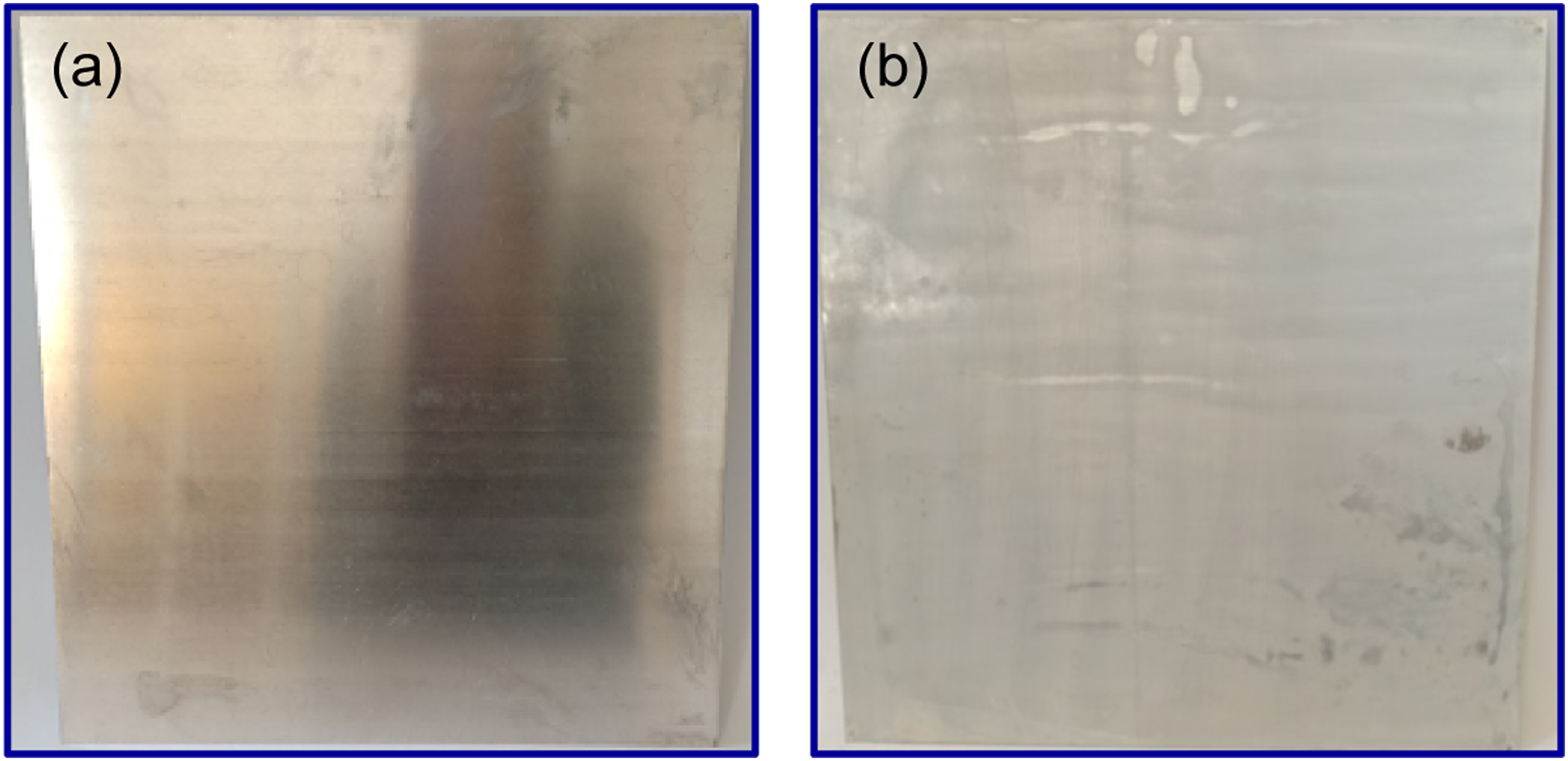
After that, the epoxy and its hardener were combined in a ratio of 2:1, respectively, based on the data sheet supplied by the producer. Then, a homogeneous layer of the mixture was applied over the treated Al-sheets and woven fabric layers. In this work, eight layers of fabrics were used for each designed structure, which determined the specimen thickness. The designed sequences are shown in Figure 2. For 24 h at room temperature, the constructed FMLs were held under 2.5 bars of pressure to cure and remove the voids and excess matrix. Pressurizing results in reduction of voids and removal of excess resin. Residual voids were minimal and insignificant. This agrees with the data provided by Moussavi-Torshizi et al.
67
. The mechanical tests were conducted after 21 days to ensure maximum strength and the full recovery of the specimens. No residual tension is created in FMLs because the cure procedure was carried out at room temperature.61,68 Stacking sequences for the designed FMLs.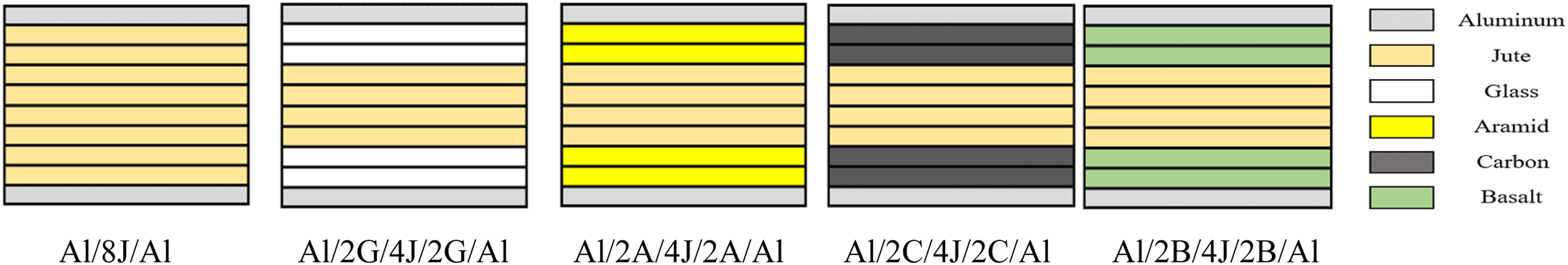
Tensile test
Tensile testing is a destructive, essential test in material science that provides fundamental design parameters such as the ultimate tensile strength (
The developed FMLs underwent a tensile test on a universal testing machine (Jinan WDW with 100 kN capacity) at a 2 mm/min strain rate. To guarantee constancy, three specimens for each FML were tested. The typical outcome was noted. According to ASTM D3039 the manufactured FMLs were sliced into strips with a size of 250 × 25 mm2 using a rotating band saw with a narrow pitch to prevent damage (delamination) throughout the cutting process. This cutting method has been used in many previous works.70–72 Each test specimen's gripping area was epoxy-glued to four rectangular Al-tabs. Refereeing to Khashaba,
70
Kumar et al.,
73
Selmy et al.,
74
and Ali et al.,
75
these tabs help in transferring the pressure from the machine to the specimen, lessening the stress concentration given by the grips, and protecting the specimen from crushing between the testing equipment's grips. Stress-strain curves (strain values calculated based on the recorded displacement of the test machine's actuator) were produced for each specimen in order to calculate the tensile properties, which include the ultimate tensile strength (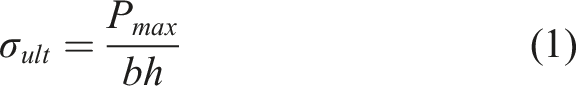
In addition to (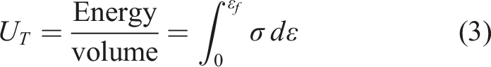
Two perpendicular strain gauges were involved on the contrasting surfaces of each test specimen to determine the actual tensile modulus (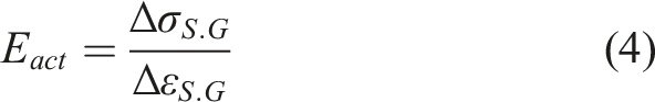
Decision-making
COPRAS method has been increasingly used for the quantitative and qualitatively evaluation. The aim of the evaluation is to choose the best alternatives, ranking the alternatives in the order of their significance. This method compares the alternatives and determines their priorities under the conflicting criteria by taking into account the criteria weights. 41 The stacking sequences investigated in this study were taken as design alternatives inside COPRAS framework, where they were rated according to their relative significance in relation to the performance criteria for tensile properties. Below is a description of how COPRAS and its equations were used, as stated in the literature review.39,40,42
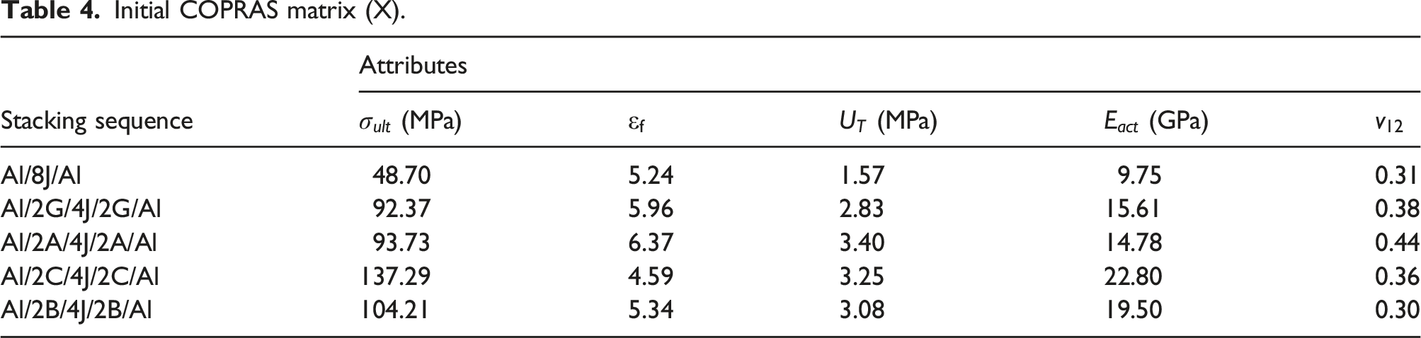
Create a preliminary decision matrix X. In order to use COPRAS, you must first create an initial choice matrix (X) that maps the contenders (the stacking sequences to their attributes) that is, their tensile qualities. The matrix X can be written as follows: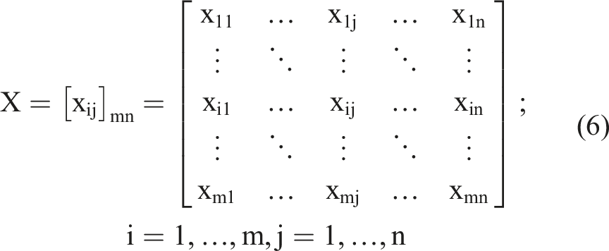
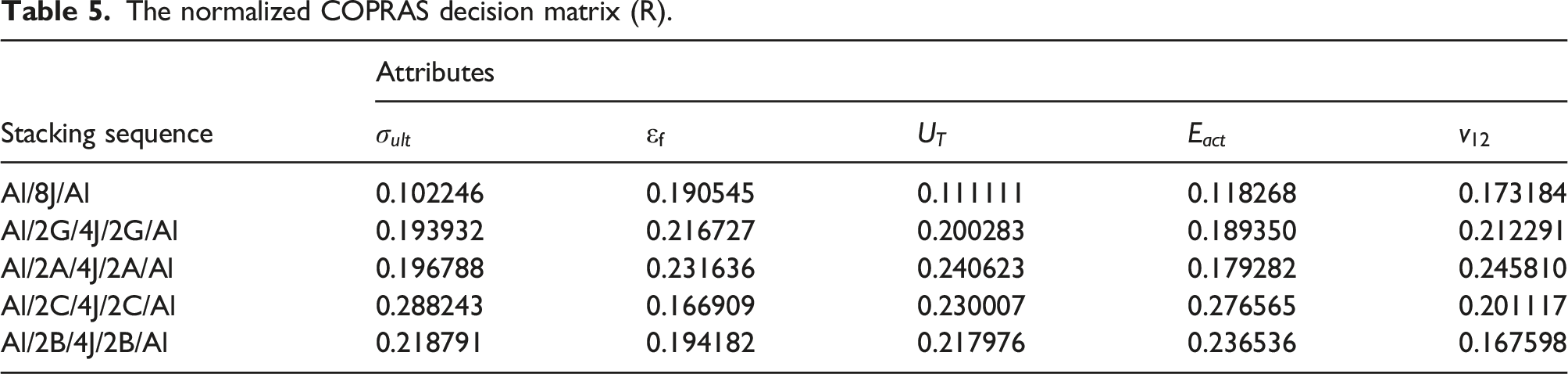
Make a decision matrix that is normalized “R”: The selection method is significantly more difficult because the modified design indicators have different units and cannot be directly related to one another. As a result, in order to make the design indications comparable, the matrix X must be changed into a no-dimensional one. Decision matrix R, which has no dimensions, is written as: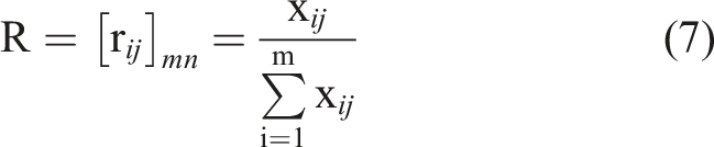
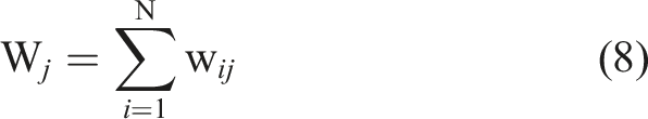
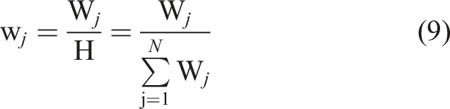
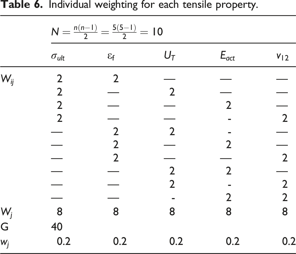
Calculate the individual weights of each attribute ( • The first step is to compare each pair of indicators separately. The total number of evaluations will be equal to N = (n (n - 1)/2). When the significance of the comparative tensile qualities differs for the selection process, the more significant indication should receive a score of 3, while the less significant indicator should receive a score of 1. On the other hand, if each of the compared indicators has equal weight in the selection process, both of them can receive a score of 2. • Second, after evaluation, the sum score for each tensile property can be calculated as follows: • Third, you may get the weightage of the
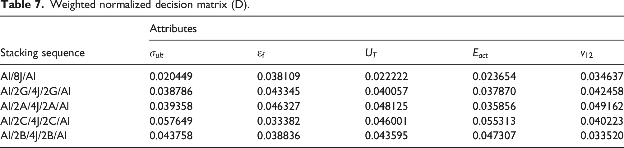
Determine the weighted normalized decision matrix D: The normalized matrix R can be multiplied by the specific weights assigned to each tensile attribute to obtain matrix D, which has the following notation:
Discover the summation of the positive and negative tensile properties for each stacking sequence alternative. The matrix D holds together positive and negative tensile properties denoted, respectively, as 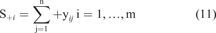
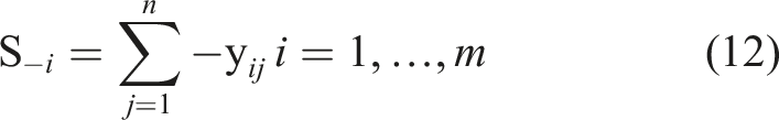
Compute the relative significance ( The design option with the highest 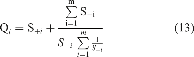
Results and discussions
Tensile test
Tensile properties
Figure 3 displays the stress-strain curves up to failure for tested FMLs. The strain values shown in Figure 3 were calculated based on the recorded displacement of the test machine's actuator. The stress-strain curves exhibit a nearly linear tendency before exhibiting a minor nonlinear trend up to the maximum force. A sudden failure was then noticed. As reported by Wang et al.83,84 the stress-strain curve is roughly divided into two portions. The first portion (I), which is characterized by a nearly linear behavior up to 0.3% strain, enables the measurement of the tensile modulus. The uneven curve in the second portion (Π) has a nonlinear behavior. That is due to the incidence and accumulation of potential damage in addition to fiber breakage. Compared to portion (I), the curve’s slope steadily declines. The curve abruptly drops after the load hits its maximum value, at which the ultimate tensile strength and the elongation at break can be calculated. Tensile stress-strain curves until the complete failure of specimens for the developed FMLs (strain values calculated based on the recorded displacement of the test machine's actuator).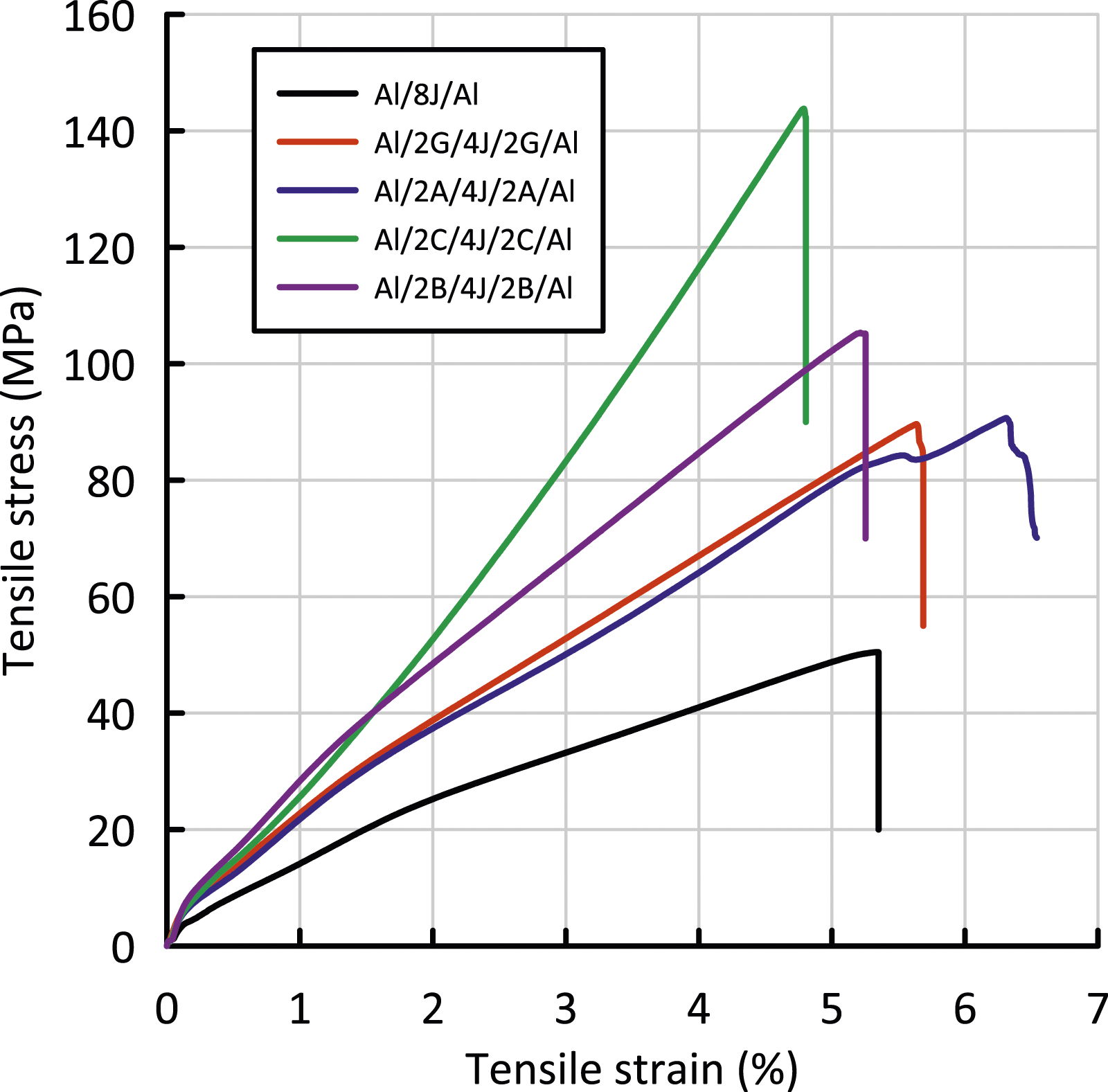
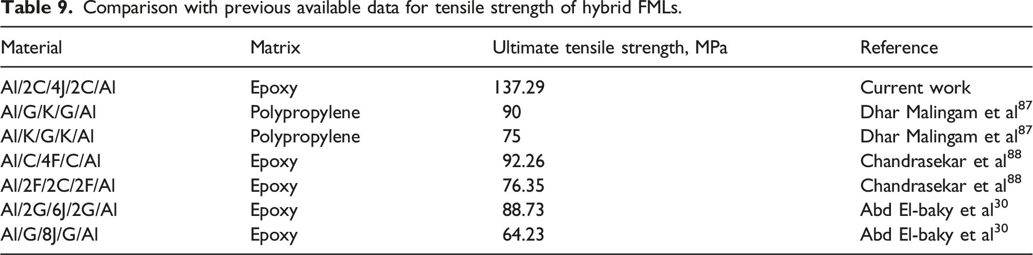
The obtained mechanical properties of the studied FMLs are shown in Figure 4. As shown in Figure 4(a), the Al/2C/4J/2C/Al specimen presents the highest ultimate tensile strength with a value of 137.29 MPa, an improvement of 181.9% over the Al/8J/Al specimen which records the lowest ultimate tensile strength of 48.7 MPa. Also, improvements of 89.67, 92.46, and 114% for, respectively, Al/2G/4J/2G/Al, Al/2A/4J/2A/Al, and Al/2B/4J/2B/Al were recorded. (a) Ultimate tensile strength, (b) failure strain, and (c) toughness modulus for the tested FMLs.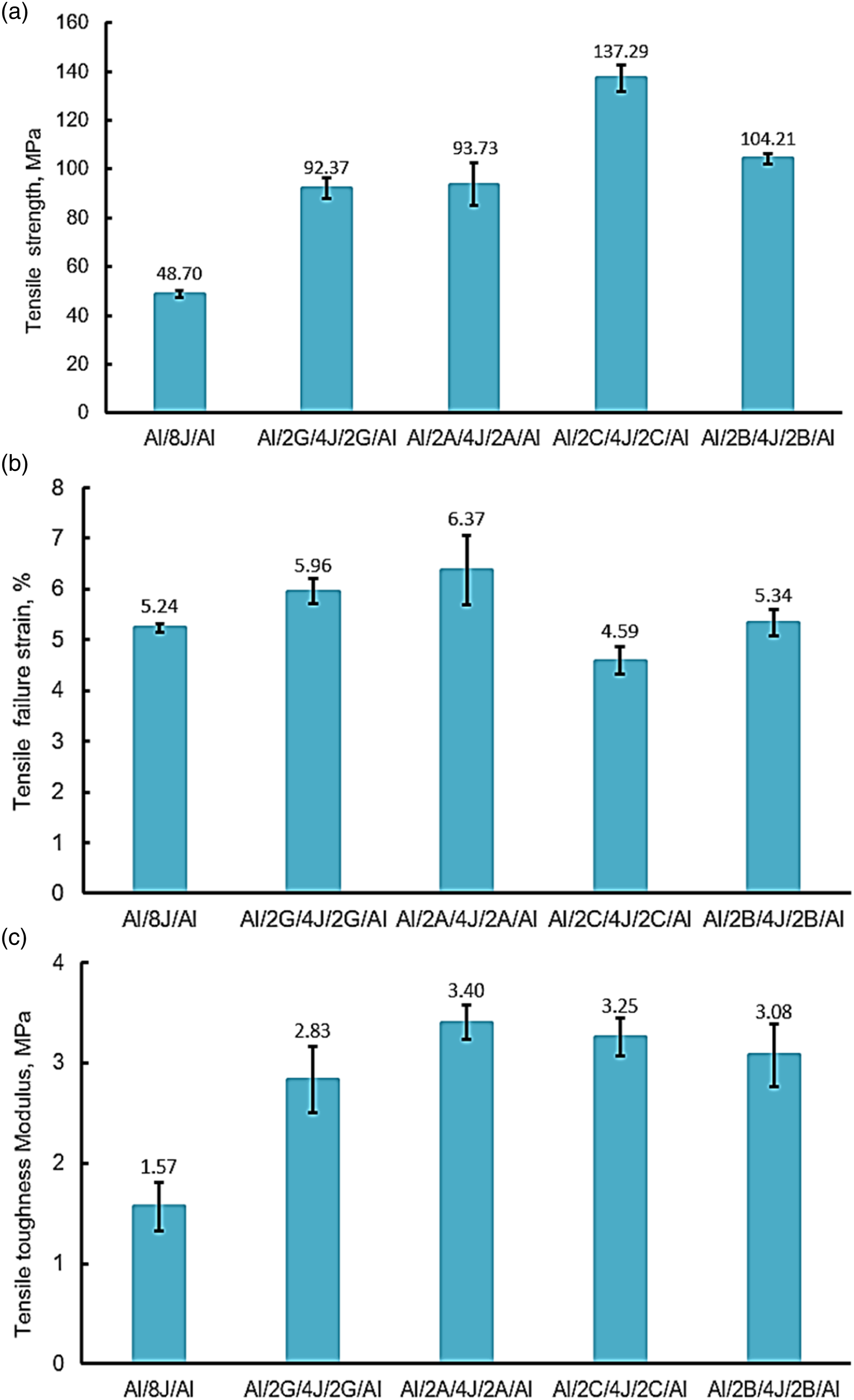
The tensile failure strain for the designed FMLs is presented in Figure 4(b). The highest and lowest failure strain values were observed for Al/2A/4J/2A and Al/2C/4J/2C/Al specimens, with values of 6.37 and 4.59%, respectively. It can be noted that the tensile failure strain of the Al/8J/Al specimen increased by 13.74, 21.56 and 1.90% for Al/2G/4J/2G/Al, Al/2A/4J/2A/Al, and Al/2B/4J/2B/Al, respectively. While it decreased by 12.40% compared with the Al/2C/4J/2C/Al specimen. It is clear that the hybridization of J-fiber with G, A, C, and B-fabrics significantly influences the tensile failure strain.
The tensile toughness modulus of the manufactured FMLs is shown in Figure 4 (c). With values of 3.40 and 1.57 MPa, respectively, the Al/2A/4J/2A/Al and Al/8J/Al specimens showed the greatest and lowest toughness modulus values. It is also important to observe that for Al/2G/4J/2G/Al, Al/2A/4J/2A/Al, Al/2C/4J/2C/Al, and Al/2B/4J/2B/Al specimens, the toughness modulus increased by 80.25, 116.56, 107, and 96.18%, respectively, compared with Al/8J/Al specimen.
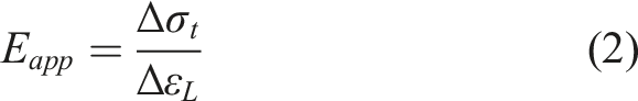
The stress-strain curves of the tested FMLs specimens, depending on the strain readings from the strain gauges, are shown in Figure 5. The actual Young’s modulus was determined at 0.3% longitudinal strain. It can be extracted from Figure 6 that hybridization of Al/8J/Al specimen improves the actual modulus of elasticity by 60.10, 51.59, 133.85, and 100% for Al/2G/4J/2G/Al, Al/2A/4J/2A/Al, Al/2C/4J/2C/Al, and Al/2B/4J/2B/Al specimens, respectively. For more illustration and comparison, the actual and apparent modulus of elasticity for proposed FMLs are presented in Figure 6. It is clear from Figure 6 that the apparent modulus of elasticity increased by 51.69, 44.10, 111.86, and 96.61% for Al/2G/4J/2G/Al, Al/2A/4J/2A/Al, Al/2C/4J/2C/Al, and Al/2B/4J/2B/Al specimens, respectively, compared with Al/8J/Al specimen. While the actual modulus of elasticity increased by 60.10, 51.59, 133.85, and 100%, respectively, for Al/2G/4J/2G/Al, Al/2A/4J/2A/Al, Al/2C/4J/2C/Al, and Al/2B/4J/2B/Al specimens. Tensile stress–strain curves for the tested FMLs (obtained from strain gauge readings in the first stage of loading i.e., initial linear part). Actual and apparent Young’s modulus for the tested FMLs.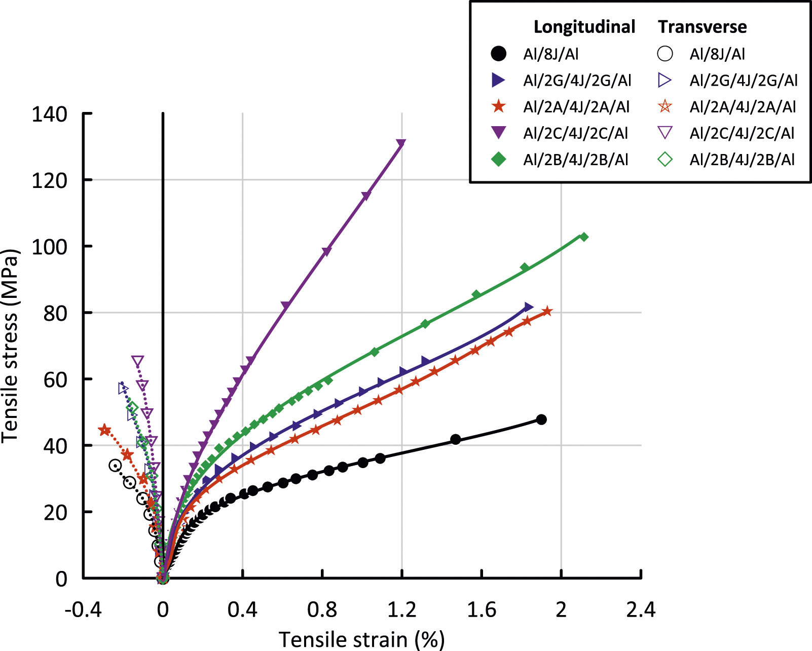
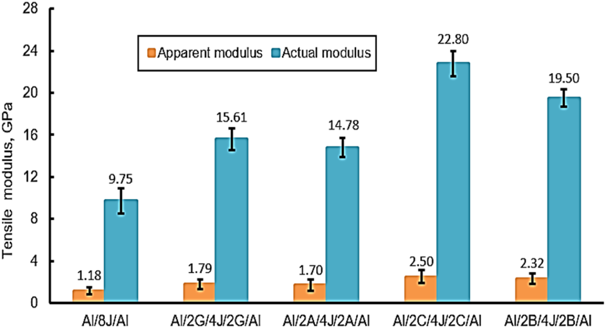
The Young's modulus, both apparent and actual, has the same tendency. The findings demonstrated that the actual modulus of elasticity values are considerably larger than their apparent values. This is brought on by a variety of factors, including slippage of the test specimen, shear deformation of the adhesive material separating the test specimen from the tabs, displacement brought on by gaps between joints and the testing machine's moving elements, and deformation of the frame columns, loading heads, and spindles. The apparent modulus of elasticity is lower than the actual modulus as a result of the additional lengthening caused by the generated displacements in the tested specimen. This finding was in agreement with those of Awd Allah et al. 80 and Selmy et al. 74
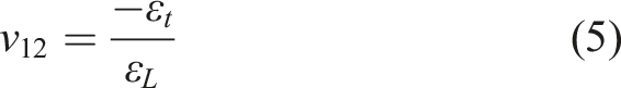
About Poisson’s ratio, it is clear from Figure 7 that the highest and lowest Poisson’s ratios were observed for Al/2A/4J/2A/Al and Al/2B/4J/2B/Al specimens with values of 0.44 and 0.30, respectively. Also, the hybridization improved Poisson’s ratio of Al/8J/Al specimen by 22.58, 41.94, and 16.13%, as shown respectively in Al/2G/4J/2G/Al, Al/2A/4J/2A/Al, and Al/2C/4J/2C/Al. The hybridization decreased Poisson’s ratio of the Al/8J/Al specimen by 3.23% as stated for the Al/2B/4J/2B/Al specimen. Poisson’s ratio for the tested FMLs.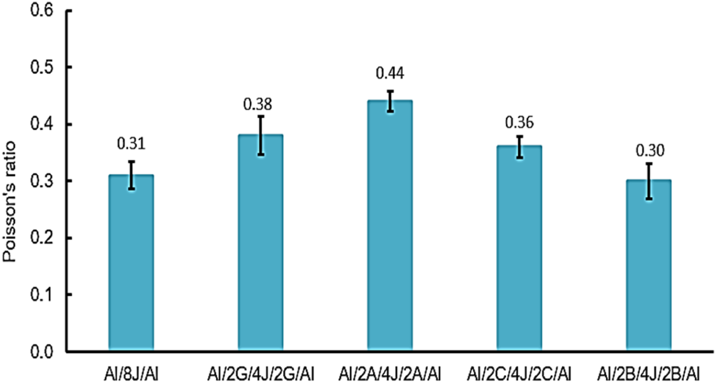
The ultimate tensile strength value from the second portion of the stress-strain curves, obtained from strain values calculated based on the recorded displacement of the test machine's actuator, can be used in the design requirements. The slope of the initial linear portion presents the apparent Young’s modulus. The apparent Young’s modulus cannot be used in the design. While the actual Young’s modulus obtained from the initial linear portion of the stress-strain curves, obtained from strain gauge readings, can be used in the design requirements.
Specimen failure modes under tensile load
The failure modes of tensile test specimens are presented in Figure 8. Severe debonding between the composite part and Al-layers as a result of poor bonding was seen for failed specimens, i.e., Al/8J/Al, Al/2G/4J/2G/Al, Al/2A/4J/2A/Al, Al/2C/4J/2C/Al, and Al/2B/4J/2B/Al. While a strong bond was observed among composite part layers for all tested specimens, excluding the Al/2A/4J/2A/Al specimen. Debonding between the composite constituents was also found in the Al/2A/4J/2A/Al specimen. For Al/8J/Al and Al/2A/4J/2A/Al specimens, the failure occurs near the grips. It is worth noting that the same failure mode, i.e., location, is considered one of the typical tensile test failure modes stated in ASTM D3039. Failure of specimens near the grip was due to the stress concentration, which was developed from the lateral compressive stress of the grips. This is consistent with that recorded by Khashaba and Seif.
85
Failure modes for the tested FMLs under tensile load.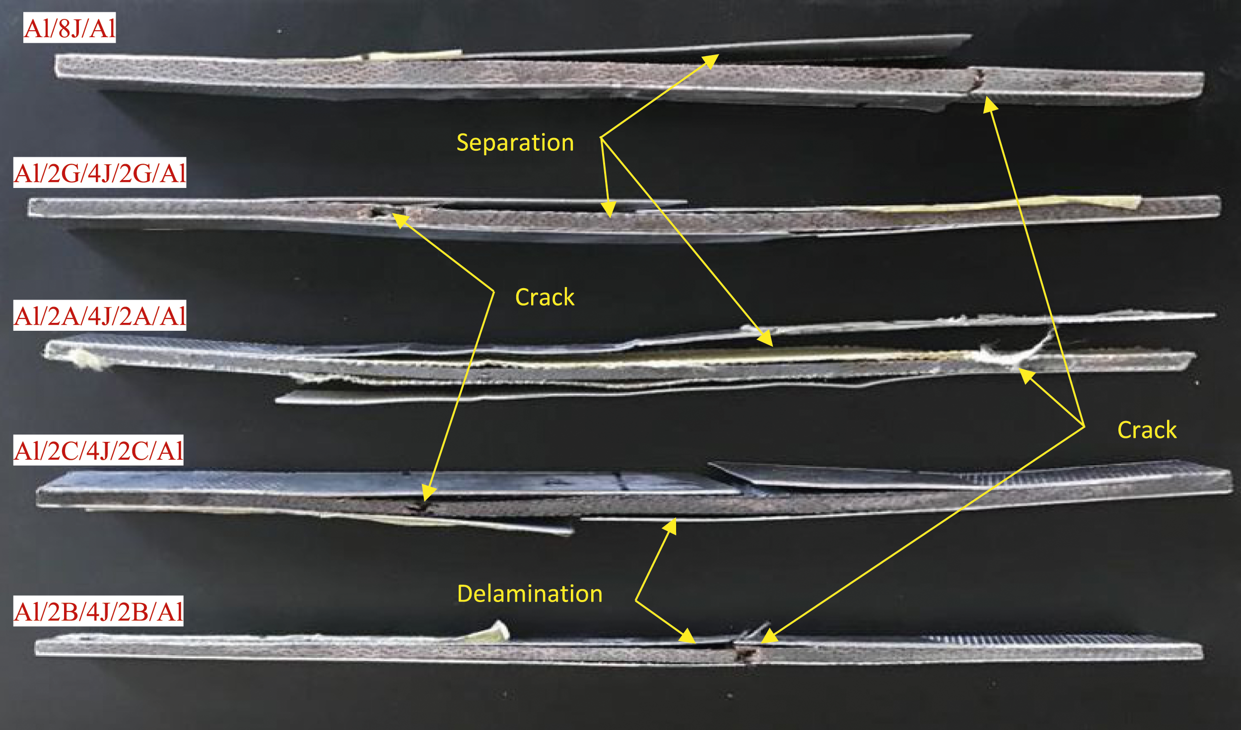
Microstructural inspection
Numerous variables, such as fiber type, orientation, volume proportion, matrix type, lay-up order, and fiber-matrix interfacial bonding, can affect the damage in polymer composites. The fracture surfaces of the failed specimens were analyzed using SEM JSM 6100 in order to better understand the failure of the hybrids under various stress situations. Gold was used to treat the location of the fracture, and it was subsequently preserved in an ionizer. A 20 kV voltage was supplied to the surfaces in order to obtain photos. Following the tension testing, microscope images were taken through the laminate's thickness. SEM images of the failed surfaces of tensile specimens are displayed in Figure 9. Fiber pullout, delamination, and cracking were clearly visible. SEM of failed tensile specimens.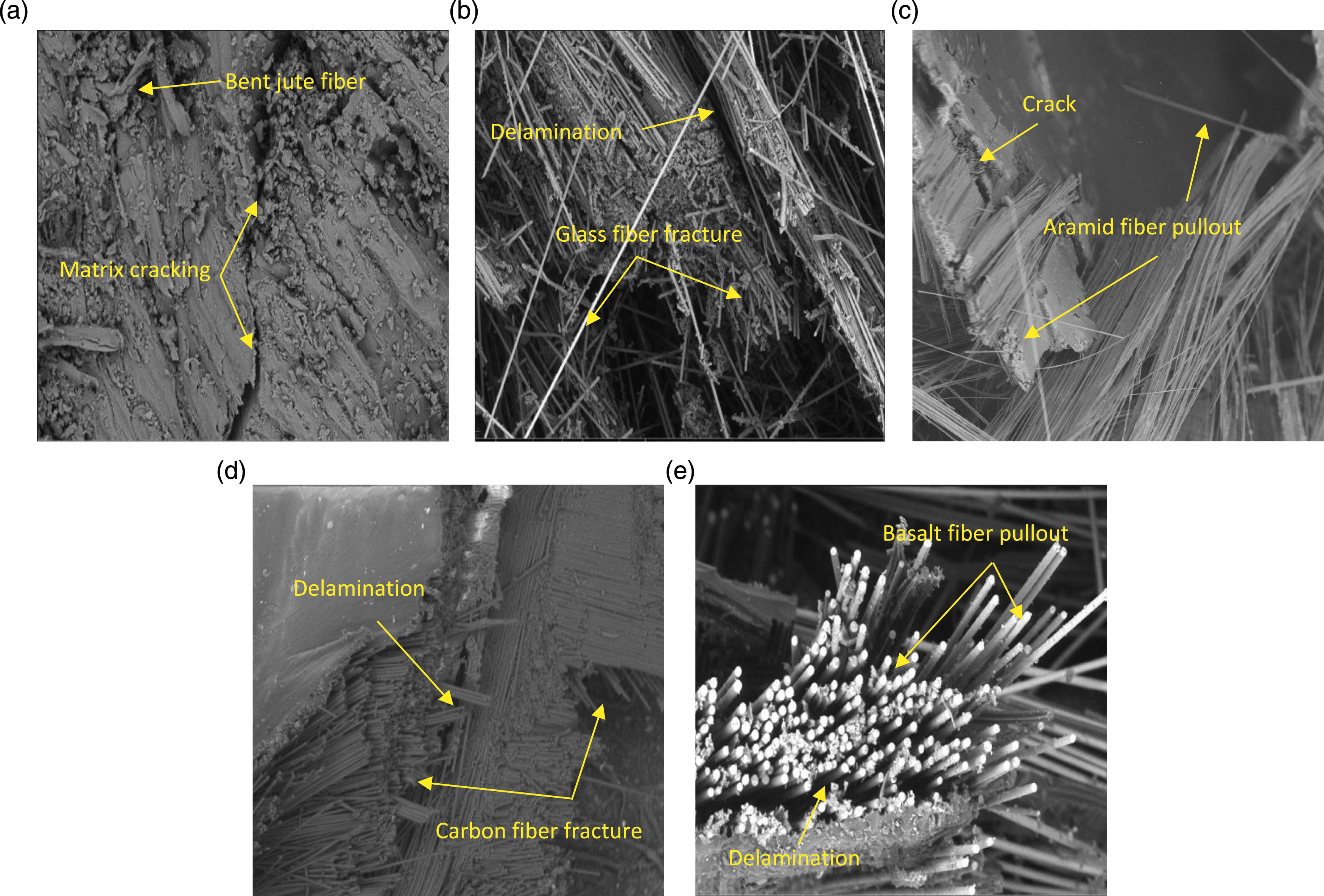
Scatter in the obtained results
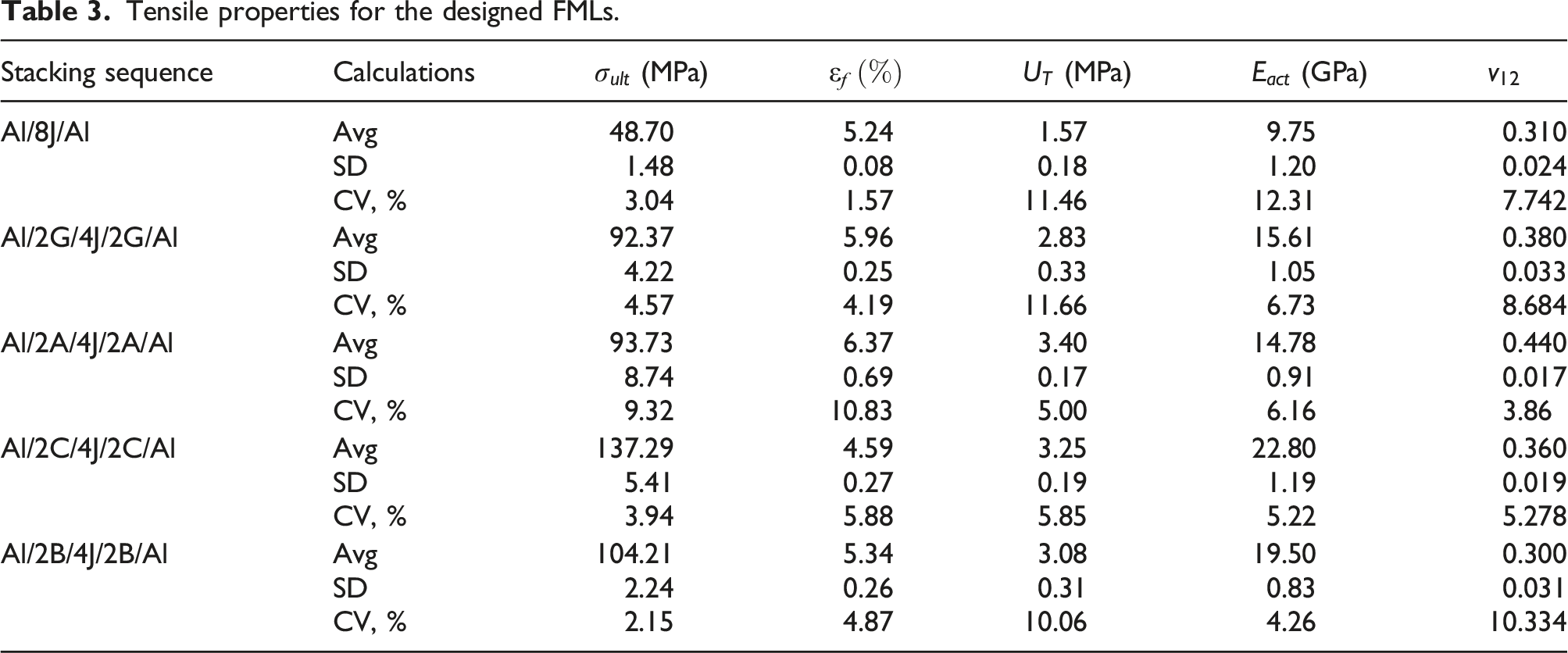
Tensile properties for the designed FMLs.
Determining the optimum FMLs structure
Initial COPRAS matrix (X).
The normalized COPRAS decision matrix (R).
Individual weighting for each tensile property.
Weighted normalized decision matrix (D).
COPRAS results.
Comparison between different materials
Comparison with previous available data for tensile strength of hybrid FMLs.
Future work
The current research can be expanded to look into additional critical FMLs related issues. The topics listed below are some suggestions for upcoming works: • Investigating the flexural, in-plane shear, interlaminar shear, and bearing behaviors of the designed FMLs. • Exploring the fatigue and creep behaviors of the designed FMLs. • Studying the effects of the hybridization procedure on low and high-velocity impacts. • Examining the effect of the tab alignment, tab material, tab angle, tab adhesive, grip type, grip pressure, and grip alignment on FMLs failure.
Conclusions
The goal of the present study is to experimentally examine the tensile properties of fiber metal laminates (FMLs). For this purpose, aluminum (Al) sheets, epoxy, and different types of fabrics, i.e., jute (J), glass (G), aramid (A), carbon (C), and basalt (B) were used to manufacture the designed FMLs. Specimens were prepared through hand layup and compression casting procedures. The effect of the hybridization between the J/epoxy composite and the other mentioned fabrics on the tensile properties was explored. Complex proportional assessment (COPRAS) was used to find the optimum FMLs structure. The following conclusions were drawn:
The hybridization was found to have significant effects on the tensile properties of the designed FMLs compared with the base structure in this work. i.e., the Al/8J/Al specimen. Adding G and A-fabrics to J-reinforced composite, i.e. Al/2G/4J/2G/Al and Al/2A/4J/2A/Al, respectively, enhances tensile properties, i.e. ultimate tensile strength, tensile strain to failure, tensile toughness modulus, and actual and apparent tensile modulus, and Poisson ratio of FMLs. All tensile properties of Al/8J/Al were improved by adding C and B-fabrics, i.e., Al/2C/4J/2C/Al and Al/2B/4J/2B/Al specimens, but the tensile failure strain and Poisson’s ratio were reduced, respectively. It was found that Al/2C/4J/2C/Al is the optimum hybrid FML structure in terms of tensile properties based on the COPRAS results. The fabricated hybrid FMLs are recommended for aerospace structures and automotive industry applications.
Footnotes
Acknowledgment
The author would like to thank Prince Sultan University for their support. The authors are thankful to the Deanship of Scientific Research at Najran University for funding this work, under the Research Groups Funding program grant code (NU/RG/SERC/12/8).
Declaration of conflicting interests
The author(s) declared no potential conflicts of interest with respect to the research, authorship, and/or publication of this article.
Funding
The author(s) disclosed receipt of the following financial support for the research, authorship, and/or publication of this article: This work was supported by the funding this work, under the Research Groups Funding program grant code (NU/RG/SERC/12/8).