
Abstract
Double-double (DD) configuration has been proposed as a new concept based on a double set of double helix [±ϕ/±ψ]n angles stacked up to form a composite laminate. This concept promises significant advantages over conventional layups for composite design optimization and manufacturing. This experimental study evaluated the performance of two elastically in-plane equivalent glass/epoxy laminates: a quadriaxial (Quad) [±45/(0/90)3]s and a double-double (DD) [±15/±75]4T. Mechanical tests were performed under cyclic uniaxial tensile-tensile load using unnotched and open hole specimens. Delamination initiating from the free edges resulted in premature failure of the unnotched DD specimens. For open hole specimens, fatigue tests results obtained from both stacking sequences showed similar performance. Ultimately, the study presented constitutes a valuable contribution to the understanding of fatigue behavior of double-double glass/epoxy laminates subjected to tensile cyclic loading.
Introduction
The field of composites design has been dominated by traditional quadriaxial (Quad) laminates for the past years. These laminates are based on combinations of 0°, ±45° and 90° plies, and have been the standard for composite structures. However, the restriction to four specific angle orientations has limited design and manufacturing of laminates,1,2 since the number of different permutations is limited while comparing to a continuous field of available combinations of angles.
Moreover, some well-known guidelines for laminate design3–5 are usually followed, such as mid-plane symmetry to avoid warpage, at least 10% of the plies in each of the 0°, ±45° and 90° directions (10% rule) and balanced layups to eliminate extension/shear coupling.6–8
This traditional layup design method has several drawbacks. The four angles specified and midplane symmetry, limits the number of possible layup combinations, to determine the optimum laminate for a given application. In addition, as the number of plies in a laminate increase, the number of potential layup combinations may increase to an unmanageable level. A different approach is of interest for improved layup optimization and to reduce the weight of composite structure .1,2,9
In this scenario, double-double (DD) configuration has been proposed as a new concept for designing and manufacturing composite laminates, in which two pairs of ply angles [±ϕ/±ψ] are stacked up to create a unique manufacturing opportunity to be simpler, faster produced, with lower weight and lower cost, as compared to traditional layups. 10 With the increase in number of repetitions of the 4-ply sub-laminate that forms the building block of a DD laminate, [B] matrix and its coupling effects diminish,2,8 homogeneity is approached, and mid-plane symmetry is no longer required to prevent warpage.11,12 While ply angle tailoring expands the possibilities of achieving optimum layup, 8 homogeneity and the consequent dispensation from the requirement of mid-plane symmetry facilitate topology optimization 13 and weight reduction can be achieved when tapering is also considered in the design. According to the literature, the weight reduction can reach up to 50%. 1
Simulation results show promise in optimization and weight saving of structures using DD laminates.12–17 Nonetheless, limited experimental results about the comparison of DD laminates and their traditional counterparts Quads have been published in the literature. A recent study shows an equivalent mechanical performance of carbon fiber reinforced plastic (CFRP) DD and Quad laminates under compression after impact (CAI) tests. 18
Most of the double-double research has focused on CFRP for aerospace applications. However, with the worldwide growth of wind energy industry and consequently increased interest in the properties glass fiber reinforced polymers (GFRP),19–21 understanding the properties of DD made of glass/epoxy laminates becomes important, mainly due to the potential advantages of DD over Quads regarding manufacturability, tapering capabilities, and design optimization.8,9 Wind turbine blades must be designed to withstand specified loads, which includes fatigue.22,23 In addition, the glass fiber reinforced plies used in the wind blade manufacturing are typically of larger thickness, as compared to the CFRP plies of the aerospace industry. The larger ply thickness is known to affect fatigue behavior. 24 Thus, the fatigue behavior of DD laminates made of glass fiber reinforced polymers (GFRP) must be well understood if these laminates are to be considered as candidates in the design of wind turbine blades.
This study compares the performance of GFRP laminates considering two layup configurations - Quad and DD - suited for wind turbine blades with the same in-plane elastic properties, under uniaxial cyclic tensile-tensile loading, using unnotched and open hole specimens. Strain versus number of cycles (ε-N) curves were plotted and stiffness degradation was evaluated throughout the experiments. In this sense, the study aims to understand the behavior of the novel family of DD laminates with material type and loading conditions typically considered in the design of wind turbine blades.
Experimental
Material and layup design
Engineering constants of E/Glass WindStrand 2000 and epoxy resin airstone 760E ply.
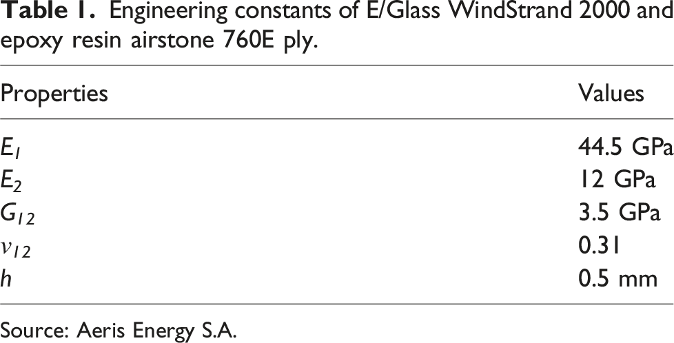
Source: Aeris Energy S.A.
Glass/epoxy laminates were designed using 16 plies to enable homogenization, which is a key concept of double-double layups that can be achieved with this number of plies, using repeats of a sub-laminate.11,25–27
The traditional Quad laminate was designed and manufactured using 0°, ±45° and 90° angles according to a layup utilized for the airfoil structure of a medium-power 40 kW wind turbine blade. 28 The region selected of the blade’s length for comparison was the one closest to the root of the wind blade, for this location is subjected to the highest fluctuant loads across the entire blade. The number of plies was scaled down while maintaining the original proportions of angles to achieve 16 plies. Hence, the Quad stacking sequence was [±45/(0/90)3]s.
The equivalent DD laminate was designed for the same in-plane stiffness and strength as the reference Quad using equations (1) and (2) to obtain the ϕ and ψ angles.8,12,27,29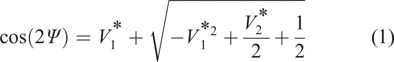

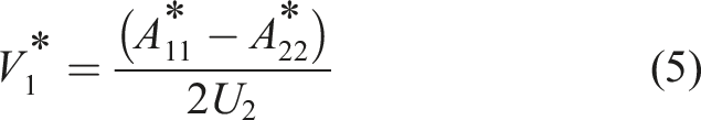
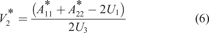
Lamination parameters V
1
* and V
2
* were calculated using equations (5) and (6), where A
11
* and A
22
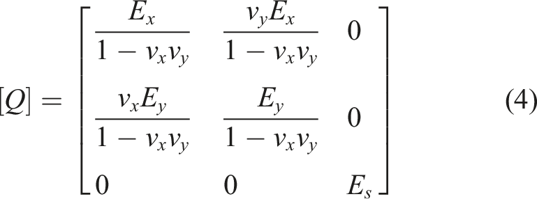
* are the components of the stiffness matrix [A] normalized by the laminate thickness h, as shown in equation (3), while U
1
, U
2
, and U
3
are linear combinations of elements of the reduced stiffness matrix [Q] 30,31 (equation (4) obtained using equations (7)-(9).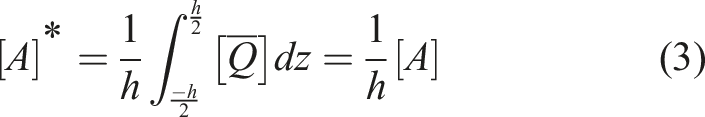


Using the equations presented, the equivalent DD laminate layup was defined as [±15/±75]4T.
The normalized stiffness matrix [A]* for the Quad [±45/(0/90)3]s and the equivalent DD laminate [±15/±75]4T are shown in equation (10).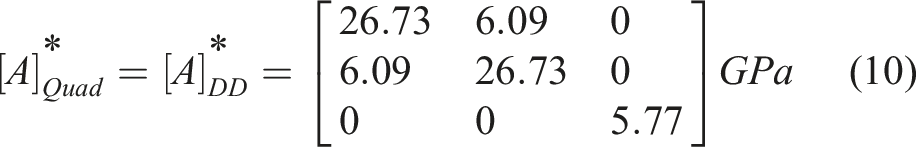
Normalized extension-bending coupling stiffness matrix [B]* can be obtained according to equation (11).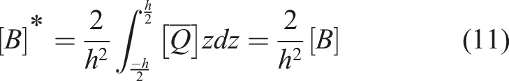
Bending-extensional coupling is eliminated by the symmetric stacking sequence of the Quad laminate and, thus, [B]* = 0. For the DD laminate [±15/±75]4T, [B]* is: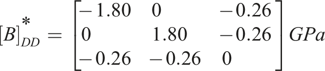
Nonzero elements of the [B]* matrix for the DD laminate indicate that there is extension-bending coupling. However, the effects of the small nonzero elements of
Normalized bending stiffness matrix [D]* can be obtained according to equation (12).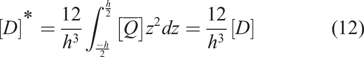
The calculated normalized stiffness matrices [D]* for the Quad and the equivalent DD laminate are shown in equation (13) for completeness.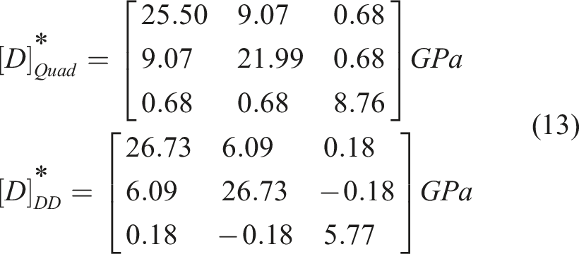
Thus, as homogenization is approached in DD laminates, the flexural and in-plane stiffnesses, [A]* and [D]*, converge.
Quasi-static tensile tests
Tensile tests were performed in five unnotched and five open hole specimens for each of the laminates using an AGI-300 kN Shimadzu tensile tester, following the recommendations of ASTM D 3039 32 for unnotched and ASTM D 5766 33 for open hole specimens. Nominal dimensions of unnotched specimens were 250 mm (length), 127 mm (gage length), 25 mm (width) and 8 mm (thickness). For open hole specimens, the dimensions were 250 mm (length), 127 mm (gage length) and 36 mm (width) with a hole of 6 mm diameter drilled at the center of the specimen, resulting in a width to diameter ratio (w/D) of 6, following recommendations of ASTM D 5766. Specimens were cut using a computer numerical controlled waterjet machine. Open hole specimens were drilled using a carbide drill. The holes were drilled undersized and reamed to final dimensions. End tabs were not used. The tests were carried out at room temperature (23 ± 2°C) with a displacement rate of 2 mm/min. Strains were measured by double linear strain gages located in the center of the unnotched specimens. The strain gages were connected to a digital precision multimeter Agilent 34970a Data Acquisition/Switch Unit.
The measured open hole tensile strength of specimens with hole can be normalized to the unnotched strength, as calculated using equation (14).34,35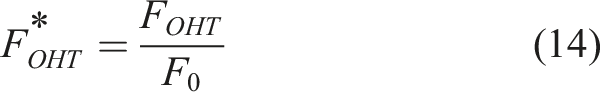
Fatigue tests
Fatigue tests were performed in an MTS LandMark Servohydraulic Universal Testing Machine following recommendations of ASTM 3479 36 and ASTM 7615, 37 for unnotched and open hole specimens, respectively.
The specimens were mounted in the hydraulic grips of the testing machine and a sinusoidal load was applied with ratio
Strain versus fatigue cycles (ε-N) diagrams were plotted. These diagrams were used to compare the performance of the laminates for unnotched and open hole conditions. Equations (15)39–41 was used for linear fitting of the results.
Hashin’s failure criterion was applied to evaluate the onset of damage. This failure criteria was later extended from static tensile loading to tensile-tensile fatigue loading and the failure modes classified as fiber failure calculated by equation (16) or matrix failure in equation (17).42–44 These criteria were utilized to assess the laminate’s performance under cyclic loading.

Results and discussion
Quasi-static tensile tests
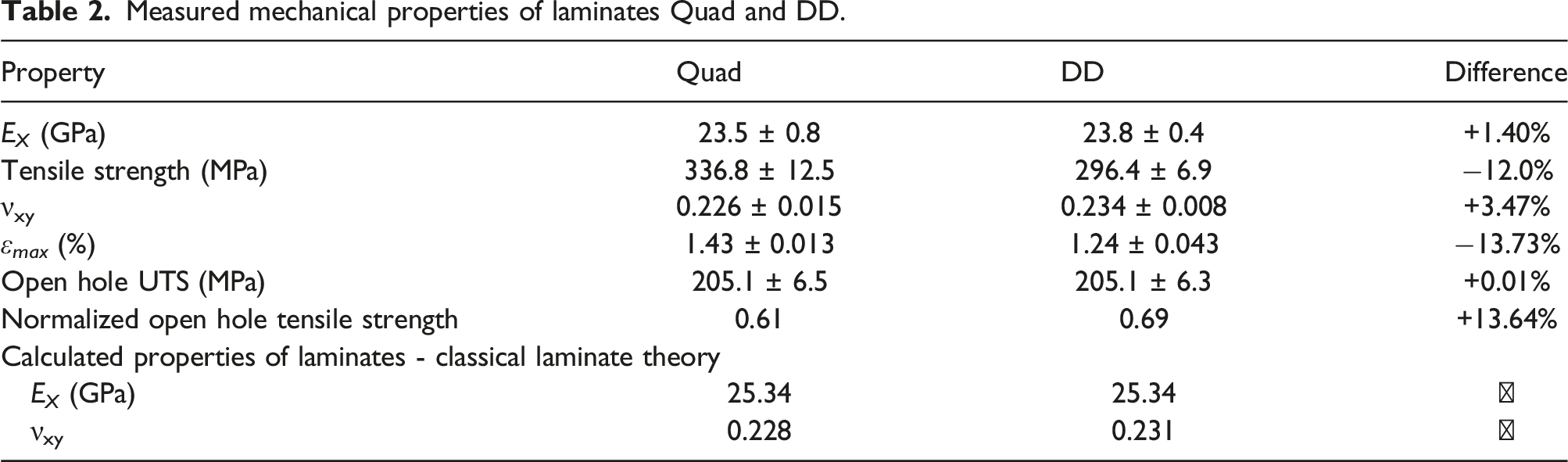
Measured mechanical properties of laminates Quad and DD.
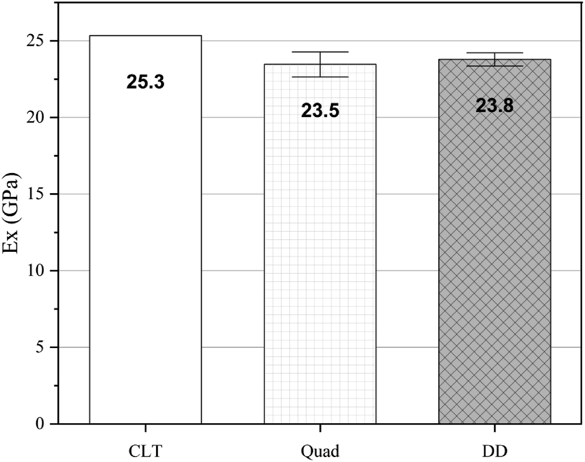
Longitudinal elastic modulus of Quad and DD laminates and CLT calculated modulus for both lay-ups.
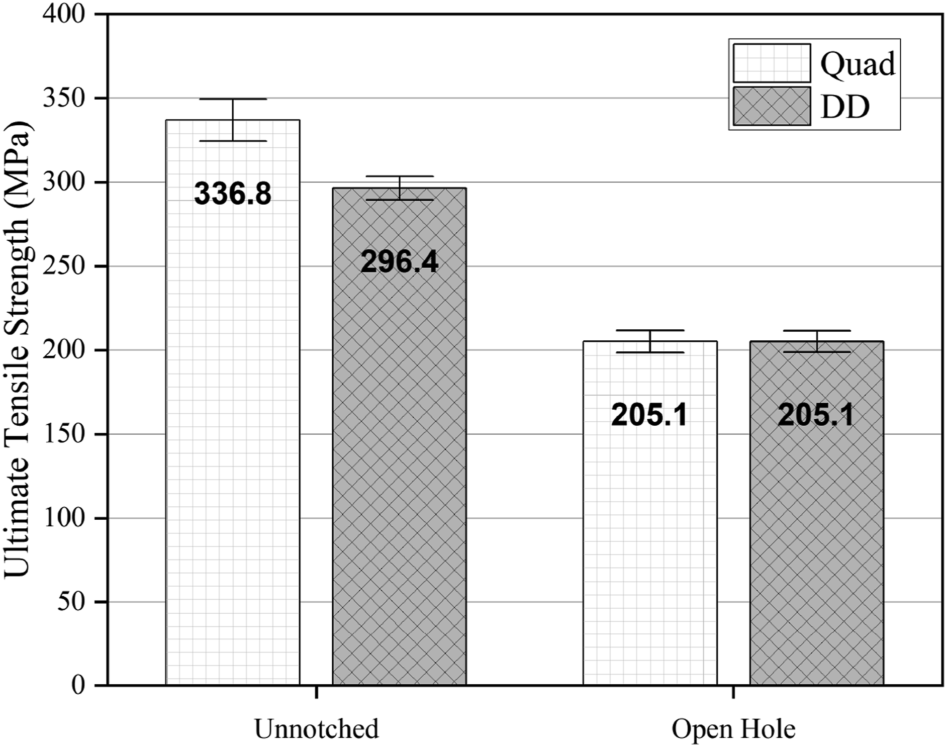
Tensile strength of laminates Quad and DD from unnotched and open hole specimens.
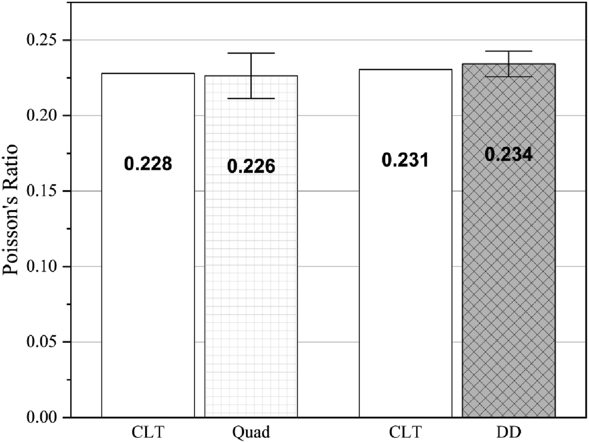
Poisson’s ratio of Quad and DD laminates and CLT calculated values for both lay-ups.
The types of damage observed in the test’s coupons are shown in Figure 4. The difference in damage shown in the pictures of unnotched specimens is related to interlaminar tridimensional stresses, which is responsible for causing premature catastrophic failure and significant load drops.47–51 This phenomenon is more prominent in the DD case, which might explain the earlier rupture of these coupons when compared to Quads since the effect is not observed on the latter. Failure modes after the quasi-static tensile test.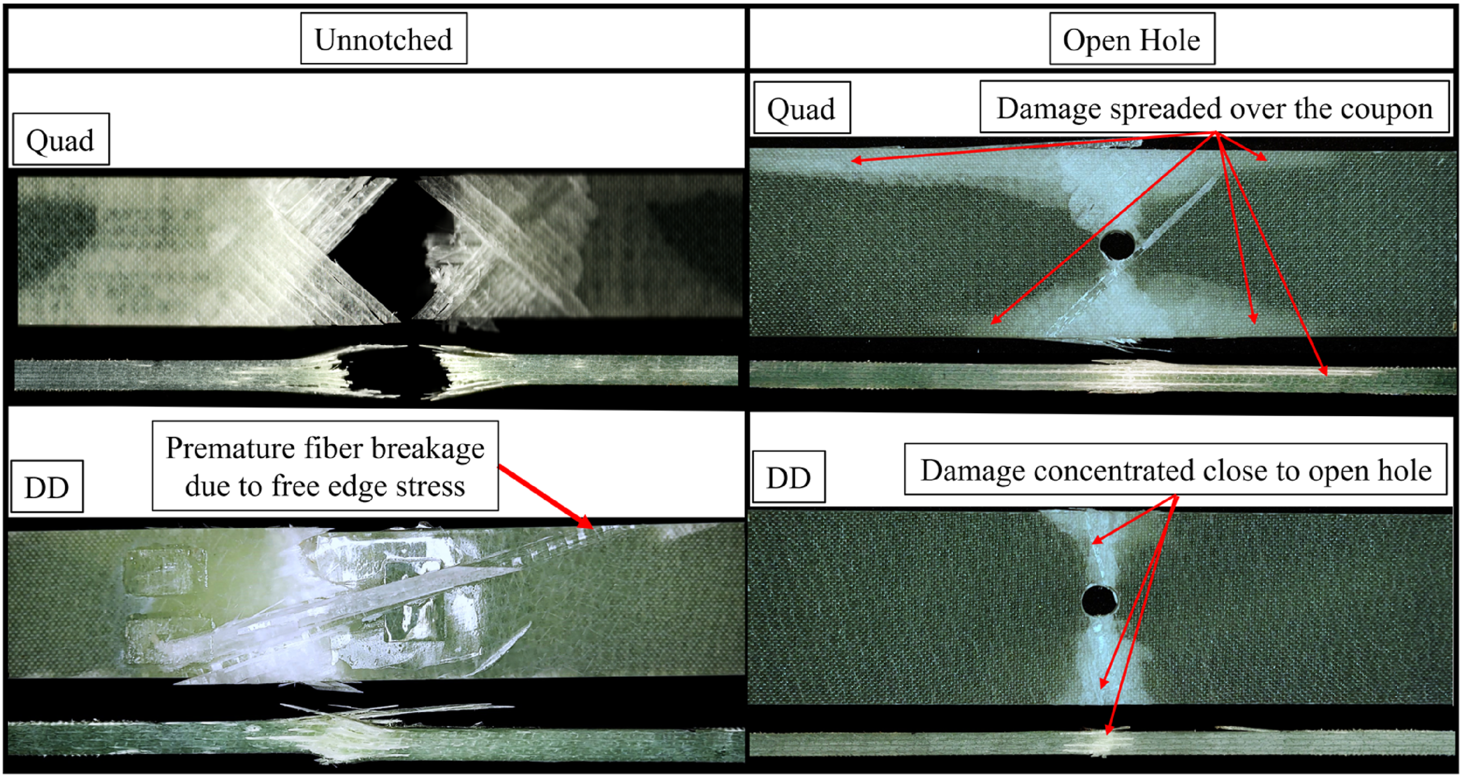
Regarding open hole tests, the results were similar for the two types of laminates and less disperse when compared with unnotched specimens, in accordance with previous studies.1,2,11 However, the damaged area after the tensile tests was significantly reduced in the DD open hole specimens (DD OH) when compared to the Quad open hole (Quad OH), as also shown in Figure 4. This might be related to the effect of homogenization throughout the specimen’s thickness.
The laminates – DD and Quad - are equivalent in terms of in-plane stiffness but showed different tensile strengths. As indicated in the damage analysis, this difference was due to higher stresses at the free edges of the DD laminate. These free edge interlaminar stresses may include normal (σz) and shear components (τyz, τxz). However, when specimens with open holes were compared, tensile strengths were similar for both laminates. Failure occurred in the notched region at a strength of about 65% of that of the baseline unnotched laminates. Thus, the stress concentration due to the hole proved more significant as stress riser than the complex stress state at the free edges.
Fatigue tests results
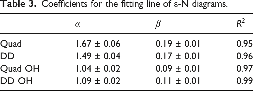
Coefficients for the fitting line of ε-N diagrams.
Unnotched specimens
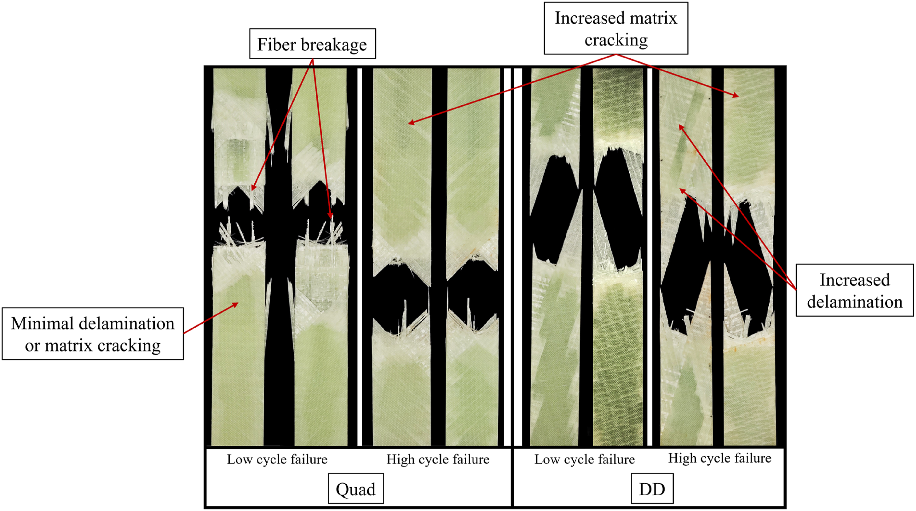
Figure 5 shows the comparison between ε-N curves for DD and Quad laminates. For lower cycles and higher strains, the dominant failure mode in fatigue of composites is fiber breakage,52,53 as Figure 6 shows, and determined by equation (16). Over the range of maximum strain per cycle evaluated, as shown in the fatigue life diagram (FLD) of Figure 5, the Quad laminates performed better since the Quads evaluated were composed of 37.5% of plies with fibers in the 0° direction while the DDs did not have any ply in this direction. Hence, a difference in terms of the number of cycles to achieve failure is observed in favor of the Quad. ε-N diagram for Quad and DD unnotched specimens. Different damage mechanisms in low vs high cycle failure.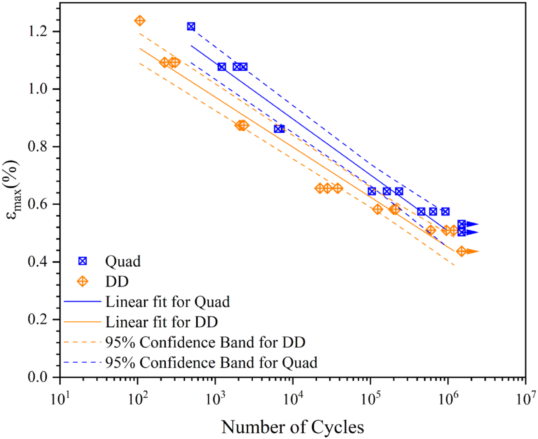
However, it is also known that coupon’s geometry can greatly influence testing results.50,54–58 Thus, considering the specimen’s width of 25 mm, free edge stresses had significant influence over the results in all conditions, especially at low load cycles. Nevertheless, when fatigue performance was normalized by the maximum static properties (εmax), DD and Quad displayed similar behavior, as shown in Figure 7. ε-N diagram normalized by εmax for Quad and DD unnotched specimens.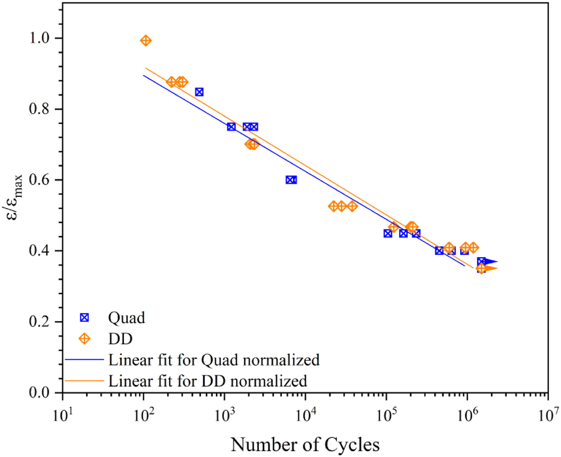
At higher number of cycles, when the progressive damage region of the fatigue life diagram is reached, matrix cracking and internal delaminations are the dominant damage modes,49,59 as Figure 6 also shows, and the results for both laminates were similar, as verified in Table 3 and Figure 5.
This phenomenon is also noticed by comparing the fitting parameters α and β for the two laminates. While both α and αmax are higher for quad laminates, β and βmin are lower for DD, resulting in an overlap of the confidence bands at the higher cycles areas, as shown in Figure 5.
Analysis of the damaged areas and damage progress in the specimens were used to help understanding these results corresponding to higher number of cycles. Figure 8 shows the top, side, and bottom views of a DD (a) and a Quad (b) specimen at run-out (1,500,000 cycles). For DD (Figure 8(a)), two different phenomena were observed taking place simultaneously: the free edge effect observed on the top portion of the coupon, causing an increasing level of delamination; and matrix crack seeing on the bottom surface. During cyclic loading it is well known the rapid growth rate of delaminations caused by free edge stresses, decreasing the stiffness of the laminate and causing premature failure of the coupon.60–64 Top, side and bottom views of a run-out (1,500,000 cycles) (a) DD coupon (b) Quad coupon.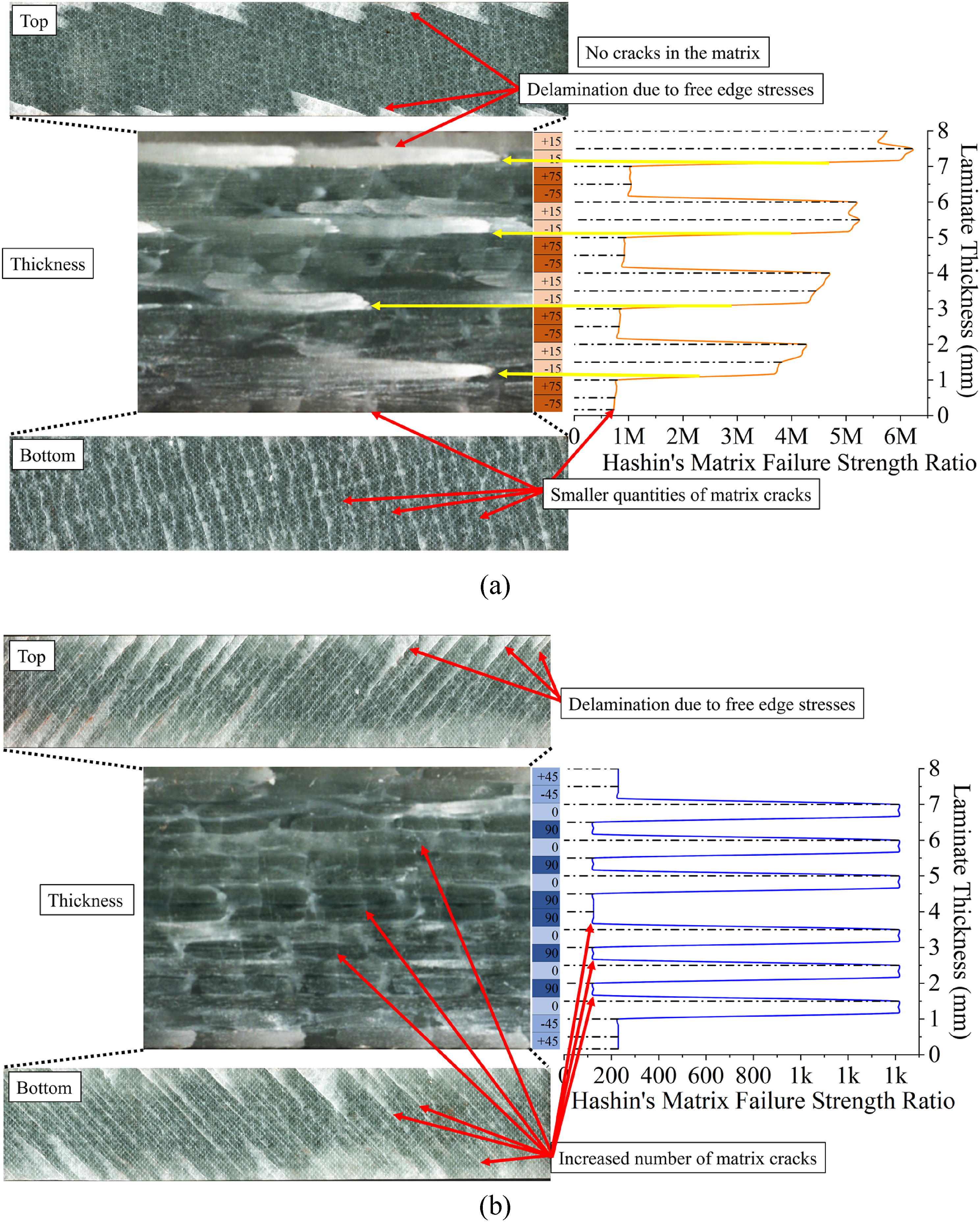
The strength ratio of Hashin’s matrix failure calculated using equation (17) is lower in the bottom portion of the laminate, as shown in Figure 8(a), where a pair of ±75° plies is located (the DD layup configuration is [±15/±75]4T). This indicates where failure initiates as the DD laminate is cycled and explains why the laminate has an increased amount of matrix cracks on this side of the coupon (bottom), while the top portion is more susceptible to free edge delamination.
The predominant failure mode in angle-py laminates with ply orientations less than 30° is delamination due to free edge stresses, which grows under cyclic loading, leading to stiffness degradation and premature failure, especially when the angles are over the ±10°-15° range, which is the case of the DD laminate studied in the present research.59,65,66
Figure 8(b) displays the typical profile damage of the [±45/(0/90)3]S Quad laminate at run-out (1,500,000 cycles). The increased number of matrix cracks was expected since this laminate is more susceptible to matrix cracking due to the presence of 90° plies, significantly reducing the strength ratio for the Hashin’s matrix failure criteria, as shown in the same figure. Although free edge stresses known to degrade stiffness throughout the fatigue tests are also present, this effect was found to be less intense when compared to DD’s.
Altogether, delaminations growing from the free edges of the narrow unnotched coupon heavily influenced fatigue results of DD laminates, as shown in Figure 9. These delaminations were also observed on quasi-static tests, however, in a much smaller extent when compared to the fatigue tests, since this phenomenon is predominant in cyclic loadings.
52
Damage propagation on the front and back sides, respectively, of a DD coupon during high cycle cyclic loading. σmax = 138.57 MPa and 212k cycles to failure.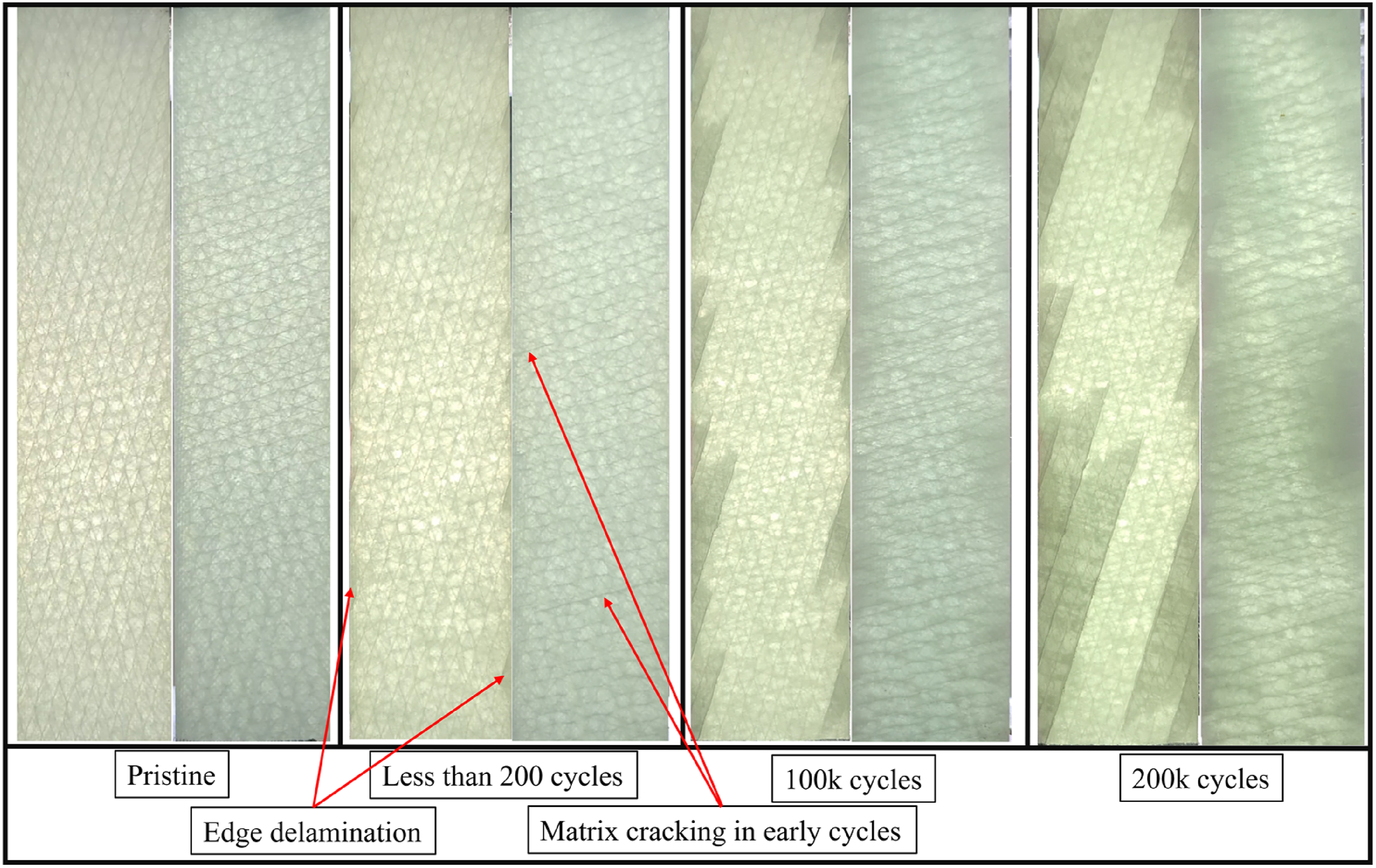
Open hole specimens
Because of the biased results obtained from unnotched tests, influenced by growth of delamination from the edges, specimens with open hole were used as stress riser to force failure in the notched region. By forcing failure away from the edges, open hole coupons can lead to a more reliable and consistent failure mode. 67
Maximum strain versus number of cycles (ε-N) for open hole specimens are presented in Figure 10, for DD and Quad. In this case, no significant difference between the two laminates – DD and Quad – or their respective confidence bands was observed, with both laminates showing similar performance throughout the entire range. ε-N diagram for Quad and DD open hole specimens.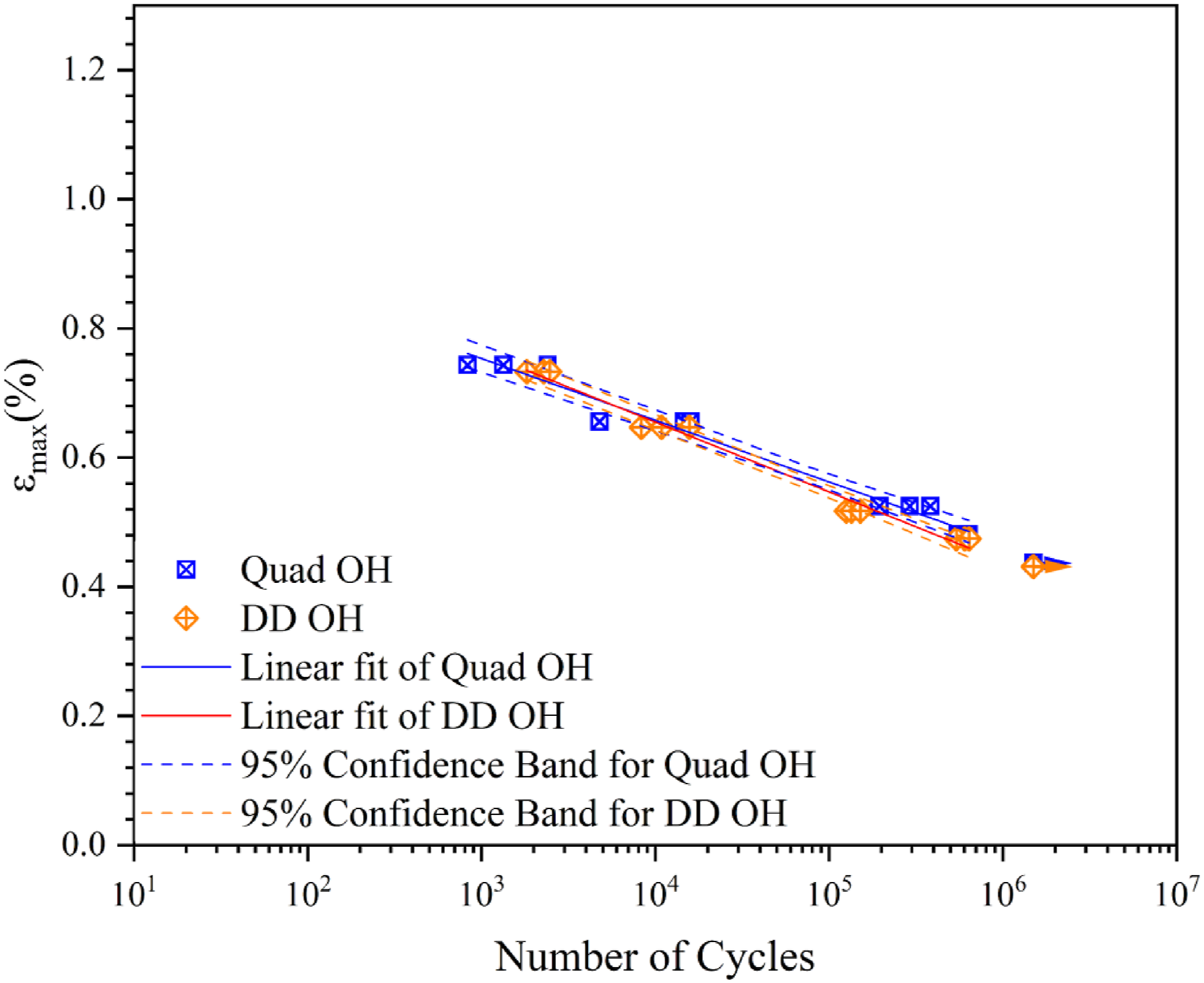
Despite the free edge stresses being reduced in this test condition, they are still present and may interfere with the results, though to a smaller extent as shown in Figure 11. It is also noticeable the smaller delaminated area around the open hole in the DD laminate when compared to the Quad. Damage comparison between a DD open hole specimen (free edge delaminations still present) and Quad open hole. Both cases failed short after 600k cycles with same load values.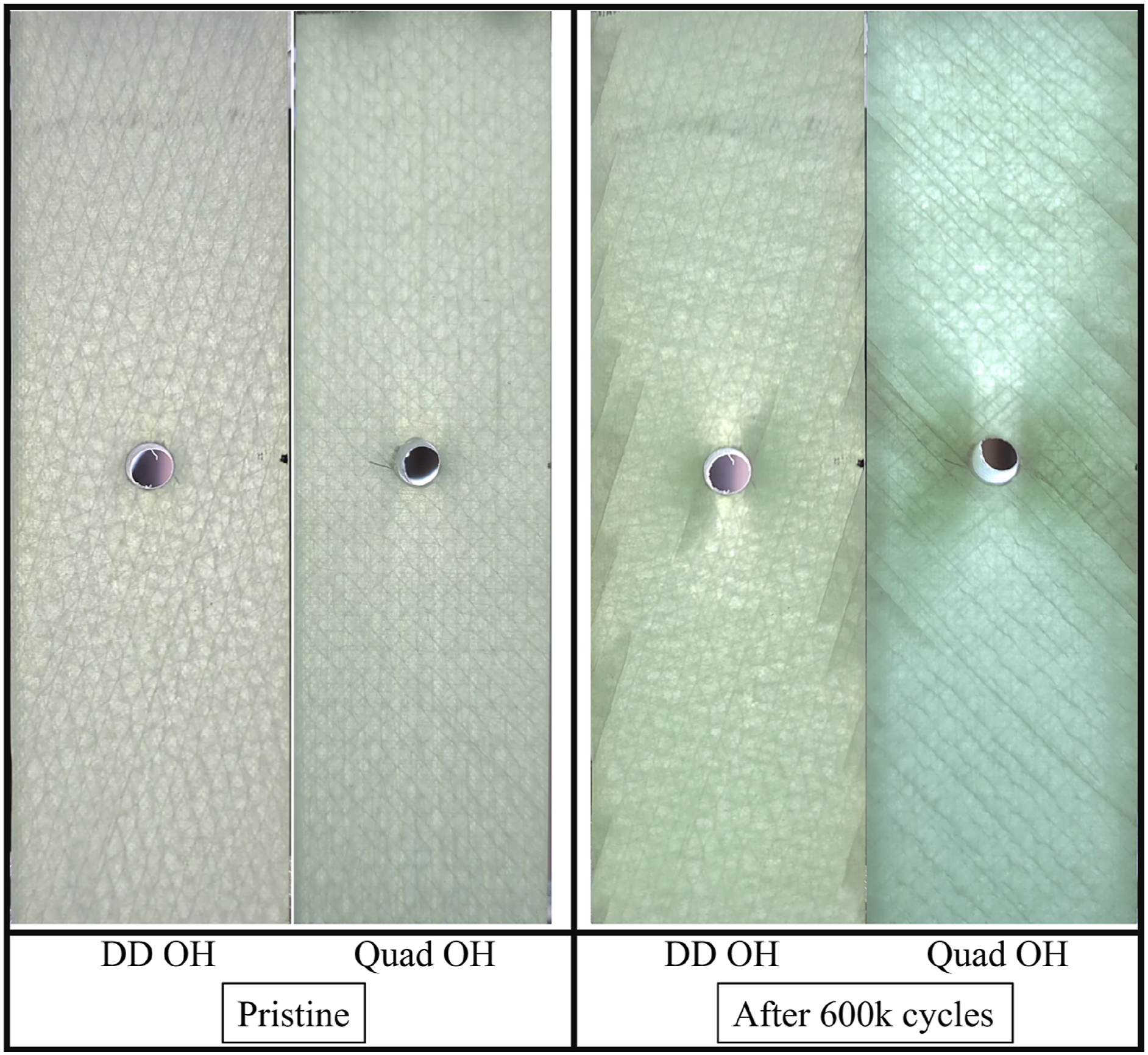
Comparison of the DD specimen in both unnotched and open hole conditions, indicates a difference in the delamination profile after the fatigue tests. In Figure 12, the areas of delaminations are significantly reduced in the presence of the open hole, restricting themselves to the hole proximity, while the delaminations on the unnotched specimen are spread out throughout the testing coupon. Damage throughout the thickness of DD specimens for unnotched and open hole conditions.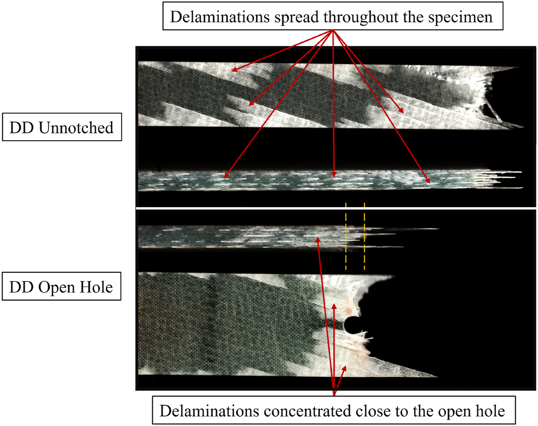
Summary of failure modes under cyclic loading
Figure 13 shows typical failure modes of Quad and DD for unnotched and open hole specimens under cyclic loading. No significant difference in failure modes was observed in the quad laminate from unnotched and open hole specimens. Splits and delaminations are observed at the gage area for unnotched specimens and at the hole for open hole specimens. Delaminations are also visible at the intersection of the surface ply and the free edge and grow gradually across the width of the specimen.
68
However, for DD laminates, a noteworthy reduction in edge delaminations was observed in open hole specimens. Fracture initiated at the edge of the hole and was dominated by the local stress concentration, showing some pull-out. Failure modes of Quad and DD from unnotched and open hole specimens under cyclic loading.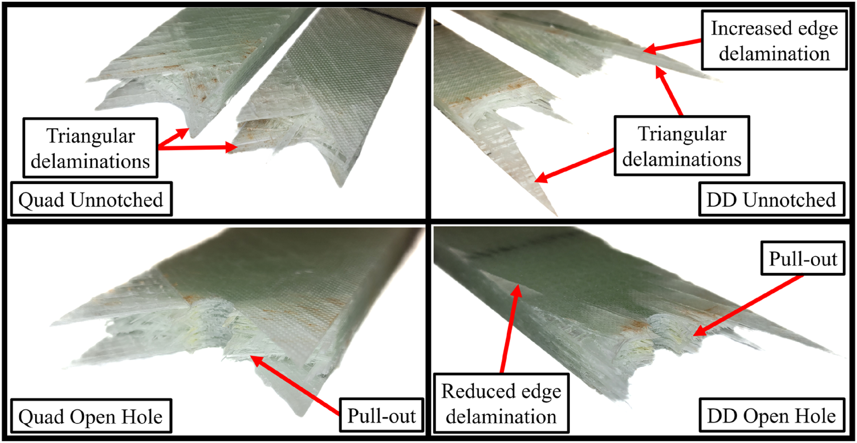
Stiffness degradation
With the aim of analyzing stiffness loss with increasing number of cycles, the relationship between stress and strain was evaluated during the experiment through the equipment built-in data acquisition system. Equation (18) shows the relation force (F)/displacement (u) with values assessed during the fatigue tests.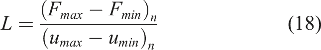
The relationship presented in equation (15) can be related to the coupon stiffness and its variation can be used to represent the stiffness degradation along the cyclic loading.69,70
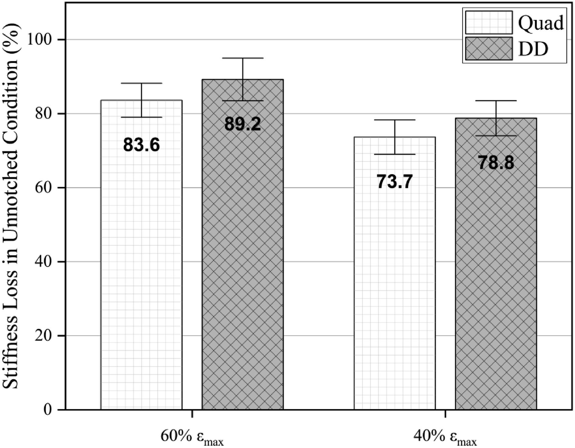
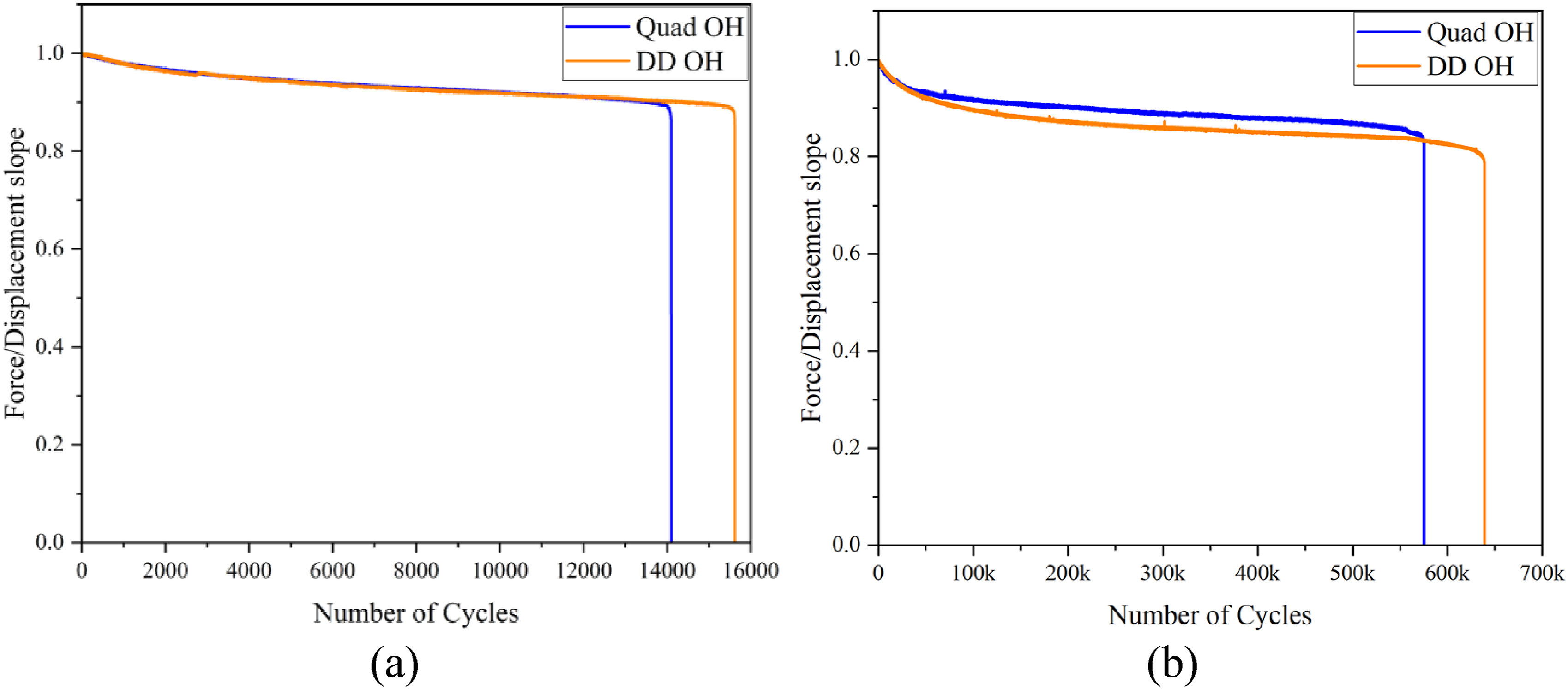
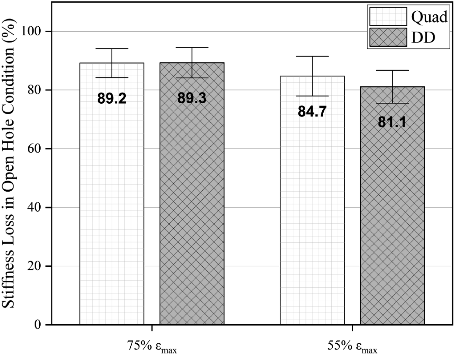
Figure 14 displays the stiffness degradation for fatigue tests in lower and higher cycles for unnotched specimens while Figure 15 shows stiffness at failure for both laminates – Quad and DD. Stiffness loss was found to progress similarly on both laminates, but due to edge effect, the DD laminates failed at a smaller number of cycles. However, for the open hole specimens, the stiffness degradation was similar and the number of cycles to failure were also similar, with an indication of increased number of cycles at failure for the DD (Figures 16 and 17). This loss of dynamic stiffness is indicative of damage initiation, such as transverse matrix cracks and delaminations, and evolution of these damages before final failure of the laminate.
55
Still, the number of cycles to failure was greater for DD laminates, suggesting that the double-double layup configuration may have a potential to produce laminates with better fatigue life. Nevertheless, a thorough comparative study of the mechanisms of damage evolution and damage tolerance of both laminates under cyclic loads is necessary to confirm this hypothesis. Stiffness degradation of unnotched specimens (Quad and DD) at lower and higher strain levels (a) 60% εmax and (b) 40% εmax. Stiffness reduction for unnotched specimens at failure: Quad and DD. Stiffness degradation open hole specimens (Quad and DD) at lower and higher number of cycles (a) 75% εmax and (b) 55% εmax. Stiffness reduction in open hole specimens at failure: Quad and DD.
Conclusions
This study compared static and fatigue performance of two glass/epoxy laminates with the same in-plane stiffness, but with different layup configurations: traditional quadriaxial (Quad) [±45/(0/90)3]s and a double-double (DD) [±15/±75]4T. Results of both static and fatigue tests using unnotched specimens showed that the effect of the stress field near the free edges along the coupon sides caused growth of delamination from the edges, which was more pronounced in DD laminates resulting in early failure. However, when open hole specimens were tested, the results were equivalent for the two types of laminates and less disperse when compared with unnotched specimens. Stiffness degradation during cyclic loading was similar for both laminates (quadriaxial and DD), as shown in force/displacement curves as a function of number of cycles. Furthermore, in both static and dynamic situations, the damaged area was smaller for the DD laminate when compared to the Quad, due to homogenization. In addition, the number of cycles to failure was greater for DD laminates, suggesting that the double-double layup configuration may have a potential to produce laminates with better fatigue life. The DD concept allows homogenization with the use of thin plies and increased repetitions, which has been known to reduce damage size and growth. Hence, as the number of repeats increases, a more significant reduction in damaged area is expected. Although the mechanical properties were not significantly affected by the reduction in damaged area observed for the DD laminates studied, a greater effect is expected for homogenized laminates with a larger number of repeats. Therefore, according to the results presented, DD laminates are interesting candidates as substitute to the traditional Quad laminates for structural applications, with the reported advantages of weight reduction, homogenization, simpler ply drop strategy, efficient optimization using ply angles as a continuous variable, easier manufacturing and repair. However, care must be taken when testing is conducted using standard unnotched coupons, since the DDs will be prone to free edge delamination. These free edge effects can be reduced if notched coupons such as open hole are used for the tests. A detailed study of failure mechanisms including SEM micrographs is necessary to the understanding of the fatigue behavior of these laminates and is planned as future work.
Footnotes
Acknowledgments
The authors would like to also thank Aeris Energy S.A. for manufacturing and providing the laminated plates studied in this research.
Declaration of conflicting interests
The author(s) declared no potential conflicts of interest with respect to the research, authorship, and/or publication of this article.
Funding
The author(s) of the article disclosed receiving financial support for the research, authorship, and/or publication of the article. The work was supported by Coordenação de Aperfeiçoamento de Pessoal de Nível Superior; 0001 and Conselho Nacional de Desenvolvimento Científico e Tecnológico; 301495.
Correction (February 2025):
The Article type has been updated as ‘Article’ along with grammatical errors since its original publication.
Data availability statement
Data sharing not applicable to this article as no datasets were generated or analyzed during the current study.