
Abstract
Composite sandwich structures are widely used in many areas. Light materials, such as honeycomb panels, are usually used as the cores, while stiff materials, such as fiber reinforced polymer laminates, are used as the facesheets. In this work, corrugated cores for sandwich structures were fabricated using carbon fiber reinforced polymers (CFRPs) featuring different stacking orientations. Paper, aluminum, and polypropylene honeycomb cores were also used. Additionally, CFRP was utilized as the facesheets for these sandwich structures. Bending tests, face-wise compression tests (FCT), edgewise compression tests (ECT), and accelerated aging were conducted. Finite element simulations were also performed and compared with experimental results. The results indicated that the corrugated CFRP cores with [0°]5 stacking orientation resulted in the largest flexural stiffness and ECT strength along the flute direction. Conversely, the corrugated cores with [90°]5 stacking orientation resulted in the largest transverse shear rigidity and modulus, FCT modulus and strength, and ECT strength perpendicular to the flute direction. Notably, the sandwich structures using aluminum honeycomb cores were degraded by aging the least. Since sandwich structures can be subjected to the bending load and loads in other directions, this work contributes to selecting core materials and structures of sandwich structures.
Keywords
Introduction
Sandwich structures are widely used in many applications, such as aircraft, wind turbine blades, and building structures. A sandwich structure consists of a lightweight core firmly bonded between two strong facesheets. The core primarily bears the shear load, while the facesheets provide resistance against bending and bear most of the load. 1 Traditionally, polymer foams or honeycombs are used as the core, whereas metal sheets are used as the facesheets. Recently, fiber reinforced polymers (FRPs), such as carbon fiber reinforced polymers (CFRPs), have also been extensively used as facesheets because of their higher specific strengths and stiffness than metals.
Although the core is lightweight, it still bears loads and can affect the strengths of sandwich structures. Meanwhile, besides foam boards, other structures such as I-beams, corrugated structures, and honeycombs can also be used as the cores for reducing weights.
Many works have investigated the mechanical properties of composite materials and sandwich structures.2–8 If the structures are subjected to lower loads, glass fiber reinforced polymers (GFRP) and polymer foam can be used as the core and facesheets, respectively. In comparison, CFRP facesheets and metal honeycomb cores can be ideal choices if subjected to higher loads. 9 When a core has a lower density, shear deformation may result in structural failure, damaging the overall integrity; conversely, a denser and thicker core may lead to facesheet fracture, causing structural failure. 10 Compared to polyurethane foam cores, eco-friendly PET foam cores contributed to a higher ultimate load of sandwich structures (28.01 kN vs 18.27 kN). 11 The adhesive layers between the facesheets and the core also significantly affect the stiffness and failure of sandwich structures. When subjected to a three-point bending test, the maximum normal stresses in the adhesive layers of sandwich beams occurred at the mid-span of the sandwich beam, while the maximum shear stresses occurred at the free edges. 12 When polymers are used in sandwich structures, the degradation of polymers due to aging factors, such as high temperature, humidity, and ultraviolet (UV) exposure, also significantly affects the mechanical properties of sandwich structures. 13
For sandwich structures, firmly bonding the facesheets and the core is critical. Debonding between the facesheets and the core can lead to crack propagation, delamination, and failure. 14 It was reported that the stiffness and strength decrease more when there is a longer debonded region. The compressive strength of impact-damaged composite sandwich structures did not significantly decrease unless the damage covered more than 20% of the structures’ width. 15 Moreover, since a longer debonded region results in more reductions in stiffness, the natural frequencies also decrease significantly; a reduction of 57% was reported when there was a central 80-mm debond in a 200-mm sandwich structure.16,17
The structures of the core can significantly affect the mechanical properties of sandwich structures. 18 For example, optimizing core structures, such as the shapes of honeycombs, can help improve the in-plane compressive strength. 19 The cores can be manufactured from corrugated panels, honeycombs, balsa wood, and cellular polymer foam boards. Since a core separates two facesheets and mainly takes the shear load, it should be lightweight and have a higher shear modulus and strength.
Many works have focused on optimizing sandwich structures, for example, material selections for facesheet FRPs and core shapes, 20 multi-layer sandwich structures, 5 and skin panels. 21 Through finite element analysis (FEA), it was found that the crests of the corrugated cores, which adhere to the facesheets, should have rounded corners to reduce in-plane peeling stress effectively. 22 FEA was also employed to analyze cracked composite structures23,24 and optimize the vibration behaviors of debonded sandwich structures.22,25,26 However, most of these works only optimize part of the structures for particular purposes, which cannot effectively utilize the overall excellent mechanical properties and performance of sandwich structures composed of lightweight cores and high-strength, high-stiffness FRP facesheets.
Although honeycombs or polymer foam boards are lightweight, their low bending stiffness and strength make them unsuitable for manufacturing complex shapes or highly curved structures, limiting the applications of sandwich structures. Moreover, sandwich structures may be deployed in harsh environments, such as offshore wind turbines, where exposure to saltwater can degrade the strength and stiffness of the polymer matrix. These harsh conditions can also accelerate the aging process of polymer foam cores, potentially resulting in structural failure. Given that CFRPs exhibit good resistance to corrosion, 27 this work used CFRPs to fabricate corrugated cores. Bending tests, face-wise compression tests (FCT), and edgewise compression tests (ECT) were conducted. The aim is to investigate the flexural and compressive mechanical characteristics of the sandwich structures employing corrugated CFRP cores with different stacking orientations and honeycomb cores. Both experiments and finite element simulations were conducted. The study also aims to assess the impact of aging on the mechanical properties of these structures by conducting accelerated aging. This work aims to comprehensively study the effects of different core CFRP stacking orientations, core materials, and aging on sandwich structures’ flexural and compressive properties. The findings of this study can contribute to the selection of core materials for sandwich structures based on the loading conditions.
Materials and manufacturing
In this work, the materials of the cores of the sandwich structures comprised corrugated CFRP laminates and paper (PA), aluminum (AL), and polypropylene (PP) honeycomb cores, while the facesheets were CFRP laminates.
A unidirectional (UD) carbon fiber prepreg was used to manufacture the facesheets and corrugated CFRP cores. The prepreg was supplied by Nanpao Resins, Taiwan. The prepreg had a fiber area weight (FAW) of 125 g/m2, a resin content (RC) of 37 wt%, and a thickness of 0.15 mm. The curing process of the prepreg involved heating it to 180°C for 20 min at a pressure of 0.5 MPa.
The adhesive used for bonding the facesheets and the cores was DP-420, a two-component epoxy adhesive manufactured by 3M Company and supplied by SUM-M, Taiwan. This adhesive exhibits an overlap shear strength of 31 MPa and a T-peel strength of 8.76 kN/m at room temperature when used with aluminum substrates.
Since corrugated structures are anisotropic, for the corrugated CFRP cores and the subsequently manufactured sandwich structures, the direction along the flute was defined as 0°, also known as the cross direction (CD). The direction perpendicular to the flute was defined as 90°, also known as the machine direction (MD). The directions are shown in Figure 1(a) and (b). Sketches of (a) directions of corrugated CFRP panels, (b) directions of sandwich structures, and (c) dimensions of corrugated CFRP panels.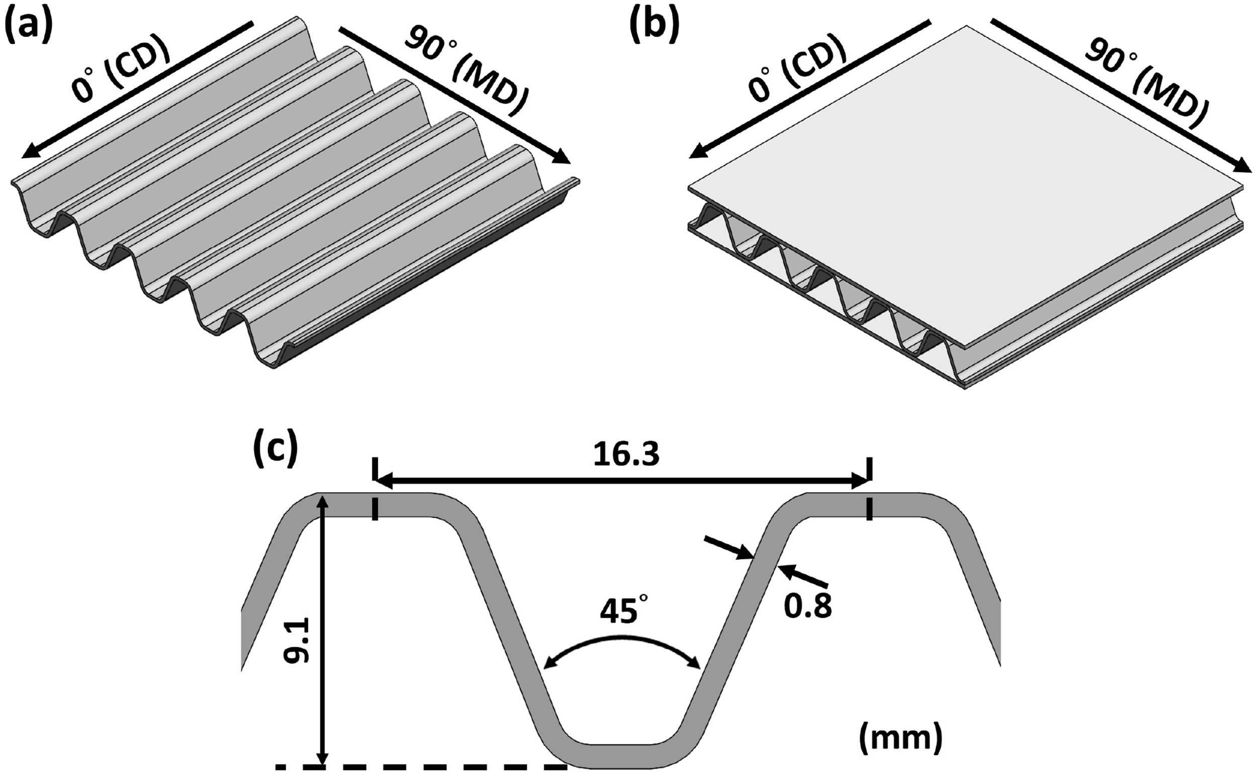
The facesheets of the sandwich structures were manufactured using the UD prepreg with a stacking orientation of [0°/90°/0°/90°/0°/90°/0°]S. The thickness of the facesheet was 2 mm. The corrugated CFRP cores were manufactured using the same prepreg. The stacking orientations of the corrugated cores were [0°]5 (C0), [0°/90°/0°/90°/0°] (C0/9), [90°]5 (C90)), with a laminate thickness of 0.8 mm. The depth of the corrugated CFRP panels was 9.1 mm, with a flute pitch of 16.3 mm. The angle between the bevels was 45°. The dimensions are sketched in Figure 1(c). The laminate fibers had the same orientation definition as the corrugated cores, i.e., 0° of fibers means the fibers were along the flute.
Since honeycomb panels are widely used as the cores of sandwich structures because of their low densities, this work also investigated the effects of various honeycomb cores. The honeycomb cores used in this work included PA honeycomb, AL honeycomb, and PP honeycomb, with a cell size of 9 mm, 9 mm, and 4 mm, and an area density of 300 g/m2, 380 g/m2, and 870 g/m2, respectively. All honeycomb boards have a thickness of 9 mm.
The facesheet CFRP laminates and the cores were manufactured separately and then bonded together using the adhesive to form the sandwich blanks, as shown in Figure 2. A pressure of 0.1 MPa was applied to firmly bond the cores and the facesheets. Subsequently, the sandwich blanks were machined into specimens according to the desired sizes. Sandwich blanks using different cores: (a) Corrugated CFRP, (b) PA honeycomb, (c) AL honeycomb, and (d) PP honeycomb.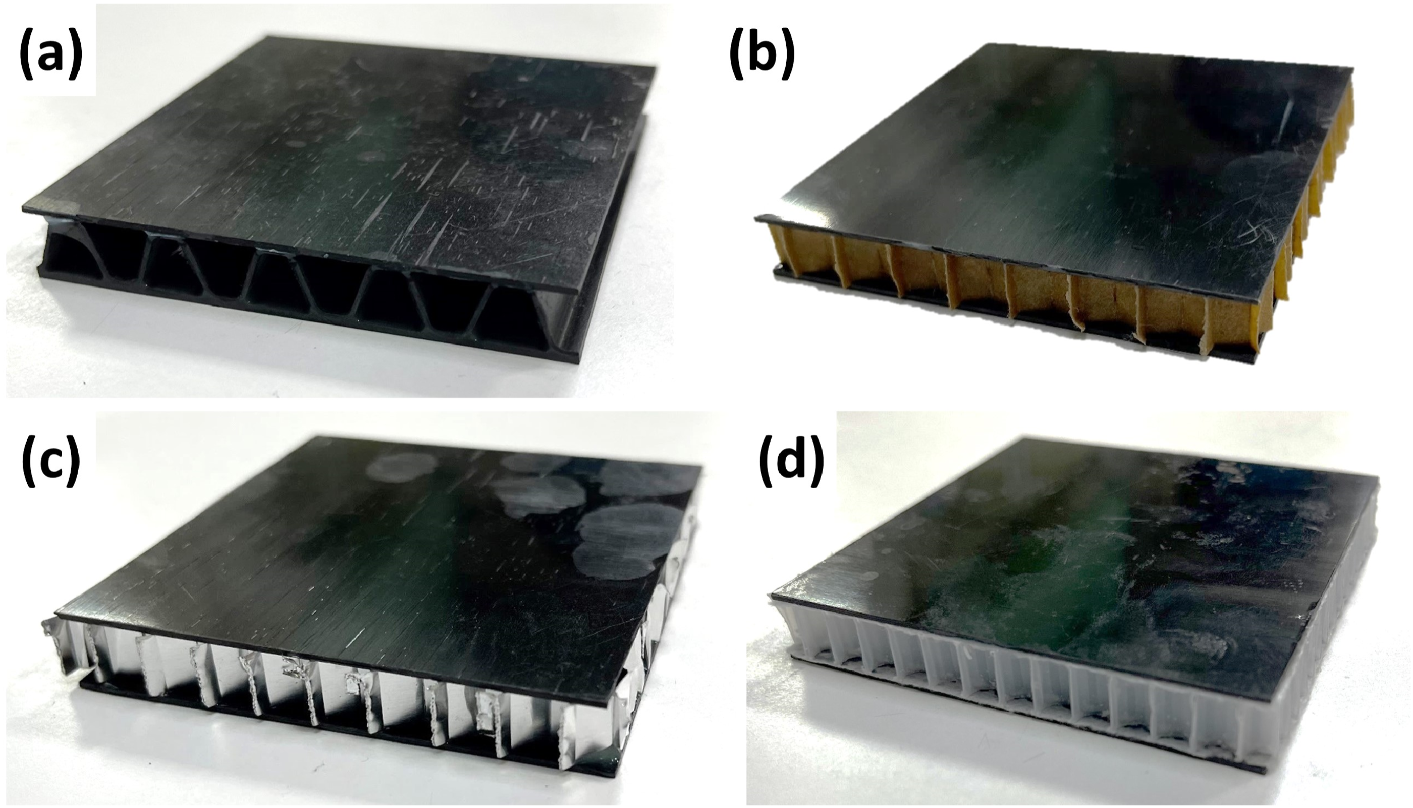
Experiment methods
Bending tests, face-wise compression tests (FCT), edgewise compression tests (ECT), and aging were conducted on the sandwich structures to investigate their mechanical properties and the effects of aging. At least five specimens were tested for each configuration, except in cases where the results showed good consistency, where only four specimens were tested.
Bending tests were performed following the ASTM D7250 standard. A universal testing machine, Yang-Yi QC-H51A2, fitted with a 20 kN load cell was used. The displacement rate was 6 mm/min. Flexural stiffness (D), shear rigidity (U), and core shear modulus (G) were calculated and averaged.
Face-wise compression tests (FCT) and edgewise compression tests (ECT) were conducted on the sandwich specimens following the ASTM C365 standard. The specimens had dimensions of 80 mm in both length and width. The displacement rate was set at 0.5 mm/min. The FCT and ECT setups are illustrated in Figure 3(a) and (b). For FCT, the ultimate compressive strength (F
fcu
) and the compressive modulus (E
fc
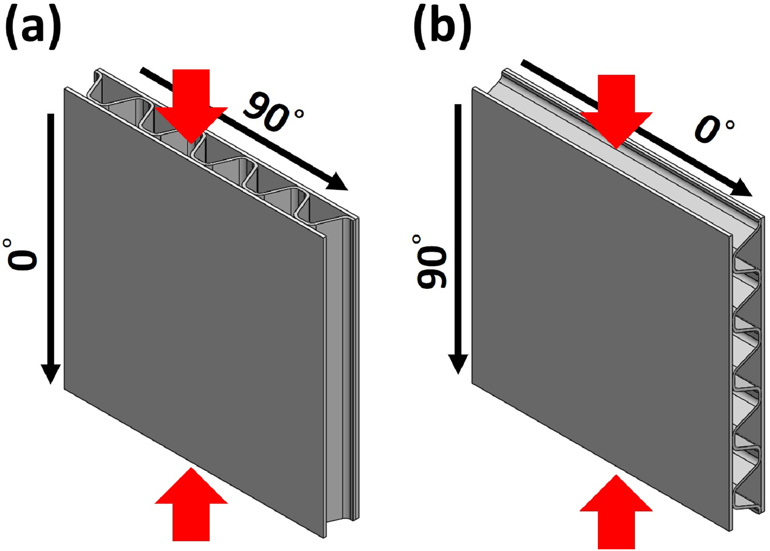
) were calculated. Regarding ECT, because of the anisotropic nature of corrugated structures, two testing directions were considered for the specimens using corrugated CFRP cores: along the flute (0°, known as CD) and perpendicular to the flute (90°, known as MD), as shown in Figure 4. Therefore, two ultimate compressive strengths were determined: Fecu CD and Fecu MD. Test setup: (a) face-wise compression tests (FCT) and (b) edge compression tests (ECT). Directions of ECT conducted on the specimens using corrugated CFRP cores: (a) 0° direction (CD) and (b) 90° direction (MD).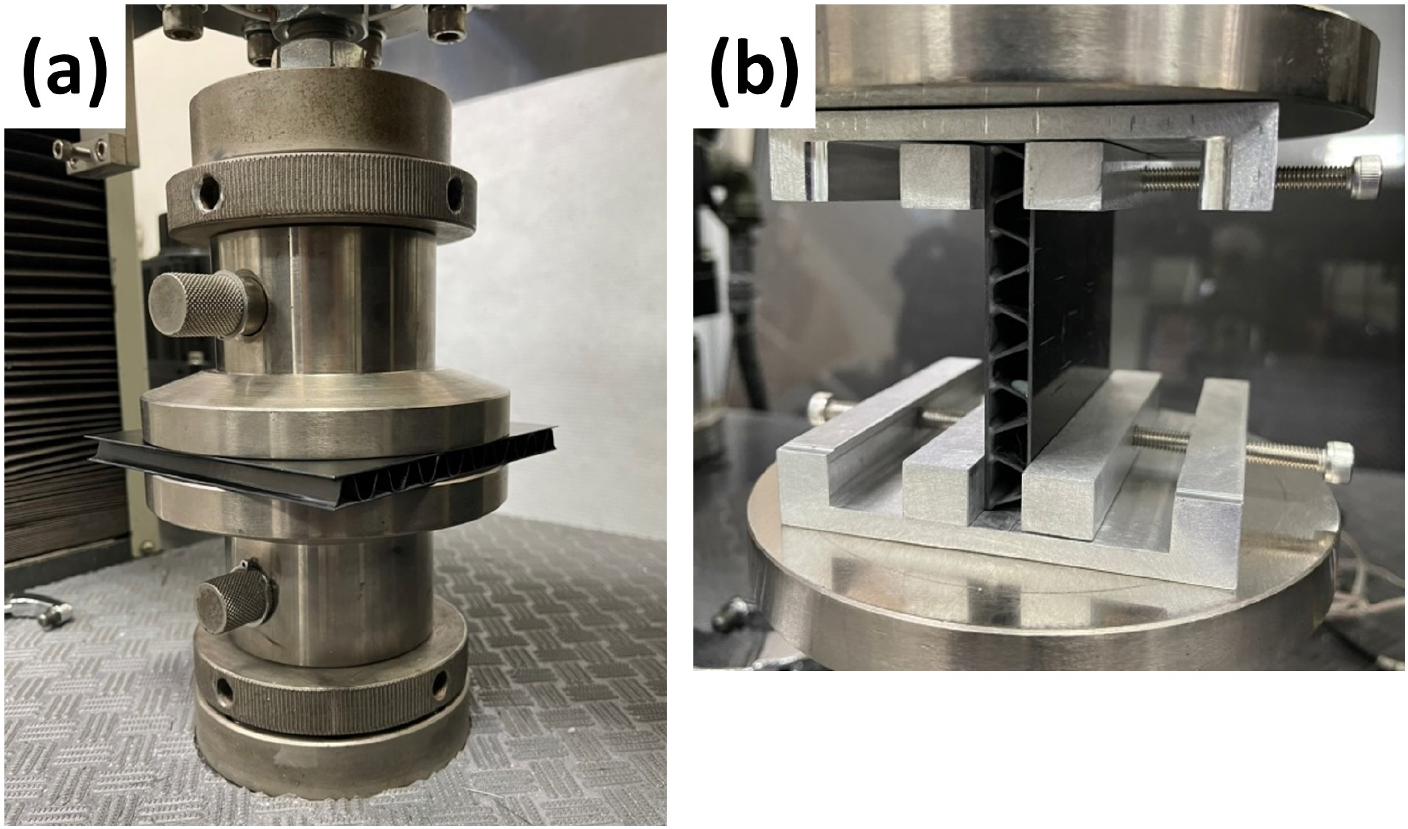
Accelerated aging was also performed on the sandwich specimens using a conditioning chamber. The specimens were aged at 85°C and 85% RH for 168 h (1 week). Subsequently, FCT and ECT were conducted on the aged specimens. The results were compared to those of the unaged specimens. All mechanical tests were performed at ambient room conditions (25°C and 65% RH).
Results and discussion
Bending and shearing properties
Figure 5(a) and (b) show the flexural stiffnesses, transverse shear rigidities, and core shear moduli of the sandwich structures. The flexural stiffness of the sandwich structures using [0°]5 corrugated cores (C0) was 816.27 N·m2, the highest among the results. This was attributed to the carbon fibers of C0 cores being aligned in the 0° direction (i.e., CD), which coincided with the loading direction. Therefore, the 0° fibers provided the highest bending stiffness to the cores, resulting in the highest flexural stiffness of the sandwich structures. In contrast, [90°]5 corrugated cores (C90) resulted in the lowest flexural stiffness (556.94 N·m2) among the sandwich structures using the three types of corrugated cores. This was because the stiff fibers of C90 cores were oriented in 90° direction (i.e., MD) rather than 0° direction (i.e., CD or loading direction). Therefore, the sandwich structures using C90 cores had the lowest flexural stiffness among those using the corrugated CFRP cores. Nevertheless, it was still higher than the flexural stiffnesses of the sandwich structures using the honeycomb cores. For the structures using C0/9 cores, as the fibers of the cores are in both the CD and MD directions, the flexural stiffness falls between that of the structures using C0 and C90 cores. Bending properties: (a) flexural stiffness and (b) transverse shear rigidity and core shear modulus.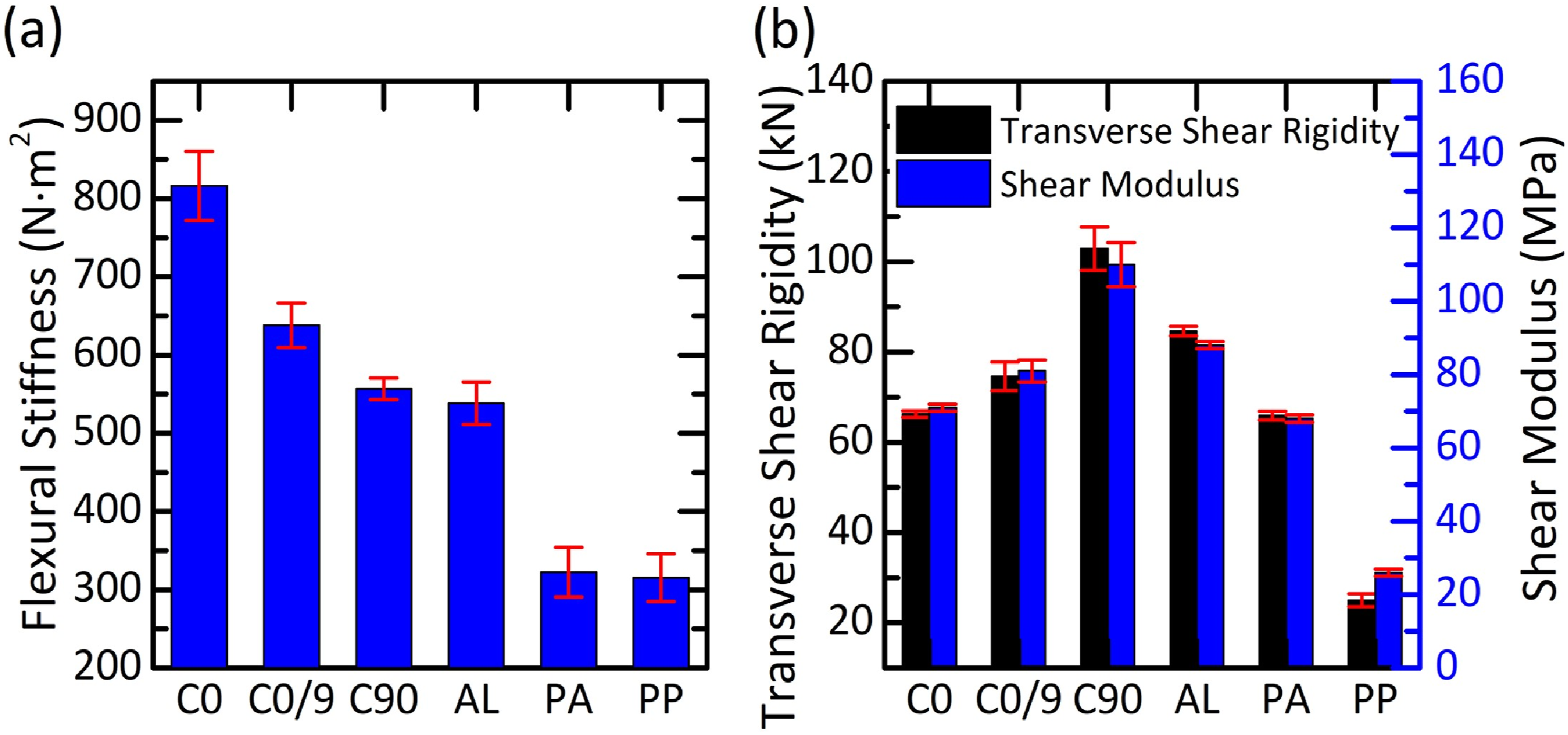
For the shear properties of structures using corrugated CFRP cores, C90 cores resulted in the highest transverse shear rigidity and core shear modulus, 102.93 kN and 110 MPa, respectively, see Figure 5(b). In contrast, C0 cores showed the lowest transverse shear rigidity (66.23 kN) and core shear modulus (71 MPa). This difference arises since the fibers of C90 cores were perpendicular to the loading direction of core shear force, providing the highest resistance against the shear stress resulting from bending, which resulted in the highest transverse shear rigidity and core shear modulus. For C0 cores, since their fibers were parallel to the loading direction of core shear force, the resistance against the shear stress was the lowest. Therefore, the transverse shear rigidity and core shear modulus of the sandwich structures using C0 cores were the lowest among the structures using the corrugated CFRP cores. It was also noted that the transverse shear rigidities and core shear moduli of the sandwich structures using C0 and C0/9 cores were even lower than those of the sandwich structures using AL cores.
Since C0 cores lacked 90° fibers capable of taking shear stress resulting from bending, cracks could generate and propagate along the 0° direction, as shown in Figure 6(a). Conversely, since C90 cores had no 0° fibers that can take normal tensile stress resulting from bending, the cores fractured along the thickness direction, as shown in Figure 6(b). Since C0/9 cores have both 0° and 90° fibers, they show a mixed-mode fracture, as shown in Figure 6(c). Lateral views of bending-tested sandwich structures using (a) C0, (b) C90, (c) C0/9, (d) AL, (e) PA, and (f) PP cores.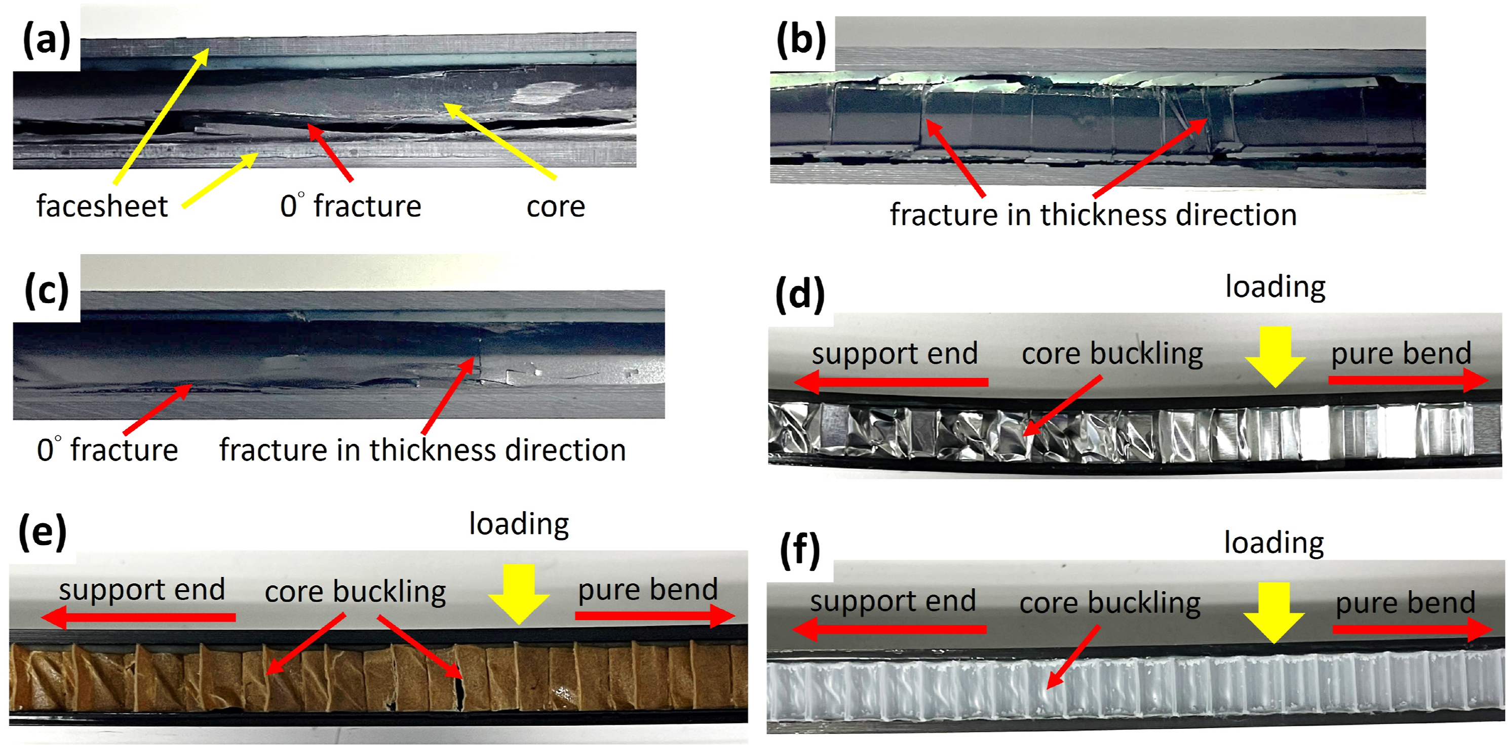
For the structures using the honeycomb cores, AL resulted in the highest flexural stiffness (538.35 N·m2). In comparison, PA and PP resulted in similar flexural stiffnesses (322.57 N·m2 and 315.23 N·m2, respectively), see Figure 5(a). Although AL had a higher area density than PA (380 g/m2 vs 300 g/m2), its flexural stiffness was much larger than PA, resulting in the highest specific flexural stiffness among the sandwich structures using the three honeycomb cores. However, for the structures using PP, although their flexural stiffness was close to the structures using PA, the shear rigidity and modulus were much lower (24994 N vs 65922 N, and 26 MPa vs 68 MPa), see Figure 5(b).
Figure 6(d) to Figure 6(f) show the pictures of the fractured sandwich structures using the honeycomb cores. The structures were tested by four-point bending. In the sections of the cores between the support and the loading points, they experienced extreme shear loading, leading to buckling and core fracture; while in the pure-bending sections, only bending load was present, thus no noticeable damage was observed.
Compared to the sandwich structures with glass fiber reinforced polymer (GFRP) stiffeners (bars) between GFRP facesheets and PVC-foam cores, 28 all the sandwich structures in this work exhibited higher flexural stiffnesses (the lowest was 315.23 N·m2 when PP honeycomb was used) then the reported value (196 N·m2). However, the flexural stiffnesses are still lower than those of the sandwich structures also using GFRP facesheets and PVC-foam cores but designed for marine applications, where the flexural stiffnesses of those sandwich structures were larger than 1000 N·m2. 29
Face-wise compression (FCT) properties
Figure 7 shows the face-wise compressive strengths and moduli of the sandwich structures. C90 cores resulted in the highest FCT strength (20.46 MPa) and modulus (191.89 MPa), while C0 cores resulted in the lowest FCT strength (7.15 MPa) and modulus (117.15 MPa) among the structures using the corrugated CFRP cores. The difference came from the orientation of the fibers. C90 cores had fibers aligned in the MD direction, allowing them to bear more compressive loads normal to the plane, thus resulting in the highest FCT strength and modulus. Conversely, C0 cores, with fibers in the CD direction, could not withstand as much compressive load normal to the plane, leading to lower FCT strength and modulus. As for C0/9 cores, possessing fibers in both the MD and CD directions, they exhibited intermediate FCT strength (12.02 MPa) and modulus (145.31 MPa). Face-wise compressive strength and modulus.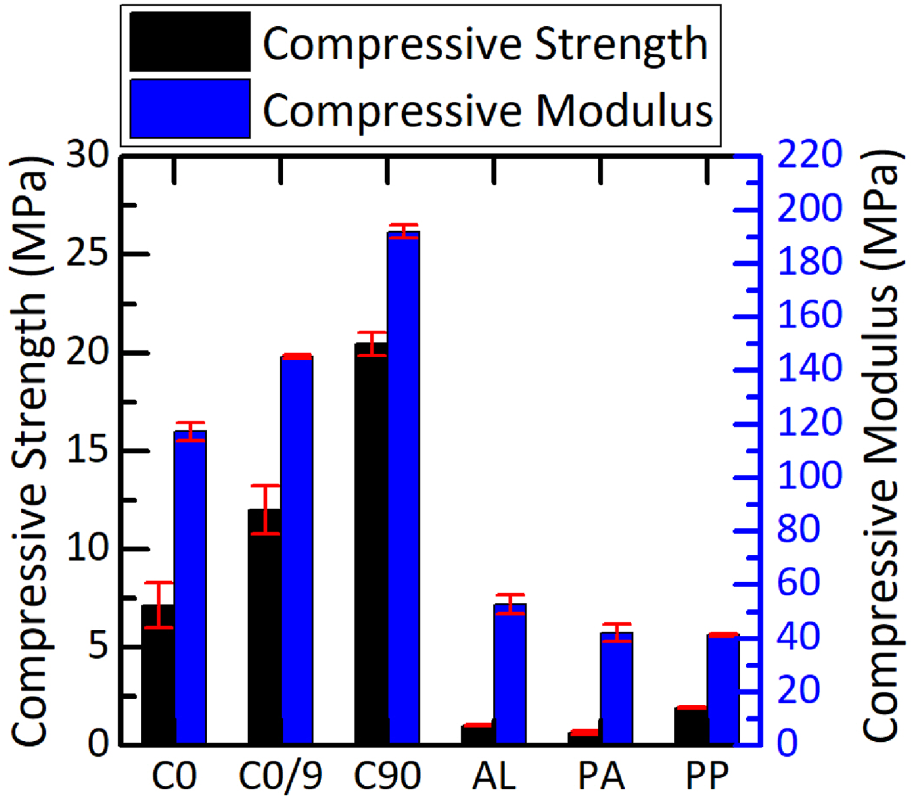
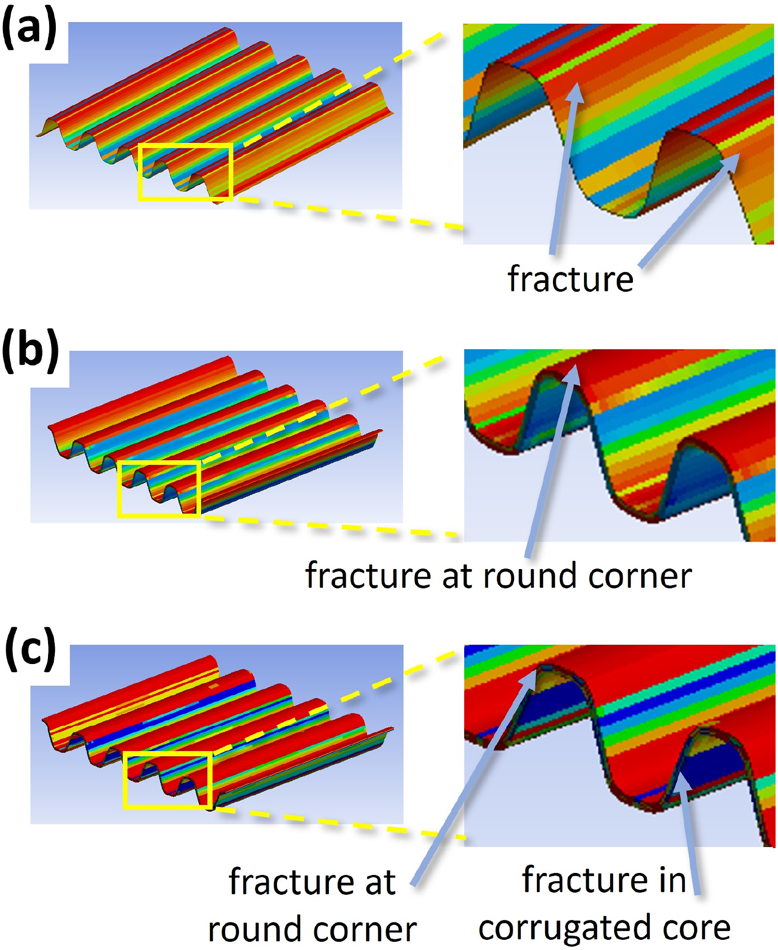
Since C0 cores had a lower resistance against face-wise compression, the primary failure mechanisms of the cores were the fracture of the matrix along the fibers. Figure 8(a) shows that the cracks propagated along the flutes, i.e., the CD direction. Since C90 cores had the highest resistance against face-wise compression, the failure occurred at the round corners adhered to the facesheets due to stress concentrations, as shown in Figure 8(b). As for C0/9 cores, being a combination of C0 and C90 cores, fracture occurred at the round corners and then propagated into the corrugated structures, as shown in Figure 8(c). Lateral views of FCT-tested sandwich structures using (a) C0, (b) C90, (c) C0/9, (d) AL, (e) PA, and (f) PP cores.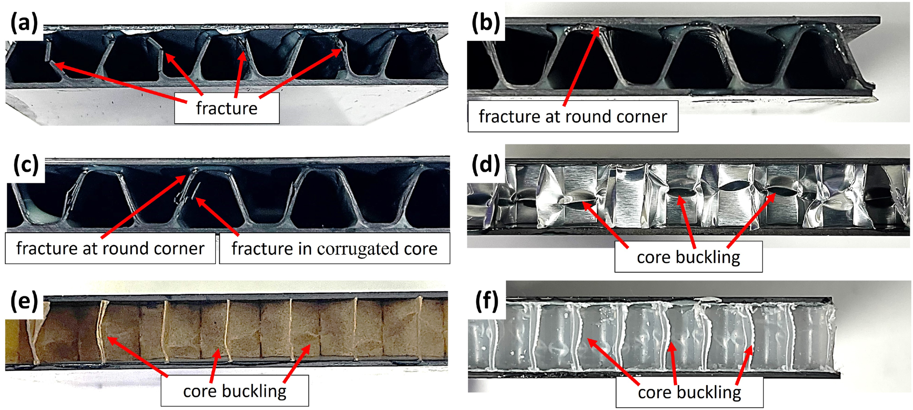
For the honeycomb cores, the FCT strengths of the sandwich structures were 1.04 MPa, 0.67 MPa, and 1.94 MPa for AL, PA, and PP, respectively, while the FCT moduli were 52.73 MPa, 42.15 MPa, and 41.36 MPa, respectively. Therefore, the strength and modulus exhibited different trends, see Figure 7. Regarding the materials themselves, polypropylene’s ultimate strength was lower than aluminum’s. However, since PP cores had a smaller cell size (4 mm), the cell density of PP cores was higher than that of AL and PA cores. Therefore, PP cores could take more compressive load, resulting in a higher FCT strength. On the other hand, concerning the FCT modulus, since aluminum alloy had a significantly higher elastic modulus compared to paper and polypropylene, the FCT modulus of the structures using AL cores was larger than those of the structures using PA and PP cores. The failure mechanism observed in the sandwich structures using the honeycomb cores was the buckling of the cores due to the compressive load normal to the plane, as shown in Figure 8(d) to Figure 8(f).
Compared to the sandwich structures using paper foldcores, 30 the sandwich structures in this work exhibited significantly higher FCT strengths than the reported values. The sandwich structures in this work, which also used paper (PA honeycomb) as the cores, achieved an FCT strength of 0.67 MPa. In contrast, the highest reported FCT strength for the structures using paper fold cores was 0.17 MPa. Additionally, the sandwich structures using AL honeycomb cores showed an FCT strength (1.04 MPa) similar to the reported value (3.50 MPa), which also employed CFRP facesheets and aluminum honeycomb cores. 31
Edgewise compression (ECT) properties
Figure 9 shows the edgewise compressive strengths of the sandwich structures using the different cores. For the sandwich structures using the corrugate CFRP cores, ECT was performed in both the CD (along the flute) and MD (perpendicular to the flute) directions. For ECT along the CD direction, C0 cores yielded the highest ultimate compressive strength (577.92 MPa), while C90 cores yielded the lowest ultimate compressive strength (507.08 MPa). Conversely, for ECT along the MD direction, C0 cores resulted in the lowest ultimate compressive strength (105.08 MPa), whereas C90 cores resulted in the highest ultimate compressive strength (244.33 MPa). As mentioned, the differences came from varying fiber orientations in the corrugate CFRP cores. Edgewise compressive strength.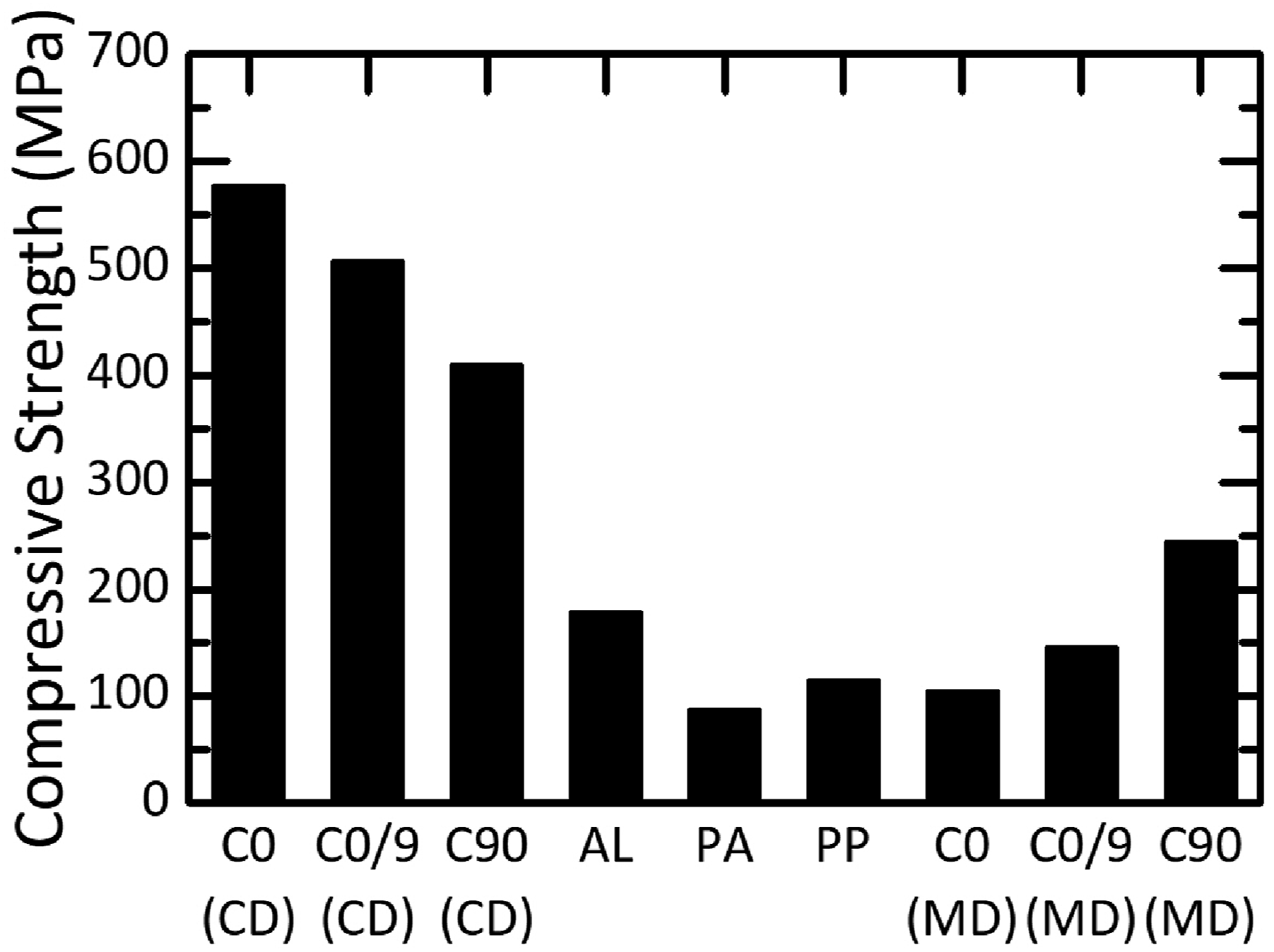
Figure 10(a) to Figure 10(c) show the ECT-tested sandwich structures that were tested along the CD direction. For the structures using C0 cores, since the fibers were oriented to resist compressive loads in the CD direction, the sandwich structures had the highest ECT strength. However, since C0 cores had no fibers in the MD direction, they offered little resistance against lateral expansion perpendicular to the compression direction, leading to buckling and lateral expansion of the structures, as observed in Figure 10(a). Since C90 cores lacked fibers aligned with the compression direction, they fractured perpendicular to the compression direction, as shown in Figure 10(b). It can also be seen that the clamping force applied through the jigs slightly damaged the structures using C90 cores, which can also be seen in Figure 10(b). For C0/9 cores, which had fibers in both the CD and MD directions, no internal core failure was observed. Instead, failure occurs at the base end due to compressive load, resulting in rupturing and delamination, as shown in Figure 10(c). Lateral views of ECT-tested sandwich structures using (a) C0 (CD), (b) C90 (CD), (c) C0/9 (CD), (d) C0 (MD), (e) C90 (MD), (f) C0/9 (MD), (g) AL, (h) PA, and (i) PP cores.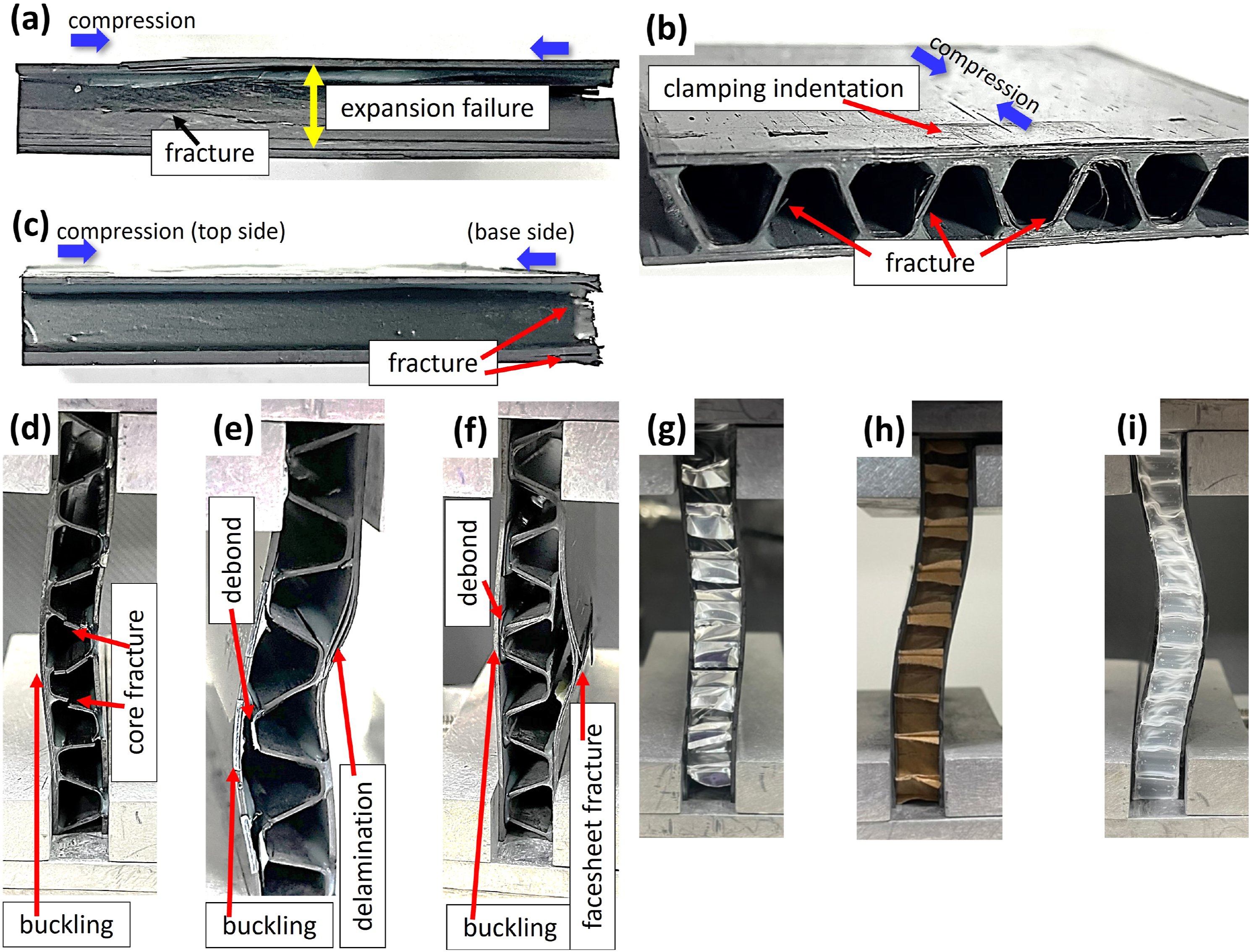
Figure 10(d) to Figure 10(f) show the sandwich structures tested along the MD direction. In all three conditions, buckling occurred due to the compressive load. Since the structures using C0 cores had no fibers in the MD direction, which was also the compression direction, they failed due to core fracture, as shown in Figure 10(d). It was noted that the facesheets of the structures using C0 cores showed no delamination. In contrast, for C90 cores, since their fibers were aligned with the direction of compression, debonding between the core and the facesheets occurred, along with the delamination of facesheets instead of core fracture, as shown in Figure 10(e). Similarly, the structures using C0/9 cores also exhibited core-facesheet debonding, delamination, and fracture of facesheets, as shown in Figure 10(f).
For the structures using the honeycomb cores, the differences in the mechanical properties of the materials led to varying ECT strengths. AL resulted in the highest ECT strength of 178.67 MPa, while PA and PP resulted in ECT strengths of 88.15 MPa and 115.35 MPa, respectively, as shown in Figure 9. The primary failure observed in the structures using the honeycomb cores was the buckling of the structures, see Figure 10(g) to Figure 10(i).
Compared to the sandwich structures using CFRP facesheets and aluminum honeycomb cores, which reported an ECT strength of 610.06 MPa, 31 the sandwich structures in this work, using corrugated C0 cores, showed a similar ECT strength of 577.92 MPa along the CD direction. However, the sandwich structures, also with AL honeycomb cores in this work, only had an ECT strength of 178.67 MPa, significantly lower than the 610.06 MPa value. The difference might be attributed to different CFRP stacking orientations and cell densities of the cores.
Effects of aging
Aging was performed on the sandwich structures at 85°C and 85 %RH for 168 h to simulate long-term use. Following the aging process, FCT and ECT were conducted on the sandwich specimens. The results were then compared to those of the unaged specimens to investigate the effects of aging on the mechanical properties. The differences are shown in Figure 11. Differences between the aged and unaged specimens: (a) FCT strength and modulus. (b) ECT strength.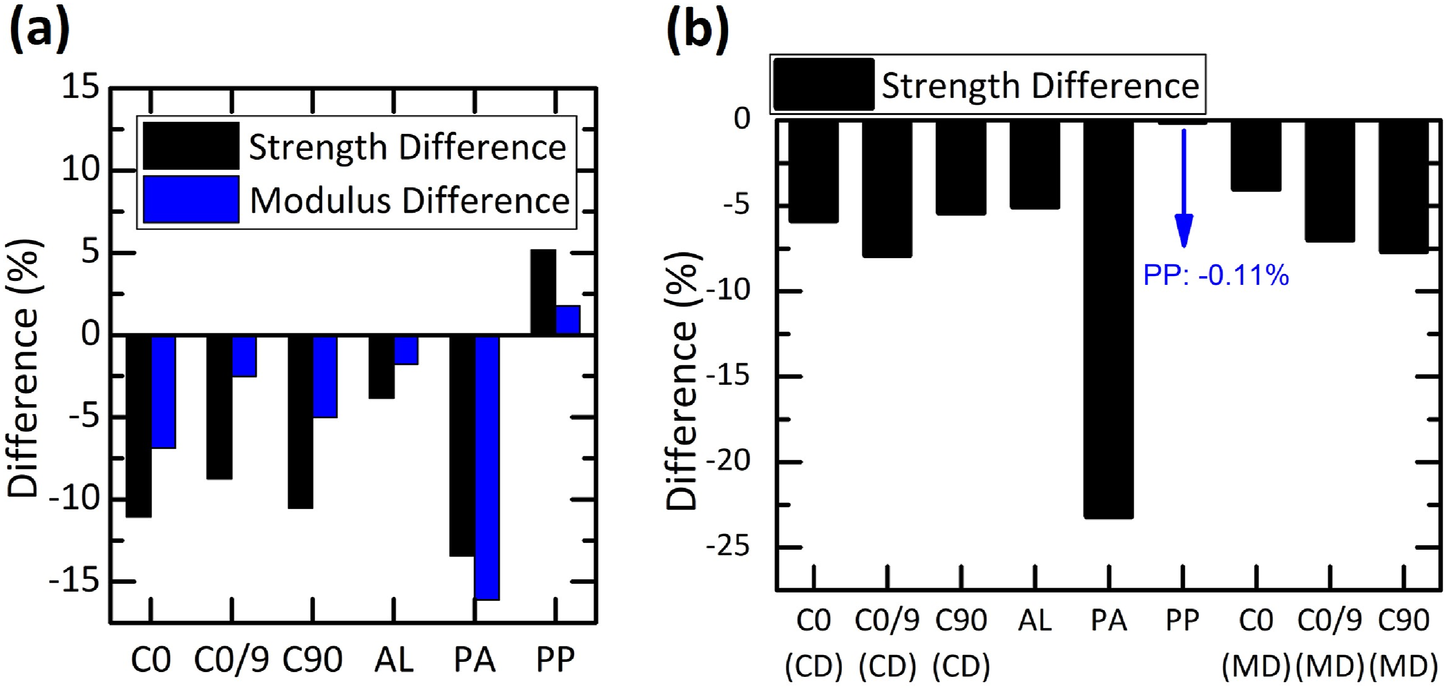
Except for PP cores, all other cores exhibited reductions in FCT strengths, as shown in Figure 11(a), indicating the degradation of the cores caused by the high temperature and humidity during the aging process. The structures using AL cores experienced the most minor reduction in FCT strength, at only 3.85 %, attributed to aluminum alloy’s resistance against such conditions. In contrast, paper-based PA cores resulted in the most significant decrease in FCT strength, at 13.43%, due to their poor resistance against moisture. For the sandwich structures using corrugated CFRP cores, the reductions in FCT strengths ranged from approximately 8.7% to 11.1%.
It was noteworthy that PP cores resulted in an increase of 5.15% in FCT strength, see Figure 11(a). The reason is that the PP honeycombs were manufactured by melting polypropylene, pouring the resin into a mold, and then rapidly cooling down. These processes induced significant temperature and phase changes, resulting in residual stress within the PP honeycombs. During aging, the relatively higher temperatures contributed to the gradual release of this residual stress. Moreover, polypropylene is less sensitive to humidity. The relaxation of residual stress and the resistance against moisture increased the FCT strength of the sandwich structures using PP cores.
The FCT moduli of the aged sandwich structures exhibit the same trend as the FCT strength, as shown in Figure 11(a). AL cores resulted in the most minor reduction (1.79%), whereas PA cores led to the most significant reduction (16.10%). For corrugated CFRP cores, reductions ranged from 2.5% to 6.9%. Additionally, PP cores showed a 1.76% increase, as shown in Figure 11(b). As discussed, these differences came from varying resistance against high temperature and humidity.
The ECT strengths of the aged sandwich structures all experienced reductions, as shown in Figure 11(b). PA cores again resulted in the most significant reduction. The reductions were about the same for corrugated CFRP cores, ranging from about 4.0% to 7.9%, regardless of whether the core fibers’ directions and the tests were in the MD or CD directions. Additionally, it’s worth noting that although the ECT strength of the structures using PP cores decreased, the decrease was minimal, only 0.11%. This further highlights the relatively low degradation of PP cores.
Effects of aging on the adhesive agent
When conducting FCT tests, it was observed that the load-displacement curves showed a smooth region where the load almost remained constant with the displacement, as shown in Figure 12. These regions corresponded to the compression of the adhesive layers, while the subsequent oblique lines indicated compression of the cores. Notably, the curves of the aged sandwich structures showed an extended smooth region (highlighted by the red line in Figure 12), suggesting potential aging of the adhesive agent. This could decrease elastic modulus and strength, resulting in a prolonged smooth region. To investigate whether the adhesive agent underwent aging, tensile tests were conducted on the unaged and aged specimens prepared from the adhesive, DP-420, following the ASTM D638 standard. Load-displacement curves of FCT conducted on the unaged and aged sandwich structures.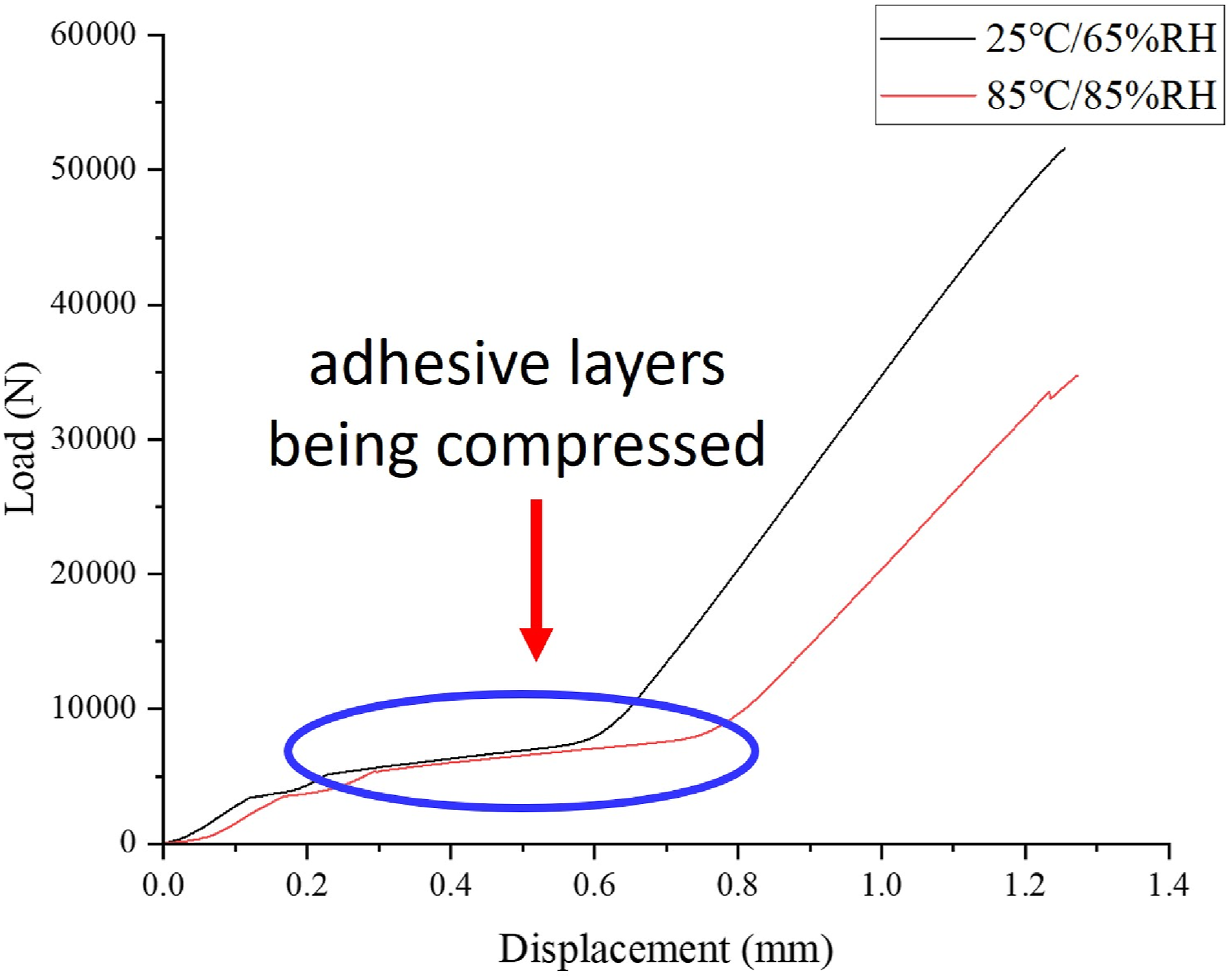
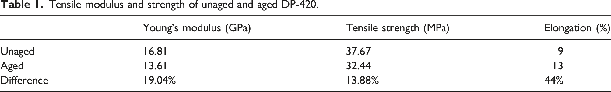
After aging, the tensile specimens of the adhesive showed a deeper yellow color compared to the unaged specimens, see Figure 13, indicating the effects of aging. Table 1 presents the tensile properties of both the unaged and aged specimens. The aged specimens demonstrated reductions in modulus and strength by 19.04% and 13.88%, respectively, while elongation increased by 44%. These results confirm that the adhesive agent underwent aging, resulting in decreased modulus and strength. Consequently, this led to an extended ‘smooth region’ in the load-displacement curves observed during the FCT test. Tensile samples of the adhesive agent: (a) unaged, (b) aged. Tensile modulus and strength of unaged and aged DP-420.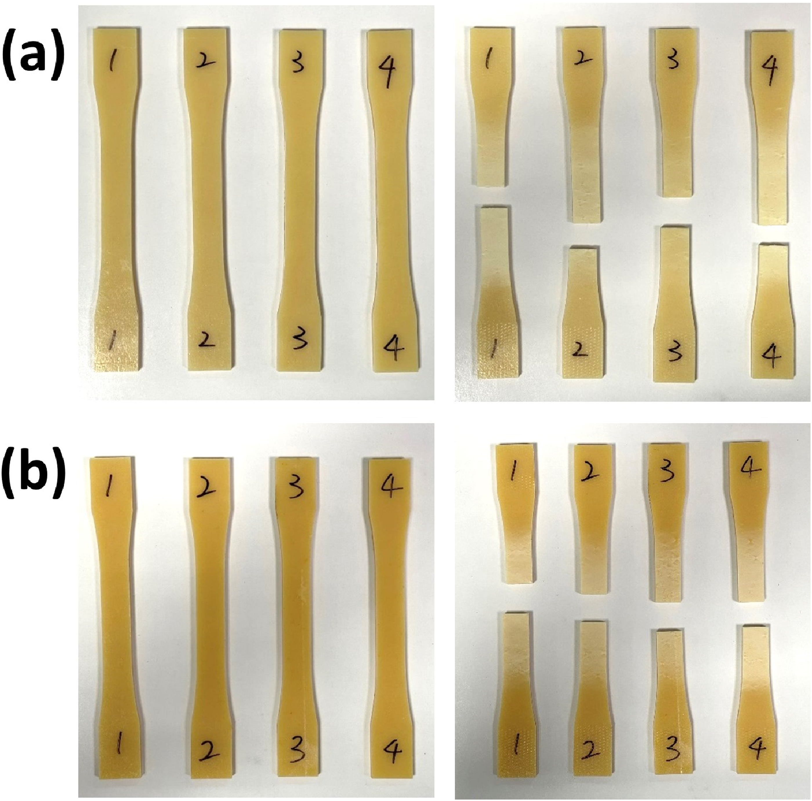
Finite element simulation
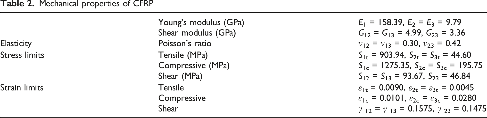
Mechanical properties of CFRP
Experimental and simulation results of bending tests.
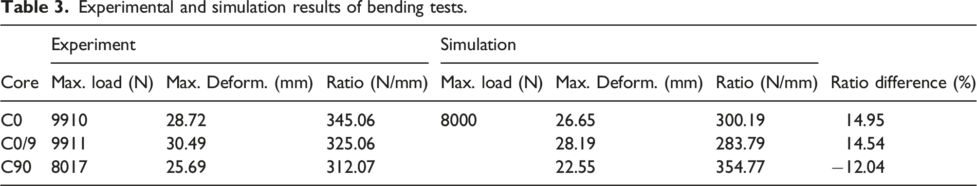
The disparities between experimental and simulated ratios were analyzed to discern consistent trends. For the structures with C0 and C0/9 cores, the experiment-simulation differences averaged around 15%, whereas for structures with C90 cores, the difference was approximately −12.04%. Notably, no definitive trend emerged indicating whether simulated results tended to be larger or smaller than experimental findings. Moreover, the differences were significant.
Several factors could contribute to these significant disparities and lack of a clear trend. Experimental errors resulting from the manufacturing process and experimental setup may play a role, as well as simulation factors, including simulation setting, element type, and mesh density. Variations in measured material properties used as inputs could also influence the results.
It is also noted that for the real structures, the adhesive layers have a thickness and can deform during the tests. While for the models, the adhesive layers are ignored for simplification, which could also contribute to the differences between the experimental and simulation results.
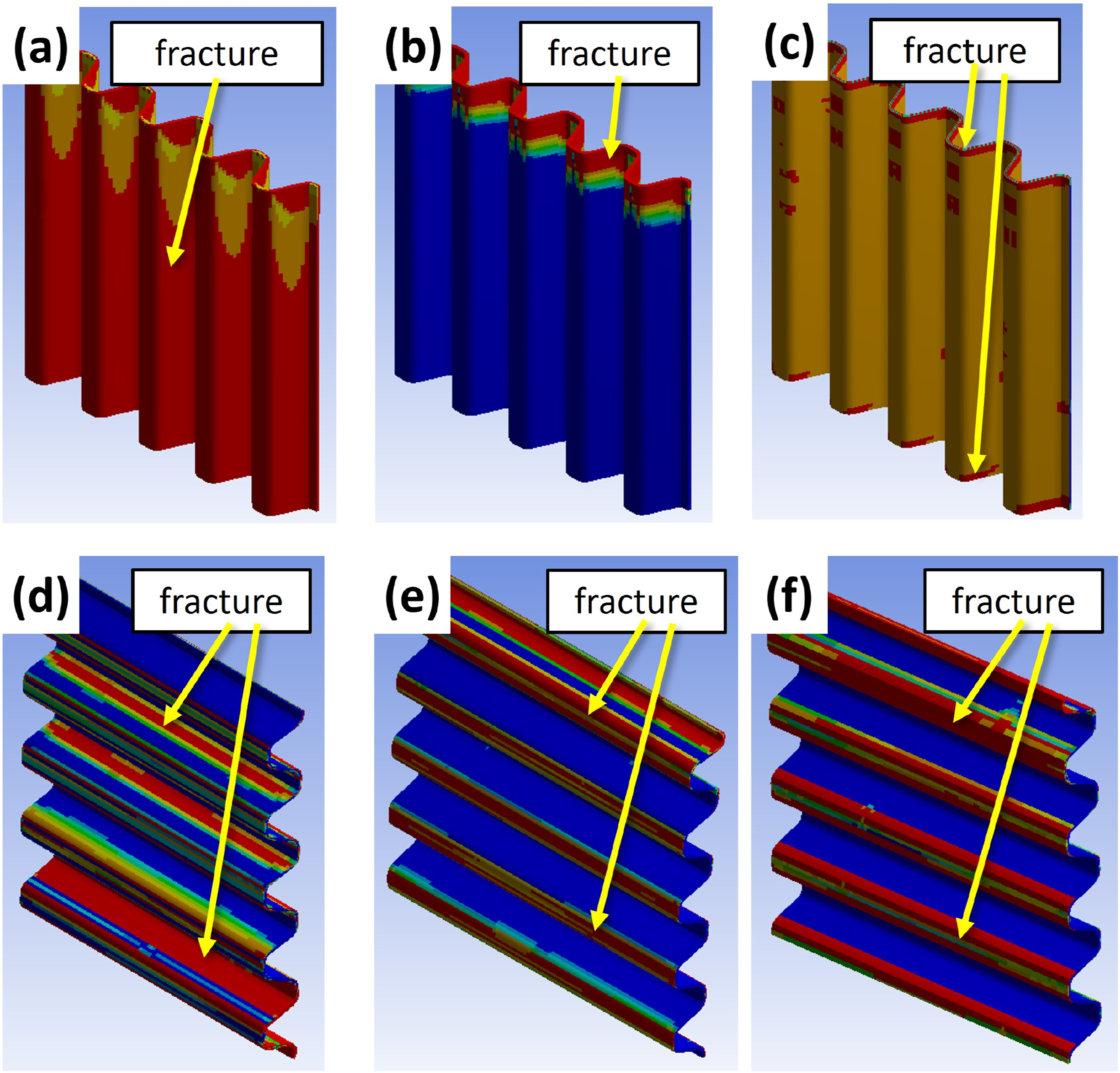
Despite differences between simulated and experimental values, the simulated fracture patterns closely match the experimental observations, as shown in Figure 14, where red regions indicate failure locations. In Figure 14 and the subsequent Figures 15 and 16, the facesheets were hidden to enhance the clarity of the cores. The figures show the results of the Tsai-Wu failure criterion, where the regions in red indicate predicted failure. For C0 cores, simulations revealed core failure occurring primarily due to fracture of the 0° fibers, consistent with experimental findings (see Figure 16(a) and Figure 6(a)). Similarly, simulations for C90 cores showed core failure resulting from fiber fractures along the thickness direction, aligning with experimental observations (see Figure 16(b) and Figure 6(b)). In the case of C0/9 cores, simulations also indicated fracturing along both the thickness and 0° directions, mirroring experimental results (see Figure 16(c) and Figure 6(c)). Simulated fracture patterns of bending-tested sandwich structures using (a) C0, (b) C90, and (c) C0/9 cores. Simulated fracture patterns of FCT-tested sandwich structures using (a) C0, (b) C90, and (c) C0/9 cores. Simulated fracture patterns of ECT-tested sandwich structures using (a) C0 (CD), (b) C90 (CD), (c) C0/9 (CD), (d) C0 (MD), (e) C90 (MD), and (f) C0/9 (MD).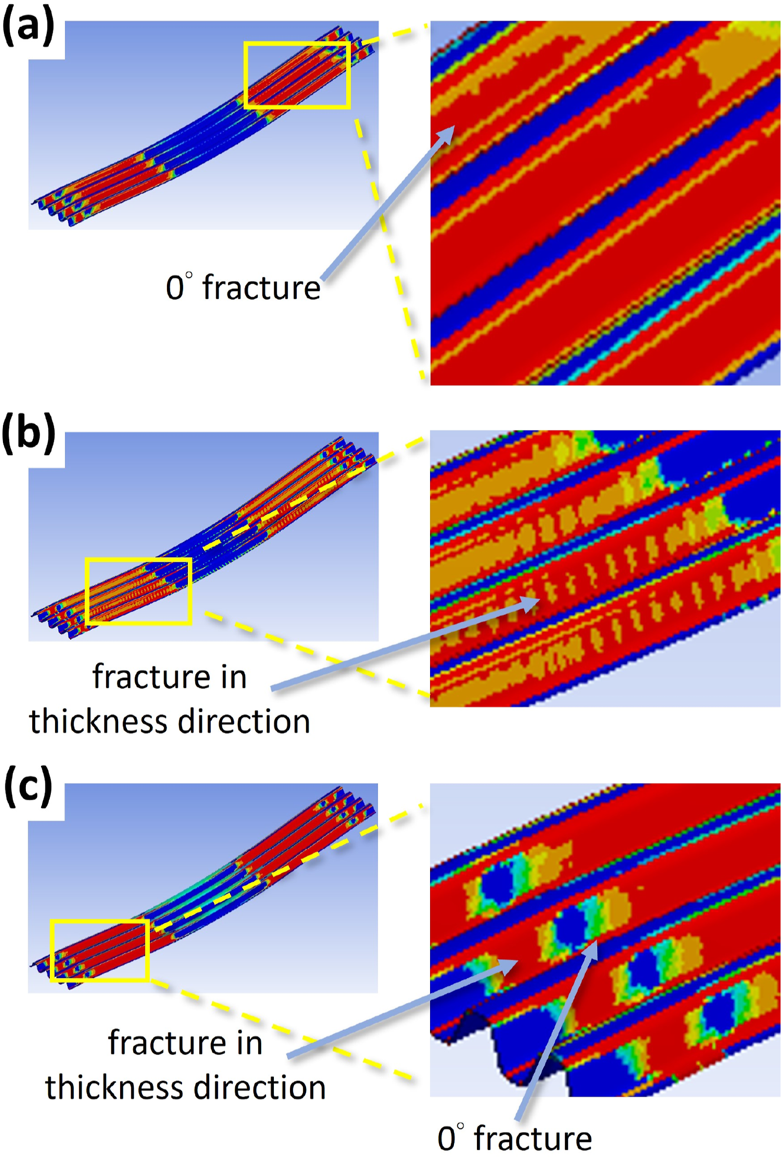
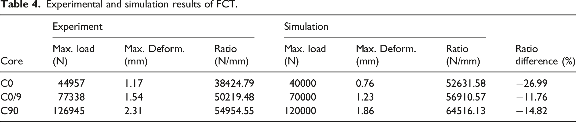
Experimental and simulation results of FCT.
Experimental and simulation results of ECT.
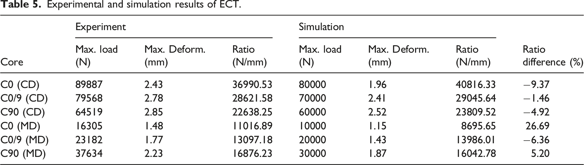
For ECT performed in the MD direction, C0 cores showed fracture along the fiber direction (Figure 16(d) and Figure 10(d)), while for C90 cores, fracture occurred at the round corners adhered to the facesheets (Figure 16e and Figure 10(e)). Similarly, C0/9 cores showed fractures at the regions adhered to the facesheets (Figure 16(f) and Figure 10(f)).
Despite the differences between the simulated maximum forces and deformations and experimental results due to various factors, the simulated failure locations and patterns were consistent with the experimental observations. This indicates that finite element simulation can effectively predict the failure behaviors of sandwich structures using corrugated CFRP cores.
Conclusions
Composite sandwich structures are commonly employed in various applications. This work used CFRP to manufacture the corrugated cores of sandwich structures, while CFRP laminates served as the facesheets. Additionally, different honeycomb cores manufactured from aluminum (AL), paper (PA), and polypropylene (PP) were investigated. The study focused on assessing the flexural, face-wise compressive (FCT), and edgewise compressive (ECT) properties of these structures and examining the influence of aging on these mechanical properties.
The sandwich structures with fibers aligned along the flute direction (C0 cores) showed the highest flexural stiffness and cross-direction compressive strength. Conversely, the structures with fibers perpendicular to the flute direction (C90 cores) exhibited superior transverse shear rigidity and shear modulus, FCT compressive strength, and compressive strength in the machine direction. Finite element simulations closely matched experimental results, confirming their predictive accuracy for failure modes in corrugated-core sandwich structures.
When exposed to aging, the structures with AL cores demonstrated minimal reductions in FCT strength and modulus, which can be attributed to aluminum alloy’s superior temperature and humidity resistance compared to paper and epoxy polymer. In contrast, the structures using PP cores showed increased FCT strength and modulus, with minimal reduction in edgewise compressive (ECT) strength, as aging facilitated the release of residual stress within the PP cores.
This work discussed the effects of corrugated core fiber orientations, different honeycomb cores, and aging on the flexural and compressive properties of sandwich structures, aiding in core material selection for composite sandwich structures. Future work could involve refining finite element simulations for improved accuracy and investigating additional aging conditions, such as salt spray tests, given the application of sandwich structures in offshore wind turbines.
Footnotes
Acknowledgments
The authors would like to thank the NSTC, Taiwan, for supporting this research under contracts No. 112-2221-E-992-082 and No. 112-2221-E-110-058.
Declaration of conflicting interests
The author(s) declared no potential conflicts of interest with respect to the research, authorship, and/or publication of this article.
Funding
The author(s) disclosed receipt of the following financial support for the research, authorship, and/or publication of this article: The authors would like to thank the NSTC, Taiwan, for supporting this research under contracts No. 112-2221-E-992-082 and No. 112-2221-E-110-058.
Data availability statement
The raw/processed data required to reproduce these findings cannot be shared at this time as the data also form part of an ongoing study.