






Abstract
Thin–walled specimens are widely used in various applications, such as automotive bumper, buildings, bridges and warehouse shelve. Investigation of a reinforcement composite coating on sides of thin–walled metal specimens can be valuable, based on their collapse behavior. This article performs an experimental study to investigate energy absorption characteristics of hybrid aluminum/composite specimens of thin–walled cross–section under quasi–static lateral loading; and also, to optimize them by the Taguchi method. To achieve the goals, experimental specimens are manufactured in three different groups. Some thin–walled aluminum specimens are produced by the extrusion and tested as simple specimens or the benchmark (the first group). Then, as the second group, each vertical edge of some aluminum specimens is reinforced by a composite coating. Four different glass fibers and two different resins are used to produce the hybrid specimens. Each specimen of the second group is reinforced by a certain fiber type and with 1, 3, or 5 layer numbers; and their crashworthiness properties are measured during the flattening tests. Effects of fiber types and layer numbers of the composite stiffener are investigated on crushing behavior of the hybrid samples. Their results illustrate that hybrid metal/composite specimens with a 5–layer stiffener has the best performance. Therefore, as the third group, design of experiments is performed by the Taguchi method and several optimized hybrid specimens are introduced as the main output of the optimization process. Results illustrate that total absorbed energy of some reinforced specimens are 6.21 times of the corresponding value of the benchmark.
Keywords
Introduction
Dissipation or absorption of the kinetic energy has always been one of the most important topics in the industrial fields, especially in the transportation vehicles. Researchers of this field are looking for suitable ways to improve crashworthiness and energy absorption performance of structures that are exposed to crushing and impact loadings. Using light foam fillers into hollow specimens are a suitable method to enhance energy absorption capacity of thin–walled structures. As another approach, reinforcing the thin–walled columns and tubes by composite laminates and producing the hybrid metal–composite specimens can be suggested. In some applications, metal–composite composition may achieve better crashworthiness performance in comparison with the separated metal and composite samples.
Niknejad and Rahmani 1 carried out experimental and theoretical studies on lateral compression process of empty and foam–filled hexagonal columns. Yan et al. 2 investigated lateral crushing of empty and polyurethane foam–filled composite tubes. Baroutaji et al. 3 optimized energy absorbers in the form of sandwich tubes under lateral loading. Rouzegar et al. 4 discussed influences of geometrical discontinuities on lateral crushing and energy absorption of tubular structures. Zohrabi et al. 5 introduced a new approach to increase energy absorption capability of thin–walled sections during the flattening process. Khanchehzar et al. 6 discussed effects of different internal stiffeners on energy absorption behavior of square sections during the quasi–static flattening progress. Niknejad and Orojloo 7 introduced a new nested system of tubes with special cross–section as the lateral energy absorber. Liu et al. 8 developed experimental and theoretical analyses of lateral crushing of aluminum foam–filled circular tubes. Niknejad et al. 9 introduced folded quadrangular columns under the lateral loading as a novel energy absorber.
Tran 10 investigated crushing behavior of multi–cell thin–walled triangular tubes under lateral loading by the theoretical method. Liu et al. 11 studied on lateral crushing and bending of square tubes made of carbon fiber reinforced polymer (CFRP) filled with aluminum honeycomb. Zhu et al. 12 discussed energy absorption of metal, composite and hybrid metal/composite structures under oblique crushing loading. Lou et al. 13 investigated lateral crushing of hierarchical quadrangular thin–walled tubular structures. Firouzi et al. 14 optimized H–shaped thin–walled energy absorbers by Taguchi method and derived a theoretical equation to estimate their energy absorption. Yang et al. 15 recommended an internally nested circular–elliptical tube system for lateral energy absorption. Saadatfard et al. 16 derived a general theory to predict absorbed energy by bending and plastic hinge line phenomena during indentation and flattening processes. Shams et al. 17 suggested some preformed circular tubes with various geometrical shapes as the energy absorbed during the quasi–static flattening process by numerical and experimental analyses. Sun et al. 18 discussed crashworthiness and optimization of hybrid CFRP/aluminum structures under the transverse loading. Liu et al. 19 performed an experimental analysis to investigate energy absorption behavior of circular carbon/epoxy composite tubes under quasi–static and dynamic loading. Prabhakar et al. 20 presented an overview of burst, buckling, durability and corrosion analysis of lightweight fiber reinforced polymer (FRP) composite pipes and their applicability.
Dhaliwal and Newaz 21 discussed flexural behavior of hat sectioned aluminum/carbon fiber reinforced mixed material composite beam by experimental and numerical methods. Zhang et al. 22 axially compressed hybrid square CFRP/aluminum tubes through both of experimental and numerical methods and discussed their energy absorption performance. Sun et al. 23 performed a comparative study on aluminum/GFRP/CFRP tubes subjected to oblique lateral loading. Isaac and Ezekwem 24 presented a review of crashworthiness performance of energy absorbing composite structures within the context of materials, manufacturing and maintenance for sustainability. Ghasemi et al. 25 performed a multi–objective optimization on thin–walled circular tubes with combined bar extrusion under quasi–static axial loading, based on their energy absorption properties. Li et al. 26 studied on lateral compression of circular aluminum, carbon FRP and glass FRP tubes. Zhao et al. 27 investigated lateral crushing of a new carbon fiber/epoxy composite bidirectional self–locked thin–walled tubular structure. Kahraman and Akdikmen 28 experimentally studied on deformation behavior and energy absorption capability of nested steel tubes under lateral loading. Huang et al. 29 performed a comparative study on crashworthiness of hybrid aluminum/CFRP beams under quasi–static and dynamic bending. Xiao et al. 30 investigated failure modes and energy absorption mechanism of CFRP Thin–walled square beams filled with aluminum honeycomb under dynamic impact.
Thin–walled square specimens are used in various applications, such as cross–beams of automotive bumper, some buildings, bridges and warehouse shelve. The present article introduces a reinforcer composite coating on the thin–walled square beam sides to investigate its influences on their crashworthiness behavior, as a current research gap. On the other hand, a review of previous articles led to the idea of experimental investigation of energy absorption performance of hybrid metal–composite sections under the quasi–static lateral loading. To achieve the mentioned goal, firstly, some thin–walled square aluminum specimens are produced by the extrusion method as simple specimens (benchmark) and laterally crushed between two rigid platens and their energy absorption capacity is considered as the benchmark value. Secondly, two vertical edges of some simple square specimens are reinforced with composite laminates of 4 various glass fibers and 2 different resins to manufacture the hybrid aluminum/composite specimens by the hand layup method; and their energy absorption properties are examined to compare with the corresponding values of the benchmark. In the third step, optimization process of the hybrid specimens is performed by the Taguchi method; and based on their energy absorption characteristics and plastic deformation modes, several optimized specimens are suggested as suitable energy absorbers.
Manufacture of experimental specimens
A thin–walled square aluminum column was selected as initial metal specimens with Young’s modulus, yield strength, ultimate strength and strain hardening exponent of 69 GPa, 172.8 MPa, 194.4 MPa and 0.17, respectively. External dimension of its square cross–section is 35 × 35 mm with a homogenous wall thickness of 2.0 mm. The square columns were produced by the traditional extrusion method with an initial length of 6 m. Then, by performing the cutting process on the initial square aluminum columns, using a rotary saw machine, simple specimens of 50 mm length were prepared as shown in Figure 1. Three similar simple specimens were selected as the benchmarks. The simple aluminum specimen of square cross–section (benchmark).
To produce hybrid specimens, 4 different types of glass fibers were prepared, as reported in Table 1. Two types of resin were used to produce composite coatings of various hybrid specimens, as the following: • Vinylester resin, based on bisphenol A (with code 301). • Polyester resin, based on isophthalic acid (with code 211). Different types of the used fibers and their codes.

Both resins are produced by Farapol Jam company, in Iran. The above mentioned fibers and resins were used to manufacture hybrid composite/aluminum specimens.
In this research work, 3 different groups of experimental specimens were produced as the following: • • •
In the first group, 3 simple aluminum specimens with the same characteristics were prepared, tested and used as the benchmark; and its energy absorption performance parameters were selected as the benchmarks and criteria for evaluating the corresponding performance of the experimental specimens of the second and third groups.
Trends of manufacturing process of the experiment samples of the second and third groups are the same, and layer numbers and layer configurations of the produced samples of Group 2 and 3 are the only differences between them. In various specimens of the second group, a composite coating with 1, 3 and 5 layer numbers of the same type of fibers were used to produce the hybrid samples. In each experimental specimen of the second group, types of the used fibers (layer) in different layers of a hybrid sample is the same; However, in different samples of this group, fiber types may be different. In other words, in a series of hybrid samples of the second group, the specimens were manufactured with the same 1, 3 and 5 layers of chopped strand mat fibers, while in another series of hybrid samples of the mentioned group, the specimens were produced with the same 1, 3 and 5 layers of 2D woven fibers. The recent trend was repeated for the multi–axial (3D) woven fibers and combo mat fibers, in the other series of the second group specimens. Figure 2 shows a hybrid composite/aluminum specimen of Group 2 or 3, schematically. A hybrid composite/aluminum specimen of Group 2 or 3, schematically.
To manufacture the hybrid samples of Group 2, a strip of the desired fibers was prepared with a width equal to the internal height of the vertical sides of the aluminum column (35-2 × 2 = 31 mm) and with the desired length. Then, resin impregnated fiber strip was twisted around one of the vertical sides of the aluminum column, continuously; to manufacture a composite laminate coating with 1, 3 or 5 layers around the mentioned vertical edge, by hand layup method. The similar trend was performed for the other vertical edge, too. Therefore, after the fabrication process, there is a composite laminate of 1, 3 or 5 layers on each side of each vertical edge. Fiber types of all layers of a certain sample of the second group are the same; therefore, to prepare the composite coating of each vertical edge of a specimen of Group 2, length of the initial fiber strip was selected slightly more than the results of layer numbers × the column length (50 mm) × 2 (two sides of a vertical side).
Characteristics of the experiment specimens of the second group.

In the top 3–7th columns, 1, 2, 3 and 4 indicate the multi axial (3D) woven fibers, chopped strand mat fibers, combo mat fibers, and 2D woven fibers, respectively.
In the specimen code, the numerical part indicates layer numbers of composite coating; and in its alphabetical part, MA, CSM, CM and W indicate multi axial (3D) woven fibers, chopped strand mat fibers, combo mat fibers and 2D woven fibers, respectively.
The production process of the experimental specimens of the third group was similar to the corresponding trend of the specimens of the second group, but, there were the following three differences between them: 1. Layer numbers of the composite coating on each vertical edge of all samples of the third group was the same and selected equal to 5 layers. 2. Fiber types of different layers of a certain specimen of the third group could be selected different from its other layers or same to its other layers. 3. Two different types of resins were used to produce various specimens of the third group.
The designed experiments by the Taguchi optimization method for the third group specimens and their results.

In the top 3nd column, 1 indicates Vinylester resin and 2 means Polyester resin.
In the top 4–8th columns, 1, 2, 3 and 4 indicate the multi axial (3D) woven fibers, chopped strand mat fibers, combo mat fibers, and 2D woven fibers, respectively.
In the table, SEA, TAE, and SNR indicate specific energy absorption, total absorbed energy, and signal–to–noise ratio, respectively.

An experimental hybrid specimen of the third group, before the test.
Flattening tests
Flattening tests were performed on the specimens of the three experimental groups. For this purpose, simple and hybrid specimens were placed between two rigid platens of a DMG Universal testing machine, Model 7166. The hybrid specimens were placed inside the machine in such a way that their two reinforced edges were parallel to the loading direction (It means that two reinforced edges were not in contact with the two rigid platens). It is clear that the recent consideration was not necessary for the simple specimens (benchmark) due to their diagonal symmetry. All the experiments were carried out under the quasi–static conditions with a constant loading rate of 10 mm/min. Experimental observations illustrate that at commencement of the test, the applied compression force on the specimens begin to increase from zero to reach an initial peak load, with a steep slope. Then, the downward trend of the curve is usually followed, which is sometimes accompanied by fluctuations. The test was continued until quasi–rigid behavior was observed. The maximum lateral force of the initial part of the force–displacement diagram is called initial peak load (IPL). During each test, diagram of lateral force was sketched in terms of lateral displacement.
By sketching the load–displacement diagram for each test and calculating the area under the recent curve, total absorbed energy (TAE) of the tested specimen is obtained. Then, specific energy absorption (SEA) of a specimen is calculated by dividing its total absorbed energy into the specimen mass. Average force is determined by dividing the total absorbed energy into ultimate displacement. Crash force efficiency (CFE) is obtained by calculating the ratio of average force to the initial peak load, and its value is always between 0 and 1, and its ideal value is equal to unit.
In the optimization section (Group 3), total absorbed energy (TAE), specific energy absorption (SEA) and crash force efficiency (CFE) were considered as the objective functions. For all 3 objective functions, a higher value of signal–to–noise ratio (SNR) is better quality characteristic. Results of the performed tests on the third group specimens (optimization process) were analyzed by Minitab software. Table 3 reports values of total absorbed energy, specific energy absorption, and their corresponding signal–to–noise ratios for each specimens of Group 3.
Results and discussions
Figure 4 illustrates force–displacement diagram of a hybrid sample of the second group, which its each vertical edge was reinforced by the same 3 layers of combo mat fibers and Vinylester resin (3-CM). The mentioned test was repeated 2 times, on two completely similar specimens. Similar variation trends of two curves and small differences between them in most parts of the curves affirm the accuracy and repeatability of the performed experiments in the second group. Load–displacement diagram of a hybrid specimen of the second group with three combo mat/Vinylester layers (3-CM).
Similarly, Figure 5 shows lateral load–displacement diagram of a hybrid specimen of the third group which its each vertical edge was reinforced by 5 different layer types of [combo/2D woven /chopped strand mat2/2D woven]. The recent diagram is belonged to the test number 28 of the designed experiments by the Taguchi method (Table 3), which was twice repeated. Load–displacement diagram of a hybrid specimen of the third group with 5 layers of [combo/2D woven/chopped strand mat2/2D woven].
Hybrid specimens with different layer numbers (Group 2)
In this section, results of the performed flattening tests on the hybrid specimens of the second group are discussed and their results are also compared with the corresponding results of the simple sample (first group, benchmark). In the second group, in each sample, fiber types of all the composite coating layers of the mentioned sample were selected the same, and then, some specimens with the same fiber type, but with different layer numbers were produced and tested. In other words, in the second group, the hybrid specimens with 1, 3 and 5 layers of multi axial (3D) woven fibers, the samples with 1, 3 and 5 layers of chopped strand mat fibers, the specimens with 1, 3 and 5 layers of combo mat fibers and the hybrid samples with 1, 3 and 5 layers of 2D woven fibers were fabricated and tested. For each specimen of the second group, two similar samples were prepared and tested to investigate repeatability of the experiments; and average value of the obtained total absorbed energies of each pair specimen (of the repeated tests) was obtained. The same trends were performed for specific energy absorption and crash force efficiency of the repeated tests. Figure 6 compares total absorbed energy values of all the experimental specimens of the second group. Similarly, their specific energy absorptions and crash force efficiencies are illustrated in Figures 7 and 8, respectively. Specifications of these specimens were previously reported in Table 2. Comparison of total absorbed energy (TAE) by the specimens of the second group. Comparison of specific energy absorption (SEA) by the specimens of the second group. Comparison of crash force efficiency (CFE) of the specimens of the second group.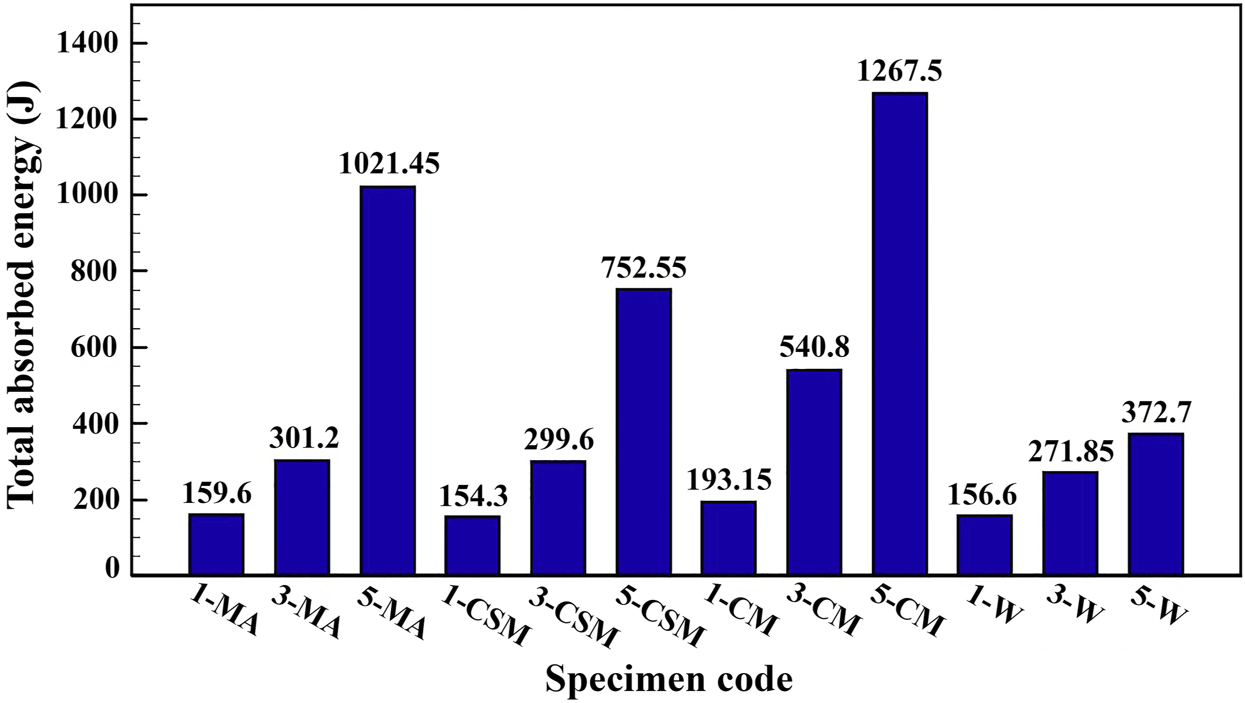


The performed experiments on the simple samples of the first group (benchmark) show that total absorbed energy and specific energy absorption of a simple aluminum sample with cross–sectional dimensions of 35 × 35 × 2 mm and length of 50 mm are equal to 204.1 J and 6520 J/kg. In addition, crash force efficiency of the benchmark during the flattening test is 0.29. Comparison of the reported results in Figure 6 and the corresponding results of the benchmark shows that total absorbed energy of all 4 different specimens reinforced by a composite lamina (single–layer) made of one of the four fiber types is less than the corresponding value of the benchmark. This is physically justified as follows. Thickening the vertical edges of the square cross–section of the hybrid structure leads to a reduction in the ultimate displacement; and decrement of the ultimate displacement of the reinforced specimen by a single–layer respect to the simple sample (benchmark) decreases its total absorbed energy capacity, comparing with the benchmark. However, the recent sequence is not observed in the hybrid specimens with 3–layer and 5–layer coatings. In other words, in the reinforced specimens with 3 or 5 layers of one of the 4 fiber types, total absorbed energy of the hybrid samples is higher than the corresponding value of the benchmark. As a quantitative comparison, total absorbed energy of the reinforced samples with 3 or 5 similar layers of multi axial (3D) woven fibers, chopped strand mat fibers, combo mat fibers and 2D woven fibers are 1.48–5.00, 1.47–3.69, 2.65–6.21 and 1.33–1.83 times of the corresponding value of the benchmark. It means that, when total absorbed energy capacity of thin–walled square sections is the first priority of the design, reinforcing the vertical edges of the aluminum section with 3 or 5–layer composite laminate is very useful and can increase energy absorption capacity of the specimen up to 521%. However, using a single–layer composite coating isn’t appropriate as a reinforcement, based on TAE.
By increasing the layer numbers of the composite coating, mass of the hybrid structure enhances; therefore, comparison of the reported SEAs in Figure 7 and the corresponding value of the benchmark shows that specific energy absorption of all 4 different reinforced specimens with a single–layer composite made of one of 4 fiber types is less than the corresponding value of the benchmark. In addition, specific energy absorptions by 3 different hybrid samples reinforced with 3 similar layers of multi axial (3D) woven fibers, chopped strand mat fibers or 2D woven fibers are less than the corresponding value of the benchmark; and only in the reinforced specimen with 3 similar layers of combo mat fibers, specific energy absorption of the mentioned hybrid sample is 1.28 times of the corresponding value of the benchmark. This indicates that increment percentage of total absorbed energy capacity of the reinforced specimens with 3 or 5 layers made of the same fiber type due to the reinforcing is less than the increment percentage of mass of the structures due to the reinforcing. However, the recent trend isn’t observed in the hybrid specimens of the 5–layer coating. On the other hand, specific energy absorptions by the reinforced specimens with 5 similar layers of multi axial (3D) fibers, chopped strand mat fibers, combo mat fibers and 2D woven fibers are 2.13, 1.83, 2.16 and 1.01 times of the SEA value of the benchmark. It means that, when specific energy absorption of thin–walled square sections and mass of the structure are the main priorities of the design, reinforcing the vertical edges of aluminum specimens with 5–layer composite coating is useful and can increase its specific energy absorption up to 116%; but, in the most cases, using 1 or 3 layers of the composite coating as the reinforcement isn’t suggested.
Crash force efficiency is another parameter to evaluate energy absorption performance of different structures, and its larger value and closer to 1 is better. When crash force efficiency of an energy absorber of a vehicle increases, the maximum transmitted load to occupants of the vehicle decreases, for a certain energy absorption capacity. Results of the experimental specimens of the first group show that CFE of benchmark sample is equal to 0.29. Therefore, comparison of the reported results in Figure 8 and the CFE of the benchmark shows that, in viewpoint of crash force efficiency, the performance of all the reinforced specimens with a composite lamina (single–layer) is weaker than the benchmark; however, performance of all the reinforced specimens with a 5–layer composite coating is much better than the benchmark, based on the CFE parameter. In the cases of reinforced specimens with 3 similar layers, the conclusion depends on type of used fibers, and in the reinforced specimens with 3 similar layers of 2D woven or combo mat fibers, crash force efficiency increases, whereas, in the reinforced specimens with 3 similar layers of multi axial (3D) woven or chopped strand mat fibers, crash force efficiency remains constant, in comparison with the benchmark.
In the following, regardless of the simple sample (benchmark), energy absorption performance of the second group specimens is compared with each other. The sketched results in Figures 6–8 illustrate that in the specimens of the second group reinforced by a composite coating of 1, 3 or 5 layers of the same type of multi axial (3D) woven fibers, chopped strand mat fibers, combo mat fibers or 2D woven fibers, by increasing the layer numbers of composite coating, total absorbed energy, specific energy absorption and crash force efficiency increase; and always the performance of a hybrid thin–walled section reinforced by 5 identical layers, is the best; and performance of a hybrid thin–walled section reinforced with single–layer is the worst (among the tested hybrid specimens). In total, among all the reinforced samples by 1, 3 or 5 layers of identical fibers, the highest total absorbed energy, specific energy absorption and crash force efficiency belong to the thin–walled hybrid specimen of aluminum/composite with 5 identical layers of combo mat fibers twisted around its vertical edges, and values of the mentioned parameters of this suitable specimen are 1267.5 J, 14067 J/kg and 0.65, respectively. The second priority is given to the reinforced specimen with 5 identical layers of multi axial (3D) woven fibers and its corresponding parameters are equal to 1021.45 J, 13907 J/kg and 0.53. Reviewing of the previous published works demonstrates that achievement of specific energy absorption by a hollow thin–wall section during the flattening process up to 14000 J/kg is a very desirable result. For example, Khanchehzar et al. 6 carried out influences of different internal stiffeners on energy absorption behavior of square sections during the flattening process. In their research, aluminum sections with dimensions of 34.4 × 34.4 and a length of 40 mm, which were reinforced by blades with a thickness of 1.25 mm, have been subjected to lateral load. Their results showed that SEA by 26 different reinforced specimens is between 2950 to 7758 J/kg, 6 while specific energy absorption by the aluminum/composite hybrid samples of the present research work is 14179 J/kg. Liu et al. 11 studied lateral crushing and bending responses of CFRP square tube filled with aluminum honeycomb. Their reported results illustrated that specific energy absorption (SEA) of hollow sections is equal to 3730 J/kg; while, the corresponding value of the filled sections is equal to 11620 J/kg 11 ; consequently, specific energy absorption by the aluminum/composite hybrid samples of the present article is 1.22 times higher than their specimens. Kahraman and Akdikmen 28 performed an experimental study on deformation behavior and energy absorption capability of nested steel tubes under lateral loading. Their experiments were carried out on nested tube samples in which a minimum of 2 and a maximum of 6 tubes were used together in different numbers and sequences. Their results illustrated that specific energy absorption of the nested samples are equal to 2050 to 8480 J/kg; However, specific energy absorption of the hybrid samples of the present study is 1.67 times higher than their maximum results.
Overall, the reported results in this section demonstrate that, when reinforcing process of thin–walled aluminum sections is performed by one type of fibers, using the combo mat fibers for both the 3 and 5–layer composite coating is recommended, based on total absorbed energy, specific energy absorption and crash force efficiency; and in the absence of combo mat fibers or due to the economic considerations, using the multi axial (3D) woven fibers is suggested as the second priority (especially, in the case of the 5–layer composite coating). However, in the hybrid specimens with a single–layer composite coating, type of fibers doesn’t have a significant effect on total absorbed energy, specific energy absorption and crash force efficiency, and in this case, fiber type of the single–layer can be selected only based on the economic considerations (chopped strand mat or 2D woven fibers).
In this section, several hybrid specimens were fabricated with 7–layer composite coating and tested, which their results illustrate that due to thickening and excessive stiffness of the vertical edges of the reinforced square column, plastic deformation mode of the specimens changed from flattening to general buckling (Euler); consequently, total absorbed energy capacity of the structure showed a severe reduction. Therefore, in this section, the maximum layer number of the composite coating was selected equal to 5; and in the next section of the present study, optimization process of the reinforced specimens with 5–layer composite coating is performed.
Optimization of hybrid specimens with 5 layers of various fibers
Experiment analysis performed in the previous section (the second group), as a preliminary analysis demonstrated that the best energy absorption performance occurs when a 5–layer composite coating is used. Therefore, in this section, the hybrid thin–walled specimen of aluminum/5–layer composite coating is optimized by Taguchi method. Optimization process is performed, based on the following three different objective functions: • Total absorbed energy; • Specific energy absorption; • Crash force efficiency.
Optimization process based on total absorbed energy
Figure 9 illustrates effects of 6 different parameters (fiber types of each layer of composite coating and resin type) on total absorbed energy of the thin–walled metal/composite sections. In the figure, total absorbed energy has been considered as the objective function. The mentioned results were obtained from the performed optimization process by Taguchi method. In the optimization analysis, 2 types of resin and 4 different types of fibers have been used. The reported results in the recent figure shows that, based on total absorbed energy, the manufactured specimens with the Vinylester resin have better performance, comparing with the produced specimens with the Polyester resin. Thus, using the Vinylester resin is recommended to produce the Taguchi’s optimum sample. Also, in all layers, using the combo mat fibers leads to the highest amount of total absorbed energy; and also, for each of the 5 layers, using the multi axial (3D) woven fibers, chopped strand mat fibers and 2D woven fibers is in the next priorities, respectively. Effect of each control factor on total absorbed energy of the third group specimens.
Response of signal–to–noise ratio of each level of the control factors (objective function: TAE).


Contribution percentage of each control factor on the TAE.
Based on the optimization results and by considering the total absorbed energy parameter as the objective function, a hybrid structure with 5–layer composite coating of combo mat/Vinylester is introduced as the optimal sample. To verify and calculate the amount of total absorbed energy of the optimum structure, 2 identical samples with optimal specifications (5 layers of combo mat fiber/Vinylester resin) were produced and tested. Their load–displacement curves are sketched in Figure 11. From the recent experiment, total absorbed energy capacity of the mentioned optimal structure was measured equal to 1267.5 J. In some engineering applications, where energy absorbers are used in stationary structures, total absorbed energy capacity is usually the main design priority, and in the cases, where energy absorbers are used in moving structures, specific energy absorption is usually the main design priority. Therefore, in the recent part, an independent optimization process was performed, based on total absorbed energy of the hybrid structure, and in the next part, an independent optimization process is performed, based on specific energy absorption of the hybrid structure. Load–displacement diagram of the optimized specimen, based on the TAE objective function.
Optimization process based on specific energy absorption
In this part, specific energy absorption is selected as the objective function of Taguchi optimization method. Figure 12 shows effect of each control factor on specific energy absorption of hybrid specimens, and Table 5 reports response of signal–to–noise ratio of each level of the control factors. The results demonstrated that when specific energy absorption is selected as the objective function, similar to the previous optimization process, using the Vinylester resin results in the best performance. In addition, using the multi axial (3D) woven fibers in the first and the third layers, combo mat fibers in the second and the fifth layers and the chopped strand mat fibers in the fourth layer, leads to the optimal specimen, based on achieving the maximum amount of specific energy absorption. Based on the application viewpoint, Figure 12 illustrates that variations of the SNRs due to using the multi axial (3D) woven fibers, chopped strand mat or combo mat fibers respectively, in the second, third and the fourth layers are less than the other layers; Therefore, in these three intermediate layers, using the multi axial (3D) woven fibers, chopped strand mat or combo mat fibers doesn’t cause considerable changes in the amount of specific energy absorption of the hybrid structure. Therefore, due to the lower price of chopped strand mat fibers, when specific energy absorption of the hybrid structure is only the main design criterion, using the chopped strand mat fibers is recommended for 3 intermediate layers and it is economically viable. However, when, both of the specific energy absorption and total absorbed energy capacity of the hybrid structure is the main design parameters, using the combo mat fibers in the three intermediate layers is suggested. Effect of each control factor on specific energy absorption of the third group specimens. Response of signal–to–noise ratio of each level of the control factors (objective function: SEA).

Considering the different effects of control factors on specific energy absorption of the hybrid structure, contribution percentage of each control factor on the objective function (SEA) is illustrated in Figure 13. The figure demonstrate that resin type has the most effect (26.6%) and the fiber types in the fifth layer has the least effect (11.8%) on the amount of specific energy absorption by the hybrid structure. The significant effect of the resin type on the specific energy absorption for the metal–composite hybrid section can be physically justified as follows. When specific energy absorption is considered as the objective function, both the total absorbed energy capacity and density (weight) of the composite coating affect the SEA. Therefore, due to higher density of the resin respect to the fibers, resin type has more effects on the objective function (SEA), comparing with the fiber type. Contribution percentage of each control factor on the SEA.
The recent optimization process performed by considering the specific energy absorption as the objective function illustrates that a hybrid structure with the 5–layer composite coating of the Vinylester resin and the multi axial (3D) woven fibers in the first and the third layers, combo mat fibers in the second and the fifth layers, and the chopped strand mat fibers in the fourth layer, is the optimized specimen of this part. To verify and determine specific energy absorption of the mentioned optimized structure, two identical optimal samples were produced and tested. Their load–displacement curves is sketched in Figure 14. Specific energy absorption of the recent optimal structure was obtained equal to 14179 J/kg, by the experimental method. Load–displacement diagram of the optimized specimen, based on the SEA objective function.
Optimization process based on crash force efficiency
In this part, crash force efficiency is considered as the objective function in the Taguchi optimization process. Figure 15 shows effect of each control factor on crash force efficiency of aluminum/composite samples, and Table 6 reports response of signal–to–noise ratio of each level of the control factors. Based on the objective function of crash force efficiency, using the Polyester resin results in better performance, in comparison with the made specimen by the Vinylester resin. In addition, the results demonstrate that using the 2D woven fibers in the first layer and combo mat fibers in the second to fifth layers, introduces the optimal hybrid specimens, based on crash force efficiency. Effect of each control factor on crash force efficiency of the third group specimens. Response of signal–to–noise ratio of each level of the control factors (objective function: CFE).

Figure 16 compares contribution percentage of each control factor on the objective function (CFE). The figure shows that fiber types in the first layer has the most effect (31.6) and resin type has the least effect (7.6) on the crash force efficiency. Since the crash force efficiency depends on the mean load and the initial peak load, the significant effect of the first layer on the objective function (comparing with the other 5 factors) demonstrates that fiber types in the first layer has the considerable influences on the bond quality between the composite coating and aluminum section; and the quality of the mentioned bonding has significant effects on the initial peak load. However, the low effectiveness of the resin type on the objective function (CFE) can be justified as the following. In a composite structure, fibers sustain the main part of the applied load on the structure and the resin withstands the remaining part of the applied load; and the main task of the resin is to keep the fibers in their original place and also to transfer force between the fibers. Therefore, changing the resin type has less effects on the initial peak value (comparing with the other 5 control factors). Contribution percentage of each control factor on the CFE.
Results of the performed optimization based on the objective function of CFE demonstrate that a hybrid aluminum/composite specimen made of the Polyester resin, 2D woven fibers in the first layer and the combo mat fibers in the 4 next layers, is the optimized specimen of this part. Then, 2 similar optimal specimens with the above specifications were produced and subjected to lateral flattening test. Their lateral load–displacement curves are obtained according to Figure 17. Crash force efficiency of the recent optimal structure was measured equal to 0.85, while its specific energy absorption and total absorbed energy were measured equal to was 13139 J/kg and 1063.6 J, respectively. Load–displacement diagram of the optimized specimen, based on the CFE objective function.
Totally, three independent optimization analyzes were performed in the present research and 3 optimal samples were introduced to achieve the highest values of the various objective functions of total absorbed energy, specific energy absorption or crash force efficiency. Therefore, each of these three optimal samples can be used in various applications and by considering the different objective function of the design.
Conclusion
Energy absorption characteristics of the hybrid aluminum/composite specimens of thin–walled cross–section during the quasi–static flattening process were investigated in the present research work and their results were compared with the corresponding values of the simple aluminum specimens (as the benchmark). Three groups of the experimental specimens were produced, consist of simple aluminum specimen (the first group), hybrid specimens with different layer numbers and various fiber types (the second group), and hybrid specimens with a composite stiffener around each vertical edge of the thin–walled aluminum sections (the third group). Results of the performed experimental analysis and the optimization process of the Taguchi method demonstrate that • Total absorbed energy, specific energy absorption and crash force efficiency of the simple aluminum sample (benchmark) are equal to 204.1 J, 6520 J/kg and 0.29, respectively. • Total absorbed energy of all different specimens reinforced by a composite lamina (single–layer) made of one of the four fiber types of chopped strand mat, 2D woven, 3D woven or combo mat fibers, is less than the corresponding value of the benchmark due to thicker vertical edges and consequently, less ultimate displacement of the hybrid structures. • Total absorbed energy of the reinforced samples with 3 or 5 similar layers of 3D woven fibers, chopped strand mat fibers, combo mat fibers or 2D woven fibers are 48%–400%, 47%–269%, 165%–521% and 33%–83% higher than the corresponding value of the benchmark. Therefore, when TAE of thin–walled square sections is the first priority of the design, reinforcing the vertical edges of the aluminum section with 3 or 5–layer composite laminate can enhance energy absorption capacity of the specimen up to 521%. • Specific energy absorption of all different reinforced specimens with a single-layer composite made of one of 4 fiber types is less than the corresponding value of the benchmark. In addition, specific energy absorptions by 3 different hybrid samples reinforced with 3 similar layers of 3D woven, chopped strand mat or 2D woven fibers are less than the corresponding value of the benchmark; while, SEA of the corresponding hybrid specimen with 3 similar layers of combo mat fibers is 28% higher than the corresponding value of the benchmark. • Specific energy absorptions by the reinforced specimens with 5 similar layers of 3D woven, chopped strand mat or combo mat fibers are 113, 83 and 116% higher than the SEA of the benchmark; while, SEA of the hybrid specimen with 5 layers of 2D woven fibers is equal to the SEA of the benchmark. Therefore, when SEA and mass of thin–walled square sections are the main priorities of the design, reinforcing the vertical edges of aluminum specimens with 5–layer composite coating can enhance its specific energy absorption up to 116%. • Crash force efficiencies of some reinforced specimens are less than the benchmark, but, CFE of the others (all the specimens with 5 layers and some specimens with 3 layers of stiffener) are higher than the CFE of the benchmark. • Optimization process with the objective function of TAE suggests a hybrid structure with 5–layer composite stiffener of combo mat/Vinylester as the optimal sample with the TAE capacity of 1267.5 J. • Optimization process with the objective function of SEA recommends a hybrid aluminum/composite specimen with 5–layer composite stiffener of Vinylester resin and the 3D woven fibers in the first and the third layers, combo mat fibers in the second and the fifth layers, and the chopped strand mat fibers in the fourth layer as the optimal sample with the SEA capacity of 14179 J/kg. • Optimization process with the objective function of CFE suggests a hybrid structure with 5–layer composite stiffener of Polyester resin and 2D woven fibers in the first layer and the combo mat fibers in the 4 next layers as the optimal sample with the CFE, TAE and SEA of 0.85, 1063.6 J and 13139 J/kg, respectively.
Hollow metal structures with different thin–walled cross–sections are widely used in various applications; therefore, trying for strengthening them is valuable and a necessary needs of industries. The present article investigates a practical solution for reinforcing the square thin–walled structures through coating their walls by a composite laminate. According to the discussed results of the present research work it is found that although, total absorbed energy, specific energy absorption and crash force efficiency of the simple aluminum specimen (benchmark) are equal to 204.1 J, 6520 J/kg and 0.29, respectively; by coating its walls by a suitable composite laminate, its total absorbed energy can be increased up to 6.21 times (1267.5 J); or its specific energy absorption can be enhanced up to 2.17 times (14179 J/kg); or its crash force efficiency can be increased up to 2.93 times (0.85). Composite coating increases moment of inertia of cross–section of the specimen walls and also, enhances their resistance against the plastic bending and the plastic deformations and due to the recent scientific justification, capacity of total absorbed energy and specific energy absorption of the reinforced specimens increase, intensively, in comparison with the simple sample (benchmark).
Footnotes
Acknowledgments
The work presented herein was supported by Faratec Technology Center and Farassan Manufacturing and Industrial Company, Iran as a part of a study of the performance of energy absorption of composites. Therefore, the authors gratefully acknowledge Dr Mohammadreza Zahiremami, Faratec Technology Center and Farassan Manufacturing and Industrial Company for their supports in preparing the initial materials and industrial equipment and also, their financial support (Grant number: 836). Furthermore, this research is a part of Dr Abbas Niknejad’s Research Master Plan in Yasouj University. Therefore, the authors gratefully acknowledge Yasouj University for its financial support (Grant number: Gryu– 89111113).
Declaration of conflicting interests
The author(s) declared no potential conflicts of interest with respect to the research, authorship, and/or publication of this article.
Funding
The author(s) disclosed receipt of the following financial support for the research, authorship, and/or publication of this article: This work was supported by the Yasouj University; Gryu– 89111113, Faratec Technology Center and Farassan Manufacturing and Industrial Company; 836.

Data availability statement
Data is available upon request.