
Abstract
The combination of metals and carbon fiber reinforced polymer (CFRP) composites to fabricate thin-walled tubes has excellent energy absorption potential. Introducing origami patterns and filling with polyurethane foam can affect the deformation process of the composite tube, significantly improving its energy absorption performance. This study investigates the energy absorption characteristics of CFRP/metal composite origami thin-walled filled components under quasi-static axial loads through experiments and numerical simulations. First, the energy absorption performance of metal thin-walled tubes and composite thin-walled tubes is analyzed, and the effect of foam filling on their energy absorption performance is examined. It is found that CFRP/metal composite tubes exhibit significant improvement in energy absorption compared to individual metal or CFRP tubes. Additionally, the incorporation of origami patterns and polyurethane foam enhances the deformation stability of the composite tube and improves its energy absorption characteristics. Subsequently, the effects of design parameters, such as the fiber winding angle of the CFRP tube, the ratio of axial (10°) to circumferential (90°) winding angles, the dihedral angle of the metal tube pattern, and the number of pattern layers, on the energy absorption characteristics of the composite tube are studied in detail. The results show that with an increase in fiber winding angle and the ratio of axial (10°) to circumferential (90°) winding angles, the load fluctuations of the composite tube decrease, and stable progressive fracture deformation occurs, improving the energy absorption characteristics. When the dihedral angle of the metal tube origami pattern is 150° and the number of layers is 5, the composite energy absorption effect is optimal.
Keywords
Research background
The rapid development of the automotive industry has greatly enhanced convenience in people’s lives, but it has also brought about a series of safety issues. Vehicle safety systems encompass both active and passive safety features. Passive safety refers to the ability to reduce the impact force during a traffic accident and to protect occupants as much as possible, thereby minimizing personal injury. This primarily involves strengthening the vehicle structure to enhance its resistance to deformation and energy absorption capabilities. 1 In frontal collisions, energy absorption is mainly achieved through the axial crushing of thin-walled structures such as front energy-absorbing boxes and front longitudinal beams. Therefore, improving the crashworthiness design of thin-walled structures to increase energy absorption and reduce impact forces is of significant practical importance. 2
Fiber-reinforced composite materials (FRP), such as carbon fiber and glass fiber, are known for their high strength, rigidity, specific energy absorption, and excellent chemical resistance. These materials have been widely adopted in lightweight automotive structural design. It has been demonstrated that the use of composite materials in thin-walled structures significantly enhances crashworthiness. In particular, the energy absorption capacity of carbon fiber-reinforced polymer (CFRP) tubes has been notably improved.3,4 As the most extensively applied lightweight material, CFRP has been incorporated into various systems aimed at enhance passive vehicle safety performance.5,6 However, the high cost of CFRP, coupled with its brittleness, often results in catastrophic brittle fracture and local buckling during collisions, leading to a significant reduction in both load-bearing capacity and energy absorption efficiency.7,8 To address these shortcomings, hybrid materials combining metals with CFRP have been proposed. This hybridization leverages the ductility and stability of metals alongside the high strength, energy absorption, and lightweight properties of CFRP, compensating for the limitations of both materials. As a result, the hybrid structures exhibit enhanced mechanical performance under various energy absorption and impact conditions.9–12 In this area, significant research and development on metal-composite hybrid tubes has been conducted. For instance, a novel carbon fiber-reinforced polymer/aluminum alloy (CFRP/AA6061) hybrid tube with a five-element rounded profile was proposed by Yu et al., 13 and it was demonstrated that the hybrid tube exhibits superior energy absorption characteristics. Furthermore, the fiber winding angle and the number of fiber layers have been identified as critical determinants of the axial crushing behavior of hybrid structures.14,15 The appropriate selection of fiber angles has been shown to facilitate load transfer during contact. Furthermore, the number of fiber layers has been found to significantly influence the collapse behavior of the tube wall and the interfacial delamination effects, which collectively play a critical role in determining the energy absorption characteristics of the hybrid tube. Research conducted by Shen et al. 16 demonstrated that with an increase in the number of CFRP layers, there was a notable enhancement in energy absorption capacity, while the deformation mode of the hybrid tubes was similarly impacted by the number of layers. Zha et al. 17 examined the radial compression behavior of CFRP/Al hybrid tubes with varying fiber winding angles, revealing that the hybrid design not only improved the energy absorption performance but also that adjustments to the winding angle of the fiber material further optimized the lateral crashworthiness. Sun et al. 18 investigated the crashworthiness of single aluminum tubes, CFRP tubes, and Al/CFRP hybrid tubes under quasi-static axial crushing conditions, with results showing that both the thickness and the winding angle of the CFRP layers had a significant influence on the mechanical performance metrics. To sum up, significant progress has been made in the research of metal composite hybrid tubes, mainly focusing on the energy absorption characteristics of metal and CFRP hybrid tubes and studying the design parameters of CFRP tubes, including fiber winding angles, the number of composite layers, and the effects of metal and composite material thicknesses on the results. However, current research primarily combines metal and CFRP single tubes in composite thin-walled structures, and studies involving the introduction of pre-folded patterns into metal or CFRP tubes are limited.
However, the growing demand for enhanced energy absorption performance in thin-walled tubes has shifted attention toward novel structural designs. Among these, the application of pre-folded patterns in energy-absorbing thin-walled tubes has gained increasing academic interest. 19 By introducing folds—deliberate “defects” on the surface of the thin-walled tube—the initial peak force can be reduced through geometric imperfections.20,21 Moreover, these folds can effectively guide the deformation behavior of the thin-walled structure, thus producing stable and repeatable deformation patterns to ensure predictable outcomes with each impact. 22 Yasuda et al. 23 investigated the folding behavior of rigid, foldable paper-based Tachi-Miura polyhedron (TMP) corrugated tubes and developed a theoretical model to predict the mechanical energy associated with the compression of TMP tubes. Song et al. 24 introduced origami patterns into thin-walled tubes, aiming to minimize the initial peak force and reduce the fluctuation of force during displacement. The results demonstrated that, compared to conventional tubes, the modified thin-walled tubes exhibited lower initial peak forces and more uniform crushing loads. Ma et al. 25 proposed a thin-walled square tube energy absorption device with origami patterns, capable of triggering a complete diamond mode, which resulted in higher energy absorption and lower peak forces compared to traditional square tubes of the same weight. Yang et al. 26 introduced diamond and fully diamond origami patterns into circular tubes to induce ideal deformation modes and examined the effects of these origami patterns and tube wall thickness on their mechanical properties. The results indicated that compared to conventional circular tubes, tubes with pre-folded patterns exhibited a significant reduction in the initial peak force. Similarly, Zhang et al. 27 pre-embedded pyramid patterns on the surface of square tubes, which led to a notable decrease in initial peak force compared to traditional square tubes. In summary, the introduction of origami patterns into thin-walled energy-absorbing tube structures holds significant research potential in terms of mechanical response, not just for metal origami structures. The use of composite materials to fabricate composite origami tubes also demonstrates superior energy absorption performance.28–30
Filling thin-walled structures with lightweight materials such as honeycomb structures, 31 aluminum foam, 32 and polyurethane (PU) foam can significantly enhance their energy absorption properties. Many studies have shown that energy-absorbing structures filled with polyurethane foam exhibit better energy absorption characteristics than single-material structures,33–35 Gan et al. 36 found that CFRP tubes filled with polyurethane foam have superior energy absorption performance compared to aluminum alloy tubes filled with foam aluminum. Moreover, sandwich structures composed of multiple materials often exhibit superior energy absorption properties compared to those made from a single material. Yang et al. 11 proposed four types of tubular sandwich structures based on CFRP, aluminum alloy, and polyurethane foam. The study revealed that CFRP/PU/CFRP structures demonstrated ideal energy absorption characteristics under both quasi-static and dynamic impacts. In summary, rigid polyurethane foam, due to its lightweight, impact resistance, high specific strength, ease of processing, and cost-effectiveness, is an excellent energy-absorbing material and is widely utilized in various automotive structures. 37
The use of multiple materials combined to manufacture thin-walled energy-absorbing structures often results in superior energy absorption characteristics.38–40 Metal materials, composite materials, and foam filling materials each have their own advantages and disadvantages in energy absorption. The application of pre-folded patterns in thin-walled tubes for energy absorption has also gained significant attention. However, research that combines all these factors is still limited and holds great research value. This study considers combining metal tubes with CFRP tubes to form composite thin-walled tubes, filling them with polyurethane foam. An innovative approach is used, where only the metal straight tube is introduced with an origami pattern, while the internal CFRP tube retains its straight form. The origami folds are designed to induce deformation of the entire composite thin-walled tube, resulting in a more stable deformation and improved energy absorption performance for the composite thin-walled structure. This approach improves the energy absorption characteristics of the composite thin-walled structure while ensuring structural feasibility, manufacturability, and reducing experimental manufacturing costs. This study focuses on CFRP/metal composite origami thin-walled filled components. Through a combination of experimental research and finite element analysis, the failure modes and energy absorption mechanisms of these components are investigated. The research includes studying the energy absorption characteristics of metal and composite material thin-walled tubes, the impact of origami patterns and foam filling on the energy absorption properties of thin-walled tubes, and the influence of design parameters such as fiber winding angle, axial and circumferential winding angle ratios, dihedral angles of metal tube patterns, and the number of pattern layers on the energy absorption characteristics of composite tubes. These studies are significant for improving the energy absorption characteristics of origami metal composite hybrid thin-walled tubes.
Structural design of composite thin-walled tubes
Design and fabrication of test samples
In this study, a composite thin-walled structure is designed and manufactured using metal, carbon fiber composite materials, and polyurethane foam, as shown in Figure 1(c). The structure consists of a metal thin-walled tube on the outside, with a CFRP tube inside, and polyurethane foam filling the interior. The overall height of the composite thin-walled tube is 100 mm. Based on the manufacturing process of CFRP, the cross-sectional dimensions of the composite thin-walled tube are designed and manufactured with the inner edge length of the CFRP tube being 40 × 40 mm as a reference. The design proceeds sequentially. The outer metal square tube has an inner edge length of 43 × 43 mm, a thickness of 1 mm, and a total height of H = 100 mm. The inner CFRP tube has an inner edge length of 40 × 40 mm, with 6 layers of carbon fiber, and a total height of H = 100 mm. The internal polyurethane foam has dimensions of 40 × 40 × 100 mm, with high-density rigid powder foam, and a density ρ of 200 kg/m3. Design of metal tubes with origami patterns; (a) basic pattern unit; (b) basic pattern design principle; (c) composite tube structural design.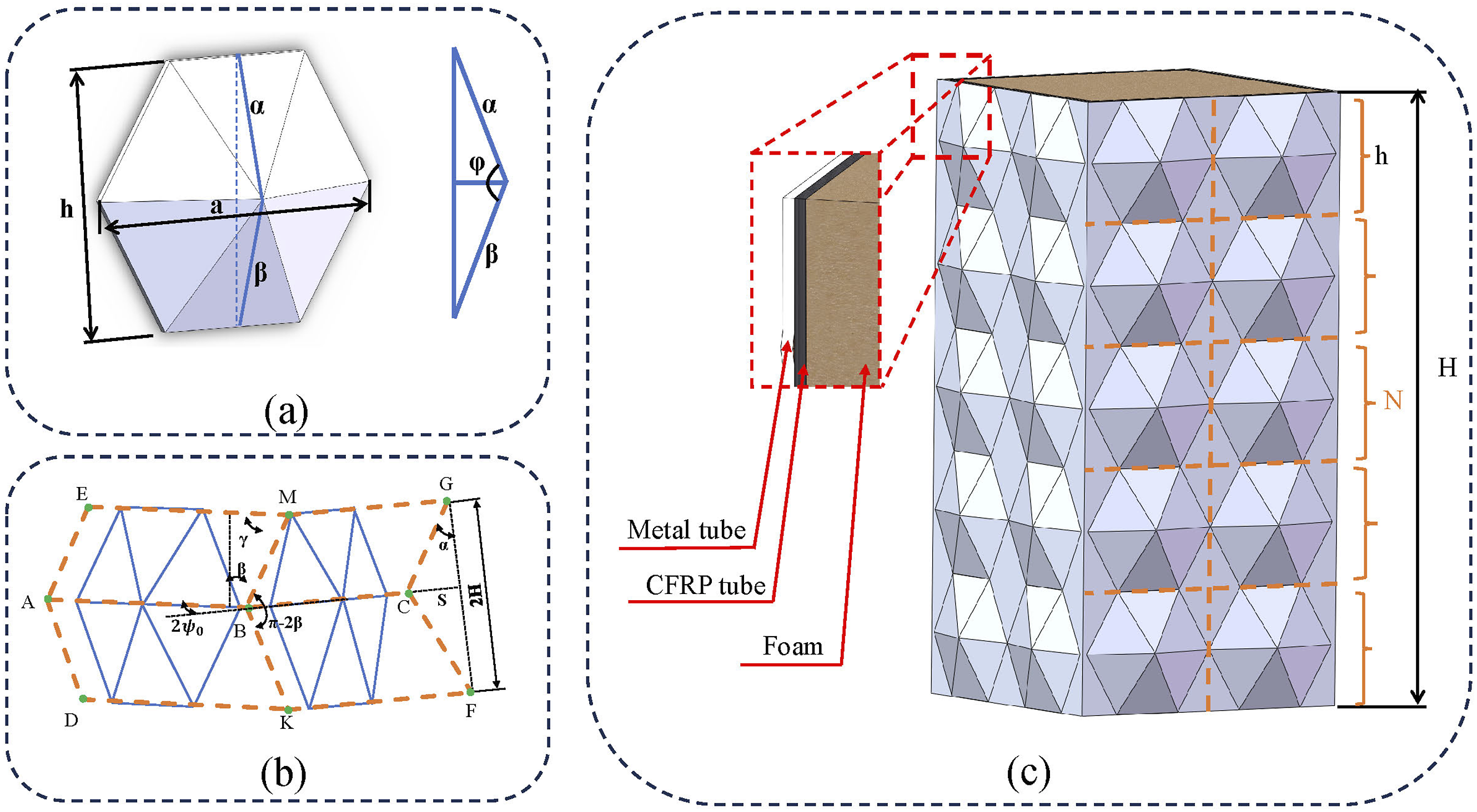
In this study, the metal thin-walled tube is made of 316L material using 3D printing. Based on the designed dimensions of the metal square tube, a pre-folded hexagonal pattern is introduced on the outer wall of the metal square tube. The folds guide the deformation mode of the thin-walled tube during axial crushing, reducing the initial peak force of the thin-walled tube and making the deformation of the structure more stable and controllable. These patterns are generated by arranging identical basic pattern units, as shown in Figure 1(a). The cross-sectional shape of the basic pattern unit is hexagonal, and the overall shape is a hexagonal pyramid. The overall width of the basic pattern unit, a = 20.1 mm, is kept constant. The angle between the upper and lower α and β planes in the longitudinal direction is the dihedral angle φ. This study investigates the impact of φ values of 140°, 150°, and 160° on energy absorption. In Figure 1(c), the arrangement of the basic patterns on the metal tube is shown. The height (h) of the basic pattern unit is adjusted to alter the number of pattern layers Metal 3D printing process.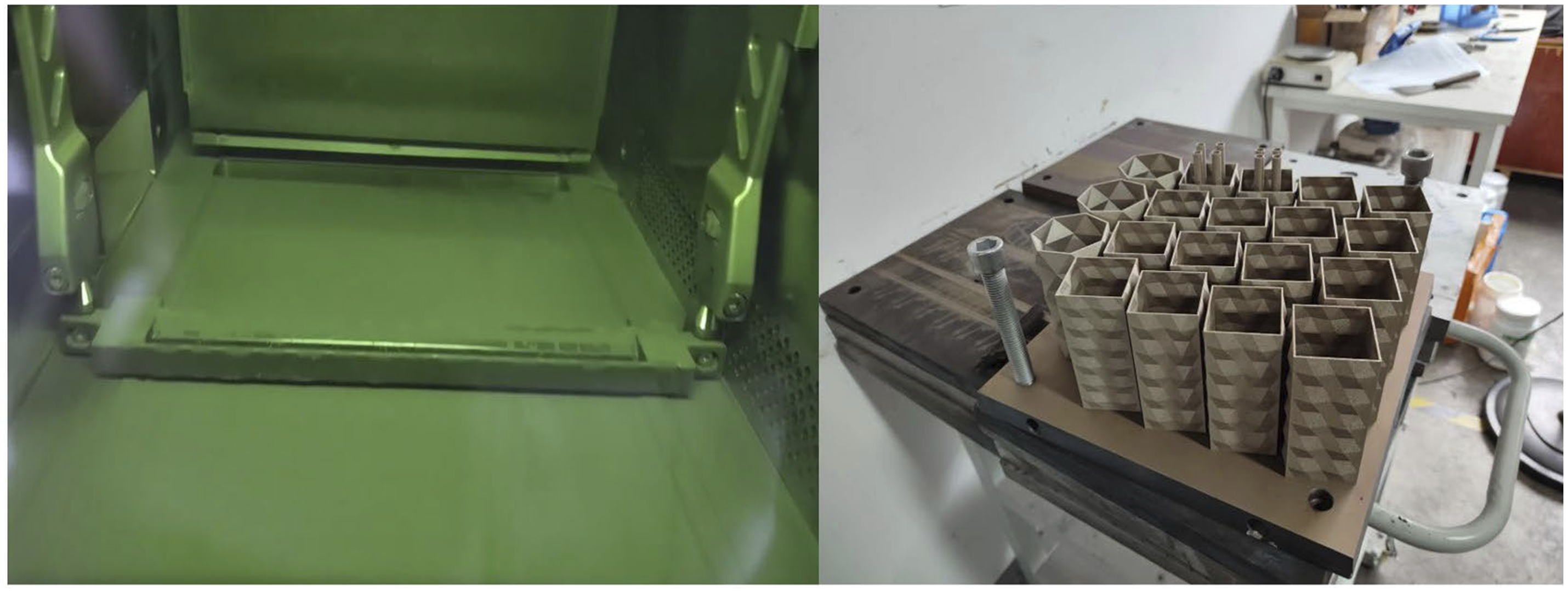
The CFRP tube is made using T700 material, with the carbon fiber square tube having an inner edge length of 40 × 40 mm and consisting of 6 layers of carbon fiber. Due to process errors during the manufacturing of the specimen, to ensure proper assembly of the inner CFRP tube and the outer metal tube, the manufacturing errors should be minimized. Ultimately, the CFRP square tube and the outer metal tube are assembled in an interference fit form. As shown in Figure 3(a), the manufacturing process of the CFRP tube in this study begins by impregnating carbon fiber bundles with epoxy resin, then winding them onto a rectangular mold with an edge length of 40 mm. The tube is sealed in a vacuum bag and placed in a constant temperature heating chamber to cure. After demolding and simple polishing, the final product is obtained. Figure 3(b) shows the schematic design of the fiber lay-up angle for the CFRP tube. The fiber winding angle is denoted as θi (i = 1,2), and the 6-layer lay-up angle is represented as [θ1°/−θ2°/90°/90°/θ2°/−θ1°], using a symmetric reverse lay-up design. This is later represented as [θ1°/−θ2°/90°]2. The axial direction of the thin-walled tube is defined as the 0° angle, and the circumferential direction is the 90° angle. In this study, the values of θ can be chosen as 10°/30°/50°/70°/90°, etc. Fabrication of CFRP tubes; (a) Fabrication process of CFRP tubes; (b) fiber angle of CFRP tubes.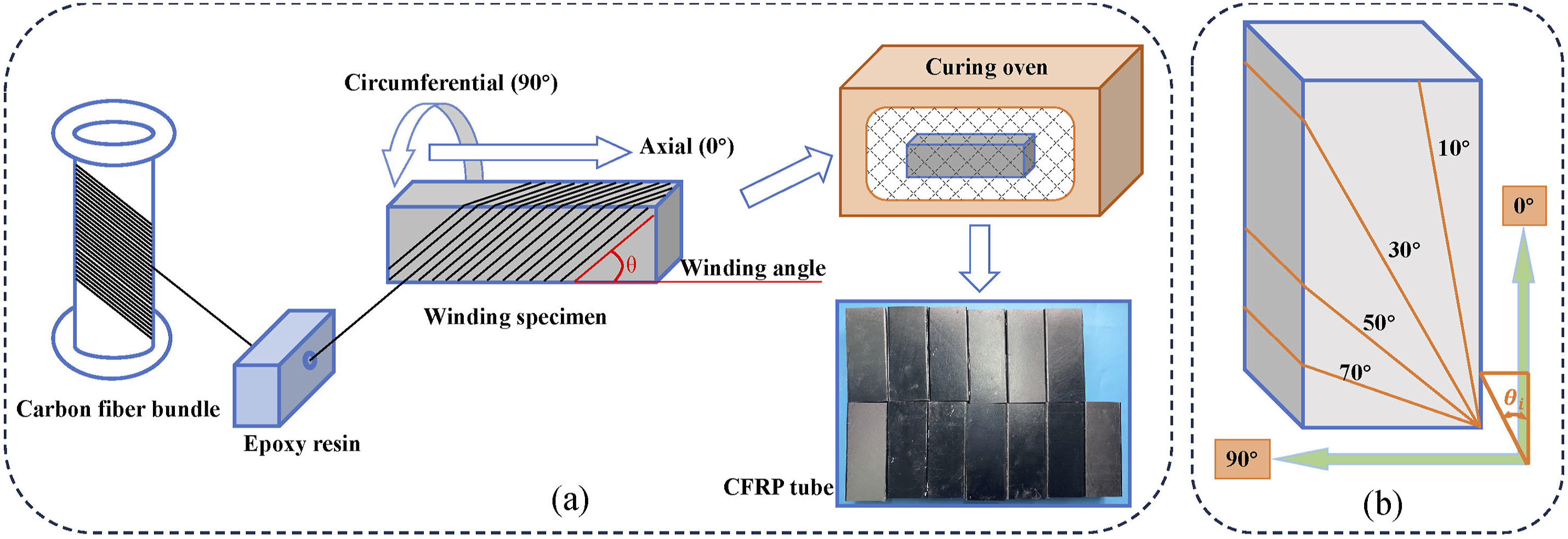
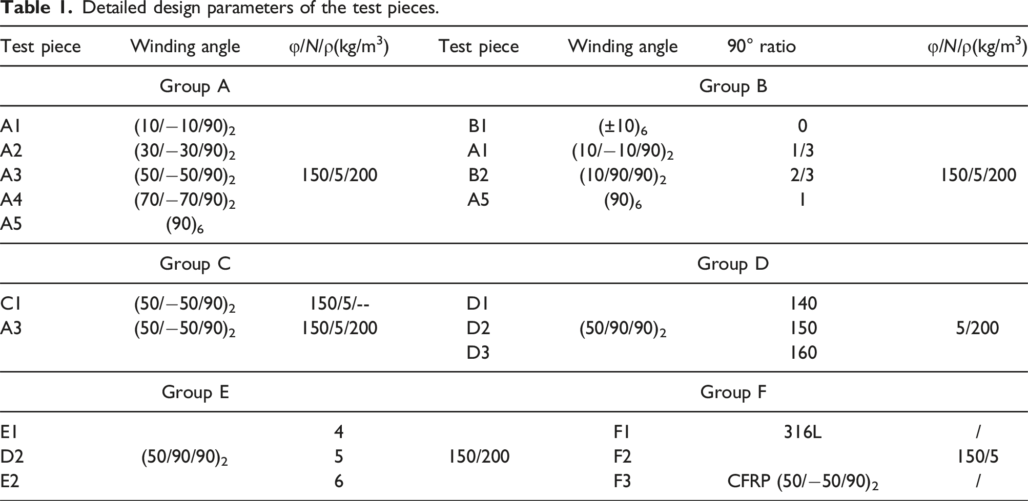
Detailed design parameters of the test pieces.
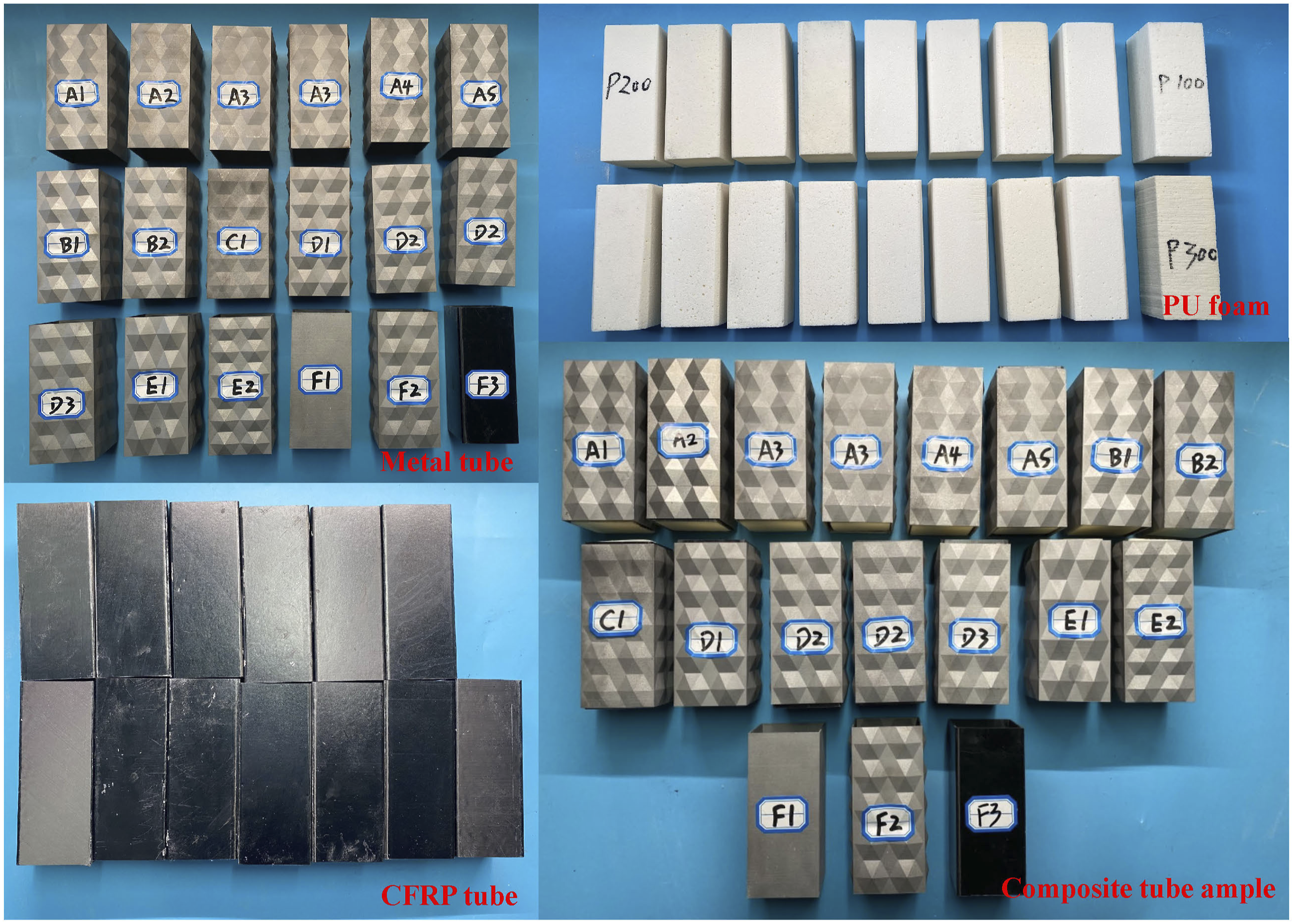
Display of test pieces.
Measurement of energy absorption properties
In this study, a 200 KN universal testing machine was employed to conduct quasi-static compression tests on the composite thin-walled tubes. During the experiment, the sample was positioned at the center of the baseplate of the testing machine, while the indenter applied a displacement load at a rate of 8 mm/min. The total displacement applied by the indenter was 60 mm. The testing apparatus continuously recorded the load-displacement data throughout the experiment. The setup of the universal testing machine is shown in Figure 5. Quasi-static compression test device.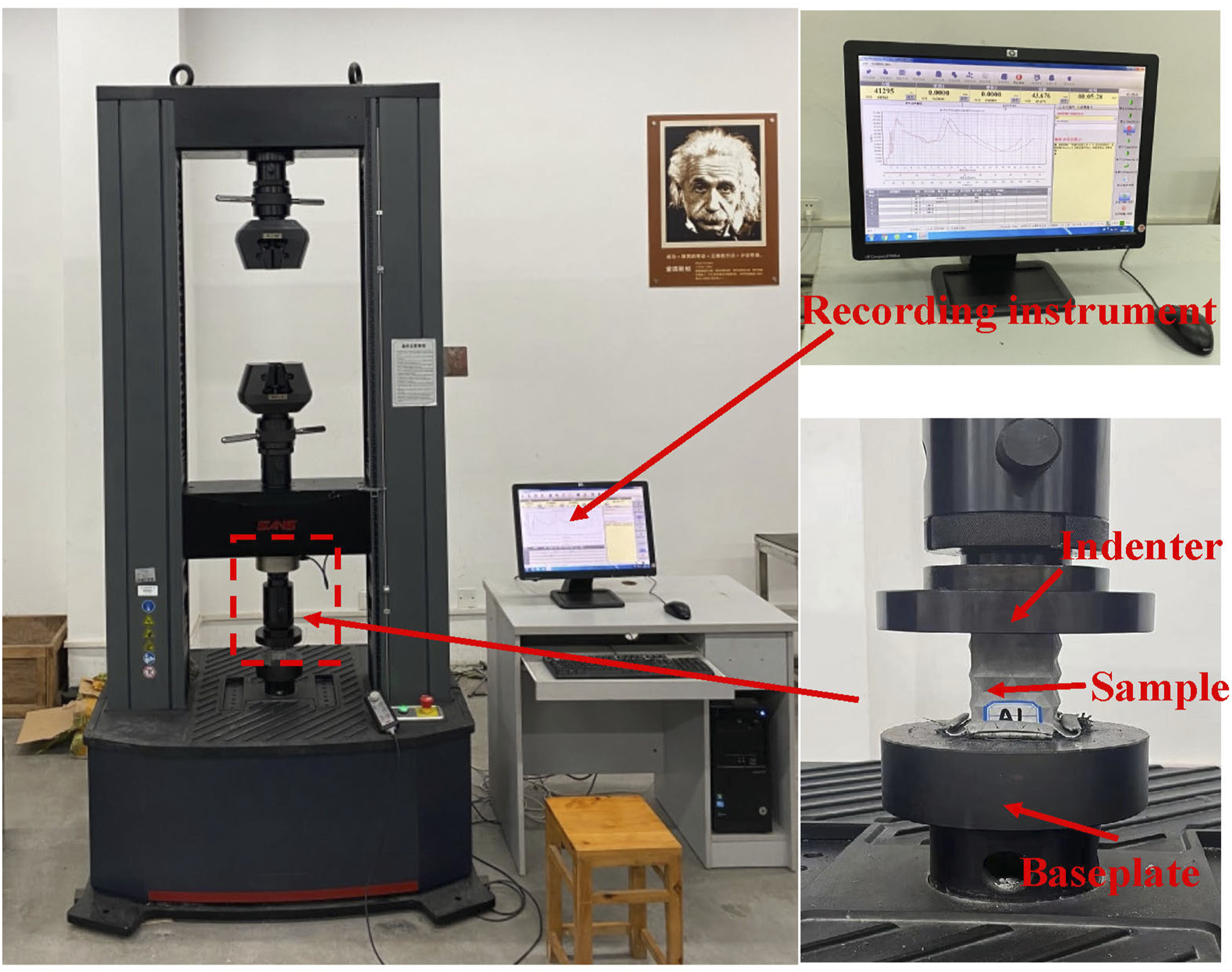
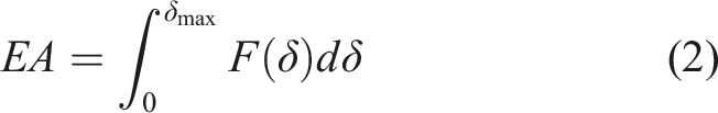
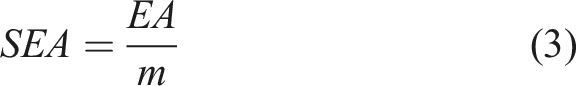
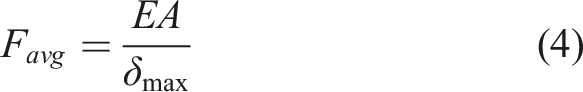
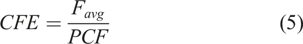
To accurately evaluate the energy absorption properties of the composite tube under axial crushing, several key indicators were employed for quantitative analysis of the axial energy absorption performance, including the peak crushing force (PCF), total energy absorption (EA), specific energy absorption (SEA), average crushing force (Favg), and crushing force efficiency (CFE).
41
These parameters are defined as follows: 1. Peak Crushing Force (PCF) refers to the maximum force encountered during the initial phase of the crushing process. It corresponds to the critical state where the structure first undergoes deformation. Excessively high PCF can result in elevated crash acceleration, posing a significant safety risk to vehicle occupants. 2. Total Energy Absorption (EA) represents the total energy absorbed by the structure throughout the entire crushing process, primarily achieved through the progressive failure of the energy-absorbing structure. It serves as a key indicator in assessing the structure’s ability to dissipate external impact energy. The expression for total energy absorption is given by: where F(δ) is the crushing force as a function of the displacement δ , and δmax is the maximum crushing displacement. 3. Specific Energy Absorption (SEA) refers to the amount of energy absorbed per unit mass of the energy-absorbing component during the crushing process. It is used to evaluate the efficiency of the material in absorbing energy. The expression for SEA is given by: where m represents the total mass of the energy-absorbing component. 4. Average Crushing Force (Favg): This parameter represents the average load experienced by the energy-absorbing component during the entire crushing process. It can be expressed as: 5. Crushing Force Efficiency (CFE) is the ratio of the average crushing force (Favg) to the initial peak crushing force (PCF). It reflects the load uniformity of the structure. A higher CFE indicates lower load fluctuations in the energy-absorbing component, a smoother load-displacement curve, and more stable deformation of the structure. The expression for CFE is:

Numerical simulation
Composite material failure criteria
Unlike metal materials, composites exhibit complex failure modes during damage progression, including matrix tensile failure, matrix compressive failure, and fiber tensile failure. Unidirectional fiber-、upeinforced composites belong to orthotropic materials, and to better account for out-of-plane displacement, a three-dimensional constitutive model was employed in this study.
5
The stress-strain relationship is described as follows: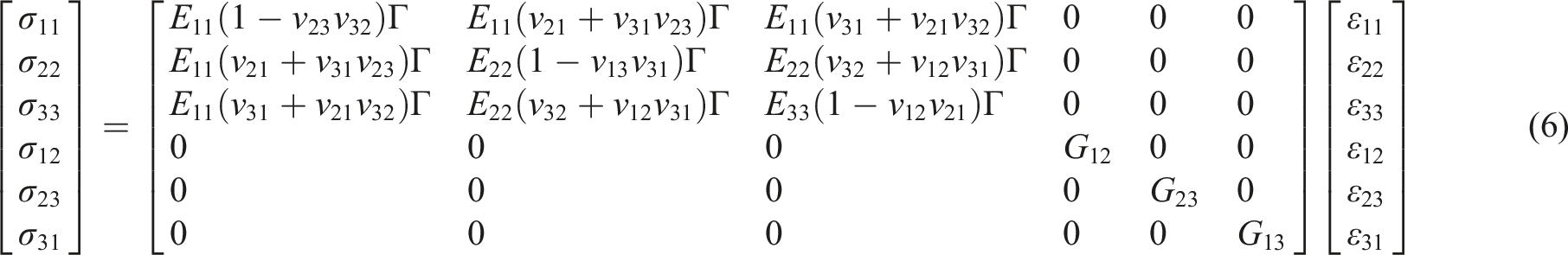
In this model, 
To more accurately simulate the failure behavior of composite layers and elucidate the material failure mechanisms, this study employs the three-dimensional Hashin damage initiation criteria. The model incorporates both in-plane and out-of-plane shear failure modes. The Hashin damage initiation criteria are strain-based and account for six types of failure modes: fiber tensile, fiber compressive, matrix tensile, matrix compressive, in-plane shear, and out-of-plane shear. The expressions for these failure modes are as follows
42
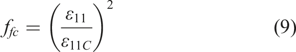
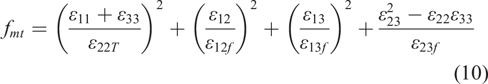
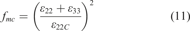
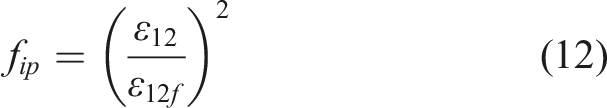
: 1. Fiber tensile failure: 2. Fiber compressive failure: 3. Matrix tensile failure: 4. Matrix compressive failure: 5. In-plane shear failure: 5. Out-of-plane shear failure:
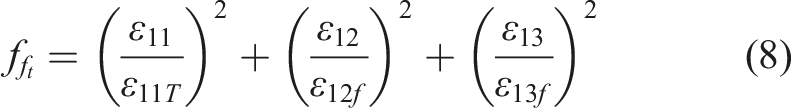
In the equations (1)–(3) correspond to the fiber direction (X), the in-plane direction perpendicular to the fiber direction (Y), and the out-of-plane direction perpendicular to the fiber direction (Z), respectively, as illustrated in Figure 6. Composite fiber microstructure. Material parameters for CFRP composites.
43
In Table 2, E11, E22, and E33 denote the elastic moduli in the 1, 2, and 3 directions, respectively. G12, G13, and G23 represent the shear moduli in the 1-2, 1-3, and 2-3 planes, respectively.
In the simulation of composite material failure, interlaminar failure must also be accounted for. This study employs cohesive contact to analyze interlaminar failure, with the traction-separation law defining the material model’s contact behavior. Figure 7 depicts the bilinear traction-separation law.
44
Prior to failure, the relationship between cohesive stress and displacement is characterized by a linear elastic constitutive model. Upon meeting the initial damage criterion (point A), damage initiation at the interface leads to stiffness degradation, culminating in delamination failure at point B. In this model, t represents the cohesive stress vector, while tn, ts, and tt denote the normal stress, shear stress in the first direction, and shear stress in the second direction, respectively. The stiffness matrix is denoted by K, and δ represents the displacement vector, with δn, δs, and δs indicating the normal displacement, shear displacement in the first direction, and shear displacement in the second direction, respectively.
45
Bilinear traction-separation law.
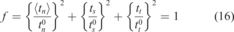
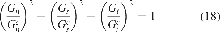
In the elastic deformation range, interlaminar failure can be defined as: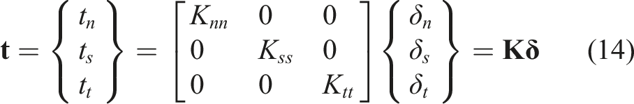
Upon reaching the elastic limit, interlaminar failure progresses to a nonlinear evolution stage, defined as: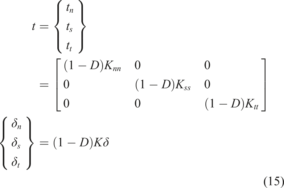
In the equations, 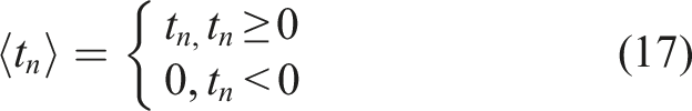
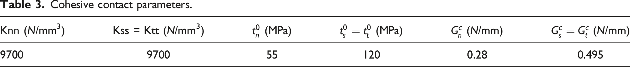
Cohesive contact parameters.
Finite element modeling
The composite tubes’ crushing behavior under axial loads was numerically simulated using the commercial finite element software ABAQUS/Explicit. The model comprised an upper loading rigid plate, a bottom fixed rigid plate, a CFRP tube, a metal tube with origami pattern, and a foam filling block, as illustrated in Figure 8. In the simulation of the axial crushing process, constraints were applied to the reference point of the bottom fixed rigid plate, restricting all six degrees of freedom. To ensure that the upper loading rigid plate moved consistently along the tube’s axial direction, constraints were also imposed on the reference point of the upper loading rigid plate, restricting all but three degrees of freedom. A displacement of 60 mm along the negative Z-axis was set, accompanied by a smooth loading amplitude curve based on the analysis step. Setup of finite element modeling.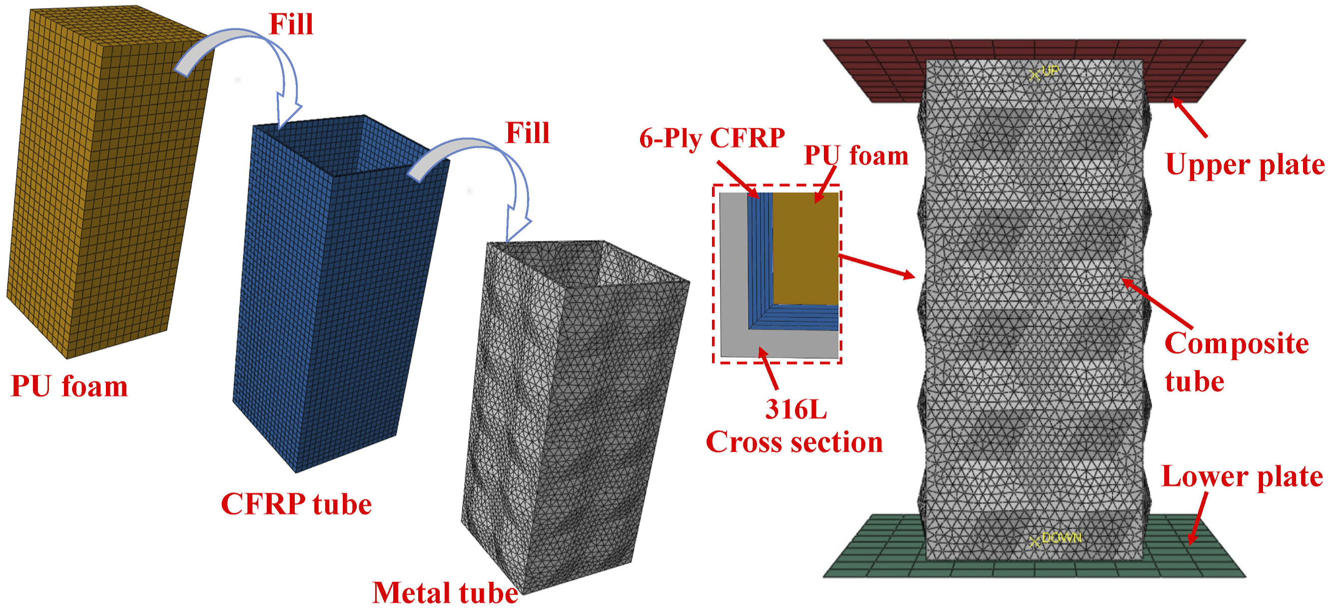
To ensure computational accuracy and efficiency, a comparison of the mesh sizes for the metal tube with origami pattern (specimen F2) and the CFRP tube (specimen F3) was conducted. The metal tube with origami pattern was analyzed using three mesh sizes: 1 mm, 2 mm, and 3 mm. For the CFRP tube, three mesh sizes were used: 1 mm, 1.5 mm, and 2 mm. The results for each mesh size were compared to select the most suitable mesh size. Figure 9 illustrates the load-displacement results for the metal tube with origami pattern and the CFRP tube using the three different mesh sizes. The comparison of different mesh sizes revealed that for the metal tube with origami pattern, the load-displacement curves were similar for mesh sizes of 1 mm and 2 mm, with both showing good agreement with the experimental load-displacement curve. In contrast, a 3 mm mesh size resulted in significantly different simulation results compared to the 1 mm and 2 mm meshes. For the CFRP tube, the load-displacement curves were well matched for mesh sizes of 1 mm and 1.5 mm, whereas a 2 mm mesh size showed considerable deviation from the curves obtained with 1 mm and 1.5 mm meshes, as well as from the experimental data, notably exhibiting a higher overall load. Therefore, considering both computational accuracy and efficiency, a mesh size of 2 mm was selected for the metal tube with origami pattern, while a mesh size of 1.5 mm was chosen for the CFRP tube. Comparison of models with different mesh sizes.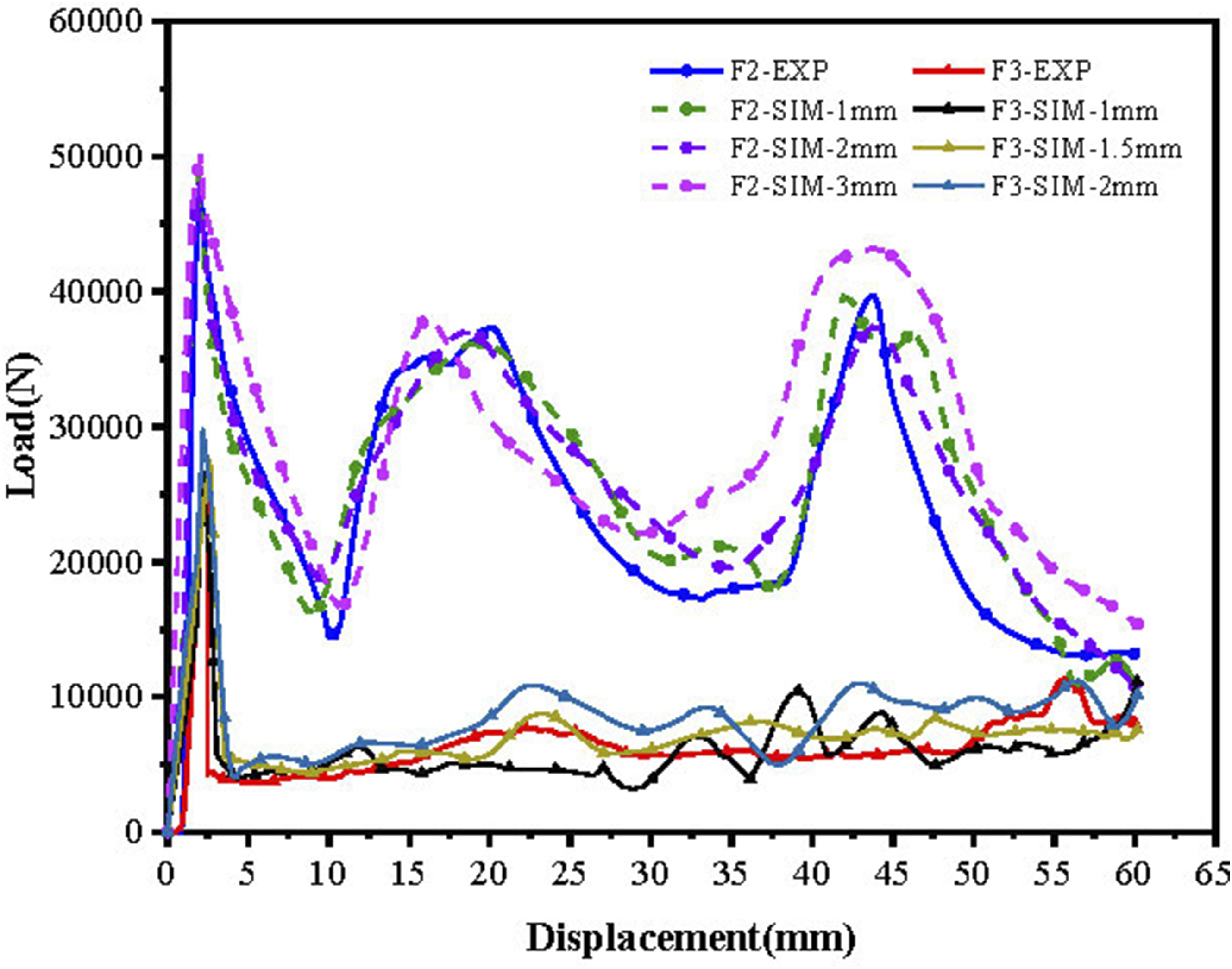
Johnson-Cook constitutive model parameters for 316 L steel. 46
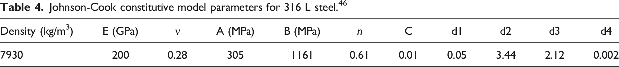
E represents the Young’s modulus, ν is the Poisson’s ratio, A is the initial yield stress at the reference strain rate and temperature, B denotes the material’s strain hardening modulus, n is the strain hardening exponent, C is the material’s strain rate sensitivity parameter, and di (i = 1,2,3,4) are the damage parameters.
The CFRP square tubes were modeled using solid elements configured as deformable bodies. The cross-sectional attributes were defined as homogeneous solids, and the three-dimensional Hashin failure criterion, based on strain, was applied through the VUMAT subroutine. The meshing of the CFRP square tubes was conducted using hexahedral swept elements, with a grid size of 1.5 mm, resulting in a total of 43,416 C3D8R elements. The sweeping direction was aligned with the fiber ply direction, extending from the inner to the outer surface of the tube. Elements were designated for deletion to accurately represent the material behavior. To simulate the delamination damage of CFRP, cohesive contact between adjacent layers was defined based on the “general contact algorithm,” including friction coefficients, viscosity parameters, and interlaminar damage. To prevent interpenetration between elements and ensure the accuracy of the simulation results, a “hard contact algorithm” was implemented. The internal polyurethane foam was modeled using solid elements as a deformable body.
Numerical simulation results validation
To validate the accuracy of the numerical simulation, the simulation results were compared with the quasi-static compression test results of the samples, as shown in Figure 9. The overall trend of the load-displacement curve obtained from the finite element simulation of both the metal tube with origami patterns and the CFRP tube aligns well with the quasi-static compression test results of the samples. Figure 10(a) presents the comparison between the numerical simulation and the experimental load-displacement curves for composite tube D3. Similar to the hollow tube results, the overall trend of the finite element simulation load-displacement curve closely matches the quasi-static compression test results of the samples. Comparison of numerical simulation and experimental results; (a) comparison of D3 load-displacement curves; (b) comparison of deformation processes for F2; (c) comparison of deformation processes for D3; (d) comparison of deformation processes for F3.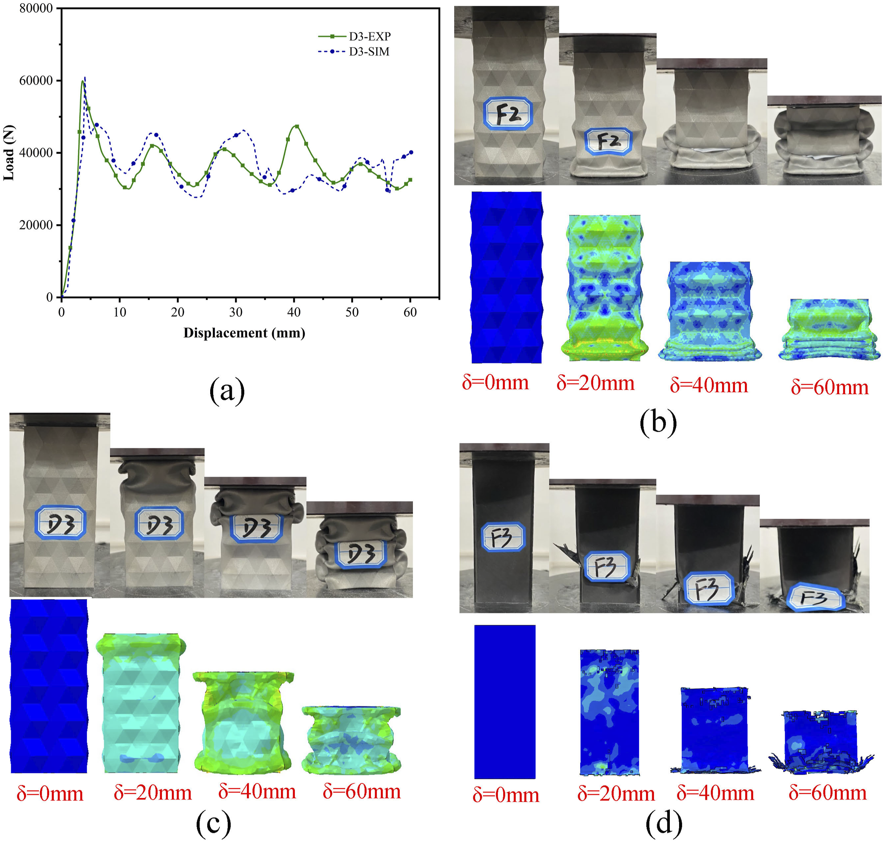
Comparison of energy absorption properties between numerical simulations and experimental results.
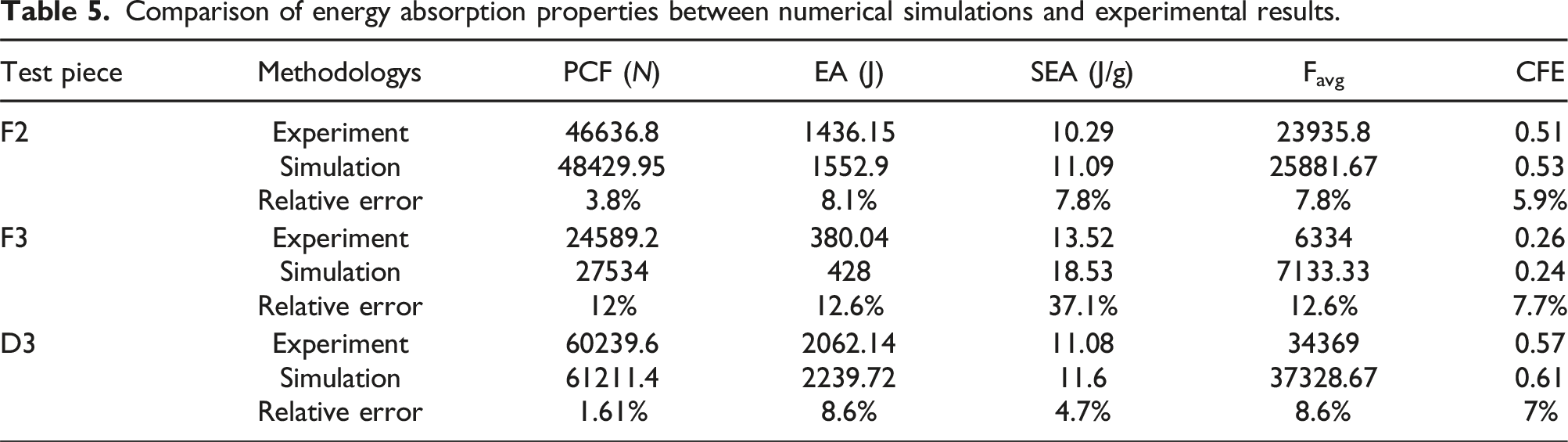
Figure 10(b) and (c) illustrate the comparison of deformation processes between numerical simulations and experiments for the metal tube with origami patterns and the composite tube. At equivalent displacements, the deformation states observed in the numerical simulations exhibit a high degree of consistency with those recorded in the experiments. Both types of tubes demonstrate stacking along pre-folds, resulting in a progressive folding deformation mode. Figure 10(d) compares the deformation processes of the CFRP tube in the numerical simulation and experiment. In the simulation, where unit deletion was applied, the observed failure mode closely mirrors the experimental findings: the lower portion of the tube initially experiences fractures, followed by progressive fiber breakage and circumferential matrix cracking which indicates a fragmentation failure mode. The integration of the load-displacement curves and axial crushing deformation processes from both numerical simulations and experimental results supports the conclusion that the finite element numerical simulation method employed in this study is reliable for simulating the axial quasi-static compression tests of metal tubes and CFRP composite tubes with origami patterns.
Study on design parameters of composite tubes
The study primarily relies on experimental validation and supplements it with numerical simulations to analyze the energy absorption mechanisms of composite thin-walled tubes. The research investigates the impact of various design parameters on the performance characteristics of composite tubes. These parameters include the structure of the hollow tube, foam filling, carbon fiber winding angle, fiber winding ratio, and the angle and number of layers in metal tubes with origami patterns. The samples were categorized into six groups, and a controlled variable method was employed to examine the influence of each factor on energy absorption properties.
Analysis of energy absorption mechanisms in composite thin-walled tubes
The composite tubes studied in this research exhibit multiple modes of energy absorption under quasi-static compression, encompassing the deformation of metal, composite materials, and polyurethane foam, as well as the interactions between these components. Figure 11 illustrates the axial crushing of single metal tubes (F1, F2). The images show that the metal tubes exhibit a stacked configuration. During compression, the metal tubes undergo a progressive collapse process. The primary mechanism for energy dissipation is through the plastic deformation of the metal, which occurs in regions where plastic hinges are formed during the compression process of the metal tubes.
47
From the figure, it can be observed that the single metal tube F1 primarily undergoes non-compact mode deformation, resulting in discontinuous deformation wrinkles separated by slightly bent square plates. In other words, the upper and lower wrinkles formed do not contact each other. The square tube only undergoes local folding, which is insufficient deformation, and the overall structure is more unstable, prone to Euler buckling, which should be avoided during energy absorption in the deformation of the square tube. On the other hand, the single origami-pattern metal tube F2 experiences complete plastic deformation in a compact mode. The wrinkles formed on the square tube stack, making contact and remaining continuous, and the tube wall forms wave-like folds in the compression direction. This results in a higher material utilization rate for the square tube. The reason for this phenomenon is mainly due to the pre-formed folds in the origami-pattern metal tube. These folds guide the deformation, making the metal tube’s deformation more complete and stable. Axial crushing failure modes of single metal tubes.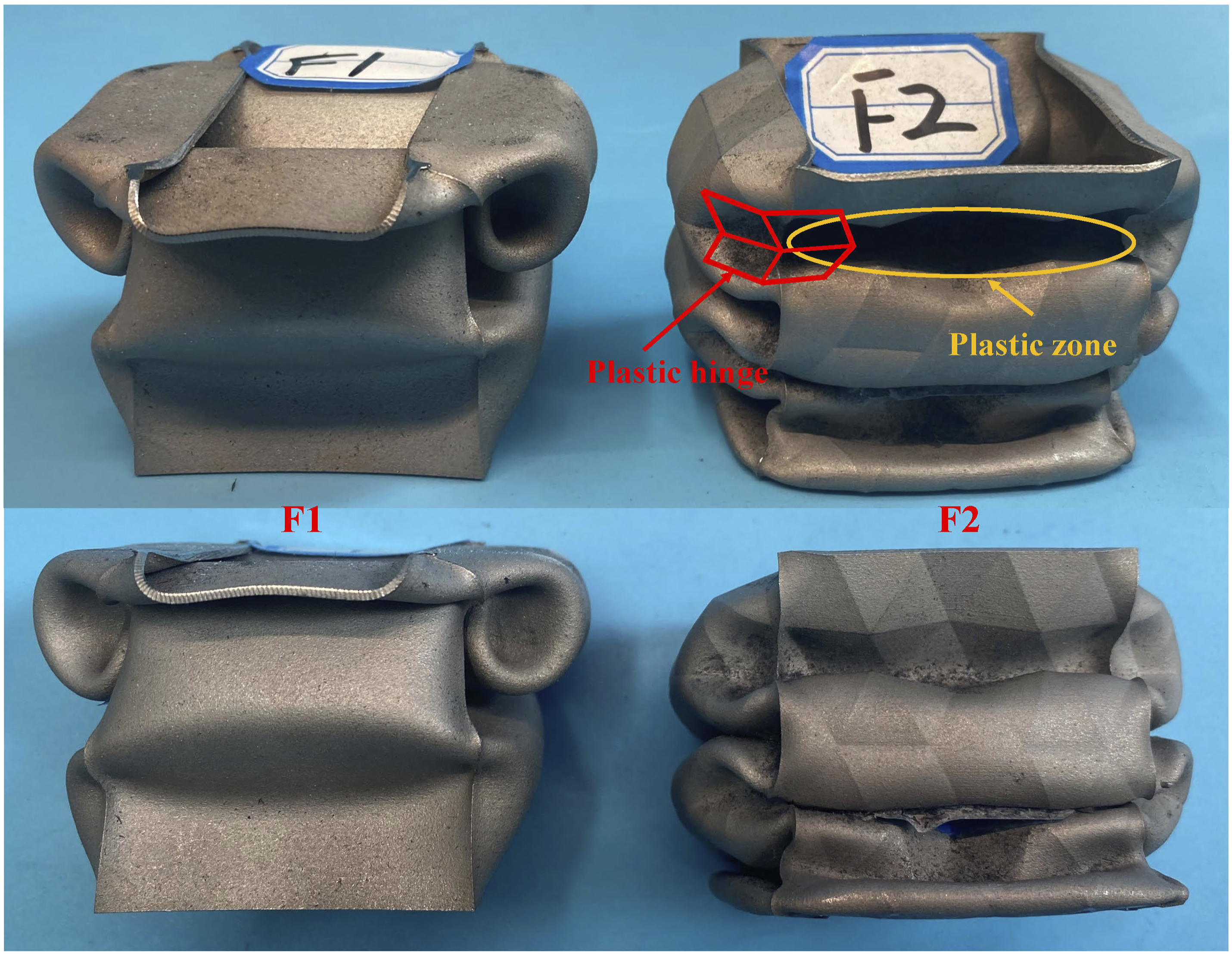
The failure modes of composite materials are intricate, encompassing multiple mechanisms such as fiber failure, matrix failure, and delamination.
8
Figure 12(a) illustrates the crushing results of the composite tube A1 sample. The CFRP tube exhibits failure modes characterized by both layer-wise and bundle-wise bending. These failures are primarily influenced by the fiber winding angle. In the CFRP square tube, tearing occurs at the four corners, with the fractured layers bending outward, resulting in layer-wise and bundle-wise bending failures. This failure is accompanied by interlaminar delamination, fiber breakage, and matrix fracture, ultimately leading to the fragmentation of the material. Figure 12(b) presents the crushing results of the composite tube A4 sample, in which the CFRP tube exhibits transverse shear failure modes, followed by bundle-wise failure. These failure modes are primarily caused by the combined effects of fiber breakage and matrix fracture. Numerous cracks can be observed at the crushing site, and as compression progresses, the damage gradually propagates downward. Due to the influence of the progressive folding deformation of the external metal tube with origami patterns, the layer-bundle fractures resulting from the shear failure in the CFRP tube also tend to exhibit a gradually stacked morphology. Axial crushing failure modes of composite tubes; (a) crushing result of A1 sample; (b) crushing result of A4 sample.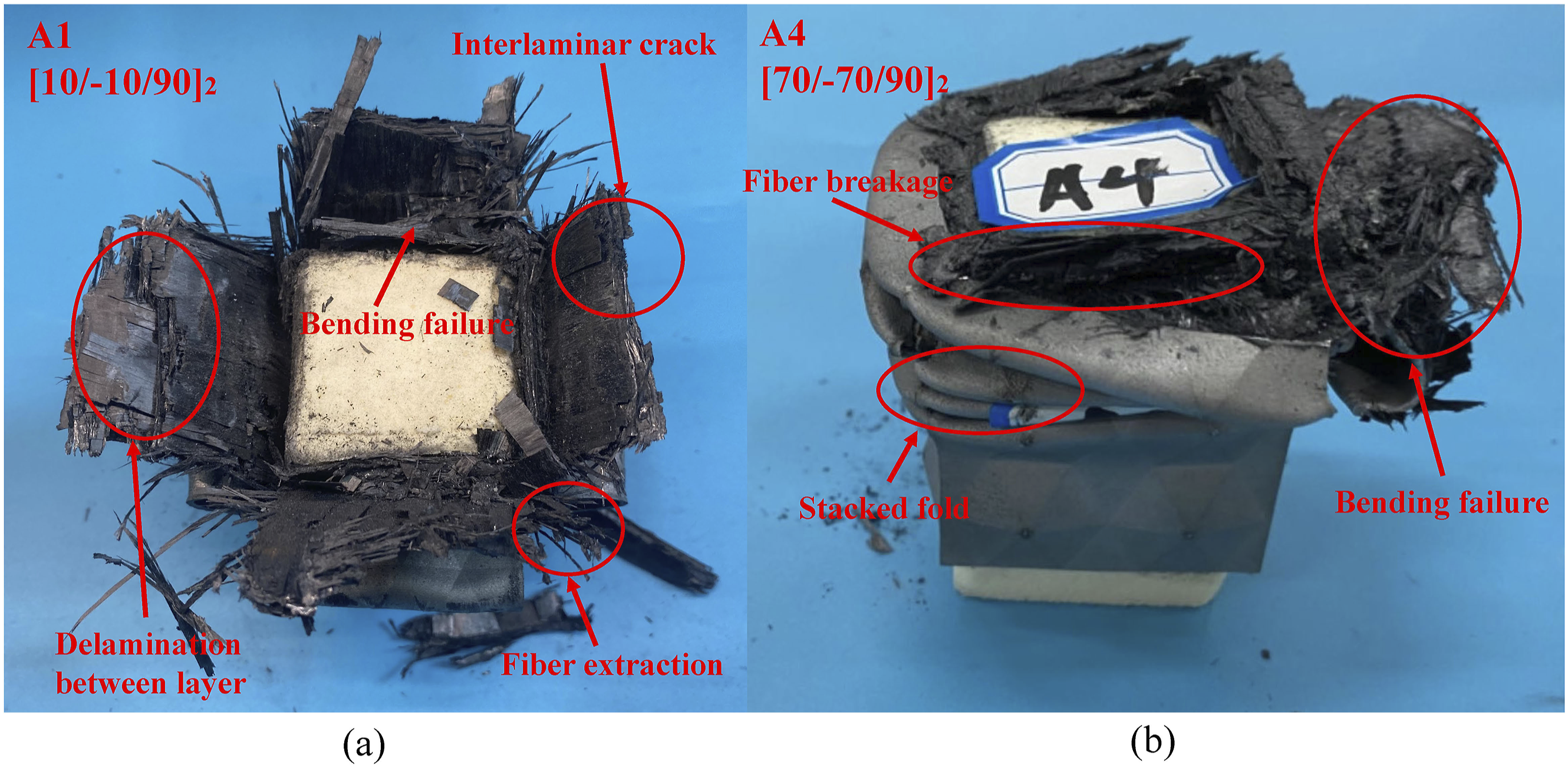
The internal foam filling within thin-walled tubes serves as a constraint, impeding inward bending and thereby altering the crushing mode, which enhances energy absorption performance. In Figure 13, the axial crushing deformation process and load-displacement curves are presented for foams with densities of 100 kg/m3, 200 kg/m3, and 300 kg/m3. It is evident that the 100 kg/m3 foam remained intact during compression but exhibited a lower degree of densification. The 300 kg/m3 foam, however, fractured during compression and demonstrated a higher initial peak load. In contrast, the 200 kg/m3 polyurethane foam exhibited optimal compressive performance, with higher densification and no fragmentation, maintaining overall structural integrity. Consequently, for the analysis of the influence of foam filling on the energy absorption properties of composite tubes, 200 kg/m3 polyurethane foam was employed in this study. Axial crushing deformation process and load-displacement curves of foams with varying densities.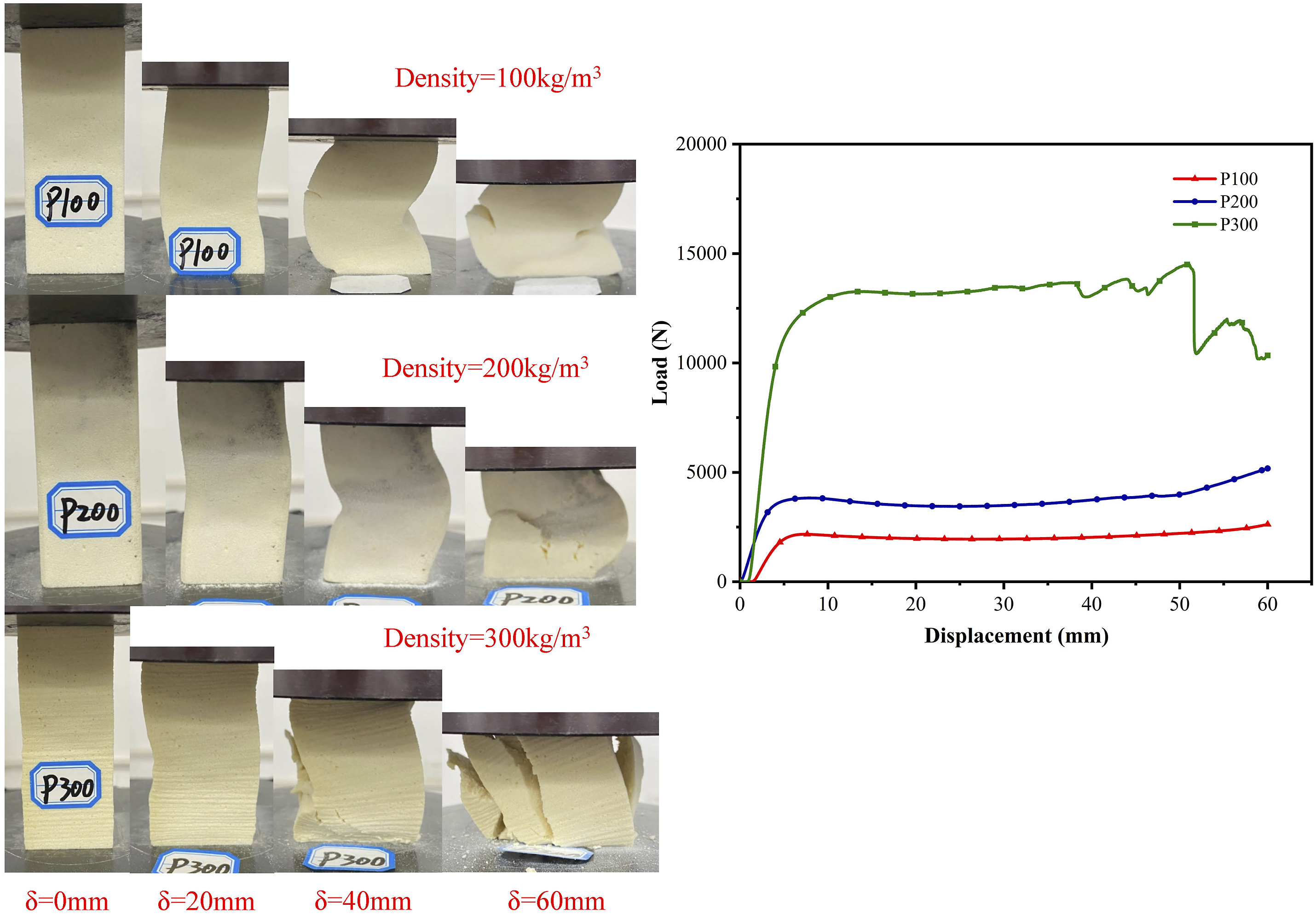
Comparison of energy absorption in hollow tubes
The energy absorption properties of thin-walled tubes vary significantly depending on the material and structural design. Metallic materials primarily absorb energy through plastic deformation, while composite materials dissipate energy through interlaminar delamination, fiber breakage, and other failure mechanisms. To investigate these differences, this study considers three distinct thin-walled tube samples: the straight metal tube (F1 sample), the metal tube with origami patterns (F2 sample), and the hollow carbon fiber tube (F3 sample with ply orientations of 50/-50/90)2. Their respective energy absorption properties were evaluated.
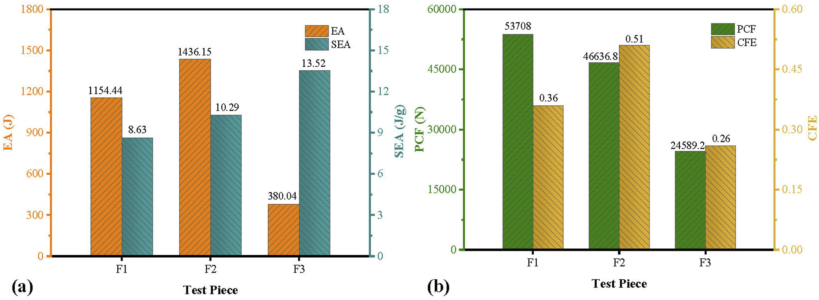
In Figure 14, the load-displacement curves for the hollow tubes are presented. It is evident that all three samples experience a significant reduction in crushing load after reaching the peak value. The crushing load of the F1 sample stabilizes after the initial drop, but the overall load level remains relatively low, indicating poor energy absorption efficiency. For the F3 sample, the initial load peak sharply decreases. This abrupt decline is attributed to the catastrophic brittle fracture of both the matrix and fibers in the central section of the CFRP tube during crushing, which has a detrimental effect on the energy absorption properties of composite tubes. Additionally, the occurrence of fractures influences the subsequent deformation and load-bearing capacity of the CFRP tube, as seen by the continuously low load level following the sharp drop, ultimately resulting in poor energy absorption performance. In contrast, the F2 sample exhibits a rapid increase in load after the initial drop, forming a load-displacement curve with two distinct peak fluctuations. These peak fluctuations correspond to the formation of two folds during the crushing process, as observed in Figure 10 for the F2 sample. Figure 15 presents the energy absorption properties data of hollow tubes under crushing. It can be observed that, despite the initial peak load of the mental tube with origami patterns F2 being 13.17% lower than that of the single metal straight tube F1, the total energy absorption of F2 increased by 24.4%, and the specific energy absorption (SEA) improved by 19.24%. Furthermore, F2 demonstrated higher crash force efficiency (CFE) compared to F1, clearly indicating that the introduction of origami patterns in metal thin-walled tubes significantly enhances the overall energy absorption properties. On the other hand, the total energy absorption of the single carbon fiber hollow tube (F3 sample) was the lowest among the three samples, primarily due to mid-section failure. This also led to lower CFE. However, owing to its lighter weight, the SEA of F3 was the highest among the three samples, highlighting the enormous potential of CFRP tubes in energy absorption applications. This finding reinforces the innovative approach of combining metal and composite materials in this study to enhance the energy absorption properties of thin-walled tubes. Load-displacement curves of hollow tubes. Energy absorption properties data of hollow tubes under crushing; (a) SE and SEA data for Group F samples; (b) PCF and CFE data for Group F samples.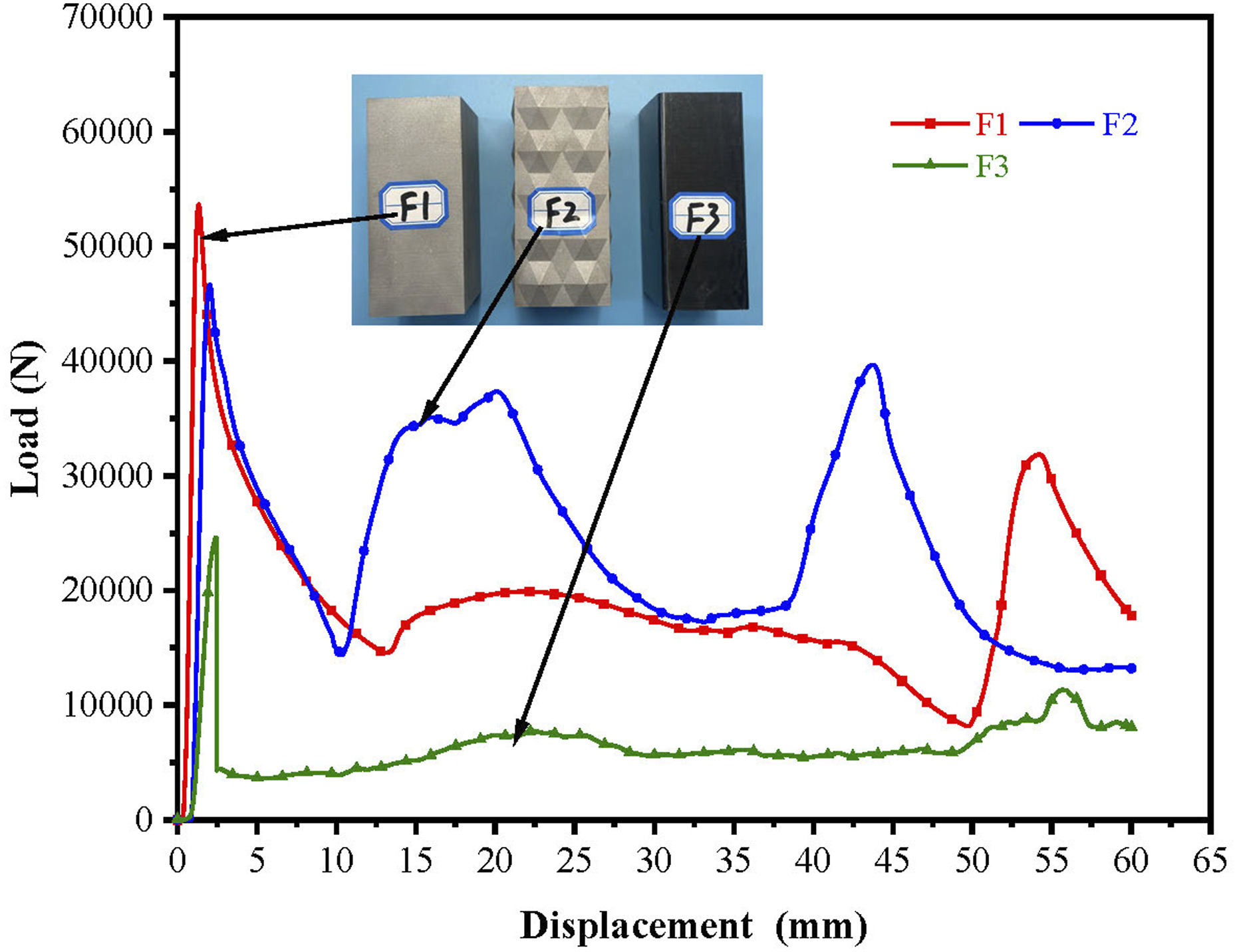
The impact of foam filling
To investigate the effect of internal polyurethane foam filling on the energy absorption properties of composite tubes, a comparison was made between the origami pattern metal/CFRP composite tube C1 sample (without foam filling) and the composite tube with identical design parameters but with internal foam filling, A3 sample. Figure 16(a) illustrates the axial compression deformation processes of both samples. It is observed that in the C1 sample, the CFRP tube primarily undergoes transverse shear failure, accompanied by interlaminar delamination and fiber breakage. Due to the interaction between the metal and carbon fiber composite tubes, tearing occurs at the four corners of the metal tube. During compression, the metal tube’s four faces roll outward, causing significant load drop. However, by comparing the load-displacement curves of C1 sample in Figure 16(b) and F3 sample in Figure 14, it is evident that the combination of the metal tube and CFRP tube significantly improves the energy absorption properties of the thin-walled tubes, which enhances the overall crushing load capacity and stabilizes load fluctuations. In the A3 sample, the CFRP tube primarily exhibits transverse shear failure as well as layered and bundle-type bending failure. Corresponding to the bending failure of the CFRP tube, the metal tube exhibits corner tearing and outward curling deformation on two of its faces, while the other two faces display wrinkling and stacking. As illustrated by the load-displacement curve for A3, the curve consistently remains above that of C1, indicating superior overall energy absorption and deformation stability. It is noteworthy that both curves show a significant load drop upon reaching the initial peak, with similar magnitudes of decline, which can be attributed to the tearing of the metal tube’s corners during the initial compression phase. However, due to the foam filling in the A3 sample, the subsequent deformation mode of the tube differs from that of C1, resulting in better final energy absorption performance for the A3 sample. Impact of foam filling; (a) axial compression deformation process of C1 and A3; (b) load-displacement curves of C1 and A3 during axial compression.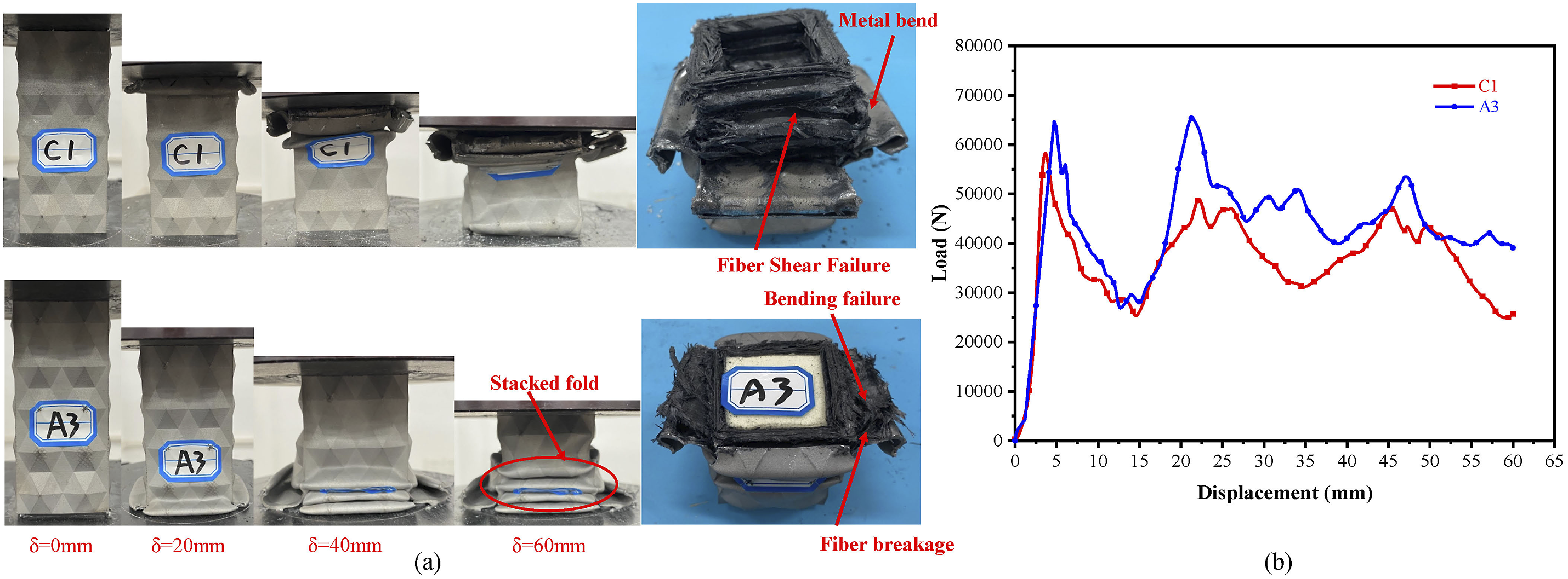
Figure 17 presents the energy absorption properties data with foam filling. It can be observed that, following the introduction of foam filling, the initial peak load of the tube increased by 10.18%, and the total energy absorption improved by 16.81%. Furthermore, both specific energy absorption and impact force efficiency exhibited notable enhancements. These findings demonstrate that foam filling positively influences the energy absorption properties of composite tubes. Energy absorption properties data with foam-filling; (a) EA and SEA data for samples C1 and A3; (b) PCF and CFE data for samples C1 and A3.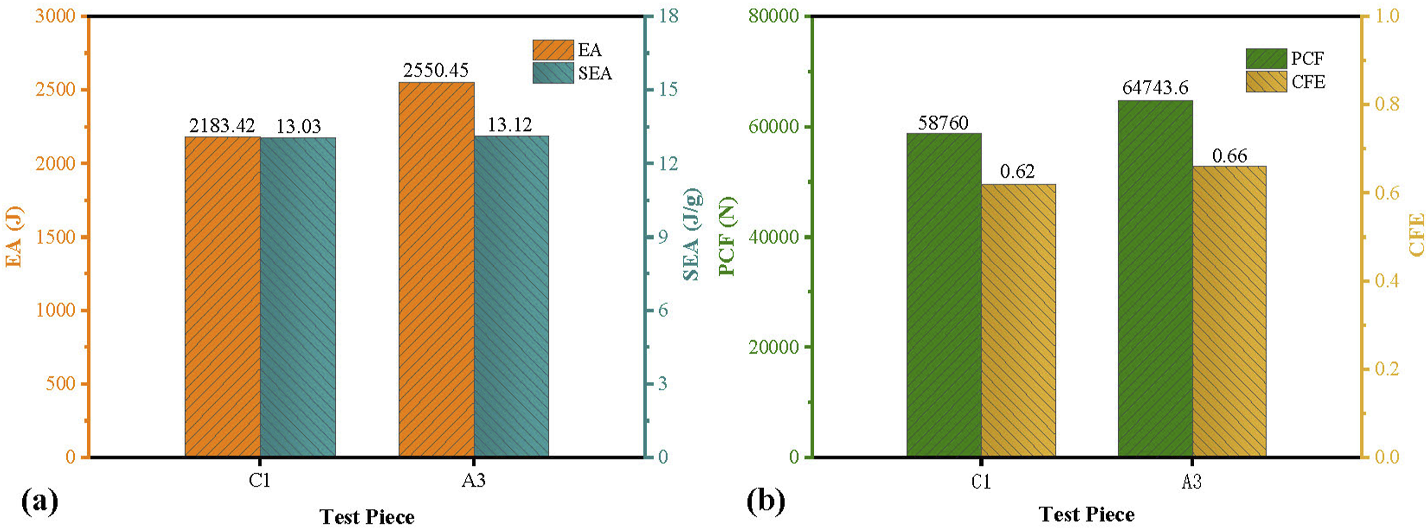
The impact of fiber winding angle
To investigate the effect of fiber winding angle on the energy absorption properties of composite tubes, a study was conducted on the winding angles of fibers within the composite tubes. The design samples considered five different fiber winding angles: [10°, 30°, 50°, 70°, 90°]. Figure 18 depicts the axial compression deformation processes of the samples in Group A. In samples A1 and A2, the CFRP tubes primarily exhibited layered and bundle bending failures, accompanied by fiber rupture, fragmentation, and interlaminar delamination. Due to the layered bending failure of the CFRP tubes and the confinement provided by the internal foam, the metal tubes displayed outward curling deformation. In samples A3 and A4, the primary failure modes included transverse shear damage, layered and bundle bending failures, as well as curling plastic deformation and stacking deformation of the metal tube. Sample A5 demonstrated a stable progressive stacking state. As the fiber winding angle increased, the deformation of the composite tubes transitioned from layered bending failures and curling plastic deformations of the CFRP tubes to transverse shear damage and progressive folding deformation, thus enhance deformation stability of the composite tubes. Axial compression deformation processes of the Group A samples.
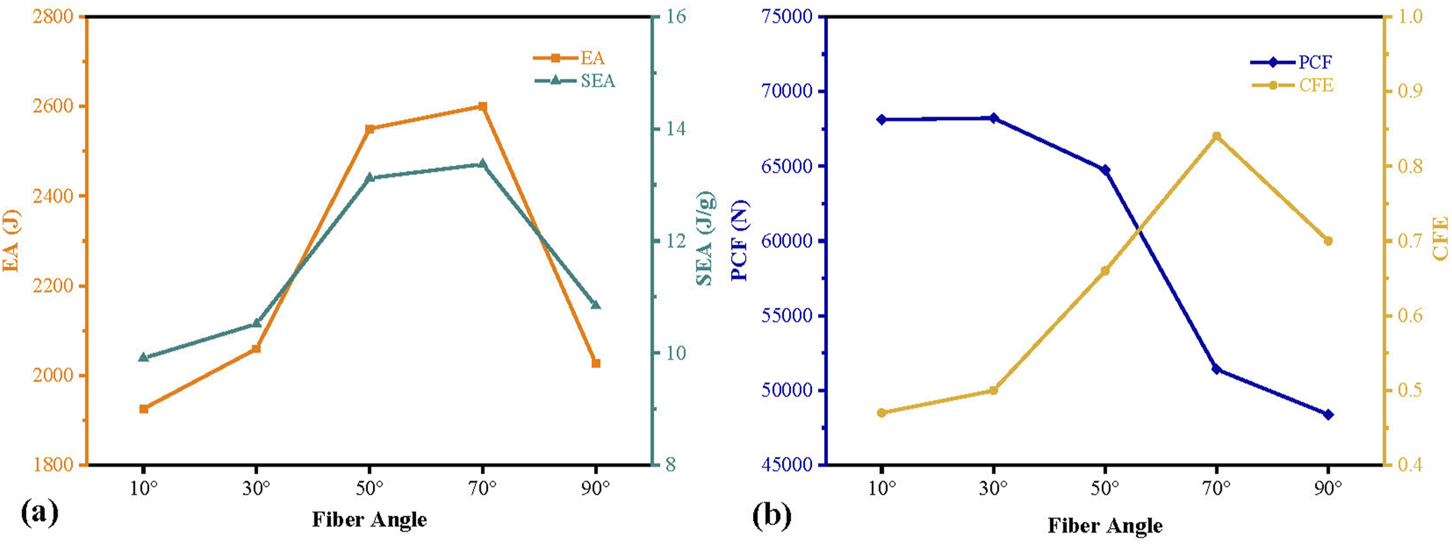
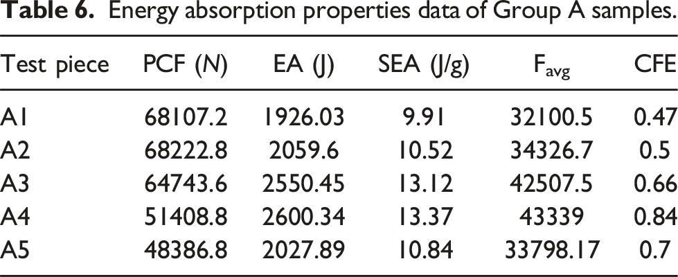
Figure 19 displays the load-displacement curves for the axial compression of the Group A samples. It can be observed that the A1 and A2 samples experience two significant fluctuations in load after a compression displacement of 25 mm. These fluctuations are primarily attributed to the tearing and bending failures of the CFRP pipe and mental tube, leading to subsequent instability in the composite tube. When the fiber winding angle (θ) is ≥ 50°, the load-displacement curves exhibit regular oscillations. These oscillations become repetitive with increasing displacement until the tube reaches a densification stage. Figure 20 illustrates the trends in energy absorption properties of the Group A samples with varying fiber winding angles. As the fiber winding angle changes, both the total energy absorption and specific energy absorption exhibit a peak-shaped variation, reaching their maximum at θ = 70° . The initial peak load decreases with increasing winding angle, while the collision force efficiency initially increases and peaks at θ = 70° before subsequently decreasing. These observed trends are primarily due to variations in the fiber winding angle. As the angle decreases, fibers are oriented axially along the thin-walled tubes, which enhances the axial stiffness and strength of the tube. Consequently, this results in a higher initial peak load. However, the CFRP pipe is more prone to layer-bundle bending failure, leading to lower collision force efficiency. As the fiber winding angle increases, the fibers are oriented circumferentially along the thin-walled tubes, which enhances the circumferential stiffness and strength of the composite tube. Consequently, the initial peak load decreases. Under these conditions, the CFRP pipe becomes more susceptible to lateral shear failure, with cracks predominantly forming parallel to the fiber direction and involving fiber and matrix rupture. This improves the overall material utilization, leading to increased total energy absorption, specific energy absorption, and collision force efficiency for the composite tube. However, when θ = 90°, the lack of axial fiber support in the CFRP pipe results in a relatively unstable crushing process. As evidenced by the load-displacement curve for the A5 sample in Figure 19, the overall load fluctuations are more pronounced compared to the A3 and A4 samples. Table 6 summarizes the energy absorption properties data of the Group A samples. Load-displacement curves for axial compression of Group A samples. Trends in energy absorption properties of the Group A samples during crushing; (a) Trend of EA and SEA of Group A samples; (b) Trend of PCF and CFE of Group A samples. Energy absorption properties data of Group A samples.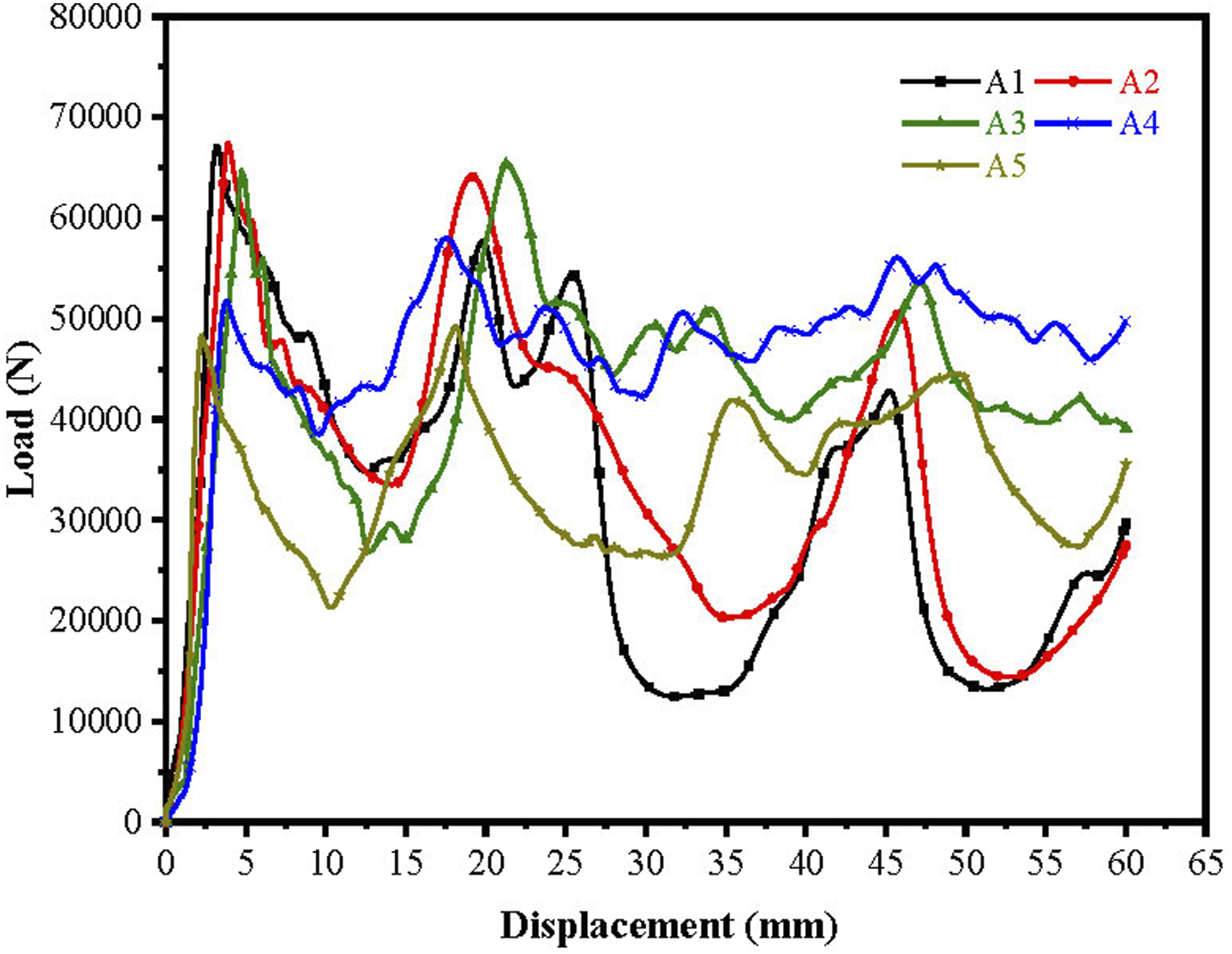
Impact of fiber axial and circumferential winding angles
The study of fiber winding angles reveals that both axial and circumferential fiber orientations significantly impact the energy absorption properties of composite tubes. In this research, the effect of varying the ratio of circumferential fibers (90°) to axial fibers (10°) on the CFRP tubes was investigated. Four different layup ratios were designed for the samples: circumferential (90°) to axial (10°) ratios of 0, 1/3, 2/3, and 1, corresponding to samples B1, A1, B2, and A5, respectively. The objective was to evaluate how these axial and circumferential winding angles affect the energy absorption properties of the composite tubes.
Figure 21 illustrates the axial compression deformation processes of the Group B samples. In Sample B1, the CFRP tube primarily experiences transverse shear failure, manifested through transverse fractures of fibers and matrix, as well as fiber pull-out. Due to the interaction between the CFRP tube and the metal tube, tearing occurs at the corners of the metal tube, resulting in outward curling deformation. In Sample B2, the CFRP tube exhibits layer-bundle bending failure, with shear failure causing the fracture of the layer bundles. The metal tube also undergoes outward curling deformation. When the ratio of circumferential (90°) to axial (10°) fibers is relatively low, the influence of the outer metal tube on the CFRP tube during compression becomes more pronounced, leading to increased tearing of the metal tube and enhanced outward curling deformation. Axial compression deformation processes of the samples in Group B.
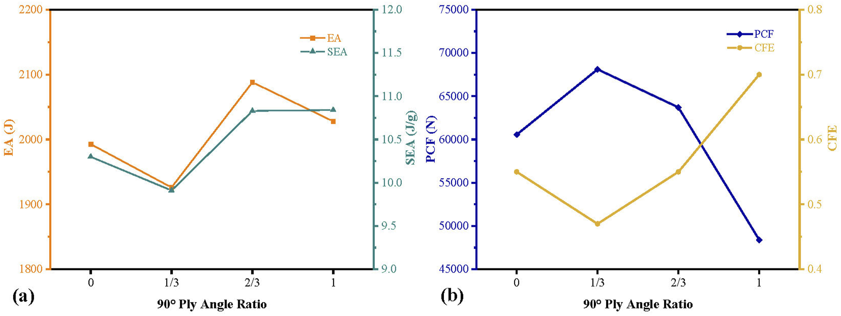
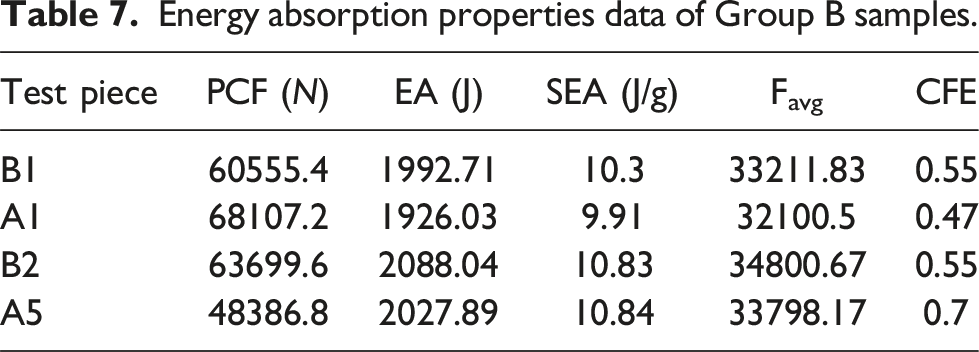
Figure 22 illustrates the load-displacement curves for the Group B samples under axial compression. The curves show comparable fluctuation trends, with the B1, A1, and B2 samples experiencing a marked drop in load and increased fluctuations after a displacement of 25 mm. This decline is primarily due to layer buckling and the outward curling deformation of the metal tube, which result in increased instability during the deformation process. Figure 23 presents the trends in energy absorption properties of the crushed composite tubes. When the circumferential (90°)/axial (10°) ratio is set to 2/3 or 1, the total energy absorption and specific energy absorption of the composite tubes are significantly higher compared to those with smaller ratios. Moreover, an increased ratio results in a reduction of the initial load peak while enhance collision force efficiency, thereby improving the overall energy absorption performance of the composite tubes. Table 7 summarizes the energy absorption properties data of the Group B samples. Load-displacement curves for the axial compression of the Group B samples. Trends in energy absorption properties of Group B samples during crushing; (a) Trend of EA and SEA of Group B samples; (b) Trend of PCF and CFE for Group B samples. Energy absorption properties data of Group B samples.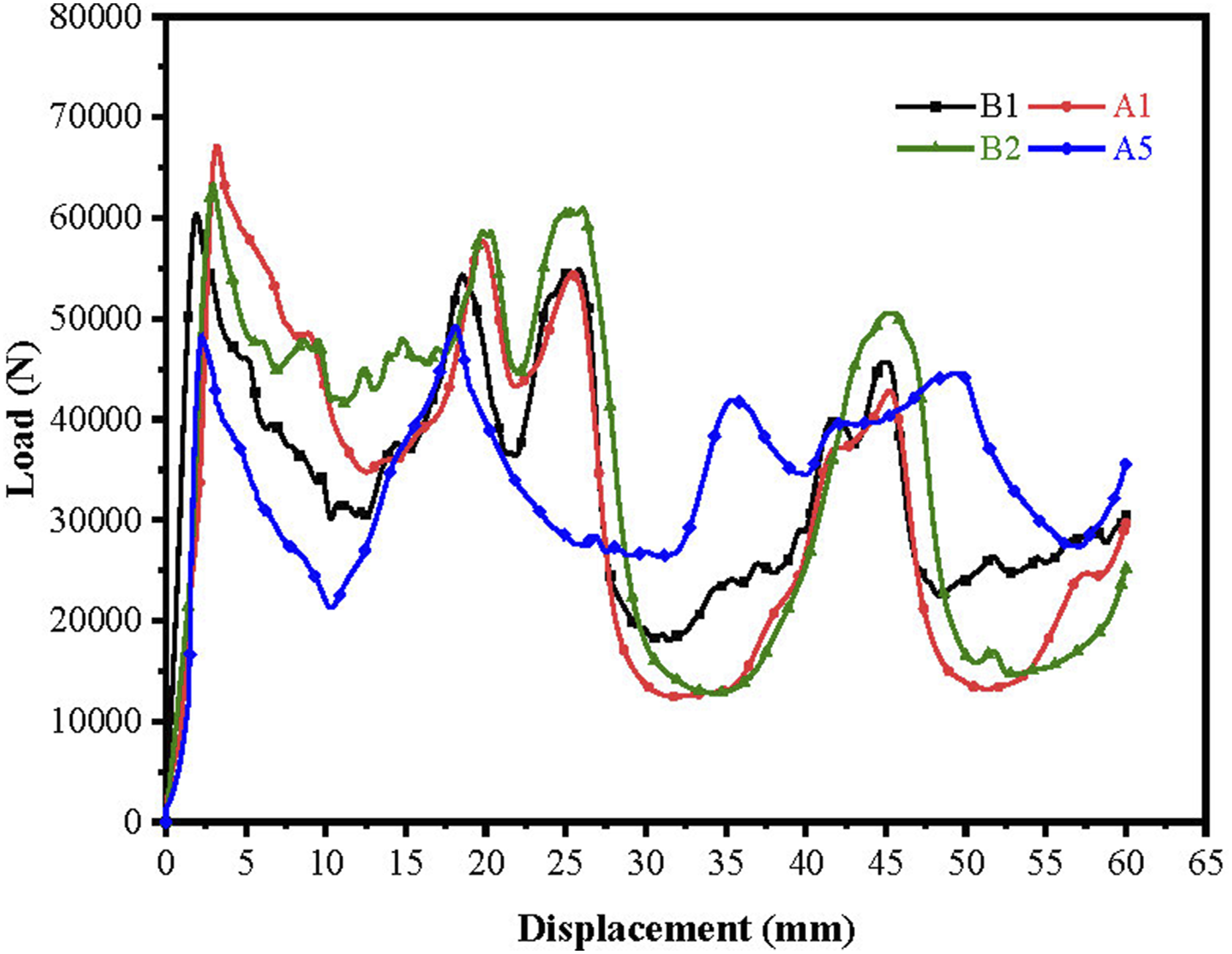
Impact of origami pattern angle on metal tube
The angle of the origami pattern on the metal tube’s wall significantly influences its axial stiffness. Variations in this angle affect the deformation behavior and energy absorption properties of the tube. In this study, metal tubes with origami pattern angles of 140°, 150°, and 160° were designed to investigate how changes in pattern angle impact the energy absorption properties of composite tubes. The corresponding samples, D1, D2, and D3, were prepared with a fixed number of pattern layers, N = 5, while varying the included angle, φ.
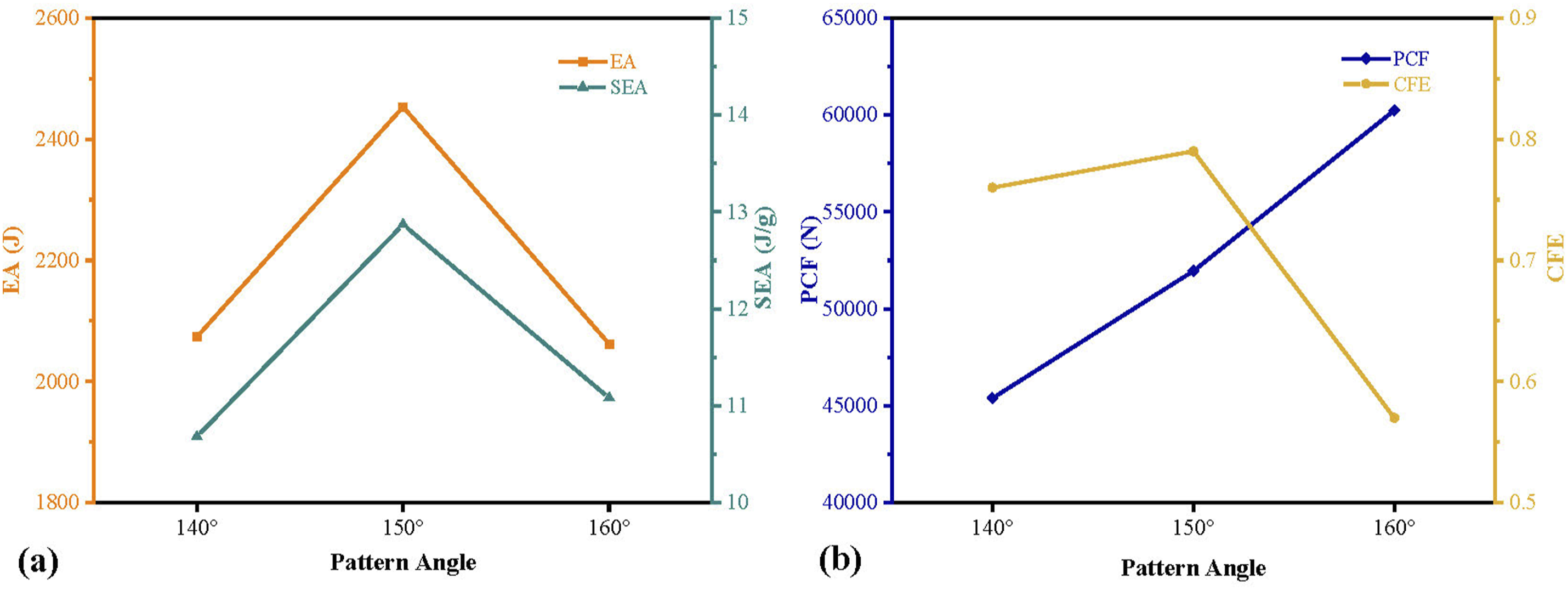
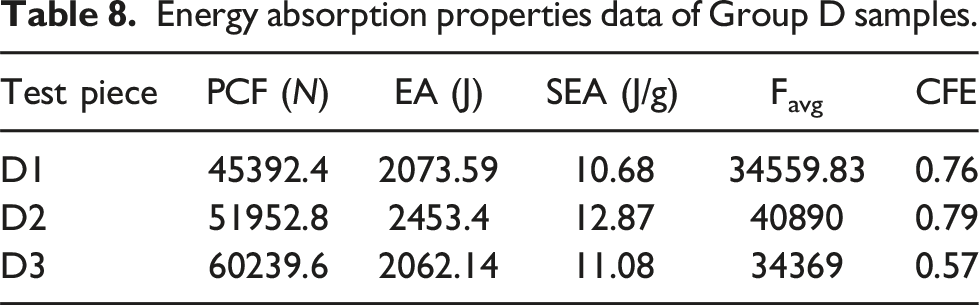
Figure 24 depicts the axial compression deformation of the D-series samples. All three samples exhibit a progressive folding deformation pattern, with the collapse process remaining stable. The composite tube featuring a 140° origami pattern initially forms two concentric, orderly stacking folds. However, as compression progresses, tearing occurs in the central folds, leading to a relatively unstable deformation state in the later stages, though the overall deformation remains predominantly progressive folding. The support provided by the internal polyurethane foam and the plastic deformation of the outer metal tube with the origami pattern contribute to the CFRP tube experiencing transverse shear failure, resulting in a progressive folding deformation state. The failure modes observed include fiber and matrix rupture, fragmentation, and interlaminar delamination. Figure 24(d) depicts the load-displacement curves for the Group D samples. It is evident that as the angle of the origami pattern increases, the stability of the load fluctuations improves, resulting in a more consistent deformation process. Notably, at an origami pattern angle of 150°, the composite tube exhibits superior energy absorption performance, with the load remaining above that of the other two samples during the stable deformation phase. Figure 25 presents the trends in the collapse energy absorption properties of the Group D samples. As the angle of the origami pattern increases, the initial peak load is observed to rise gradually. Both total energy absorption and specific energy absorption, along with collision force efficiency, initially increase with the angle but then decrease, reaching their maximum values at an angle of 150°. Table 8 provides the energy absorption properties data of the Group D samples. Axial compression deformation of the Group D samples; (a–c) Axial compression deformation processes of the Group D samples; (d) Load-Displacement curves for axial compression of Group D samples. Trends in energy absorption properties of group d samples during crushing; (a) Trend of EA and SEA of Group D samples; (b) Trend of PCF and CFE of Group D samples. Energy absorption properties data of Group D samples.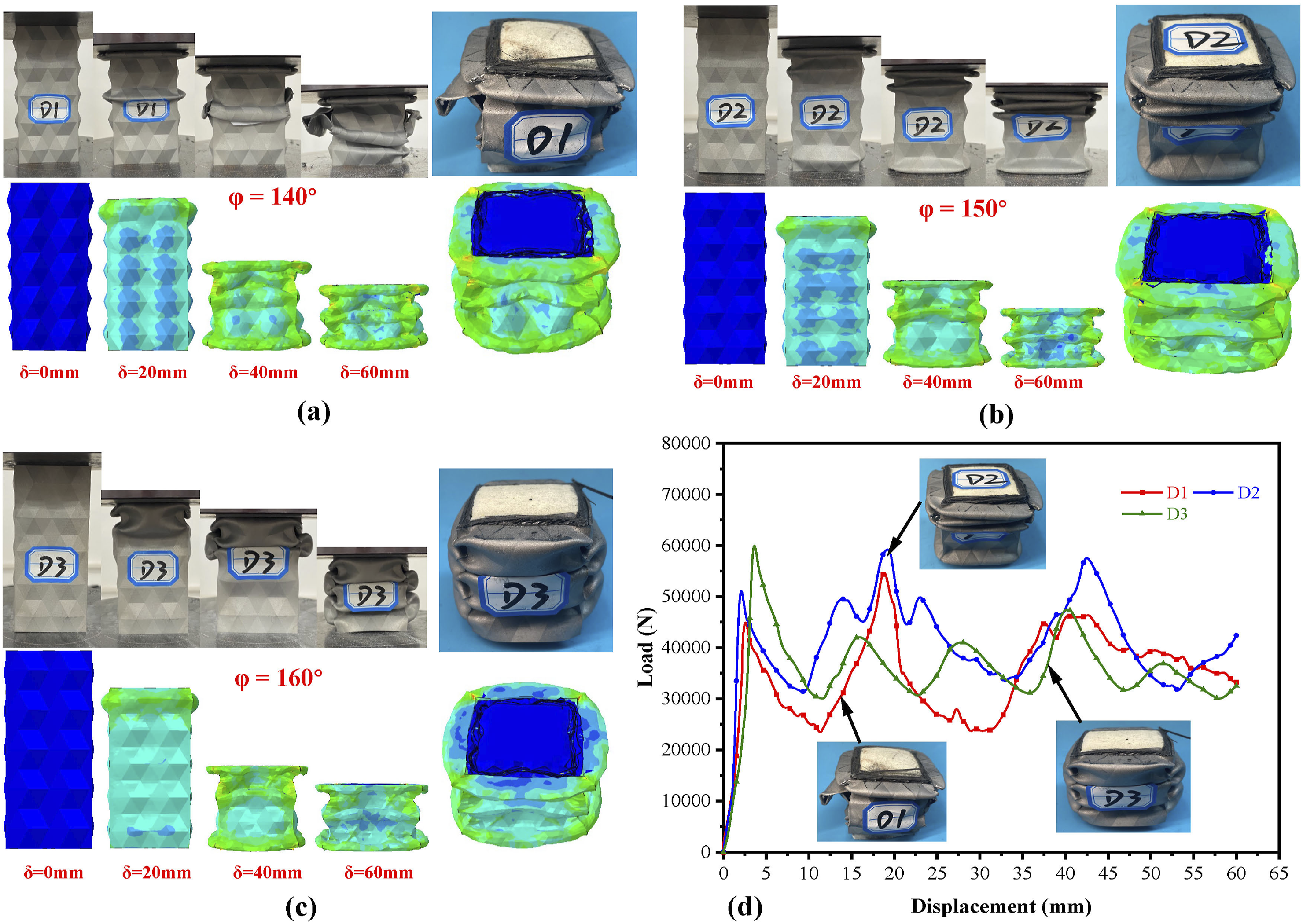
Impact of the number of pattern layers on the metal tube
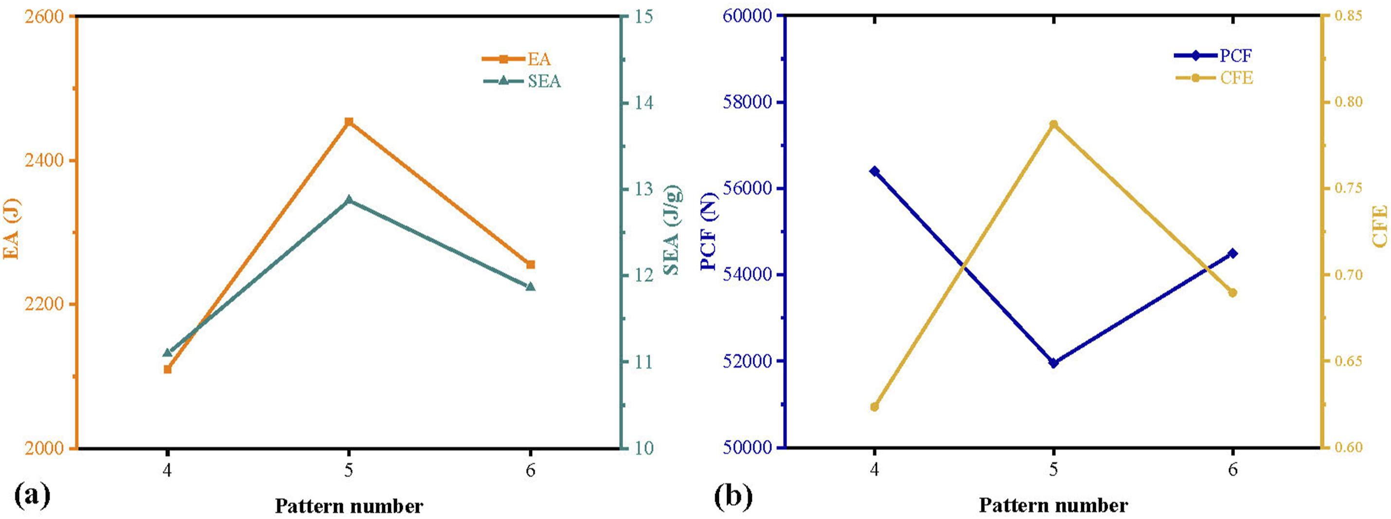
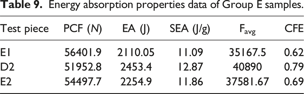
The number of origami pattern layers on the metal tube influences the stacking behavior of the composite tube under axial compression, which in turn affects its energy absorption performance. In this study, the basic number of pattern layers, N, was varied to examine its impact on the energy absorption properties of the composite tube. The samples were designed with N = 4, 5, 6 layers, labeled as E1, D2, and E2, respectively.
Figure 26 illustrates the axial compression deformation of the E group samples. All three samples exhibit a progressive folding deformation state, with a stable collapse deformation process. The E1 sample, with 4 layers of patterns, produces a total of 3 concentric folds. In contrast, the D2 and E2 samples, with 5 and 6 layers of patterns respectively, each produce 4 concentric folds. However, the E2 sample experiences interlaminar compression deformation during stacking, leading to the formation of additional plastic hinge regions compared to the D2 sample. These regions do not fully fold, resulting in insufficient deformation and a lower total energy absorption compared to the D2 sample. Figure 26(d) illustrates the axial compression load-displacement curves for the E group samples. It can be seen that composite tubes with a higher number of origami pattern layers in the metal tube demonstrate more stable load fluctuations. Figure 27 shows the trend of energy absorption properties in the Group E samples. It is evident that when the number of pattern layers is five, the composite tube exhibits the highest total energy absorption and specific energy absorption, even though the initial peak load is the lowest. The crash force efficiency is also observed to be at its highest, indicating optimal energy absorption performance. It can be attributed to the influence of the number of layers on the axial stiffness of the metal tube, as well as the number of folds formed during the progressive collapse of the composite tube. These factors ultimately result in distinct folding patterns and variations in energy absorption properties. Table 9 presents the energy absorption properties data of the Group D samples. Axial compression deformation of the Group E samples; (a–c) axial compression deformation processes of the Group E samples; (d) load-displacement curves for axial compression of Group E samples. Trends in energy absorption properties of Group E samples during crushing; (a) Trend of EA and SEA of Group E samples; (b) Trend of PCF and CFE of Group E samples. Energy absorption properties data of Group E samples.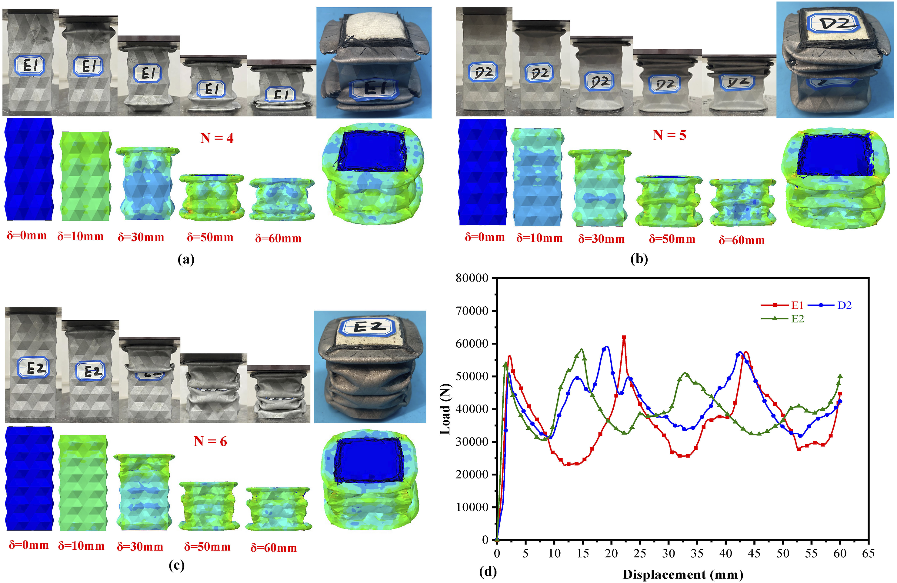
Conclusion
This study investigates the energy absorption properties of thin-walled foam-filled components with metal/CFRP composites and origami patterns under quasi-static compression through both experimental and numerical simulations. The research thoroughly examined the energy absorption properties of metal and composite thin-walled tubes, as well as the effects of foam filling on enhance these properties. In addition, the influence of several design parameters on the energy absorption performance of composite tubes was analyzed in detail, including the fiber winding angle of CFRP tubes, the axial-to-circumferential fiber winding ratio, the dihedral angle of the metal tube patterns, and the number of pattern layers. The following key conclusions can be drawn from this study: (1) The introduction of origami patterns into metal square tubes effectively reduces the peak crushing force (PCF) of thin-walled tubes and alters their deformation mode. The deformation of the metal tube transitions from a non-compact mode to a fully plastic compact mode, where deformation occurs along the origami folds. This modification significantly improves the EA, SEA, and CFE of the metal thin-walled tubes. The PCF of the metal tube decreases by 13.17%, while the EA and SEA increase by 24.4% and 19.24%, respectively. The CFRP tube, due to its lightweight nature, exhibits a high specific energy absorption (SEA); however, it is prone to catastrophic brittle fracture during crushing, which limits its effectiveness as an independent energy-absorbing component. However, combining the metal tube with the CFRP tube effectively improves the energy absorption properties of thin-walled structures. This integration enhances the overall crushing load and stabilizes the load fluctuations. Additionally, the inclusion of polyurethane foam within the CFRP/metal tube significantly improves the deformation stability of the thin-walled tubes, allowing for more efficient progressive folding. The foam provides support during deformation, helping to maintain a consistently high load level throughout the crushing process, which in turn increases the total energy absorption capacity of the composite tube. As a result, the EA is improved by 16.81%. (2) The energy absorption properties of the composite tube are significantly influenced by the fiber winding angle of the CFRP tube. When the fiber winding angle is small, fibers are primarily aligned along the axial direction, which increases the axial stiffness and strength of the tube. In this case, the PCF becomes higher, but the CFRP tube is more likely to experience layer delamination and bending failures, resulting in reduced collision force efficiency. As the fiber winding angle increases, fibers are oriented more circumferentially, enhance the circumferential stiffness and strength of the tube. This configuration lowers the PCF, but the CFRP tube becomes more prone to lateral shear failures, accompanied by fiber and matrix fractures. Nevertheless, the overall material utilization improves, leading to increased EA, SEA, and CFE of the composite tube. As the fiber winding angle increases, the deformation mode of the composite tube transitions from layer delamination and bending failure of the CFRP tube, along with plastic buckling of the metal tube, to lateral shear failure and progressive folding deformation. This shift enhances the stability of the composite tube’s deformation. A larger fiber winding angle results in a lower PCF, while the EA, SEA, and CFE generally increase with the angle. However, these parameters peak at a fiber winding angle of 70° before declining, which is attributed to the influence of the winding angle on the axial and circumferential stiffness and strength of the CFRP tube. (3) The axial and circumferential fiber orientations significantly influence the energy absorption properties of the composite tube. When the circumferential (90°) to axial (10°) ratio is low, the CFRP tube exerts a stronger effect on the outer metal tube during compression, leading to tearing and outward curling deformation in the metal tube, which causes substantial load fluctuations. Under these conditions, the CFRP tube primarily undergoes lateral shear failure as well as layered and bundled bending failure. As the ratio increases, the CFRP tube exhibits fiber pull-out and cracking, and when the ratio reaches its maximum, the composite tube exhibits a stable progressive folding deformation, which results in a reduction in the PCF and an increase in EA, SEA, and CFE. (4) As the angle of the origami pattern in the metal tube increases, load fluctuations in the composite tube decrease, resulting in a more stable deformation process. The interaction between the internal PU foam’s supportive role and the plastic folding of the outer metal tube with origami patterns leads to lateral shear failure in the CFRP tube, which presents as progressive folding deformation. Failure modes include fiber and matrix rupture, fragmentation, and interlaminar delamination. However, excessively large pattern angles result in a higher PCF, followed by a significant drop in load after reaching its peak, leading to lower EA, SEA, and CFE. Overall, an origami pattern angle of 150° provides the optimal energy absorption performance, with well-formed wrinkle stacking and the highest EA, SEA, and CFE, while maintaining a relatively low PCF. (5) The number of layers in the metal tube’s origami pattern is found to influence the stacking behavior of the composite tube under axial compression. As the number of layers increases, a relatively more stable deformation state is observed. However, under the same stacking displacement, interlaminar compression deformation is more likely to occur, leading to the formation of additional plastic hinge regions. These regions are unable to fully fold, resulting in incomplete deformation and reduced energy absorption. The increase in layer count also impacts the axial stiffness of the metal tube, ultimately yielding less favorable energy absorption outcomes according to the evaluation criteria. When the number of layers reaches five, the composite tube exhibits the highest EA and SEA values while maintaining the lowest PCF, indicating superior energy absorption performance and achieving the highest CFE.
Footnotes
Declaration of conflicting interests
The author(s) declared no potential conflicts of interest with respect to the research, authorship, and/or publication of this article.
Funding
The author(s) disclosed receipt of the following financial support for the research, authorship, and/or publication of this article: This work is supported by the China Postdoctoral Science Foundation (Certificate Number: 2024M754115).
Data availability statement
Data sharing not applicable to this article as no datasets were generated or analyzed during the current study.