
Abstract
This study utilizes the Split Hopkinson Pressure Bar (SHPB) technique to investigate the impact compressive behavior of carbon nanotube (CNT)/carbon fiber reinforced composites under high strain rate loading. The impact-induced compressive damage evolution was characterized through SHPB testing, while synchronized high speed photography capturing real-time deformation and the fracture process, revealing correlations between internal crack initiation/propagation and stress variations. The results demonstrated that carbon fibers enhance the composite initial modulus while retaining the high-toughness characteristics of the CNT/epoxy matrix. Notably, the internal structural failure time was extended by 157%. The integration of SHPB testing with high-speed photographic observation provides a robust framework for analyzing the internal impact-induced compressive damage evolution, offering valuable insights for evaluating the dynamic behavior of other fiber-reinforced composites.
Keywords
Highlights
• Combined SHPB with high-speed photography for synchronized analysis. • Carbon fibers enhanced modulus and maintained CNT/epoxy matrix toughness. • Prolonged internal structural failure time by 157%.
Introduction
In recent decades, fiber-reinforced composites have been increasingly applied in the automobile and aerospace fields due to their light-weight, high-strength, and high-modulus properties, making them superior as to traditional materials. 1 During use, these materials have a high demand for impact-compression performance. To develop more reliable light-weight fiber-reinforced composites, it is essential to investigate the internal damage evolution process of fiber-reinforced composites under impact-compression loading. 2 Scholars have long discussed experimental techniques for evaluating the dynamic properties of fiber-reinforced composite materials, especially the impact of high strain rates on these properties. 3 Scholars have explored several methods for characterizing the dynamic properties of composite materials and explained the development of drop weight impact and Hopkinson bar systems for dynamic characterization of composites under compression and shear at high strain rates. 4 The Split Hopkinson Pressure Bar (SHPB) test technique has emerged as a primary experimental method for investigating the mechanical behavior of composite materials under dynamic loading conditions, particularly at high strain rates. 5
The fundamental principle of the SHPB testing technology involves applying force to a specimen by high-speed impact and measuring the stress-strain relationship of materials in a short time through the pressure bar system. This method can evaluate conditions under quasi-static (less than 0.1 s−1) and medium strain rate (0.1-102 s−1), but is mainly used to determine the dynamic stress behavior of polymers at high strain rates (approximately 102-104 s−1).6–8 The SHPB test setup typically consists of an incident rod, a transmitted rod, and a striker. The striker, often a high-speed projectile, impacts the incident rod. The specimen is placed between the incident and transmitted rods. When the striker hits the incident rod, it generates an elastic stress wave. A portion of this wave is transmitted to the specimen as an incident wave, causing deformation, while the remaining travels back along the incident rod as a reflected wave. By applying one-dimensional elastic wave theory, stress, strain, and strain rate can be calculated from the measured elastic stress waves in the rods.9–11 The SHPB was initially designed for the performance study of metallic materials. SHPB testing faces challenges in analyzing brittle materials due to difficulties in achieving stress equilibrium at both ends of the specimen, as brittle materials tend to fracture at small strains. The stress-strain relationship of the material is determined by ensuring stress balance at both ends of the specimen. This poses a challenge to the use of SHPB for brittle materials. However, research indicates that the dynamic stress balance can be maintained by controlling the incident wave.12,13 The testing method of SHPB has also evolved, with some scholars adopting new loading approaches to develop a dynamic Brazilian disc splitting tensile test, which can be used to investigate the dynamic tensile properties and crack extension patterns of materials. 14 During testing, the polymeric composite exhibits pressure sensitivity,15–17 requiring careful assessment of whether SHPB tests can measure the true strain-rate dependence of polymers at high strain rates. Some studies have highlighted that beyond the transition strain rate, the stress-strain curves of polymers depend on several factors such as lateral constraint, actual strain-rate, and thermal softening. These influences should not be mistaken for pure strain-rate effect.18–22 Over time, the drawbacks of SHPB testing technology in different material fields have been gradually overcome.
However, using the average nominal values of stress, strain, and strain-rate to evaluate the impact-compression performance of fiber-reinforced composites is questionable. Compared to materials such as concrete, metal, and ice,23–25 the stress changes in fiber-reinforced composites under high-speed impact are more complex. If the stress difference at the sample end is too large, relying on average nominal values for stress-balance calculations will result in significant errors. To verify the reliability of SHPB strain data, theoretical calculations alone are insufficient. Koerber et al. 26 experimentally investigated the strain-rate effects on polymeric matrix composites. Using high-speed cameras for dynamic experiments to monitor the specimen failure process, the reliability of SHPB experiments was effectively verified. As capturing the deformation process with a high-speed camera is essential for observing internal cracks. Researchers can accurately assess the compressive stress - strain behavior and fracture behavior of fiber-reinforced composites by visually analyzing crack initiation and propagation. 2
This study focuses on the application of the SHPB method in carbon nanotube (CNT)/carbon fiber reinforced composites. It aims to accurately assess the damage evolution caused by impact compression at high strain rates using SHPB tests.
Experimental
Materials
The sample preparation process is illustrated in Figure 1. The resin matrix used was a modified bisphenol A-type epoxy resin, while the curing agent was a modified cycloaliphatic amine. Both were purchased from Youfeng New Materials Co., Ltd, China. The amino-functionalized multi-walled CNTs with a purity of 99% were obtained from China Carbon Technology Co., Ltd. The carbon fiber used was 12KT700, purchased from Toray Industries, Japan. Preparation process of Sample A, Sample B, and Sample C.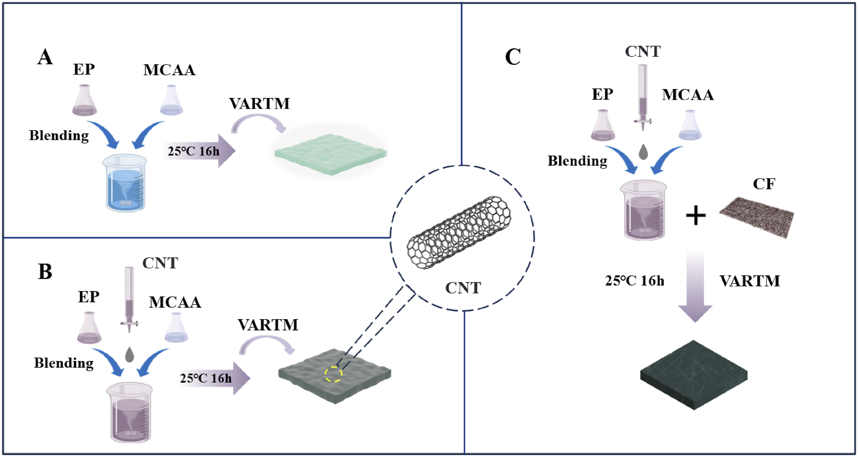
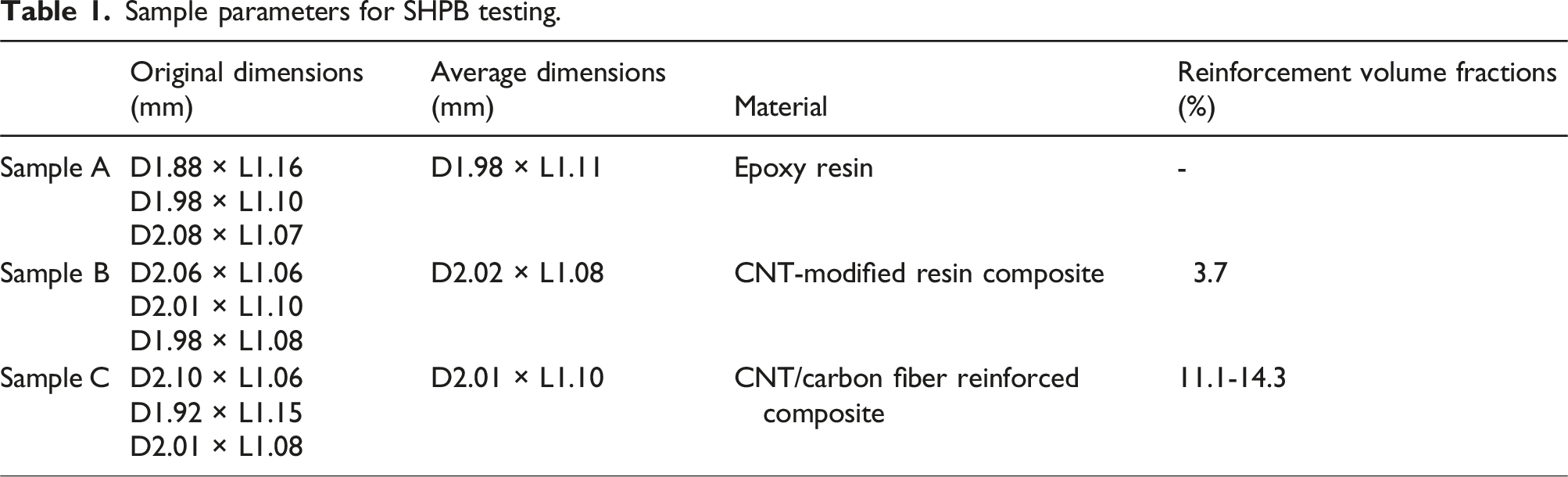
Sample parameters for SHPB testing.
Experimental apparatus
Split Hopkinson pressure bar theory
The traditional SHPB testing system is shown in Figure 2. Its experimental principle is based on the propagation characteristics of strain waves. By analyzing the strain wave propagation along the pressure bars and applying the one-dimensional wave theory, i.e., the one-dimensional stress assumption of the bars and the assumption of uniform stress and strain, the average stress and strain values of the specimen can be determined. The primary function of this system is to obtain the dynamic constitutive response of materials under high strain-rate conditions and generate the stress-strain curves with strain-rate as the parameter. Principle diagram of the SHPB.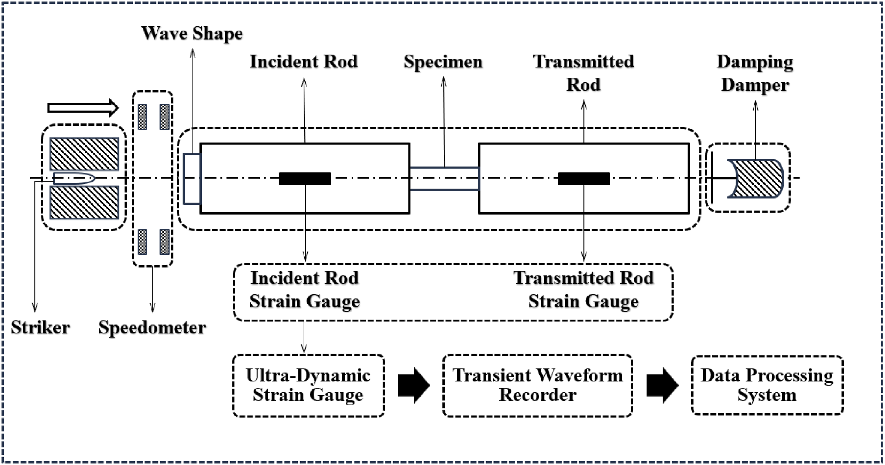
In this system, three pulse signals are recorded: the incident wave
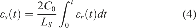
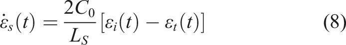
According to the one-dimensional stress wave theory or the assumption of uniform stress, there is a formula regarding strain ( 

If the two-wave method using the incident and reflected waves is employed to calculate stress and strain, then: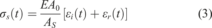
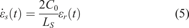
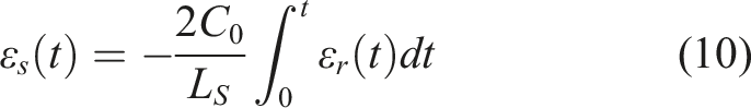
If the two-wave method using the incident and transmitted waves is employed to calculate stress and strain, then: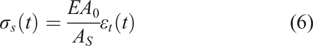
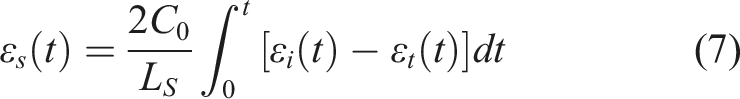
If the two-wave method using the reflection and transmission waves is employed to calculate stress and strain, then: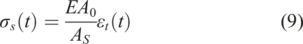
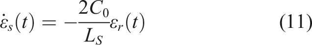
If the three-wave method using the incident, reflected, and transmitted waves is employed to calculate stress and strain, then: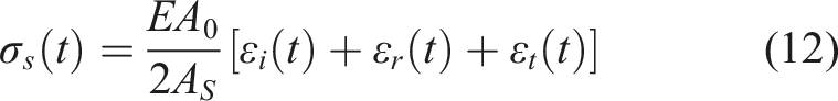
When dynamic equilibrium is achieved, the appropriate formula is selected based on the material properties of the specimen for calculation. The reflection wave of the specimen material is more susceptible to interference factors, compared to metallic material specimens. Polymers , in particular, exhibit lower stiffness and are highly sensitive to test temperature and strain rate. 22 In this experiment, the two-wave method was used under the assumption that the stress waves at all points in the incident and transmission bars were known and that the stress and strain in the specimen were uniformly distributed along its length. During this impact, the strain gauge data from the incident and transmission bars were collected to estimate the subsequent calculation data.
SHPB and rapid imaging system
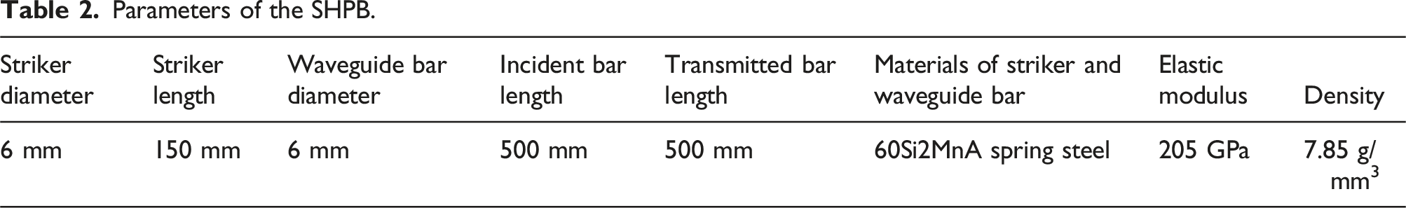
Parameters of the SHPB.
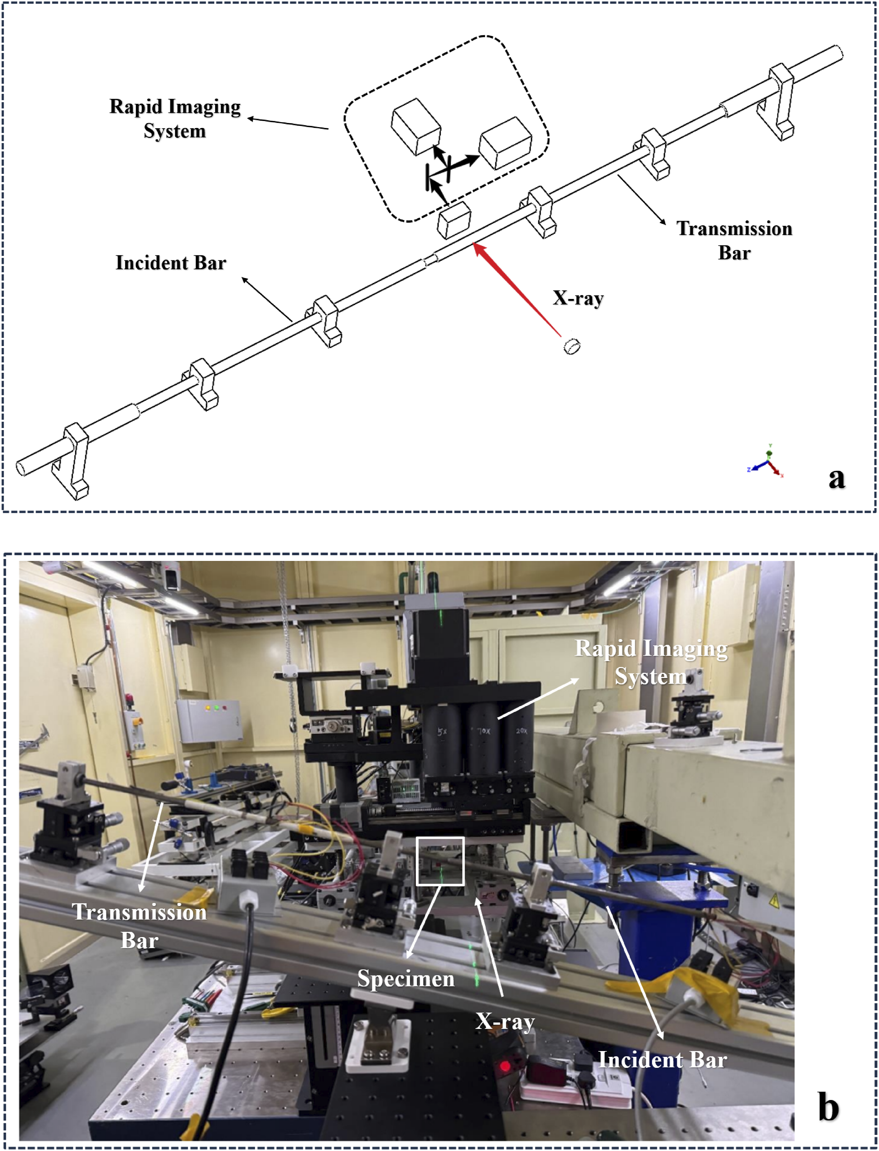
(a) Schematic of the SHPB and rapid imaging system setup, (b) photograph of the SHPB and rapid imaging system setup.
Before conducting the experiment, strain gauges are bonded to the incident bar and the transmission bar to detect strain variation in specimens during experiments. These strain gauges have a gauge length of 2 mm, a resistance of 120 Ω, and a sensitivity coefficient of 2.12. The areas for strain gauge adhesion on the incident and transmission bars were sanded in an arc shape (wider than the strain gauge area) using sandpaper, followed by cleaning. The adhesion areas were wiped in one direction with materials such as degreased cotton, gauze, and wrinkled paper soaked in high-volatility solvents like acetone. Alignment was made at the strain gauge adhesion positions. The surface (metal foil part) and back of the strain gauges were carefully inspected. A drop of adhesive was applied to the back of each strain gauge, which was quickly attached to the designated area. A polyethylene film was placed over the strain gauge, and pressure was applied with the thumb to press the strain gauge onto the bar for about 3 minutes. Once the adhesive hardened, the polyethylene film was removed, and the adhesion status was checked to complete the strain gauge application. Dupont wires were soldered to the strain gauges as extension wires and connected to the bridge box. A multimeter was used to verify that the strain gauge resistance was 120 Ω (±1 Ω). Afterwards, the bridge box cable was connected to the strain meter, which was then linked to an oscilloscope. The strain gauge was calibrated and set to the 1k range, with a magnification of 100x for resistance strain gauges and 40× for semiconductor strain gauges. The filter was adjusted based on on-site noise levels. The oscilloscope settings were optimized according to the air pressure condition, with a sampling rate greater than 100 MHz and a time base of 100 μs/div.
Before conducting static and dynamic imaging tests, the system was thoroughly debugged. First, the Hopkinson bar loading platform was assembled, followed by the fine-tuning of the fast X-ray imaging optical path. The sample position was adjusted using an electric-controlled displacement stage to ensure that the X-ray spot was aligned with the green light in the central area of the sample. Next, coaxiality was verify by conducting experiments without the sample to detect the incident and transmitted wave states. After the states were normal, the tests were prepared for.
High-speed impact testing with SHPB
The experiment was conducted at room temperature (25°C) and under standard atmospheric pressure. The experimental parameters were set according to Table 2. First, static imaging tests were performed on the three types of specimens, mainly to evaluate the surface quality of the sample materials. The specimens were placed between the incident and transmitted bars, and the sample position and imaging quality were adjusted through static photography. This process also enabled the observation micro-defects in the samples. To ensure accurate high-speed impact experimental data, a signal delay generator was used to synchronize the Hopkinson bar, the fast X-ray detection system, and the X-ray light on time (opening and closing of the fast and slow shutters).
In this test, static imaging acquisition was first performed on samples A, B, and C individually, with an image acquisition interval of 3.75 μs. Static raw imaging of the three samples was obtained using a 13 mm Al filter and a long exposure of 10 seconds. Subsequently, SHPB high-speed impact tests were conducted. The deformation process of the samples under Hopkinson bar loading was captured using a fast X-ray imaging system at an interval of 3.75 μs, acquiring corresponding two-dimensional image data. Meanwhile, background images of the X-ray source and noise background images of the detection system were collected. During the impact process, the strain gauge data from the incident and transmission bars were recorded to facilitate the subsequent calculation data. Additionally, for Sample C, the primary focus of this experiment is to test its lateral compressive strength in the out - of - plane direction of the laminate.
Raw wave processing
When using the SHPB device for high - speed impact testing in this study, the collection of raw data was significantly affected by noise and typical Pochhammer-Chree (PC) oscillations. To minimize the effects of high frequency oscillations, lateral inertial effects, and wave form dispersion, filtering of the raw wave form signals was necessary.
33
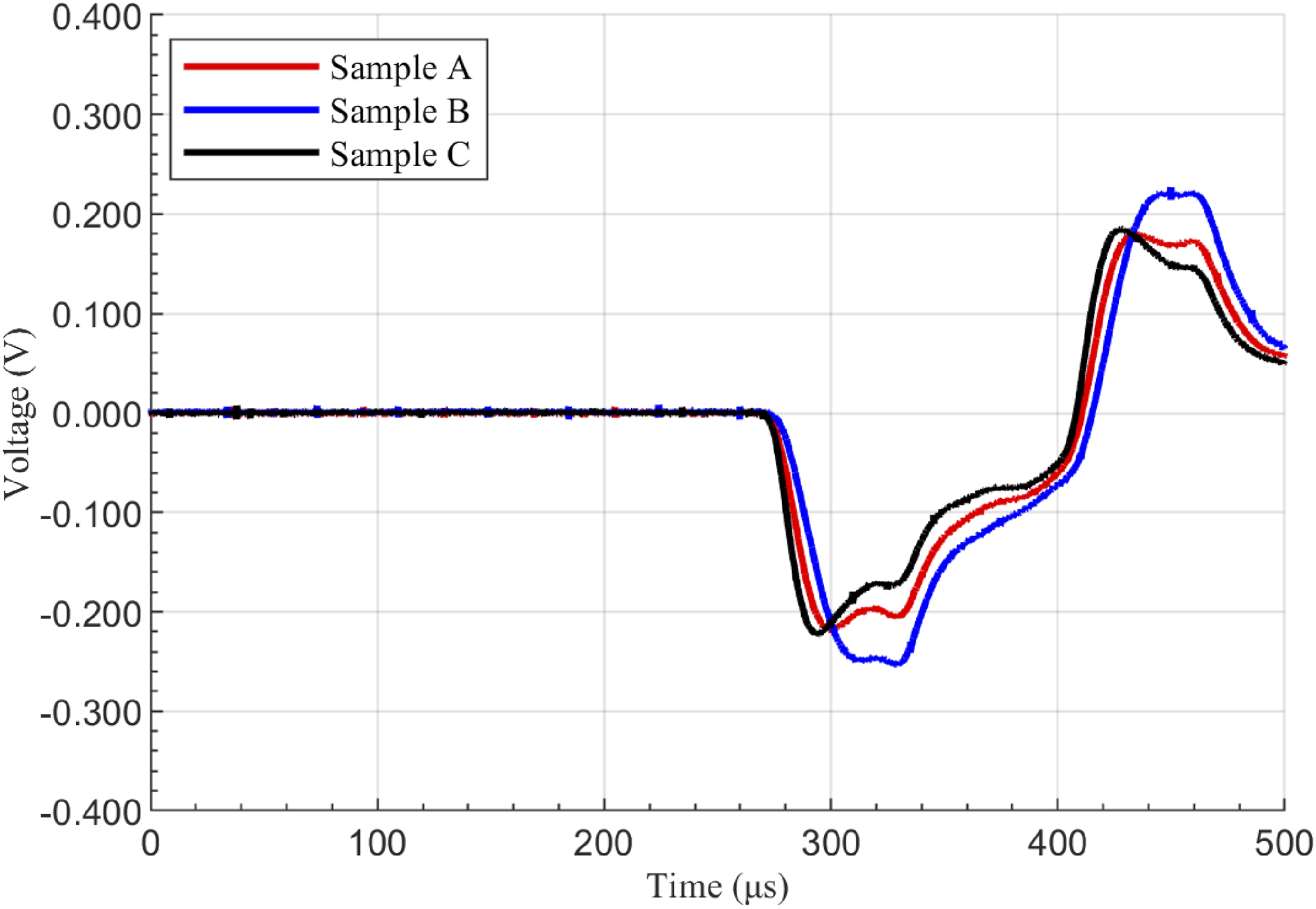
A 1 MHz filter was applied to eliminate high frequency electrical noise, most of the high - frequency noise and external interference were effectively removed. Finally, the incident and reflected waves of the three different samples were obtained, as shown in Figure 4, and the transmitted waves are shown in Figure 5. Filtered incident and reflected wave of signals in SHTB tests. Filtered transmitted wave of signals in SHTB tests.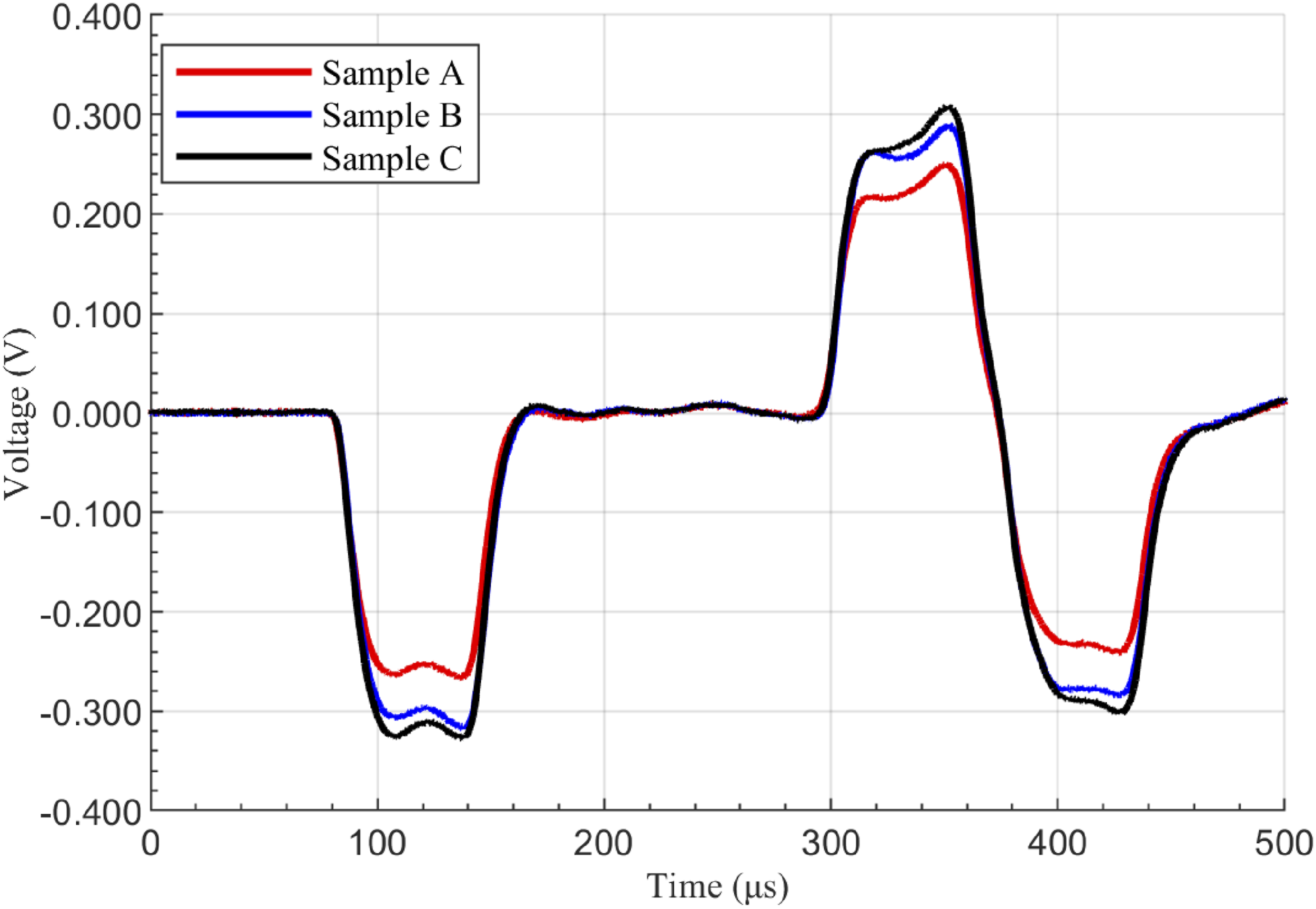
Results and discussion
Stress-strain behavior and fracture observation
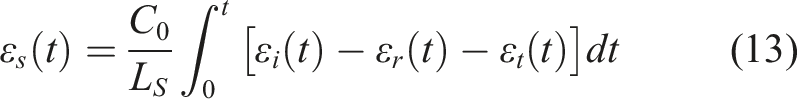
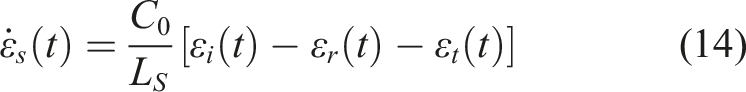
After verifying stress equilibrium using equation (2), the average nominal stress was calculated using equations (9) and (12), while the average nominal strain and nominal strain rate were determined using equations (10) and (11). For ease of analysis, the data were absolute valued and characterized as engineering stress, engineering strain, and engineering strain rate respectively.
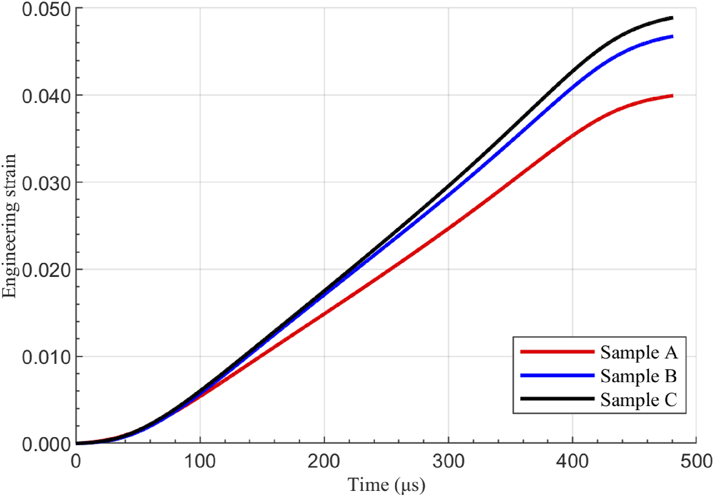
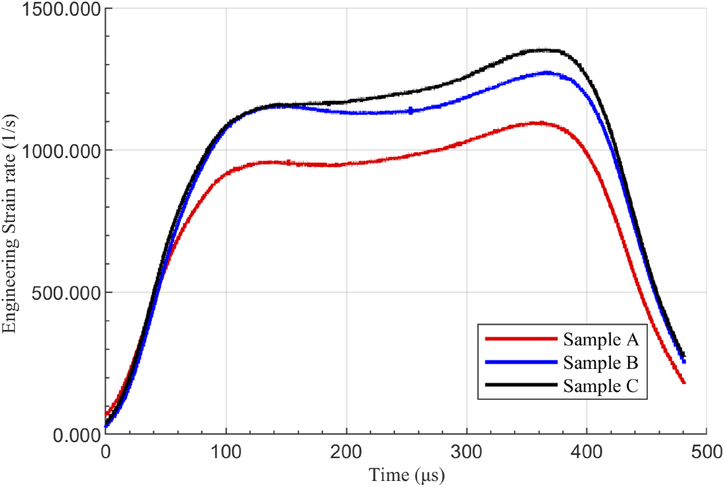
Figure 6 present the engineering stress-time curves of the three materials under high-speed impact. Sample A exhibit slowest stress increase, Sample B has the smallest curve slope, and Sample C demonstrates the fastest stress increase. This indicates that pure epoxy resin has the lowest load bearing capacity, whereas the addition of carbon nanotubes significantly enhances the matrix toughness and reduces the material brittleness. Furthermore, the incorporation of fibers also increases the material modulus. As shown in Figure 7, the engineering strain-time curves indicates that Sample A accumulates slowest strain accumulation, Sample B shows an increased strain rate, and Sample C achieves the fastest strain response. Combined with the strain-rate analysis in Figure 8, it is evident that pure epoxy resin has a limited deformation rate due to its brittleness. However, with the addition of carbon nanotubes, the material toughness can be improved through interfacial enhancement, while the macroscopic support effect of carbon fibers further enhances the composite material with a higher dynamic deformation capacity. This can be attributed due to the multiscale reinforcement mechanism, where synergistic effect of CNTs and carbon fibers optimizes the nanoscale interface while the macroscopic fibers contribute to load bearing. Consequently, the composite material to have high compressive strength, excellent toughness, and dynamic stability under high-speed impact. Stress–time relationships of the samples obtained through SHTB tests. Engineering compressive strain–time relationships of the samples obtained through SHTB tests. Strain rate–time relationships of the samples obtained through SHTB tests.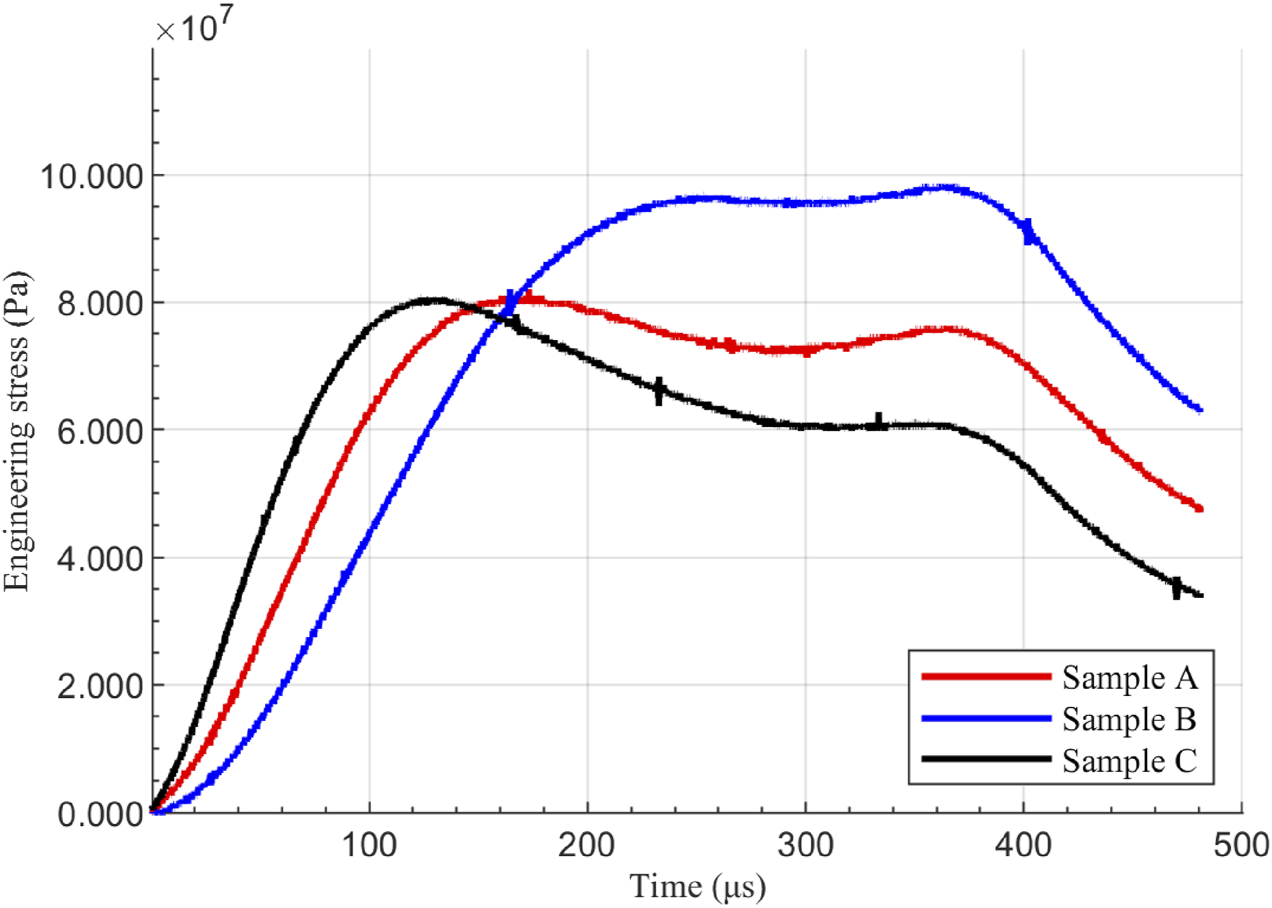
For easier observation, the images underwent post-processing to be horizontal. As shown in Figure 9, the deformation and fracture states of the three samples starting from 0 μs are illustrated. For each sample, three representative images were selected based on the entire deformation process to assist in analyzing the deformation of the samples at different stages. The figure clearly shows the process of crack formation and final failure of the samples under compressive load. Sample A (pure epoxy resin) experienced crack initiation and stable propagation at 67.5 μs, entered the unstable propagation stage at 262.5 μs, and the material was completely fractured. Sample B (epoxy resin/CNT) had multiple coexisting cracks at 157.5 μs without structural collapse, and the material was essentially fractured at 390 μs. For Sample C (epoxy resin/CNT/carbon fiber), local micro cracks formed at 262.5 μs, and the material was essentially fractured at 412.5 μs. It is evident that there are significant differences in the failure times of the three materials. Specifically, compared to Sample A, the structural failure time of Sample B was extended by 149%, while that of Sample C was extended by 157%. In combination with Figures 6–8, it can be found that the maximum compressive stresses experienced by Sample A, Sample B, and Sample C at failure were 80.5 MPa, 98.5 MPa, and 81.3 MPa, respectively. After 157.5 μs, the strain rate of Sample C was higher than that of Sample B, while the strain rate of Sample A was the lowest and remained so until the end of the test. It can be clearly observed that, compared to Sample A, the compressive properties of Samples B and C have been enhanced. Dynamic deformation and fracture evolution of specimens in SHTB tests: A (Sample A), B (Sample B), and C (Sample C). Representative 2D images of the three samples were selected, including the static sample image at 0 μs, the image with numerous cracks, and the final image of complete compressive failure.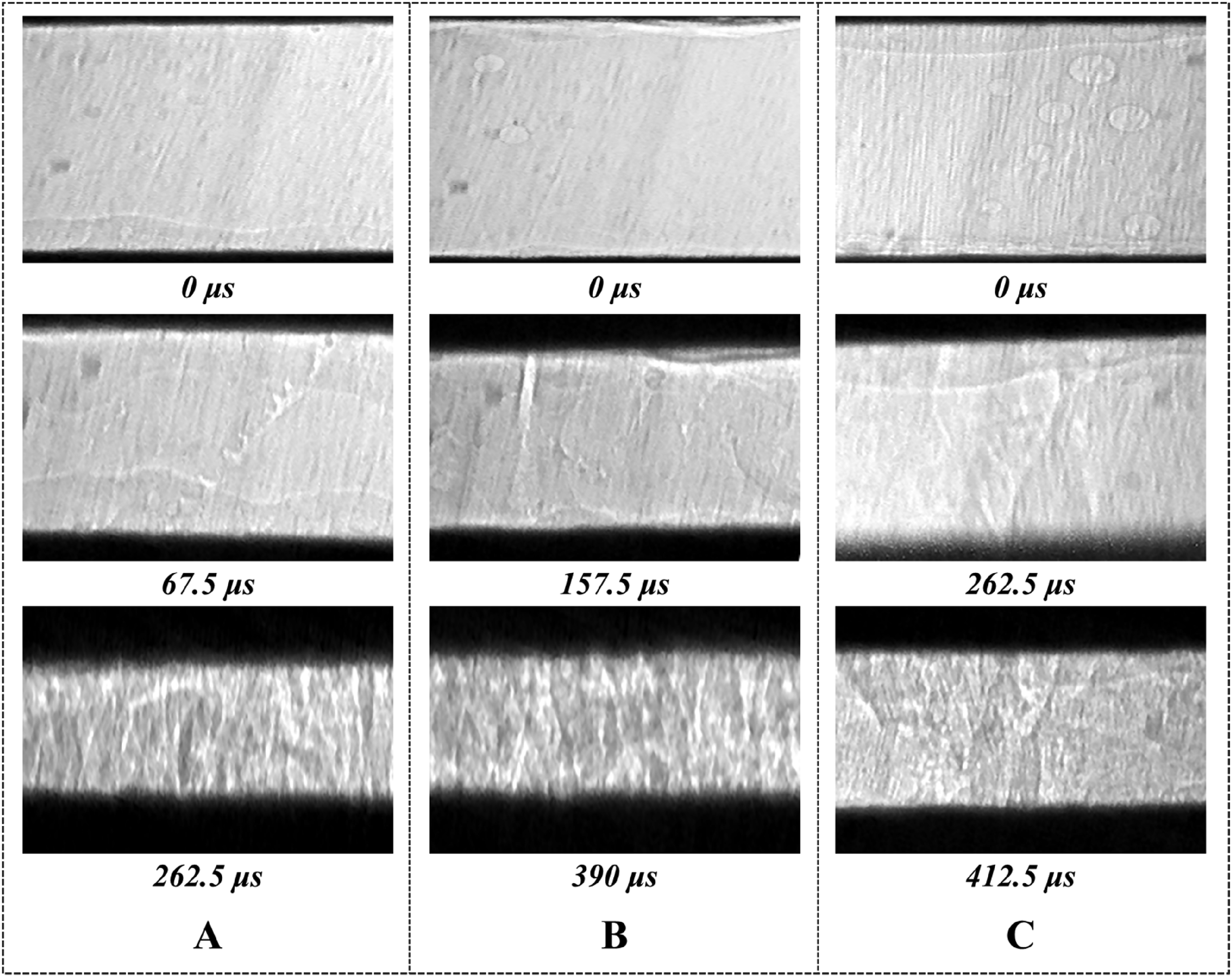
There are several hypotheses regarding the enhancement mechanisms of the compressive properties of composite materials. Firstly, the bridging effect of CNTs can pin crack tips and induce crack deflection, thereby increasing the crack propagation path length and ultimately enhancing the fracture energy of the composite. Secondly, carbon fibers have a multi-level toughening mechanism, including fiber-matrix interface debonding and fiber pull-out, which can significantly increase the material fracture energy. Lastly, there may be a multiscale synergistic effect, where CNTs optimize stress distribution at the nanoscale, while carbon fibers establish a load-bearing network at the macroscale, effectively enhancing crack propagation resistance. By constructing a multi-level reinforcement system of nanotubes and microfibers, the crack propagation rate of composite materials is significantly reduced, and the structural failure time is extended by 157%. Simultaneously, the maximum compressive stress was enhanced. This confirms the crucial role of multiscale synergistic design in enhancing impact resistance.
Stress–strain relationship
The stress-strain curves of the three materials shown in Figure 10 reveal a consistent trend: after reaching the peak stress, stress gradually decreases regardless of the strain rate. It can be observed that the stress-strain curve of Sample A drops sharply after reaching a peak stress of 80.5 MPa, indicating poor ductility, low energy absorption capacity, and low toughness, which aligns with the brittle nature of pure epoxy. The ultimate maximum failure stress of the epoxy/CNT composite is 98.5 MPa. After the stress peak, the curve decreases slowly and the area under the curve is larger, showing that CNT addition enhances the material plasticity and energy absorption. This improvement is likely due to CNTs pinning crack tips and inducing crack deflection, boosting crack resistance and delaying failure. The maximum fracture stress of the epoxy/CNT/carbon fiber composite is only 81.3MPa. This may result from low carbon fiber volume content and weak interfacial bonding, but the curve decreases most slowly after the peak, and the area under the curve is relatively large. This indicates the composite retains some high-toughness features of CNT-enhanced composites despite interfacial effects. Stress–strain relationship of the samples obtained through SHTB tests.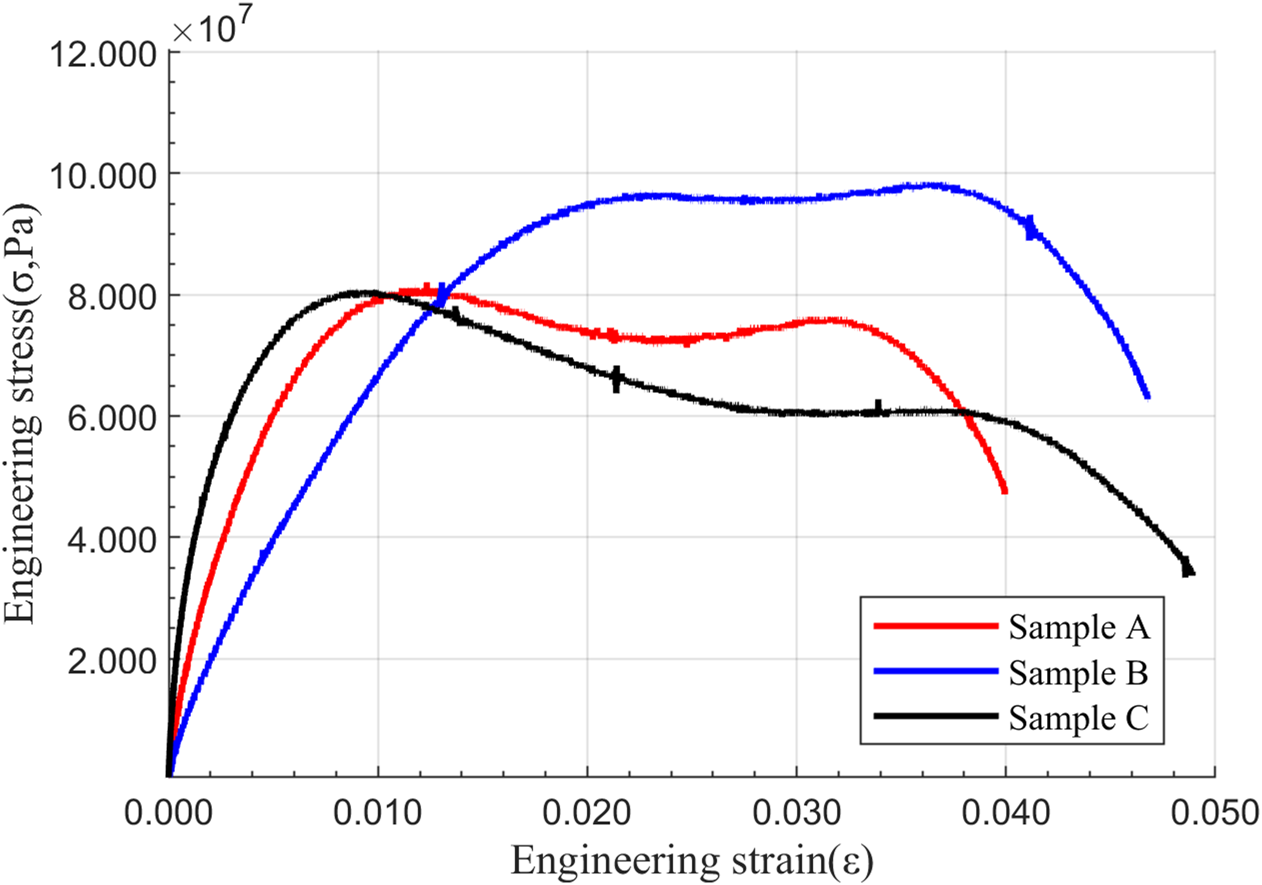
From Figures 7 and 8, the average strain rates of the three samples were similar within 0-67.5 μs. After 67.5 μs, Sample A average strain rate was much lower than the others. After 157.5 μs, Sample C average strain rate exceeded that of Sample B. During the period from the start until complete failure, the maximum average strain rates were 1090 for Sample A, 1430 for Sample B, and 1750 for Sample C. Within 67.5 μs, the Engineering compressive strain of all three samples was nearly 0.002. Within 157.5 μs, the Engineering compressive strain of Samples B and C was approximately 0.008. These findings highlight the significant differences in toughness among the three samples. Clearly, the synergistic effect of CNTs and carbon fibers further enhances the composite compressive strength. Carbon fiber addition provides extra load-bearing capacity, enabling better stress dispersion and delayed crack propagation during compression, thus slowing down the failure process.
Effect of reinforcements on impact-compression properties
The selection and distribution of reinforcements within the matrix significantly influence the impact-compression properties of composites materials. It is evident that the incorporation of (CNTs and carbon fibers) can greatly enhance the strength and toughness of the resin matrix. However, if carbon nanotubes and carbon fibers are not evenly distributed in the matrix material, it may lead to stress concentration, thereby accelerating material failure. Carbon nanotubes can improve the ductility of materials, but the enhancement of mechanical properties may be limited. In this experiment, the addition of carbon fibers significantly improves the mechanical properties of the material. However, an excessive amount of carbon fibers could lead to an increase in material brittleness, ultimately reducing its impact resistance. Finally, the interfacial bonding strength between reinforcements and the matrix also has an important impact on the mechanical properties of the material. High interfacial bonding strength can fully utilize the role of reinforcements, while low interfacial bonding strength may lead to debonding between reinforcements and the matrix, thereby compromising the overall performance of the material. In summary, the addition of reinforcements does not automatically extend the failure time of the structure. The specific impact depends on several factors, including the type, content, dispersion, and interfacial bonding strength with the matrix of the reinforcements. In practical applications, these factors must be carefully considered comprehensively to optimize the performance of the material.
Conclusions
In this experiment, the Hopkinson bar test was primarily utilized to investigate the impact-compression properties of three materials under high strain-rate conditions. A high-speed camera was employed to capture the entire deformation state, facilitating a more realistic observation of the material deformation process. Under identical experimental conditions, the impact deformation of pure resin, CNT/resin composite, and carbon fiber/CNT resin composite at high strain-rates was analyzed.
The results indicate that, compared with pure resin material, the CNT/resin composite exhibits excellent toughness under high strain-rate impact and demonstrates enhanced capacity for energy absorption. This may be attributed to the ability of carbon nanotubes to pin crack tips and induce crack deflection, thereby improving the material crack-resistance and slowing down the failure process. The initial modulus of the carbon fiber/CNT resin composite was increased, likely due to the additional load-bearing capacity provided by the carbon fibers. At the same time, it also retained some of the high toughness characteristics of the CNT/epoxy resin composite. Through comparative analysis, the structural failure time was extended by 157%, confirming that the synergistic effect of CNTs and carbon fibers further enhanced the compressive strength of the composite material.
Footnotes
Author contributions
He Yu: Analyzed the data and wrote the original draft. Mingfan Ding: Prepared the samples and conducted the experiments. Xintai Ding: Assisted in the experiments and collected the experimental data. Yantao Gao: Provided theoretical guidance, reviewed the manuscript, and supervised the entire research process. Sanfa Xin: Provided theoretical guidance.
Declaration of conflicting interests
The author(s) declared no potential conflicts of interest with respect to the research, authorship, and/or publication of this article.
Funding
The author(s) disclosed receipt of the following financial support for the research, authorship, and/or publication of this article: This study was supported in part by grants from National Natural Science Foundation of China (NSFC), No. 11802317. This work was carried out with the support of beamline BL16U2, Shanghai Synchrotron Radiation Facility (SSRF), China.
Data Availability Statement
The data presented are available on request from the corresponding author.