






Abstract
The present work focuses on the experimental characterisation and numerical validation of the in-plane mechanical properties of IM2-12K/Epocast 50-A1 composite for structural damage prediction. Consequently, a series of tensile, compressive, shear, and flexural tests were systematically conducted on specimens prepared with specific lay-up configurations, while the fibre volume fraction was measured using the ashing method. The experimental results demonstrated that the composite under investigation exhibited high tensile strength and stiffness along the fibre direction, moderate compressive properties, and lower shear strength. This behaviour is indicative of anisotropic properties. Moreover, a three-dimensional finite element simulation of the tensile and three-point flexural tests was subsequently conducted, employing a Hashin-based failure initiation criterion. In order to achieve this objective, the key material properties were incorporated into a user-defined material subroutine (VUMAT), thereby enabling the modelling of progressive damage mechanisms, encompassing both fibre and matrix failures. The numerical predictions exhibited excellent agreement with the experimental data, thereby validating both the measured properties and the robustness of the modelling strategy. The present study establishes a validated mechanical dataset and a predictive model, providing a reliable foundation for the design and simulation of the performance of IM2-12K/Epocast 50-A1 in advanced engineering applications.
Introduction
Composite materials and carbon fibre reinforced polymers (CFRPs) are increasingly being deployed in structural uses because of their superior specific strength, stiffness, and flexibility. Various analyses on the mechanical response of the CFRP system for various conditions of load has been carried out to aid in predictive modelling and structural element optimization.1–5 These attributes render CFRP a promising alternative to conventional materials in structural applications. This composition is intended to reduce the costs associated with scheduled and non-routine maintenance. The study by Guermazi et al. 6 covered the fabrication and characterization of a variety of laminated composites, detailing their physical, thermal, and mechanical properties, including moisture absorption, thermal stability, tensile strength, elastic modulus, flexural strength, flexural modulus, and abrasive wear resistance.
As a fundamental step toward ensuring the reliable deployment of CFRP in high performance engineering applications is their thorough mechanical characterization. As one of the early systematic investigations, Hou and Ruiz 7 assessed the in-plane mechanical behaviour of woven CFRP T300/914 laminates under tensile, compressive, and shear loading across a broad range of strain rates (1.2 × 10⁻⁴ to 600 s-1). Hou and Ruiz, conclusively demonstrated that the matrix-dominated properties such as compressive strength, Poisson’s ratio, and in-plane shear modulus and strength exhibited notable strain-rate sensitivity, whereas fibre-dominated properties, including tensile modulus and strength in the principal fibre directions, were largely invariant with respect to loading rate. The influence of strain rate on the mechanical response of the CFRP has been further substantiated by Kimura et al., 2 who demonstrated a clear enhancement in tensile strength and stiffness at higher loading rates. Building on these insights, Gaudin et al., 8 emphasized the necessity of accurately identifying elastic properties to support structural modelling and material qualification. Later, Muñoz et al. 9 conducted comparative analysis of different characterization techniques, including strain gauge and digital image correlation (DIC), in the context of tensile testing with the objective to determine the efficacy of using them to obtain the full stiffness tensor of transversely isotropic CFRP laminates. Their research emphasizes the methodological trade-offs between measurement efficiency and completeness of the elastic constants obtained. More recent studies, including those by Tam et al., 1 emphasize the importance of experimentally determining the mechanical properties of CFRP, with a particular focus on local strain measurements, to enhance the accuracy and reliability of material models in predicting structural performance. Corresponding to this, Huang et al. 10 carried out an extensive mechanical analysis of UD-CFRP plates under various loading conditions to strengthen the empirical understanding of CFRP structures. Their work involved using statistical and probabilistic techniques to analyse failure modes and determine an appropriate probability function for key mechanical parameters.
Furthermore, the study of Prashob and Shashikala 4 established the orthotropic characteristics of CFRP fabricated by hand lay-up, using matrix digestion and tensile testing to compute the elastic, transverse, and shear moduli, along with Poisson’s ratio. The results demonstrated strong concordance between micromechanics-based computations and actual tensile testing in accordance with ASTM standards. In a separate study, Al-Furjan et al. 11 examined the influence of manufacturing variables, namely fibre orientation, matrix type, stacking sequence, and fibre volume fraction, on the tensile characteristics of CFRP, GFRP, and AFRP composites. Key findings from this study underscore the pivotal importance of meticulous layer design, the trade-offs between the benefits and cost constraints, and the effectiveness of hybrid fibre combinations such as carbon and GFRP, and AFRP in enhancing tensile strength and ductility. To further ensure the precision of the identified properties, supplementary tensile tests on notched specimens are required, as demonstrated by Marques et al., 12 to validate the established mechanical constants through force-displacement and strain analysis.
Although tensile testing of specimens provides valuable insight into the elastic and strength properties of CFRP laminas, an overall evaluation of their structural response requires consideration of the shear response as well, since it is essential to determine key failure modes under axial and off-axis loads. Kumar et al. 13 and Yin et al. 14 pointed out the challenge of characterizing the shear response of CFRP laminates, specifically the susceptibility to damage in regions outside a notch, as indicated by the classical V-notch shear testing. Ma et al. 15 reported the first onset of matrix cracking as a response to shear loading, which then extended to interlaminar failures characterized by abrupt loss of shear stiffness. Plastic deformation and localized softening are consequences of failure, which are often followed by fibre rotation. Ogi and Yashiro 16 further explained how the difference between the upper and lower anchors of the testing machine affects the shear strength, highlighting the role boundary conditions play in determining mechanical performance.
Another investigation by Murdani & Amrullah 17 focused on the flexural properties of natural fibre-reinforced woven jute-glass hybrid composites, revealing that the inclusion of glass fibres and extreme fibres improved the flexural performance of jute E-glass epoxy. In addition, complementary work conducted by Penner et al. 18 on hybrid and synthetic fibre composites included extensive experimental examination of unidirectional carbon fibre reinforced polymer (CFRP) at the laminate and constitutive level. The work utilized tensile and shear tests along with volume fraction measurements to determine statistically grounded transversely isotropic material properties for multiscale modelling applications. Similar to this, Taele et al. 19 conducted an extensive investigation into UD- CFRP performance undergoing bending conditions, noting the effect of structural design parameters on the flexure efficiency and explained the primary governing mechanisms that determine differences in failure mode in response to bend loads. In an extension of this line of research, Wu and Wisnom 20 investigated the compressive failure behaviour of CFRP through bending tests. They reported that the failure strain has an inverse relationship with laminate thickness, which is explained by the differential strain gradient along the specimen. A review of various methods for figuring out a composite material’s elastic properties is covered. 21
Building upon these experimental validation methods, numerical approaches have been employed to enhance predictive capabilities. For instance, Jia et al. 22 constructed a verified multiscale, nonlinear three-dimensional model to forecast the failure of thick composite structures, including shear nonlinearity and sub-laminate level reactions, using a VUMAT subroutine in ABAQUS/EXPLICIT. In their work, Ikbal et al. 23 examined the hybridization of composite T600S carbon and E-glass fabrics within a shared matrix, focusing on the integration of experimental and numerical validation to attain superior tensile strength, compressive strength, and failure strain relative to interlayer designs. The findings demonstrated a close correspondence between finite element outcomes and experimental results. In other researches, Chen et al. 24 and Dong 25 conducted both numerical and experimental analyses to examine the flexural properties of hybrid carbon and glass fibre-reinforced epoxy composites, identifying compressive failure as the dominant failure mode.
Notwithstanding the comprehensive investigation of CFRP materials, the mechanical characterization of emerging composite systems is incomplete, especially concerning failure behaviour under various loading conditions. To address this deficiency, the present work investigates the mechanical performance of Hexcel IM2-12K/Epocast 50-A1 composite using a standardized experimental protocol that encompasses tension, compression, and off-axis shear tests, alongside three-point bending experiments to evaluate out-of-plane and damage-related behaviour. The test procedures adopted to evaluate the orthotropic properties of lamina are discussed. The appropriate choice of sample for determining the mechanical properties of each test was discussed. The formulas and methods involved in obtaining experimental data were also discussed. All composites test uses standards of the American Society for Testing and Materials (ASTM).26–29 The choice of Hexcel IM2-12K/Epocast 50-A1 composite reflects their widespread application in certified aerospace repair procedures, particularly at the maintenance base, in accordance with Airbus repair standards.
A finite element analysis (FEA) was conducted to corroborate the results of both tensile and flexural tests. The simulation integrated experimentally obtained data as input, demonstrating strong agreement and reproducibility with the physical tests. The resulting numerical predictions offer a robust foundation for the verification of an advanced failure model within the finite element framework. These methodologies experimental and numerical, provide a reliable foundation for accurately describing the mechanical response of Hexcel IM2-K12/Epocast 50-A1 laminates in computational models and strengthen the model’s accuracy and its ability to predict damage in different structural applications. Collected data from this research will be used for a future application in mechanical field. Concretely, this characterization study constitutes a preliminary step in the development of advanced patch repair techniques, machining and the modelling of impact behaviour in composite structures, where accurate in-plane and failure parameters are critical inputs. Furthermore, the outcomes of this research will enhance the current dataset on IM2-K12 fibre systems, particularly with regard to their behaviour under standardized multi-axial loading conditions.
Specimens preparation
Constituents’ properties
The materials depicted in Figure 1 were used for composite elaboration are: IM2-12K fibres, Figure 1(a) and Epocast 50-A1 resin with Huntsman hardener 946, Figure 1(b). Composite constituents. (a) IM2-12K fibres and (b) Epocast 50-A1 resin and Huntsman hardener 946.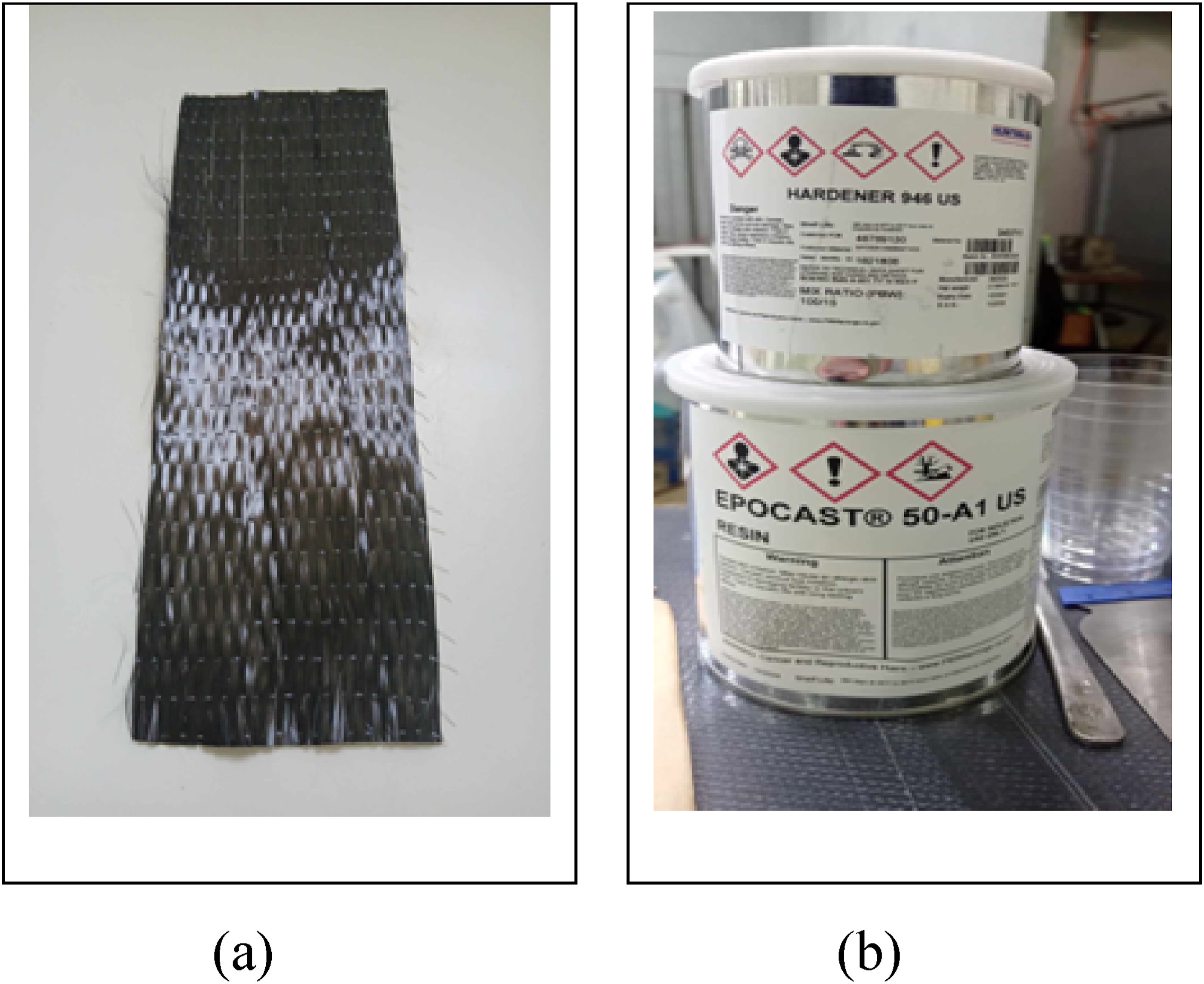
Mechanical properties of the Epocast 50-A1/Huntsman hardener 946. 30

Mechanical properties of the IM2-12K fibres. 31

Elaboration
The experience campaign was carried out on composite laminates fabricated by hand lay-out using a combination of Hexcel IM2-12K carbon fibre and Epocast 50-A1 epoxy.
According to Khashaba et al.,
30
the epoxy resin was mixed with Huntsman hardener 946 at a weight ratio of 15 % to ensure optimum curing behaviour and integrity of the matrix. The IM2-12K carbon fibres, with an average areal weight of 193 g /m2, were first placed on a thin plastic film and resin mixture was then applied evenly to the fibre sheets with a putty blade, as shown in Figure 2. Impregnation of the reinforcement.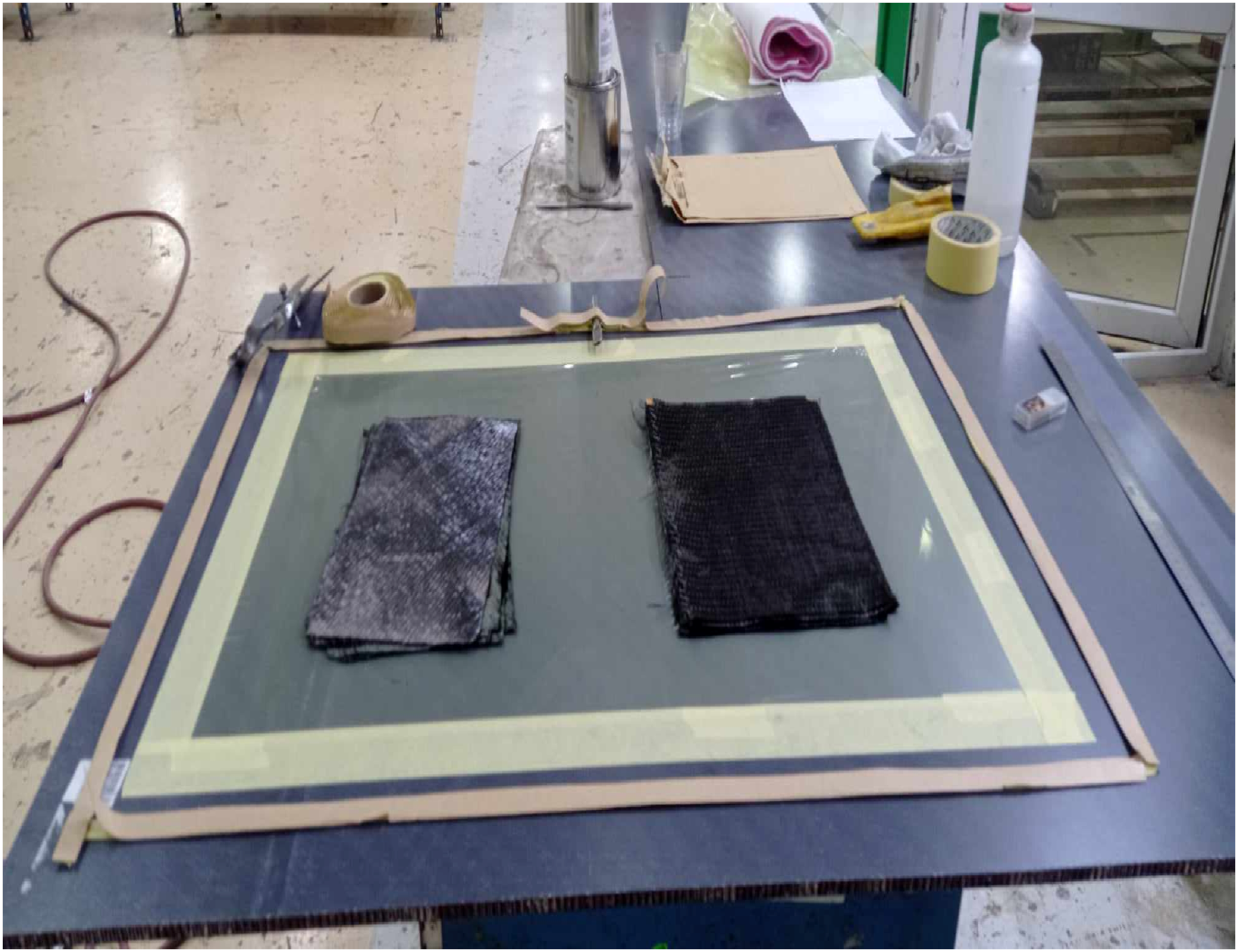
Layering was repeated to achieve the target stacking sequence and laminate thickness of 2 mm. A vacuum pump was employed during lay-up to remove entrapped air and excess resin, ensuring fibre wet-out and laminate uniformity.
Summary of test types and properties measured.

Specimens of the off-axis tensile testing were prepared with a symmetric stacking sequence of [(+45°/−45°)5]S. During the lay-up process, particular attention was set on ensuring uniform fibre orientation—aligning the odd-numbered plies at +45° and the even-numbered plies at −45°. The same processes were adopted for manufacturing compression and shear specimens. The lay-up of all fabricated laminates is summarized in Table 3.
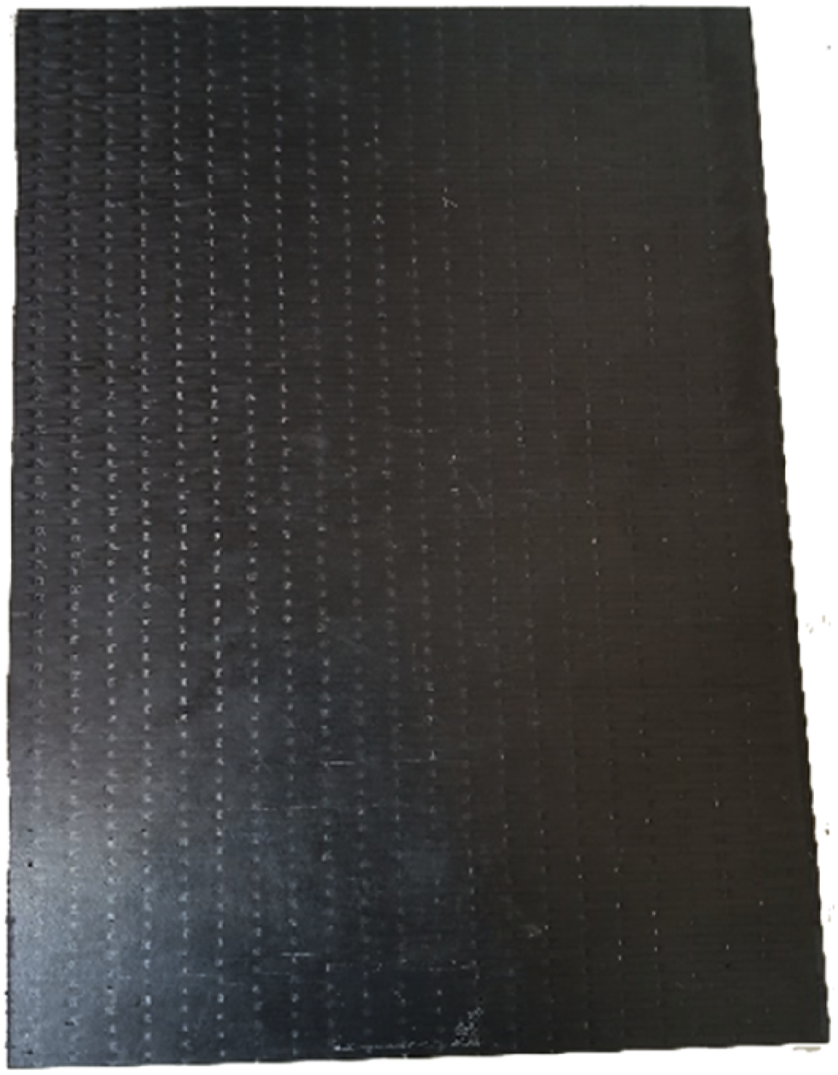
The entire hand-laying process and the fully cured laminate are illustrated in Figures 3 and 4, respectively. Vacuum molding process. Laminated carbon fibre/epoxy plates.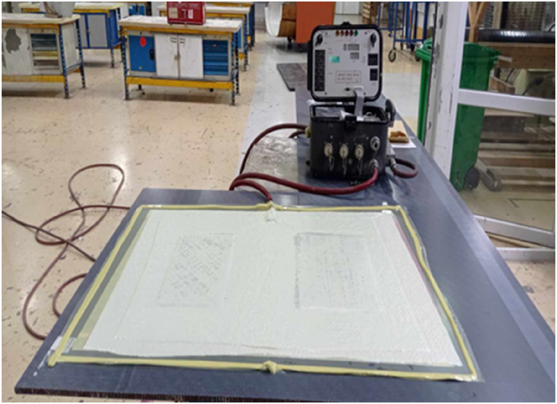
After curing process in controlled conditions, the obtained laminates were cut into normalized samples utilizing (see Figure 5(a)) a water jet cutter (Proto Max LFM-L-5 KN) at an operating velocity of 2.54 mm/min. To facilitate mechanical testing, tabs were bonded to both ends of the specimens to reduce stress concentrations at the grips and enhance load transfer (see Figure 5(b)). These tabs were fabricated from metal, conforming to relevant testing standards, and allowed for increased surface roughness at the gripping interface to minimize slippage and prevent premature failure. Tensile test specimen’s preparation (a) Cutting apparatus, (b) specimens.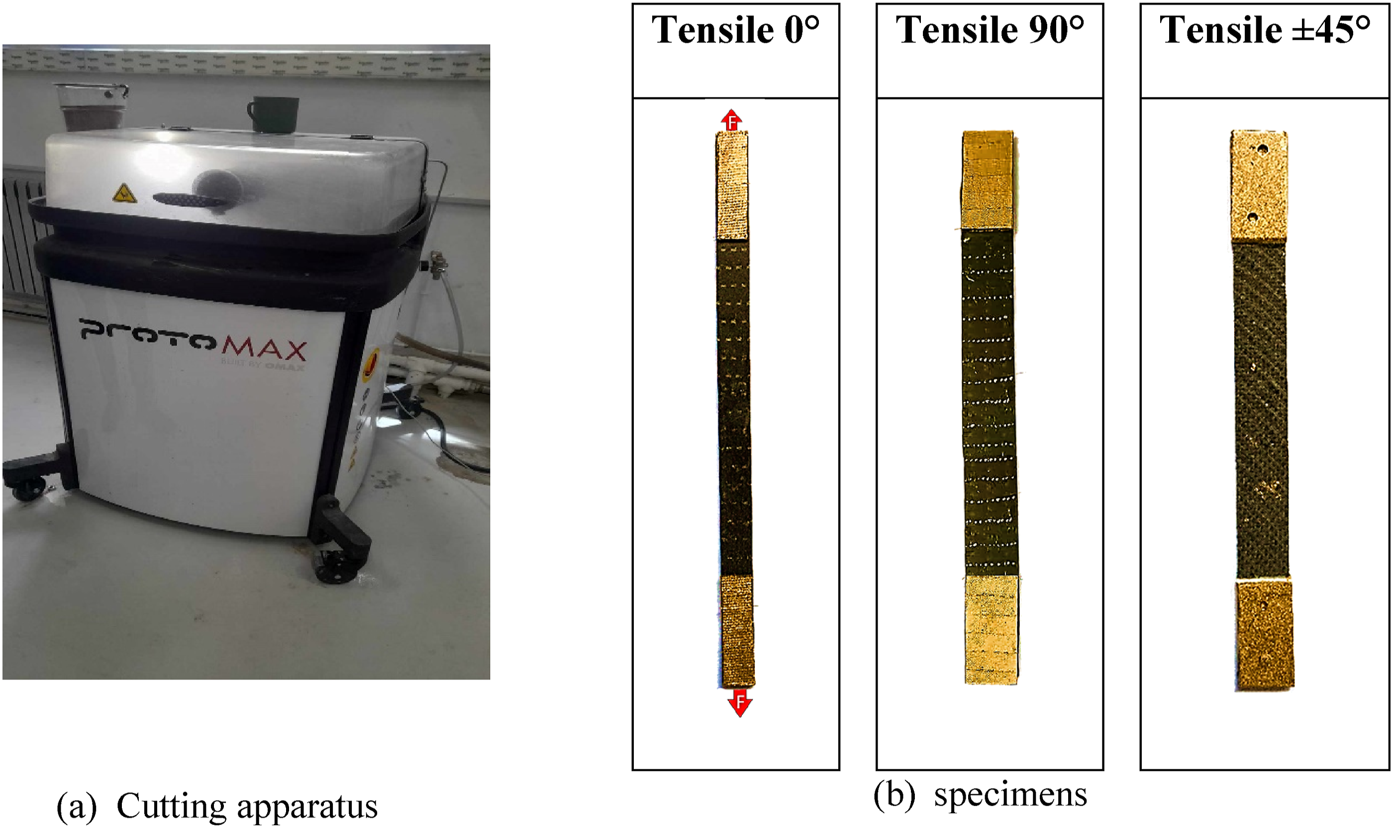
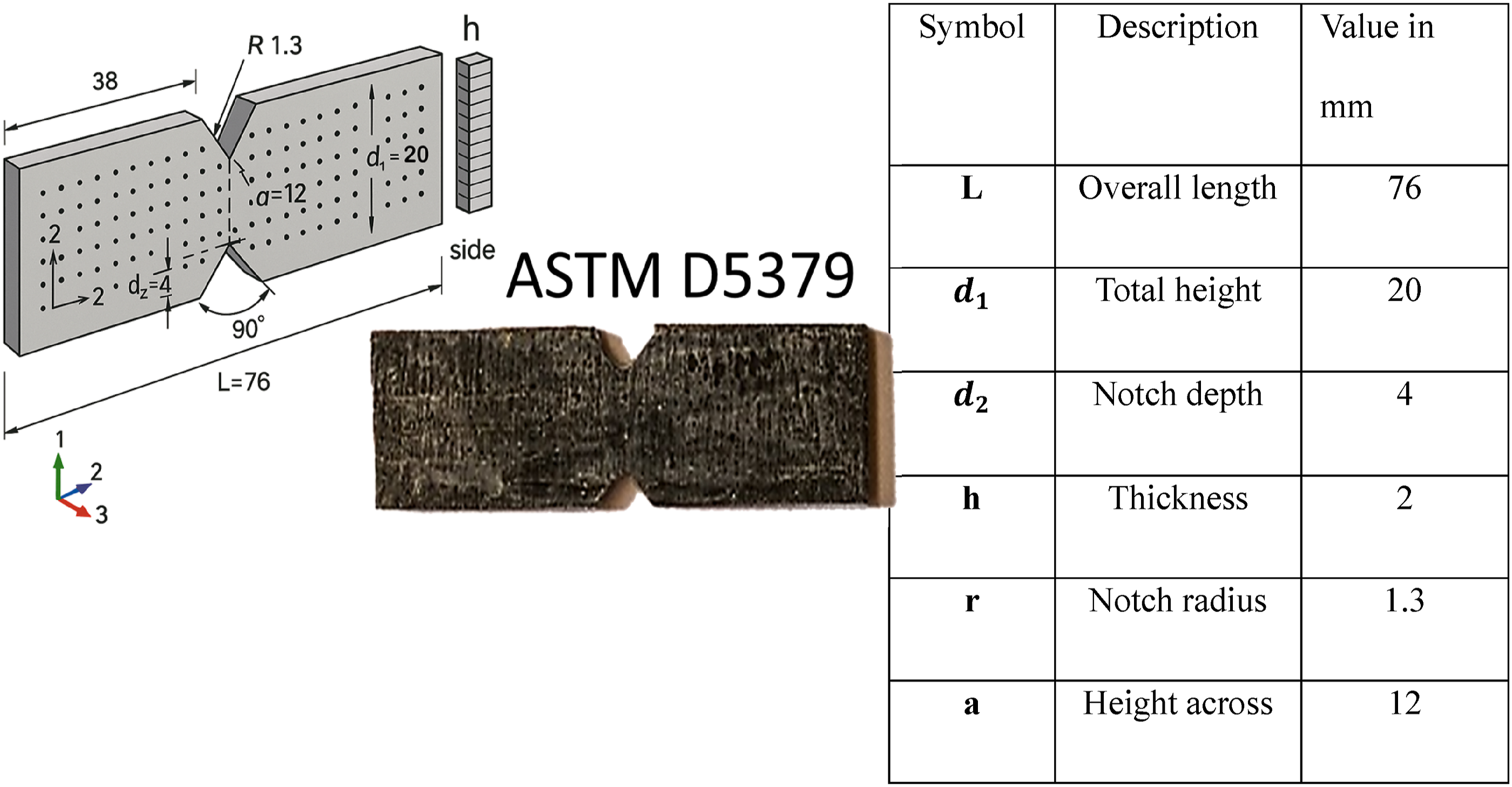
Additionally, for shear test characterization the specimens were prepared according to ASTM standard D5379.
32
The specimens were cut using a water jet cutter from a 20 mm-thick Hexcel IM2/Epocast 50-A1 laminate consisting of 90 layers. Each specimen was machined to a thickness of 2 mm. The specimens’ dimensions are illustrated in Figure 6, where the fibres are oriented in the transverse direction of the specimen. Path of the shear specimens, ASTM D5379.
32
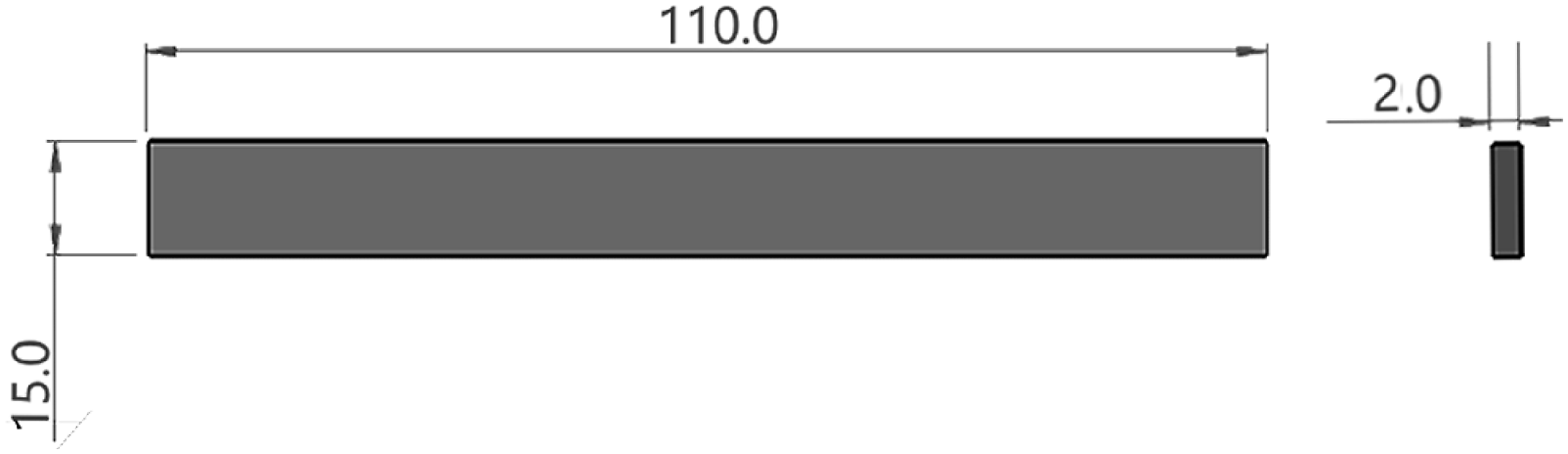
Finally, the flexural specimens was fabricated using the stacking Flexural specimens, ASTM D970.
33
Experimental procedure
This section discusses the detailed procedures for determining composite orthotropic properties.
Determination of constituent volume and weight fractions
In addition to the mechanical characterization experiments, the IM2-12K/Epocast 50-A1composite density was measured for the purpose of developing volume-based properties and more accurate definition of material model inputs.
In order to determine the percentage by weight of carbon fibres in the IM2-12K/Epocast 50-A1 composites, the ashing technique is applied in accordance with standard NF T 57-571.
35
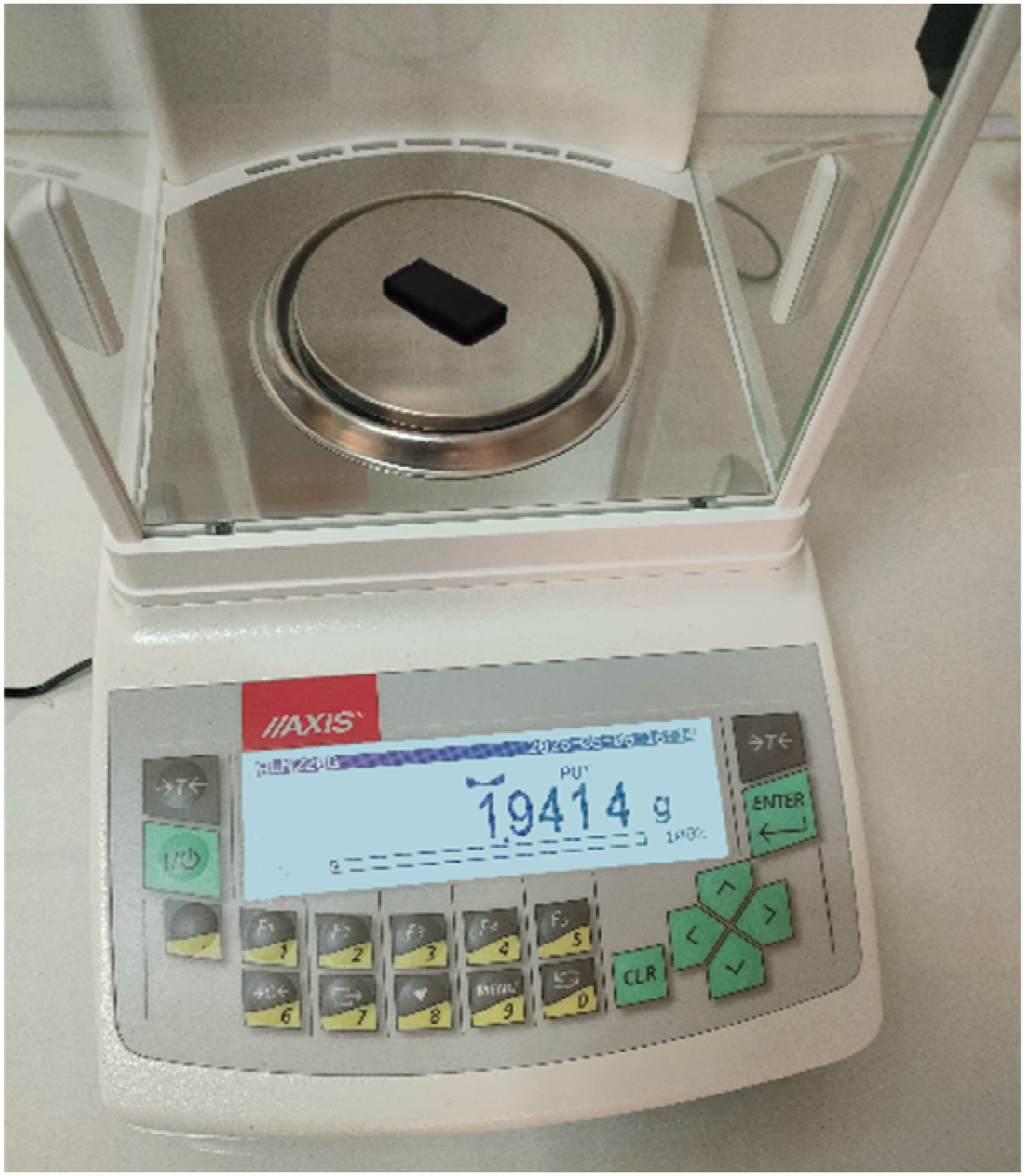
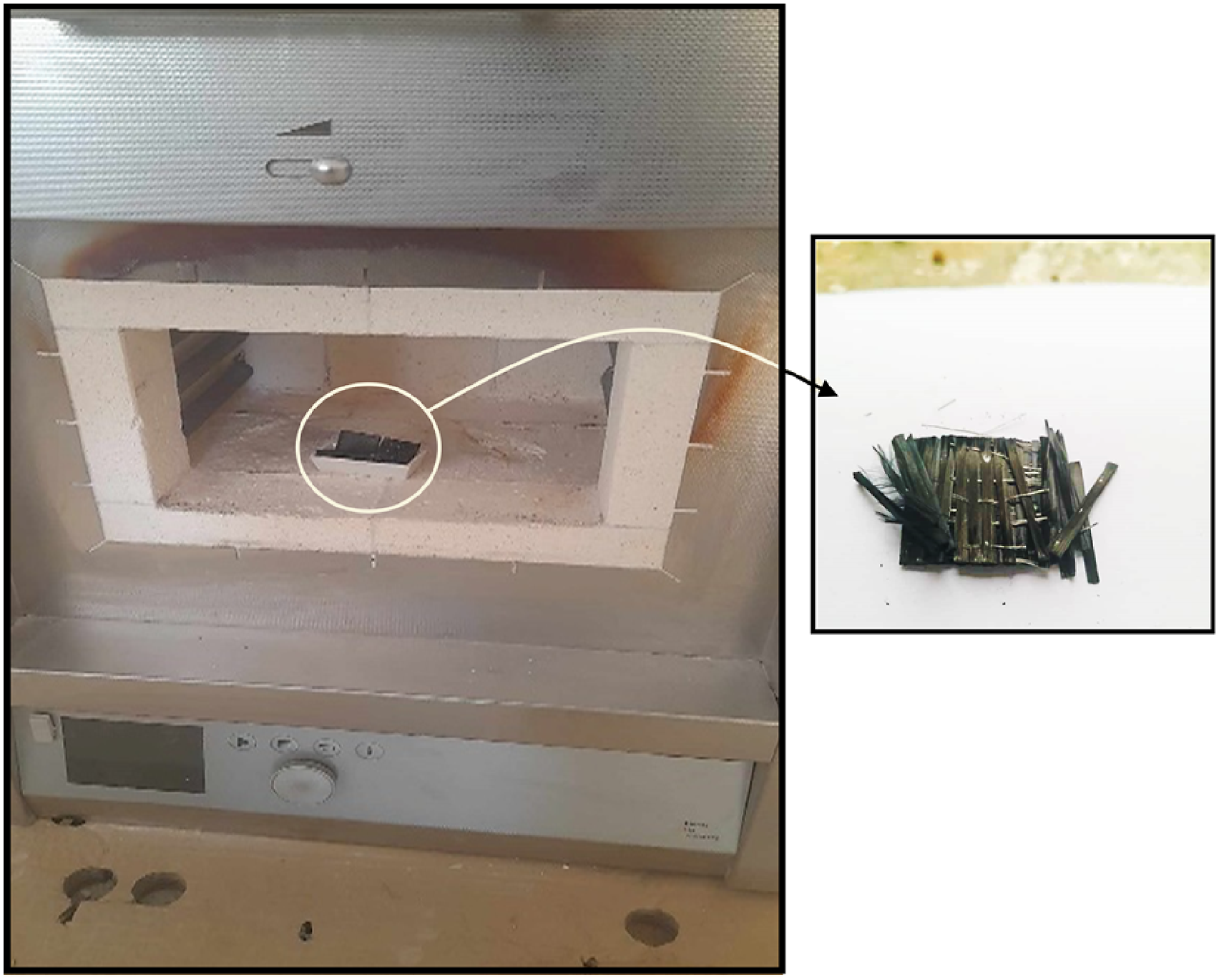
Two samples with a cross-sectional area of (1 × 1) cm2 are taken from the test specimens. Initially, each sample is weighed on a balance with an accuracy of ±0.0001 g, as shown in Figure 8, followed by placing it in a pre-weighed crucible. Subsequently, the crucible is heated in an oven at 600°C for approximately 2 hours, as shown in Figure 9, until the resin is completely burned off. The crucible is then placed in a desiccator to cool to a temperature at which no further weight change occurs. Finally, the crucible is reweighed with any residual ash, and the composite density is calculated in accordance with the standard NF T 51-561
36
using the following equation: Specimen weight measurement. Positioning ceramic crucible in Muffle Furnace. Characteristic of Hexel IM2/Epocast 50-A1 CFRP laminates using Ashing technique.



Tensile tests
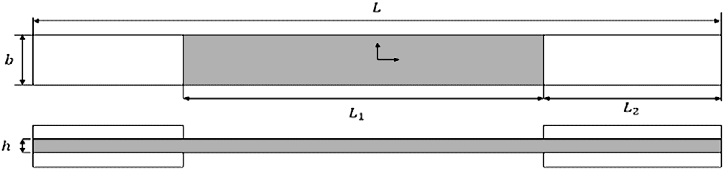
The tensile properties were assessed using an Ibertest universal testing machine equipped with a load cell of 100 kN capacity and Epsilon 3442 extensometer, as depicted in Figure 10. The specimen samples under consideration are those presented in Figure 5. The geometry of the tensile specimens was designed in accordance with reference 37. The design and dimensions of the specimens for the tensile test are detailed in Figure 11 and Table 5. The relevant standards for each tensile test are enumerated in Table 6. Experimental setup with optical measurement system. Geometry of specimens in mm, adopted from Ref. 23. Specimen dimensions. Summary of test types and properties measured.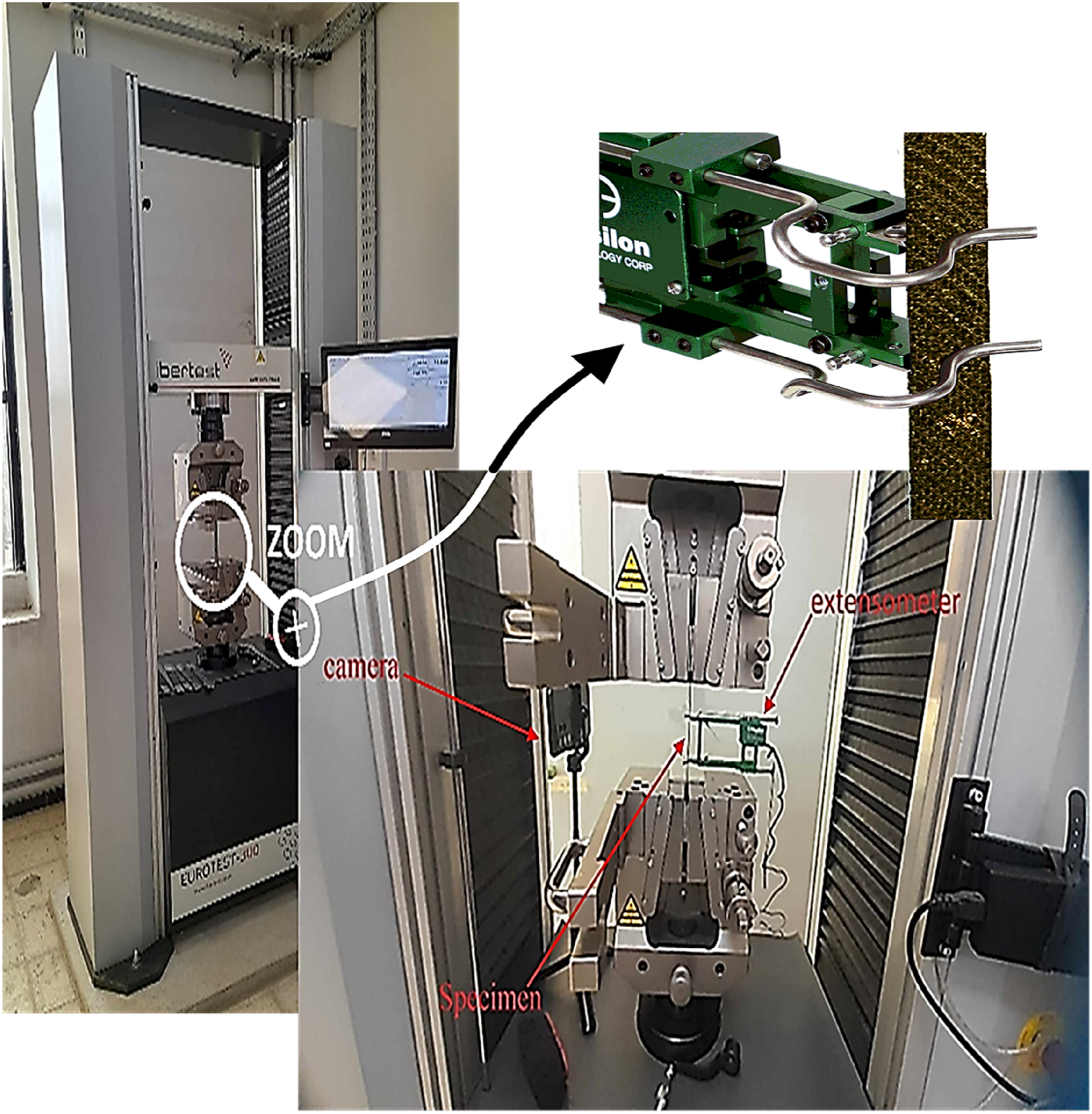


In this table,
The tests were conducted at ambient room temperature. To comply to standard strain rate protocols, a constant crosshead loading rate was set at 2 mm/min (0.034 mm/s), ensuring that rupture occurred within 0.5 to 5 min. Wedge-type constant position grips were used to maintain uniform clamping during tests. The loading rate was set at 2 mm/min (0.034 mm/s), and the tests were conducted at ambient room temperature.
Tension on (0°)10 and (90°)10 specimens
Through the tensile tests applied to three 0° specimens, the values for Tensile test for longitudinal stress measurements.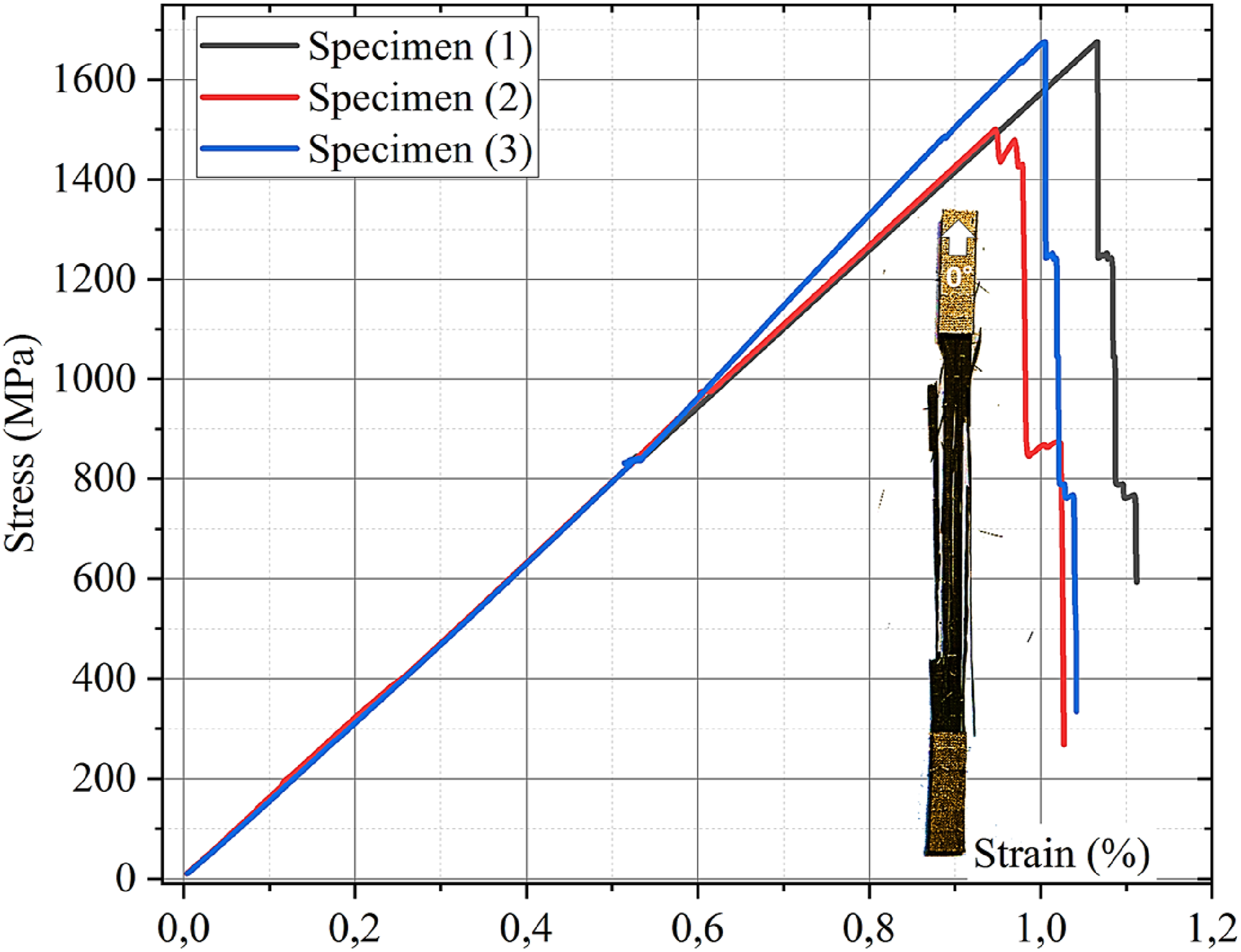
All specimen (1), (2), and (3) demonstrate an initial linear elastic area with analogous slopes, signifying equivalent stiffness. This indicates that the elastic modulus
The slope of the initial linear segment of the stress-strain curve offers a direct estimation of 
The range of Δε1 strains chosen for this calculation is ranged from 0.001 to 0.8%, which ensures that non-linear or damaged behaviour is avoided and that representative stiffness of the composite in its undamaged state is captured. Based on this method, the calculated value of the longitudinal Young modulus is:
To determine the Young’s modulus Tensile test for transversal stress measurements.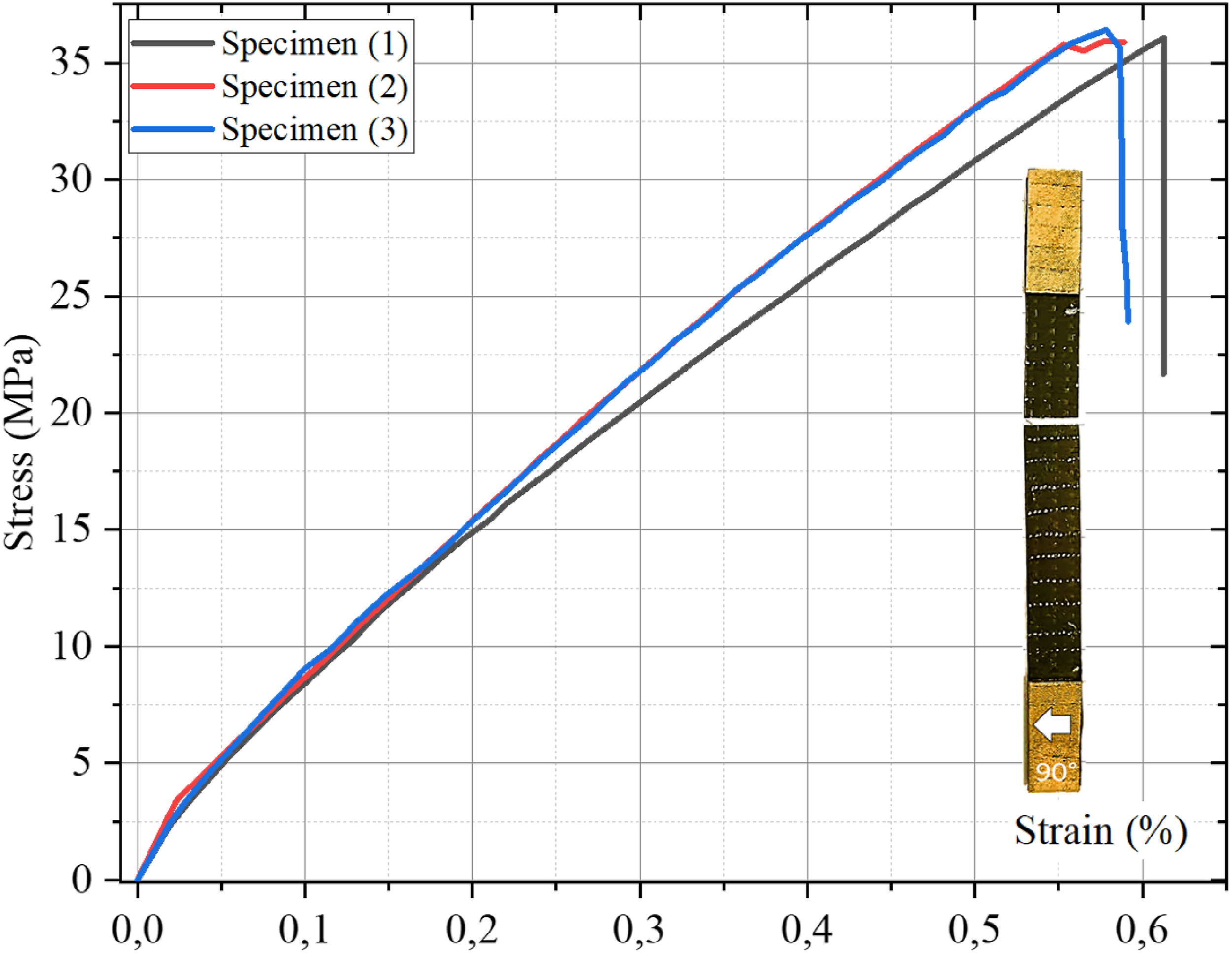
The stress–strain response demonstrates behaviour similar to that of the 0° tensile specimens, featuring an initial linear elastic phase succeeded by a clear failure event. The fracture mechanism in the 90° direction radically differs given that to the matrix-dominated force route. A brittle failure mode is observed indicating the markedly reduced strength and stiffness of the matrix phase relative to the reinforcing fibres, emphasizing the essential importance of matrix toughness and fibre-matrix adhesion in withstanding transverse tensile loads. The maximum stress values fluctuate between 35.60 and 36.06 MPa
For Young’s modulus 
The calculated value from the stress-strain curves is
To facilitate and expedite the comparison of deformation characteristics among specimens, Poisson’s ratio ( Image correlation for the Poisson’s ratio calculation. (a) In-plane Poisson’s ratio 
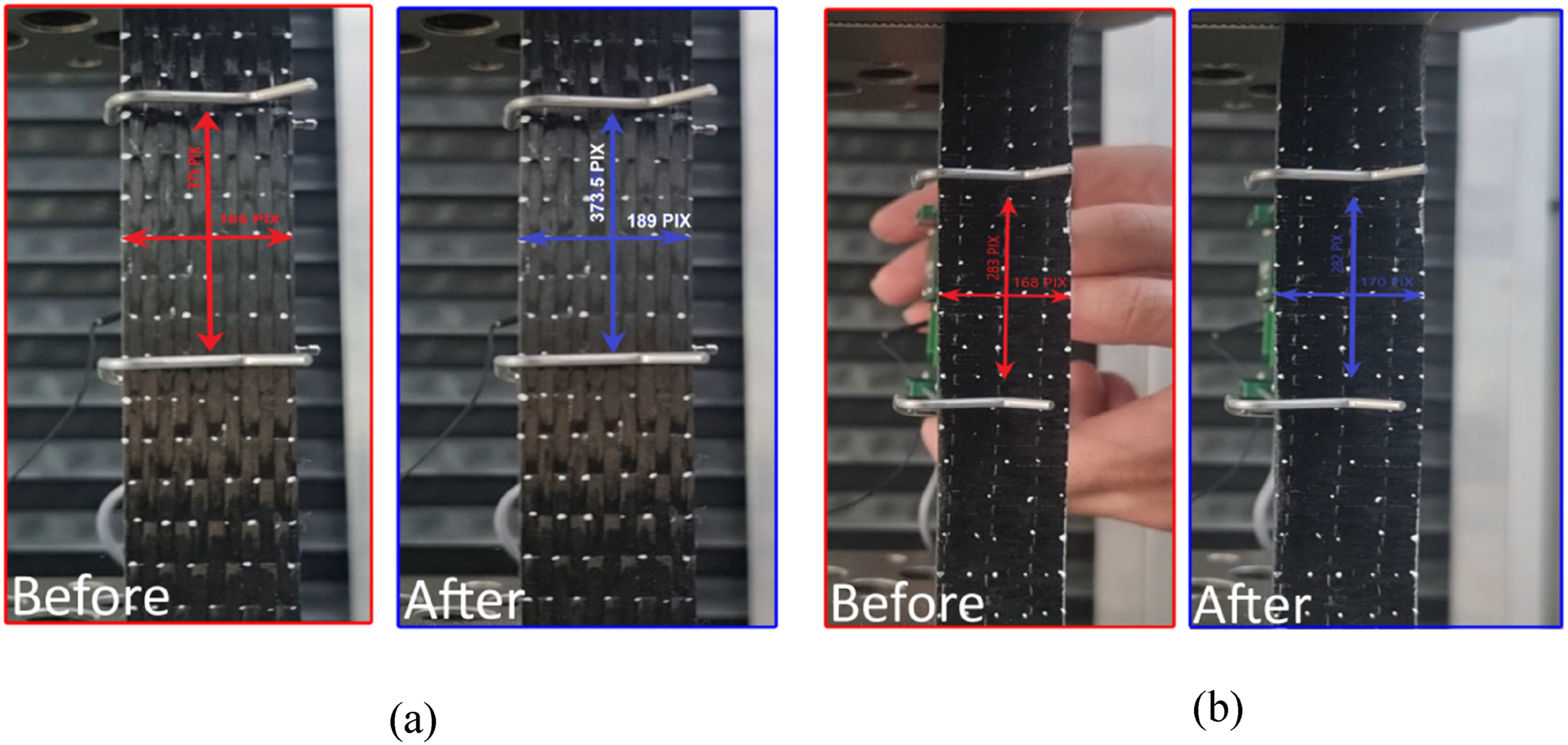
The calculated value of Poisson’s ratios
Tension on (+45\-45)10 specimens
The stress-strain response for Tensile results for specimens orientated ±45.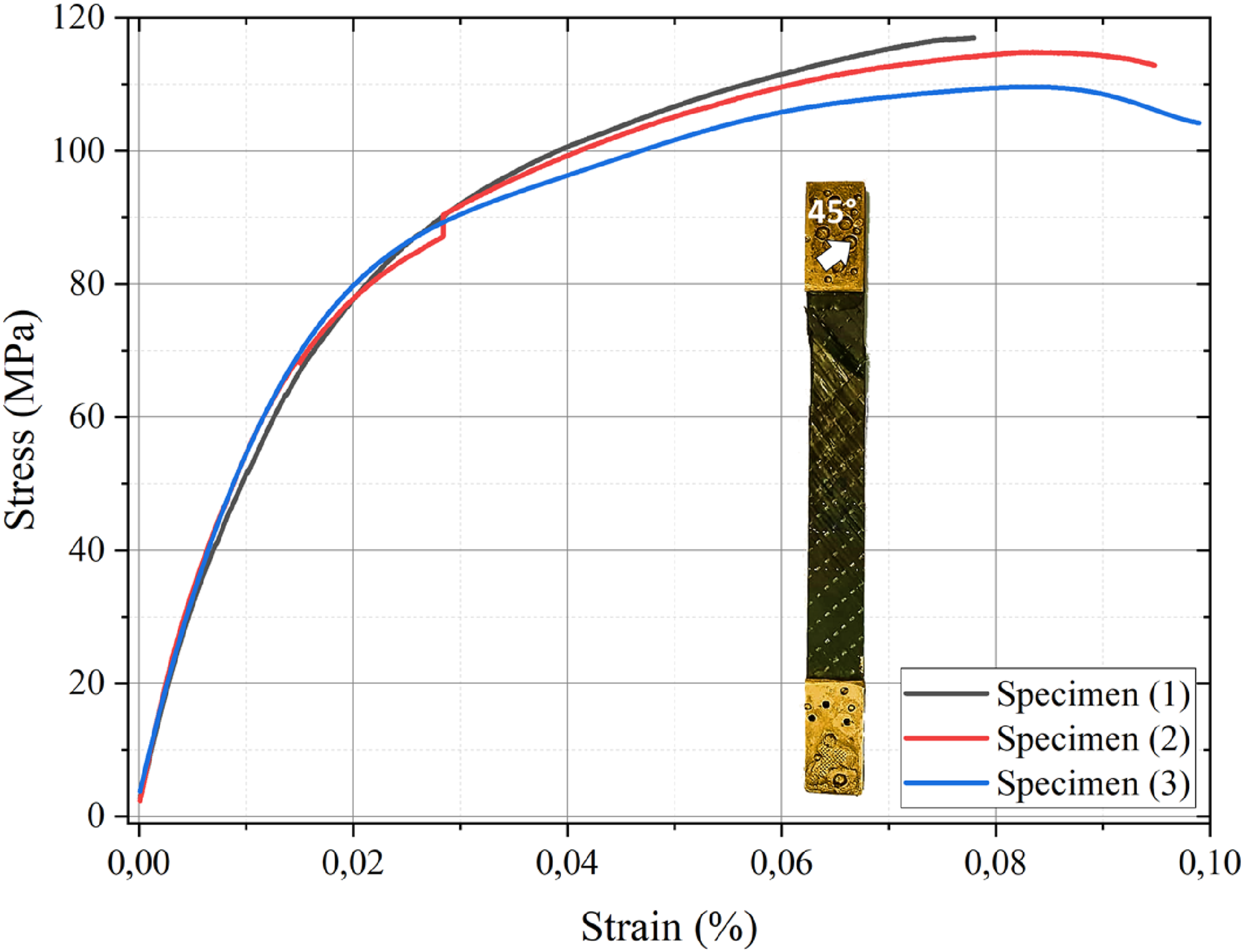
Significant in-plane shear data.

To extract the in-plane shear modulus of 


The evaluated value is
Tensile failure modes
The tensile failure modes are shown in Figure 16 for the all-tensile tests’ specimens. Damage outcomes for: (A) 0° fibre-oriented specimen, (B) 90° fibre-oriented specimen, and (C) ±45° fibre-oriented specimen.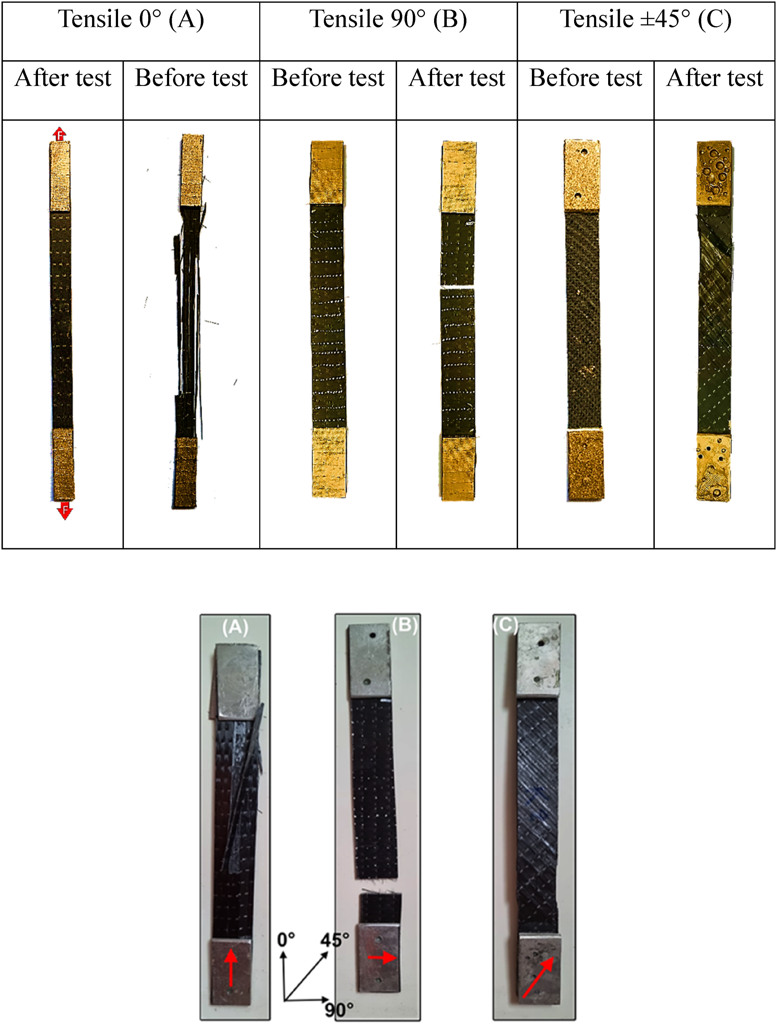
Barely visible damage (BVD) interpretation.

Compression test
Experimental compression tests were carried out to determine the values of Geometry of specimens. Dimension of specimen in compression.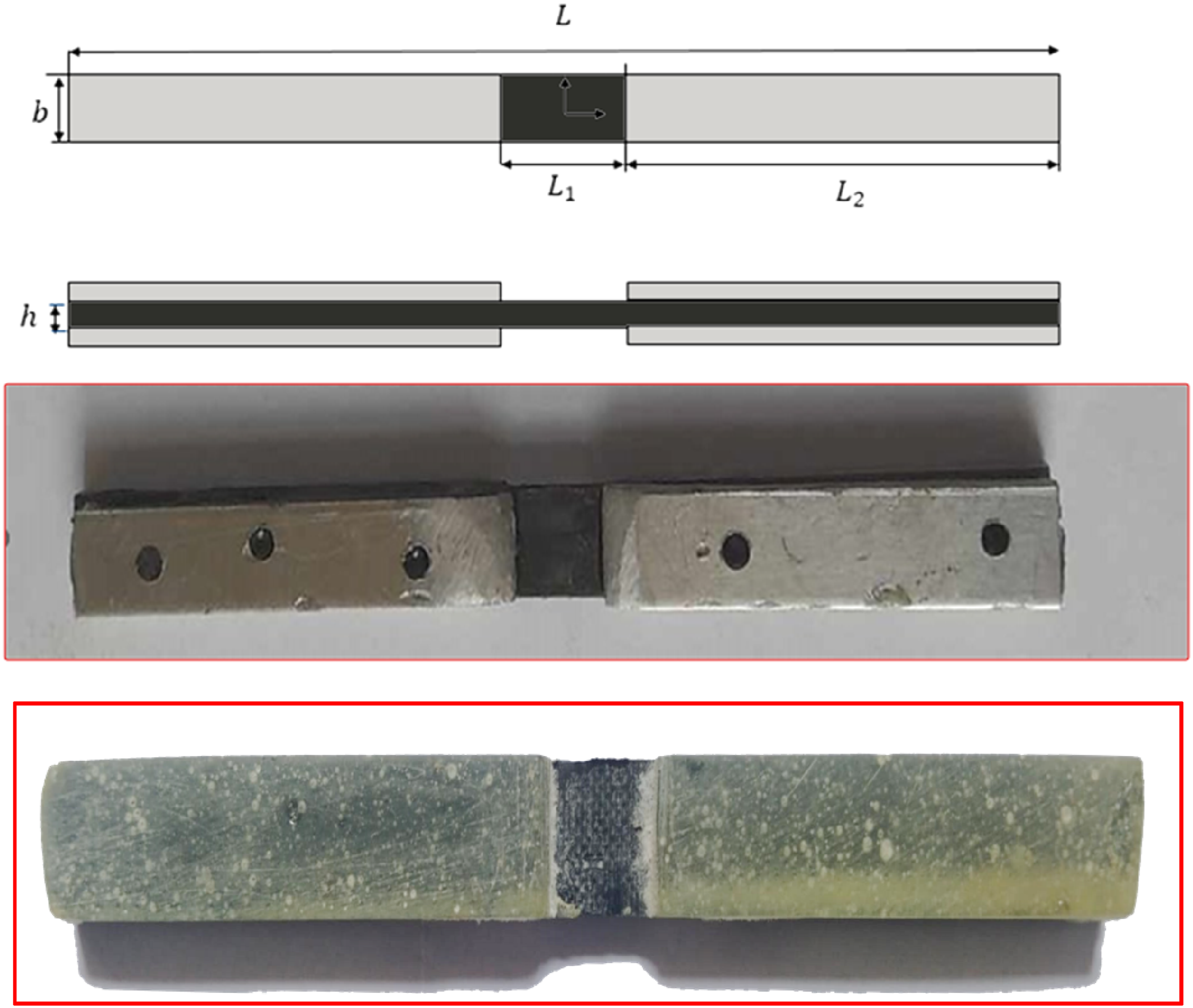

The compressive stress-strain curves for the three experimented specimens for the two orientations are depicted in Figure 18. The data used by Compressive stress–strain outcomes. (a) 0° specimens (b) 90° specimens.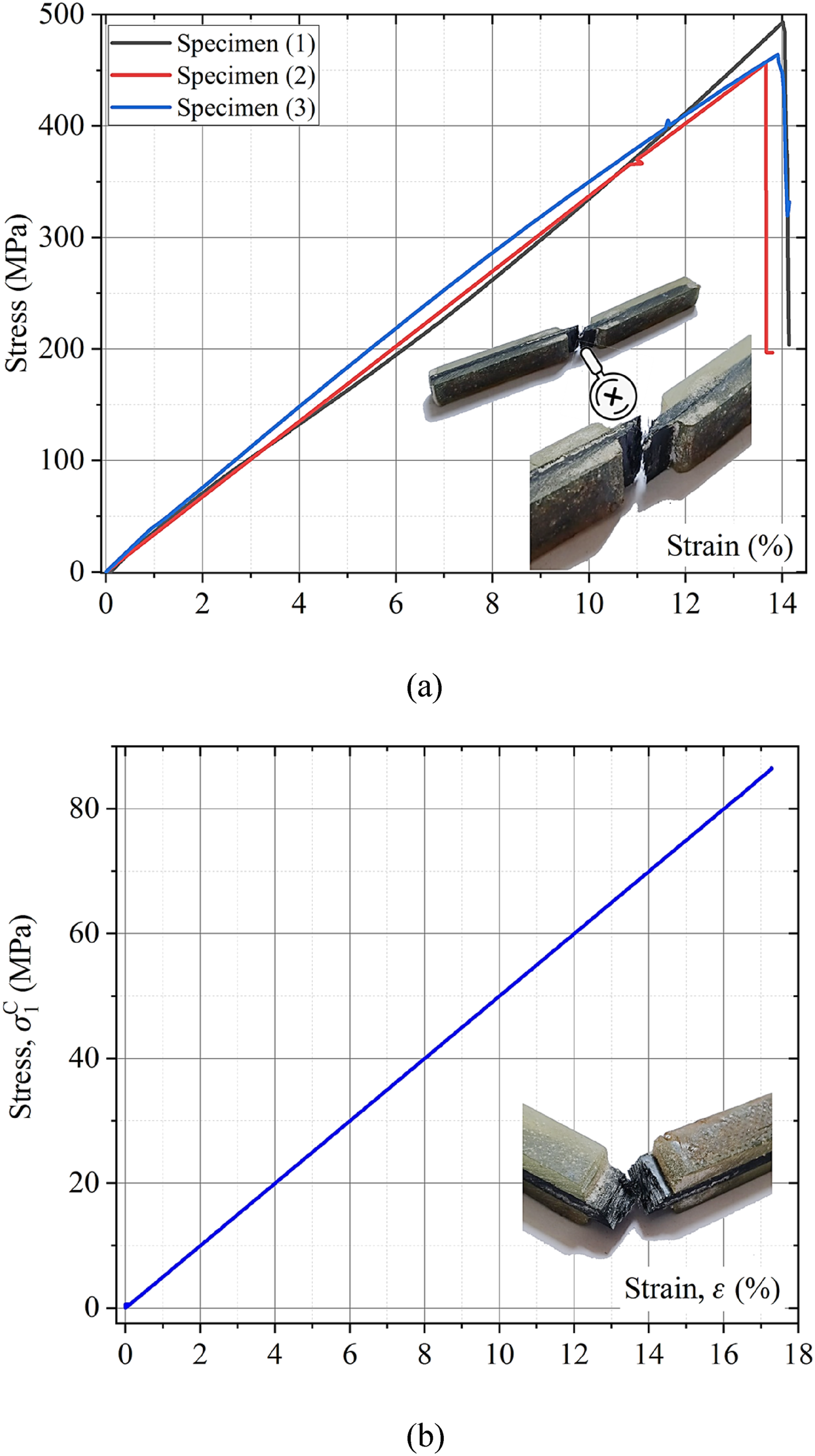
Shear test
This test is carried out to obtain an effective measurement of the out of plane shear properties for the sectioned composites. The load applied to the specimen during the shear test is illustrated in Figure 19.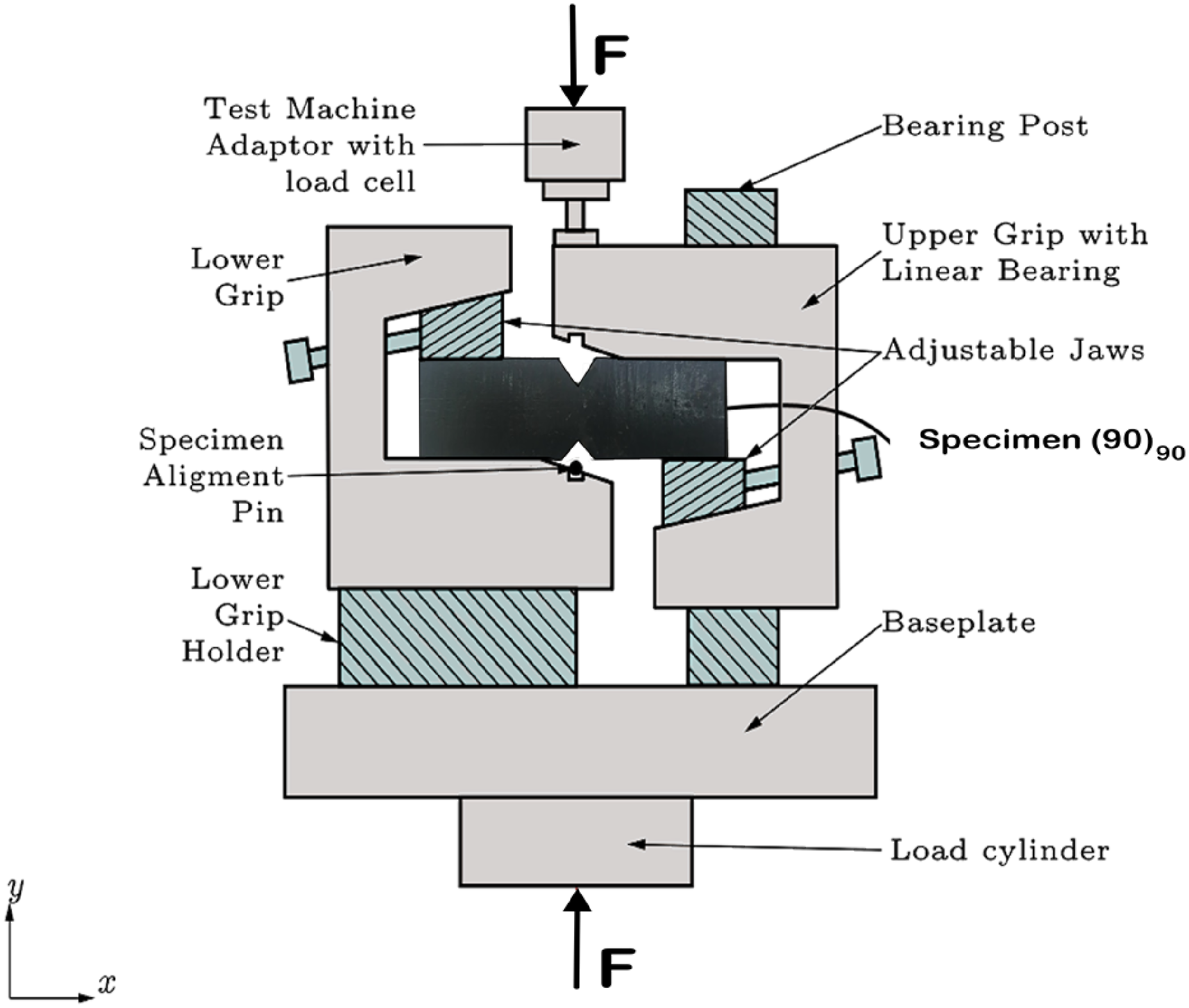
The outcome of the shear test is shown in Figure 20, depicting the curve of out of plane shear stress Shear stress versus shear strain.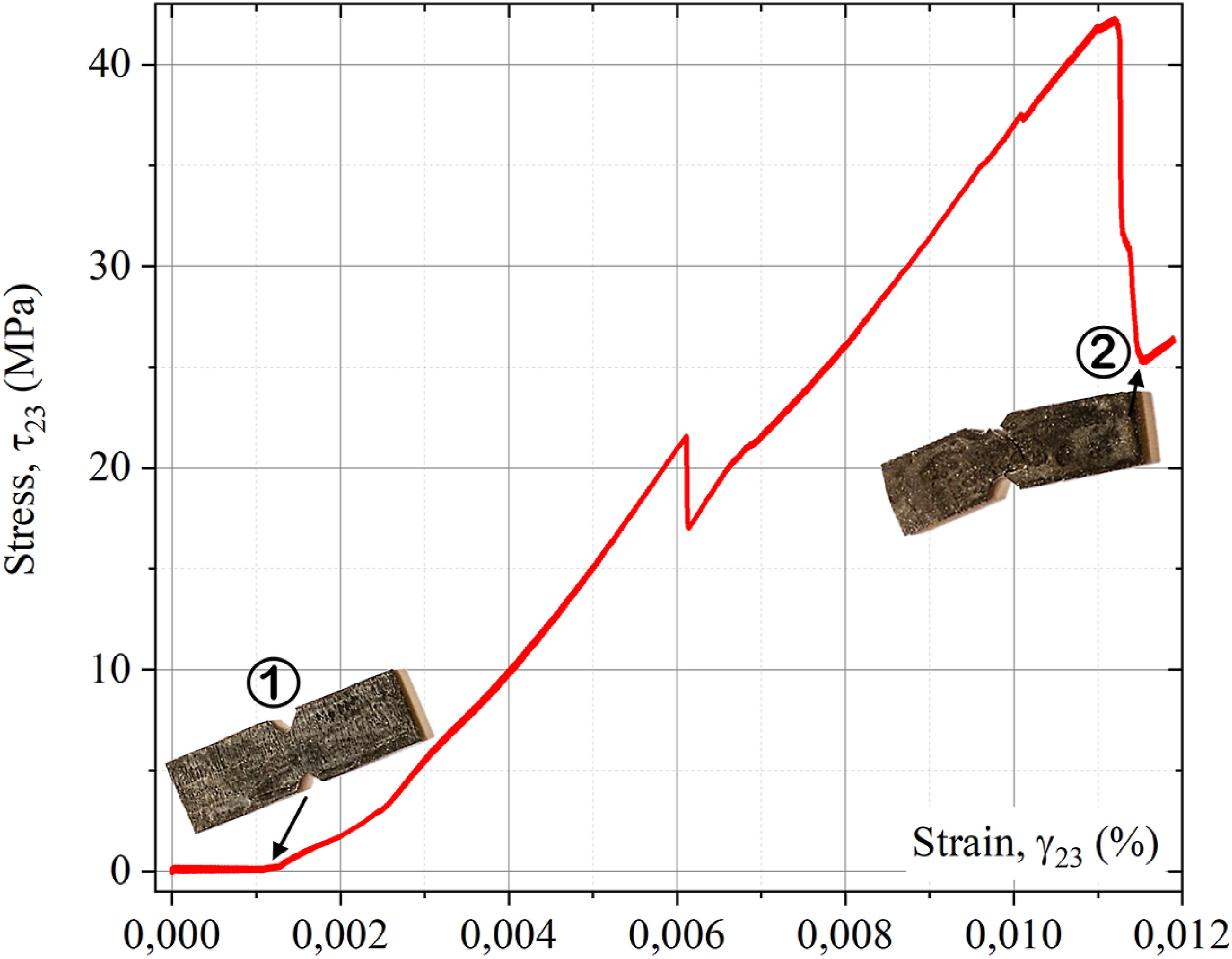
During the test, a further damages observations are made. Figure 21 indicates the shear failure mode that was obtained from the shear test. It is evident that the failure propagated from the V-notch towards the surface of the notch, making a 45° angle relative to the notch as it trailed to the vertical. Failure mode during shear test.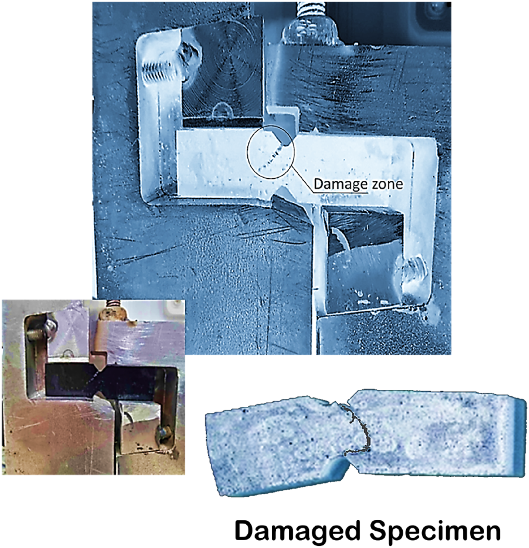
Summary of properties obtained.

Flexural test
In this test, the flexural strength Sample under deflection.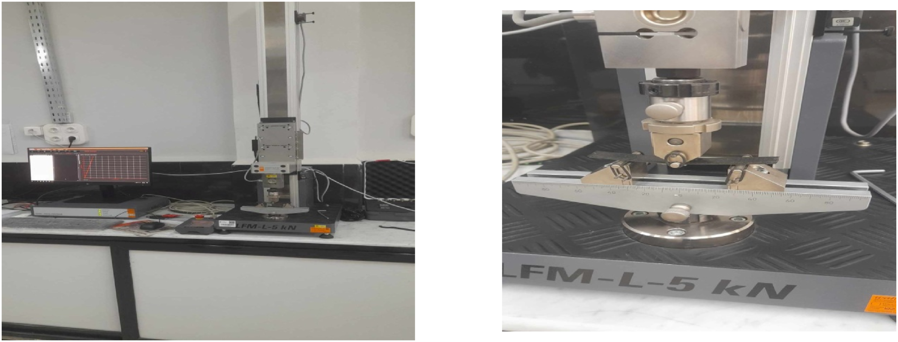
The force-deflection response as the stress-deflection during bending test are depicted in Figure 23. The flexural behaviour of the composite specimen tested shows an initial linear part, revealing the elastic behaviour, up to a deflection of about 3.7 mm. As deflection continues, the flexural response curves start to deviate from their linear path, revealing the onset of plastic deformation processes either in the matrix or at the interface of the fibres. Flexural forces versus deflection of the 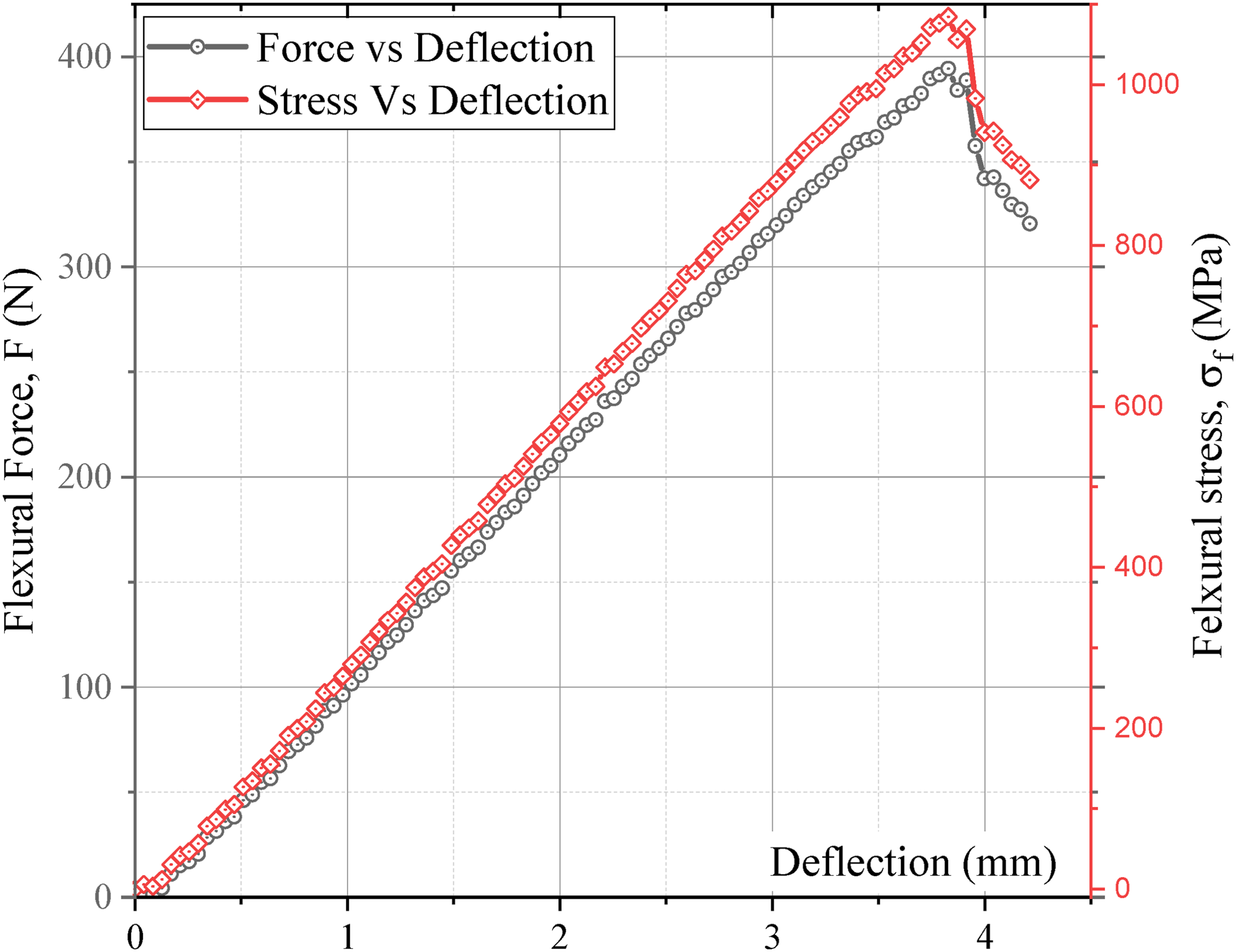
The maximum bending force applied in this case is close to Fmax = 400 N, which corresponds to a maximum flexural strength of
The standard formula 
Substituting our specimen values into equation (10) yields:
Validation cases
In this analysis, the tensile and flexural tests of the Hexel IM2/Epocast 50-A1 CFRP material was modelled using the commercial software package ABAQUS/Explicit. To this end, specimen was designed identical to the experimental works (see §2.2). To reproduce the experimental damage events Hashin damage was adopted to prevent it, using a VUMAT subroutine criterion.43–45 Needed modelling and criterion data are the imported from experimental data collected in Table 6 and then after incorporated into the model.
Tension modelling
The plate is modelled as a deformable solid element. The model loads and boundary conditions are shown in Figure 24. A displacement of 1.65 mm in order to emulate the experimental loading condition of 2 mm/min loading was assumed, for the top tab load and a fixity was attributed to the bottom support tab. The tabs were assigned a tied nodes coupling constrain with reference nodes using interaction module. Boundary conditions applied for the FE model.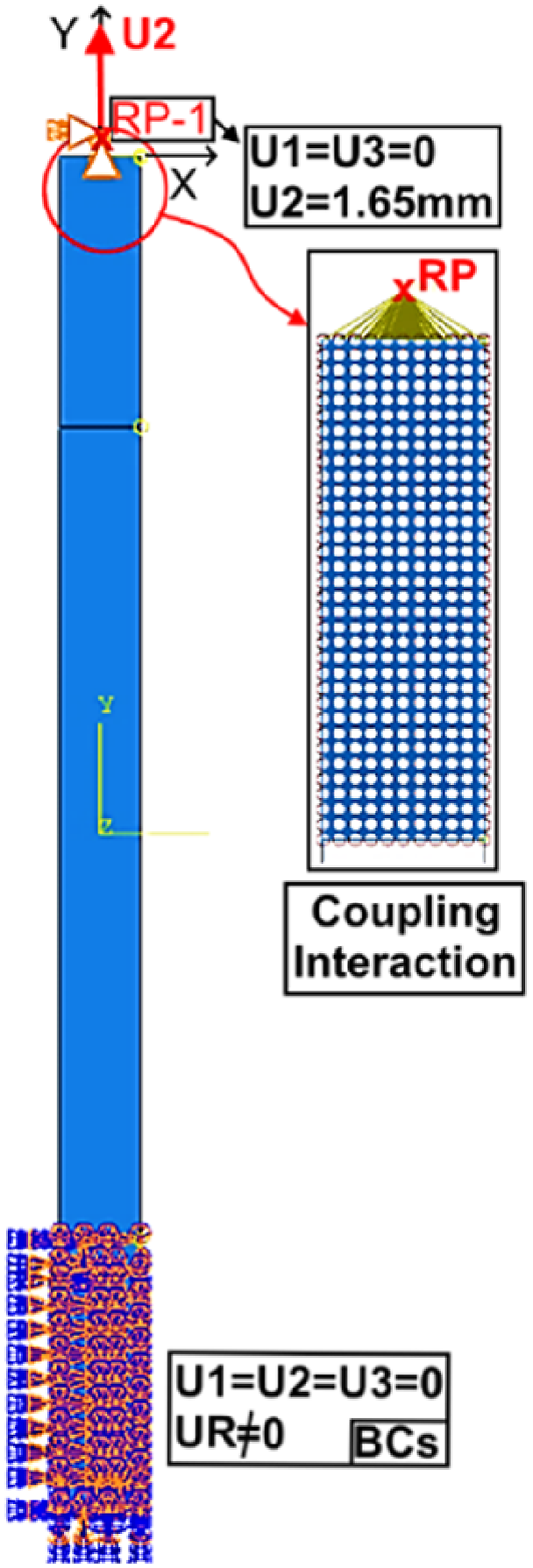
The composite plate was meshed using C3D8R elements with reduced integration, the hourglass control was enhanced. The mesh consisted of 8300 elements for the specimen, as shown in Figure 25. Meshed tensile model.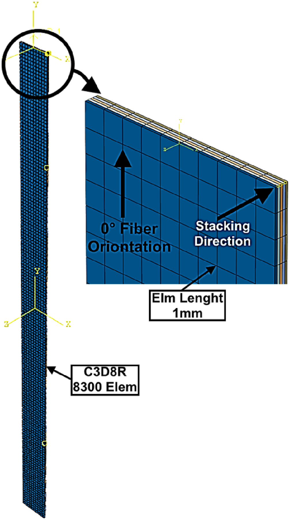
The numerical tensile response compared to the experimental results is depicted in Figure 26. Numerical response fitting versus experimental tensile results.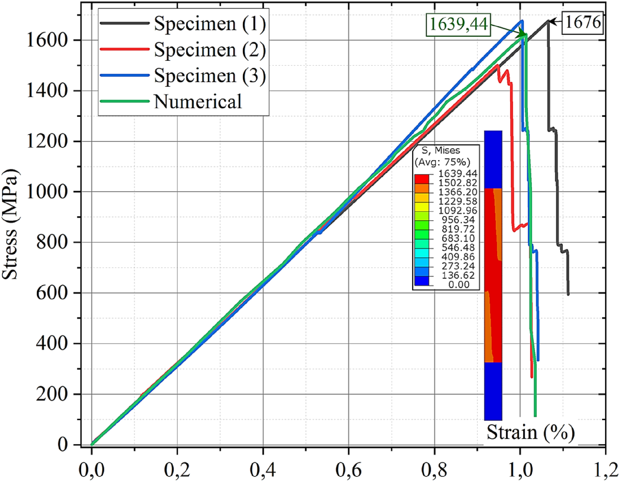
The numerical simulation demonstrates a linear elastic response until a strain of roughly 0.9%, attaining an ultimate stress of around 1639.44 MPa. This yields a calculated elastic modulus of about 150560 MPa, reflecting high stiffness found in the tensile experiments. Following that, the stress drops abruptly, indicating brittle failure in the simulated composite.
The numerical model aligns closely with experimental results in the elastic region, validating its predictive accuracy. The calculated error between experimental and numerical modelling for tensile test is 1.786% for elastic modulus and 2.18% for strength value. Additionally, the damages in the simulated specimen presented in Figure 27, show a high replication of the BVD during tensile test. Pointing the robustness of the VUMAT subroutine on showing how the damages propagates. The dominant damages were fibre traction presented on SDV3 and matrix cracking presented in SDV2. Ultimately, the numerical simulation gives more guarantee for the experimental inputted data, through this validation. Numerical damage from Hashin VUMAT simulation.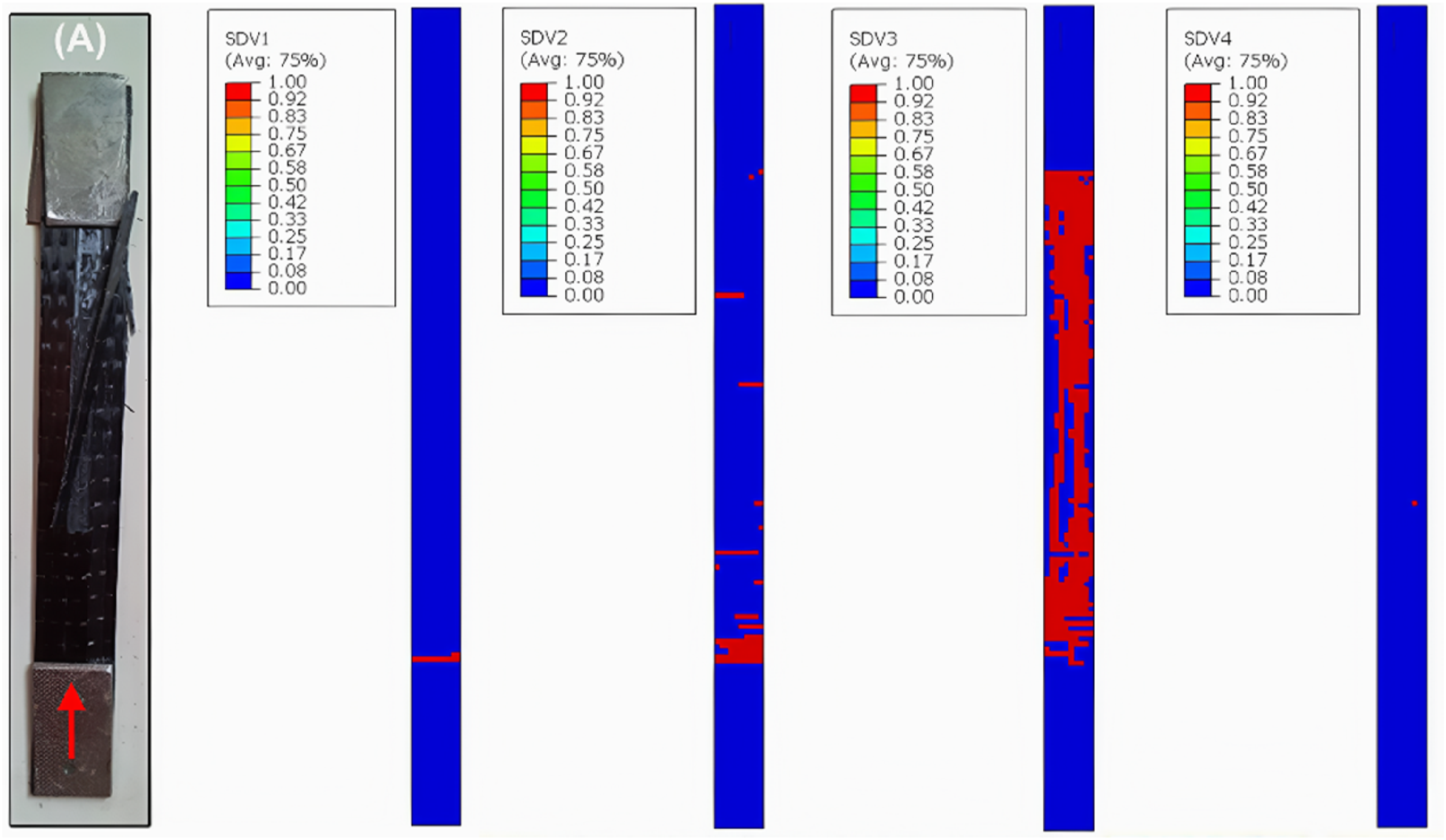
Bending modelling
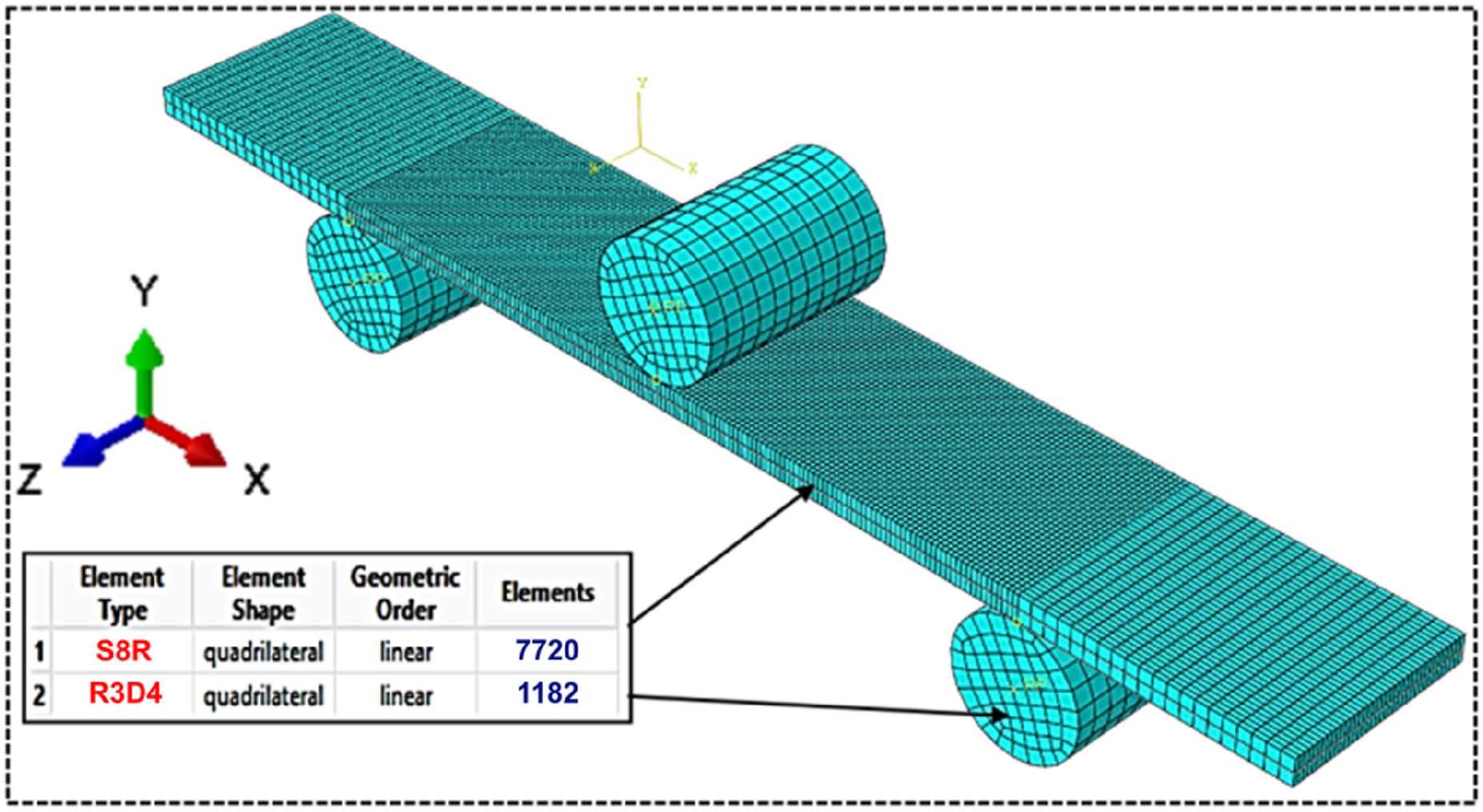
Another technic will be used trough this modelling without using the VUMAT subroutine, to show how the model converge accurately. The model was replicated in the same way for bending test specimen. In contrast to the tensile modelling here the plate was modelled as a deformable 3D continuum shell, and discrete rigid bodies are used for the pins that represent the 3-point support in flexural configuration. The model loads and boundary conditions are shown in Figure 28, assuming a velocity of 0.0334 mm/s in order to emulate the experimental loading condition of 2 mm/min loading, for the top pin load and fix of the bottom support pins. The plate was meshed using 7220, S8R shell elements with reduced integration, and a total of 1182 R3D4 rigid elements for the three pins the was used for the pins. Two elements partition were considered trough the thickness, as shown in Figure 29. Boundary conditions of the Bending model. Meshing for Bending model.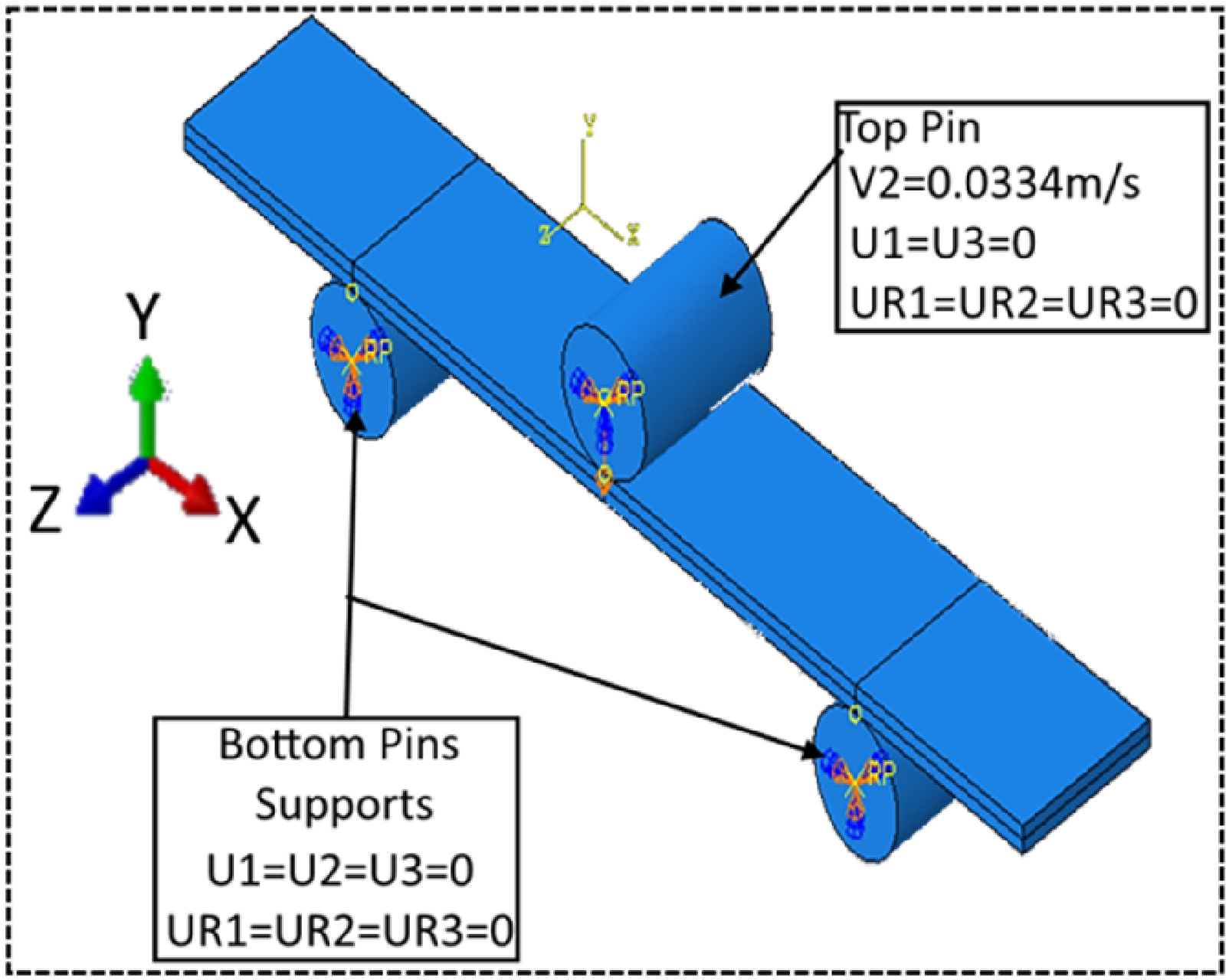
A comparative analysis of the force–deflection response obtained from numerical simulations and experimental testing is presented in Figure 30. The model provides a precise peak force and stiffness, validating the fidelity of the finite element framework and its constitutive parameters in the pre-failure regime. Maximum numerical bending force and stiffness reached approximately 455.8 N and bending modulus of 141280.1 MPa, beyond which a slight divergence between the numerical and experimental responses becomes evident. The registered errors are 1.77% and 0.14%, respectively, for flexural ultimate stress and bending modulus. Particularly, whereas the experimental curve displays a gradual load reduction indicative of progressive damage, the numerical model exhibits a more abrupt post-peak drop. 3D-Bending forces comparison numerical versus experimental.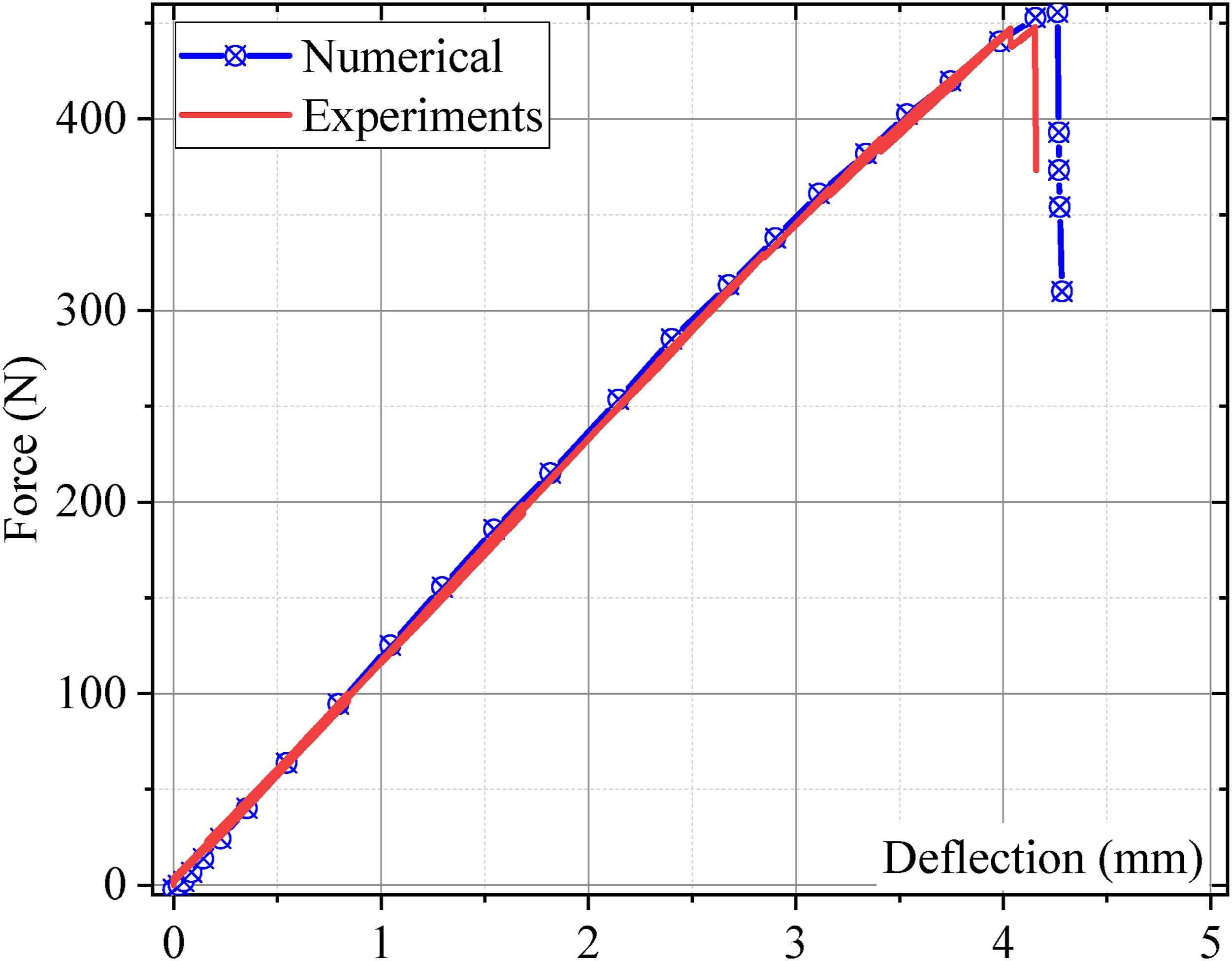
Finally, in order to provide greater insight into the Hashin criteria, additional data are presented in Figure 31, which illustrates that the predominant damage is registered for fibre and matrix under compression. The same observation as above were made for tensile predominant damages, underlining the constituent roles and also confirming the high accuracy of the inputted data. Hashin damage indicators for both fibre and matrix.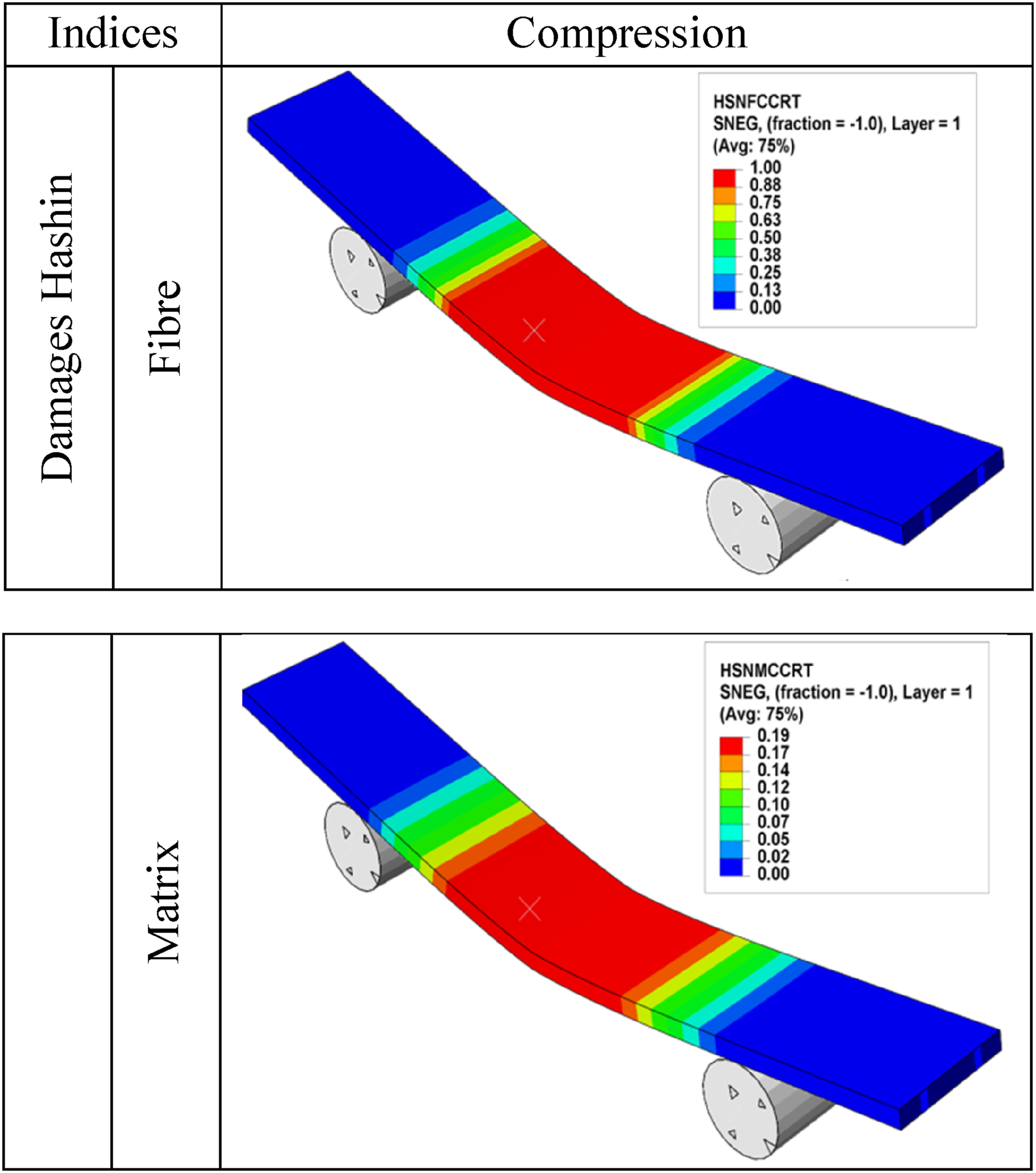
Conclusion
The study was conducted to study the mechanical behaviour of carbon fibre IM2 reinforced with resin Epocast 50-A1. The main conclusions about this study are as follows: - To identify the orthotropic behaviour, involving elastic and failure parameters, of the IM2-12K/Epocast 50-A1 laminate, a campaign of mechanical tests was performed. - The uniaxial tension and compression tests helped in identifying key elastic constants, including the Young’s modulus, the Poisson ratio and the ultimate tensile strength in both longitudinal and transverse directions. Complementary, shear tests were conducted, which allowed for the determination of the material’s in-plane shear modulus and shear strength, thereby offering a comprehensive mechanical description of its orthotropic response. - Essential information about the material’s flexural modulus, flexural strength, and damage initiation processes under out-of-plane loads was obtained through the use of three-point bending tests to assess the flexural behaviour. - The dominant failure modes in tension are matrix cracking initially, then delamination and decohesion, and ultimately fibre fracture. In compression, a matrix cracking appears initially, and then a dominant delamination phenomenon followed by a fibre kinking was observed. While in the shear loading, there is mainly a matrix cracking. - A modelling using the collected data was assessed, to validate their precision and showing the model accuracy. - The application to the FE simulation on tensile and three-point bending test, using the identified behaviour model, shows a good agreement in terms of stress-displacement and force-deflection responses, thus validating the identification procedure. - The Hashin criterion implemented in the VUMAT enables the damage assessment, and illustrate the same damage mechanisms occurring during tests. - This extensive dataset supports precise numerical simulation and constitutive modelling. Furthermore, the generated dataset provides valuable reference values that contribute to enriching the limited experimental data available on IM2-K12 fibre composites, especially under multiaxial loading conditions. - The mechanical characterization developed in this work will be integrated into future experimental and simulation frameworks with the aim of evaluating patch repair strategies and impact behaviour (both low- and high-velocity), where reliable input parameters are critical.
Footnotes
Author Note
Following are authors institutional email Address: Tarek Bouakba: t.bouakba@univ-batna2.dz, Khelifa Guerraiche: k.guerraiche@univ-batna2.dz, Djemaa Guerraiche:  .
.
ORCID iDs
Funding
The authors received no financial support for the research, authorship, and/or publication of this article.
Correction (September 2025):
The article has been updated with department name for the first author since its original publication.
Declaration of conflicting interests
The authors declared no potential conflicts of interest with respect to the research, authorship, and/or publication of this article.
Correction (November 2025):
In the published version of the article, the caption for Figure 2 was incorrectly given as “Stress-strain curve: (a) Aluminium 2024-T3 [12], (b) Adekit A-140 [12].” It has now been corrected to “Impregnation of the reinforcement.” The online version has been updated accordingly.
Data Availability Statement
Data sharing not applicable to this article as no datasets were generated or analyzed during the current study.