
Abstract
A variety of discontinuous fiber composite laminate layouts were designed to satisfy special structural needs. Corresponding composite tensile coupons having preset interleaving ply were tested to measure their strength and rigidity. The experimental results show the strength of the interleaving ply composite is significantly lower than that of the continuous one, whereas it has comparable rigidity. The internal load transferring mechanism was suggested to analyze the main factors affecting the ultimate tensile strength. Based on it, a statistical relationship has been built to reflect the dependence of the strength to the interleaving length.
Introduction
Continuous carbon fiber reinforced composite has been using in various fields, especially in aircraft structure manufacturing, owning excellent strength to weight ratio. The design of such composite structures primarily focuses on ply arrangement and the orientation of individual plies. While a vast number of layout patterns can yield a broad spectrum of mechanical properties, certain specific requirements remain challenging to fulfill with conventional continuous ply layouts. A particular requirement is that compulsory need of orientation change in an individual ply. For example, some unmanned aerial vehicle, whose left wing, central wing and right wing are designed as a whole part rather than an assembly of many parts and fasteners, would be more integrated, reliable and economical. One of the key challenges of this design is that the orientation of the fibers is difficult to change in the plane whereas this requirement should be meet due to symmetric sweep angles of the two wings. Figure 1 shows this configuration. Schematic illustrations of interleaving ply application.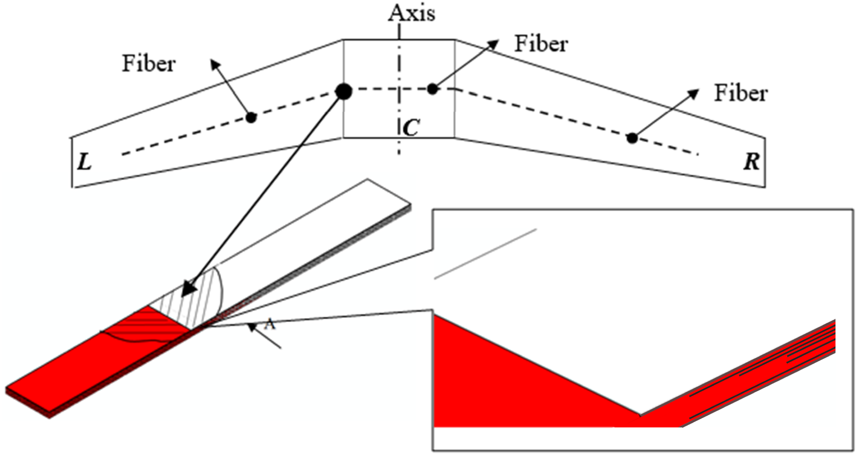
To address this challenge, this study proposes a novel layup design termed “interleaving ply” (see enlarged view in Figure 1). The core innovation of this approach lies in the introduction of intentionally designed discontinuities within individual layers. This strategy enables localized changes in fiber orientation within a single ply—a capability not achievable with conventional continuous fiber composites. The prepreg plies of two sides are laid separately to meet required orientations. In order to enhance the strength, the layout of multiple layers in the laminate is interlaced. Using this idea, the fiber orientation could change in an individual layer of the composite. However, this design may lose strength to certain extent compared to conventional continuous fiber ply. Meanwhile, various ply parameters could affect the properties of this kind of composite.
Numerous related researches, mainly about particular composite joints, patching repair, hybrid ply design and tapered laminates with ply-drop technique, have been carried out. These works could be divided into three parts.
The first part has relevance with interleaving ply technique directly. Ahamed 1 suggested a ply-interleaving technique to joint glass and carbon plies, which could be used in radar transparent window with reliable high strength. Jasim Ahamed et al. 2 presents a ply-interleaving technique for joining dissimilar composite materials. Based on this concept, they3,4 proposed a new, partially discontinuous design to improve the mechanical performance of pseudo-ductile, unidirectional (UD) interlayer carbon/glass hybrid composites and carbon fiber/epoxy composite respectively. Yu et al. 5 prepared and tested several highly aligned and well-dispersed short fiber hybrid composites with different carbon/glass ratios which were performed to investigate the effect of carbon ratio on the stress-strain curve. The influence of joint parameters on the performance of the stepped-lap joints have been investigated by series of linear FEM simulation cases without progressive damage included. 6 Jalalvand et al. 7 developed a new FE-based approach for modeling all possible damage modes in glass/carbon UD hybrid laminates in tensile loading, and the model used partially based on statistics and probability rather than explicit damage progressive models. Baucom et al. 8 fabricated tiled composite by tailoring every continuous prepreg into segments and evaluated the mechanical behavior. Camanho 9 proposed a new decohesion element placed between solid finite elements to model the delamination initiation and propagation and it was be used widely currently. Hashimoto 10 proposed a simple analytical model to predict the tensile strength of discontinuous fiber-reinforced composted with arbitrary fiber orientation angles. Aniello et al. 11 proposed the redesign of composite aeronauticals using double-double laminates by optimizing ply sequencing and orientations, significantly reducing structural weight while improving production efficiency and performance. Garofano et al. 12 evaluated the effectiveness of the double-double design on the crashworthiness of fuselage barrels, demonstrating a notable enhancement in impact resistance and structural energy absorption capacity.
The second part includes various bonded joints. When these joints undertake high stress, the shear stress distribution would determine the capability of the joints. How to assess the shear stress distribution would give helpful information in interleaving ply technique. Tsai and Morton used Moire 13 interferometry to measure the in-plane deformation of the overlap region, indicating shear stress distribution of the adhesive interface. Kim et al.,14,15 Seong et al., 16 Kweon et al. 17 conducted a serious of studies on adhesive bonded single-lap joints to investigate the effect of various parameters and processes. Harman and Wang 18 presented an analytical method to optimize the profile the scarf joint to make the interface stress uniform. In order to simulate the cohesive behavior between plies. Yoo et al. 19 analyzed the effect of scarf-patch bonding method under static and fatigue load condition and discussed the parameter influence on strength recovery rate. Avendano et al. 20 made experiments to compare the properties of single lap at room temperature and elevated temperature and use cohesive laws to simulate.
The third part is about effect of ply-drop in tapered composites. The ply-drop would be susceptible to interlaminar damage in the form of delamination, which is a similar damage mode with interleaving ply. Thawre et al. 21 studied the effect of ply-drop on fatigue life of composite under a real spectrum load and predict the fatigue life based on constant life diagram. Allegri et al.22,23 created an analytical formation by modeling the asymmetrically tapered composite laminates as assemblies of layered Eular-Bernoulli beam, and then they validated the model by corresponding experiments. Giannis et al. 24 investigated the quasi-static and fatigue performance of tapered laminate experimentally; they measured local strain to identify delamination initiation.
This study provides a previously new approach to designing composites with in-plane fiber orientation changes, offering new research method of the mechanical behavior and failure characteristics of such layouts. In this paper, several groups of specimens with various interleaving parameters were manufactured and cut into standard tensile specimens. The tensile modulus and strength were measured according to ASTM D3039. 25 Furthermore, the damage and rupture analyses were discussed and summarized and an empirical strength prediction formula was suggested.
Experiments
Specimen preparation and experimental setup
Composite layout summary.
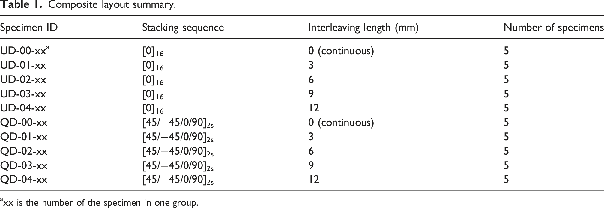
axx is the number of the specimen in one group.
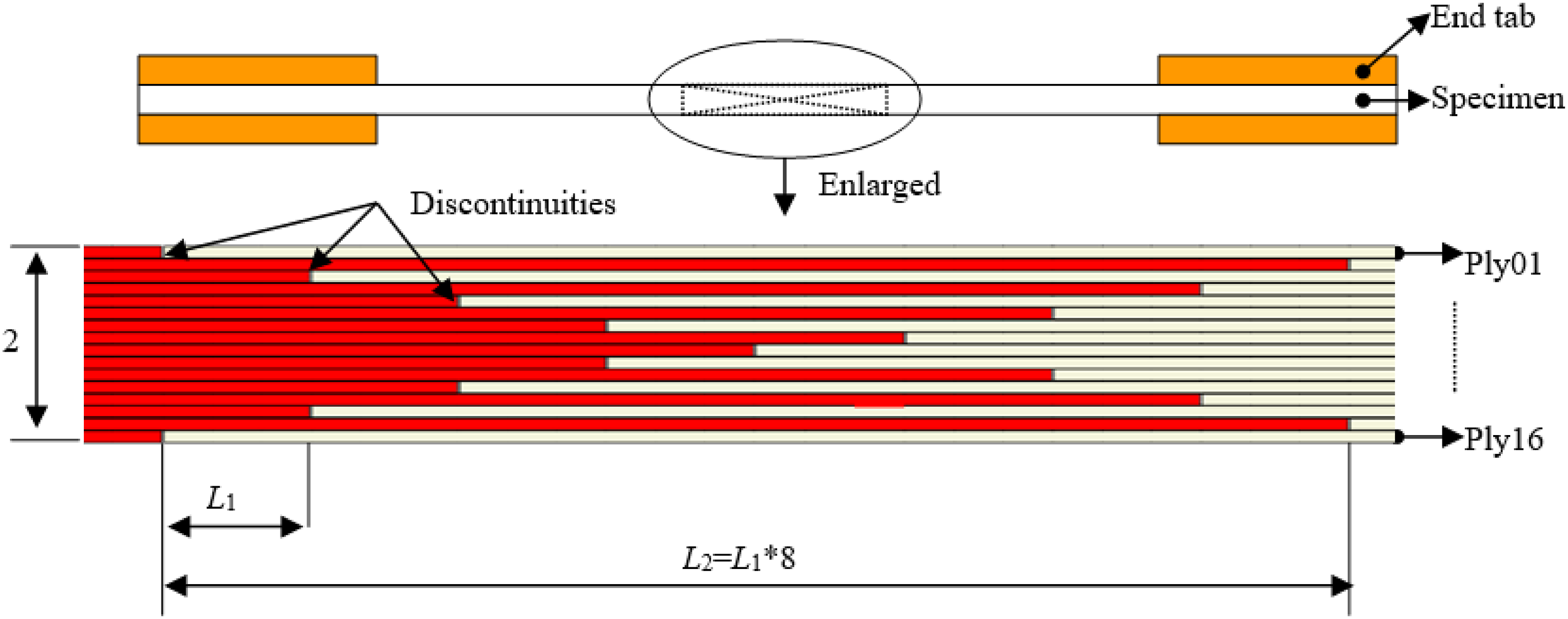
Interleaving details of the tensile specimen, side view (not to scale).
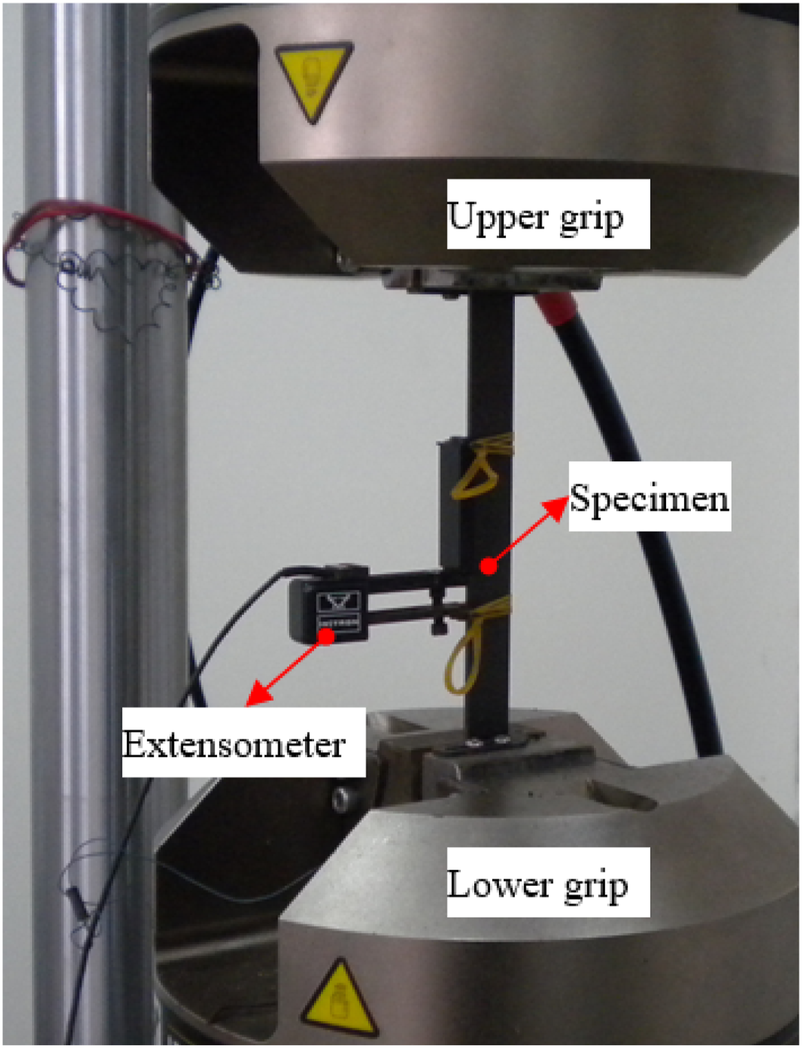
The tensile tests were conducted with a servo hydraulic testing machine, INSTRON 8801 (Figure 3). The overall deformation of the specimens was measured by an extensometer, whose gage length (L
0
) could be adjusted to cover the discontinuous segment. The displacement velocity was controlled at 1 mm/min in entire load procedure. As there are many discontinuities in the specimen, a conventional definition of the material tensile modulus is not an exact descriptive conception. So an equivalent tensile modulus (equation (1)), having the same form with the conventional one, was defined to be an indicator of the rigidity. Experimental setup.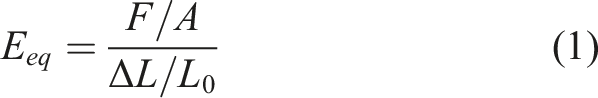
Experimental results
Testing results summary of specimens and groups.
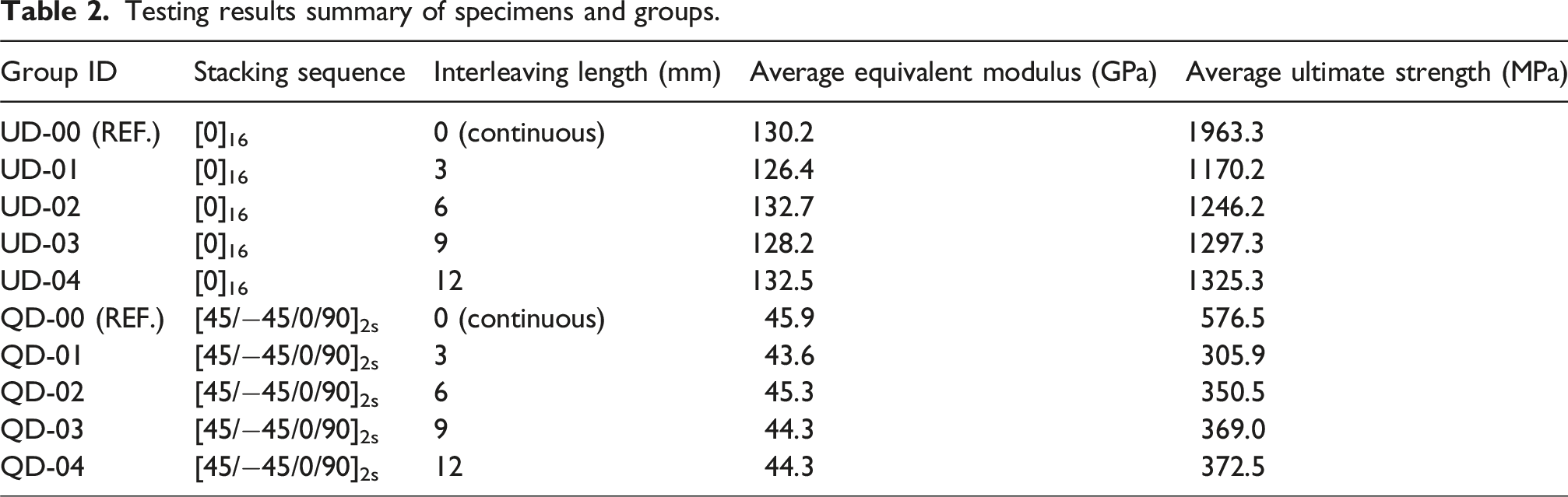
Figure 4 shows the average value and the corresponding standard deviation of ultimate strength and modulus of each group. It can be seen that strength has positive correlation with the interleaving length. By contrast, the modulus is not been affected by the interleaving length, even these values have not any remarkable distinctions with the continuous one. This result indicates that possible longer interleaving should be applied in the practical design to provide higher structure strength. Compared to the continuous fiber laminate, the interleaving would weak the structure, even though it could be applied to solve the special layup problem. In addition, the higher modulus of the interleaving layup shows the structure rigidity is maintained. The interleaving layup method could be applied in the place where the strength target is easy to meet. There is a subtle balance should be taken between lightweight and higher strength demand. Ultimate tensile strength and equivalent modulus versus various groups.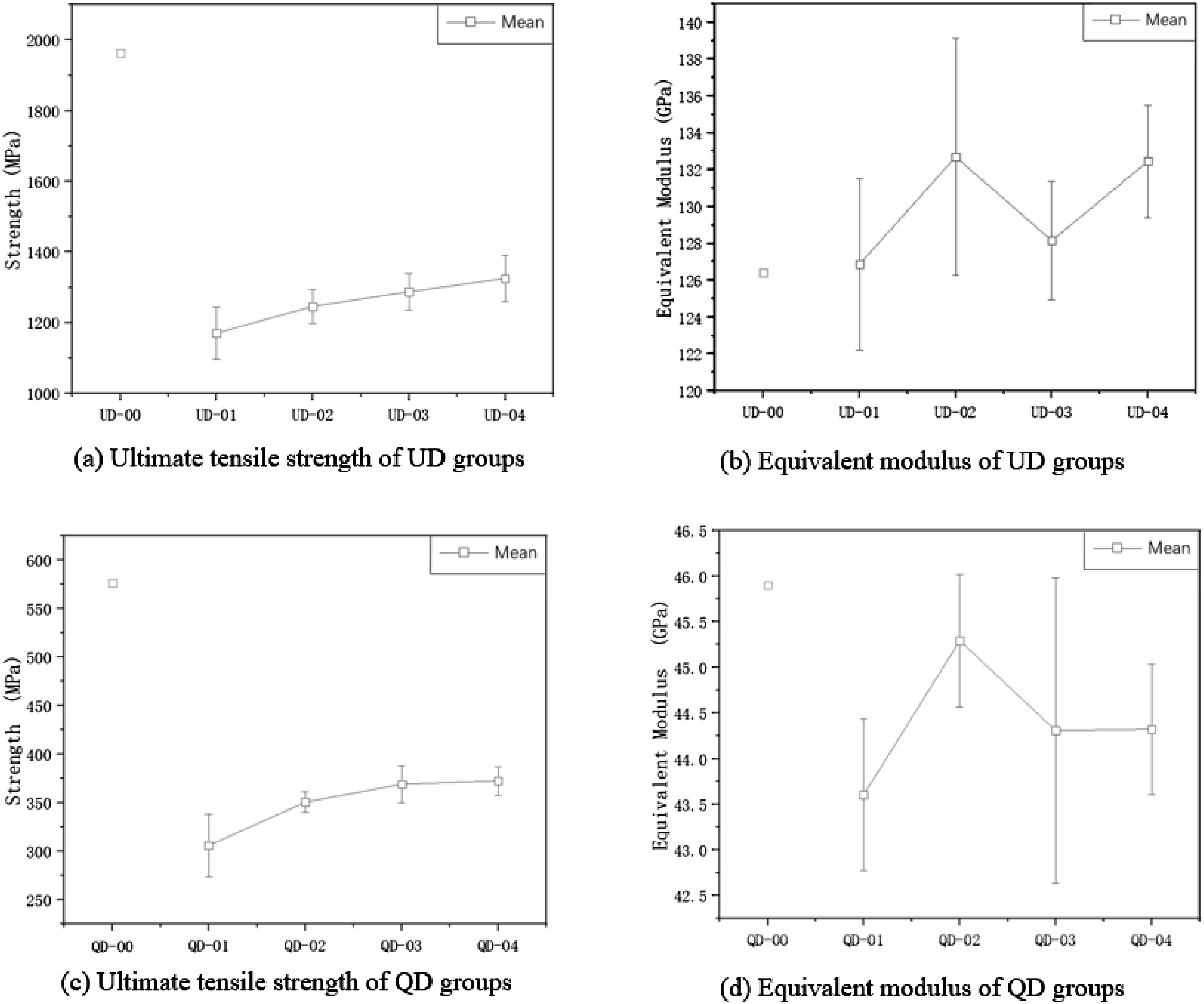
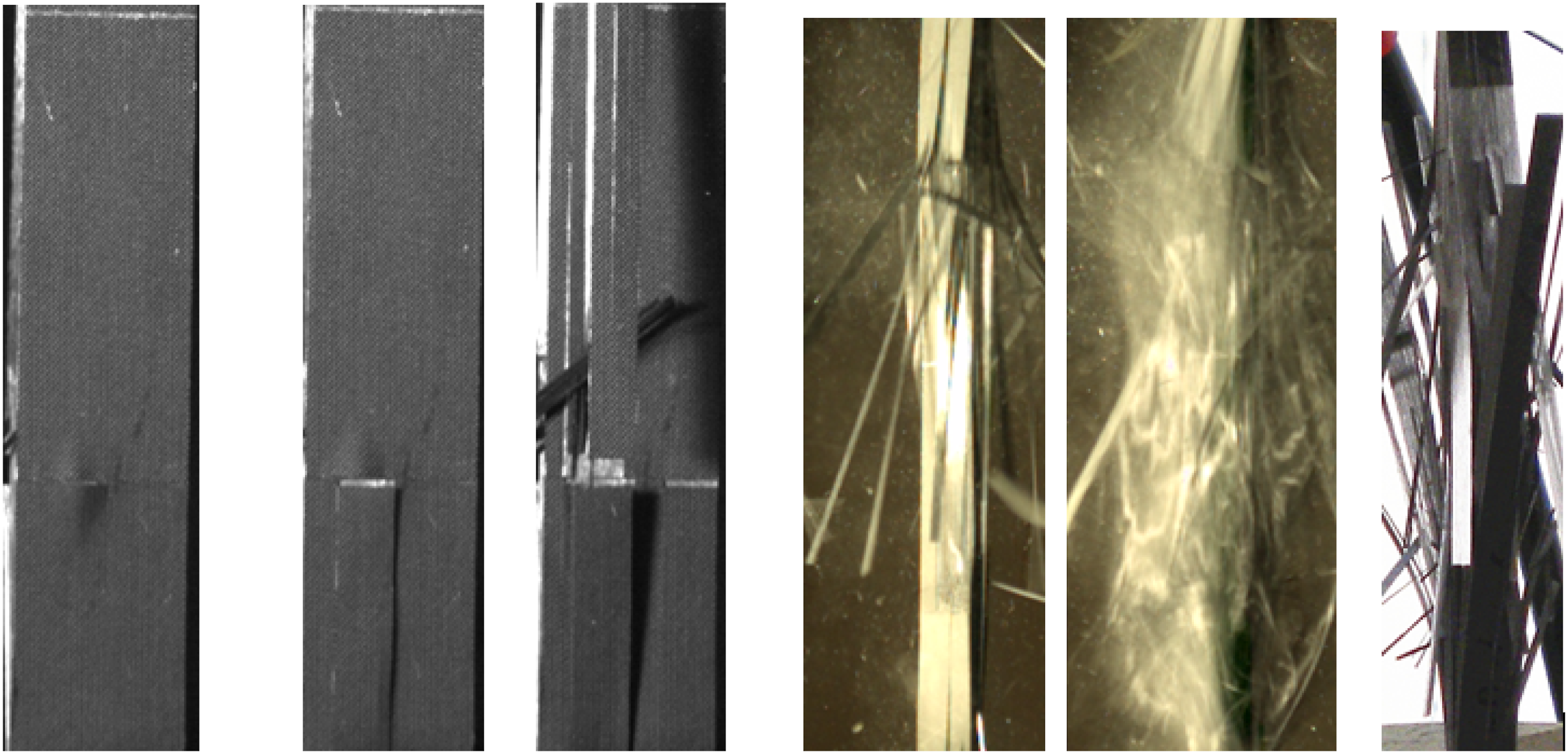
The interleaving layup have an evident linear elastic stage during the load exerting. Above the 60% ultimate load, there is a slight deviation, implying micro damage initiation (Figure 5). At that moment, the interrupted sound could be heard and become intensive, indicating the inner damage growing. For the UD specimens, there are some zigzags of load curve at the rupture moment, corresponding to final failure expanding process. This process could be proved by the graphs taken by a high speed camera at 1000 fps (Figure 6). The ply damage occurs from the surface to the inside. Firstly, the surface ply separated from surface discontinuity, and then it becomes stripped along the fiber direction. In fact, there is no real fiber breaking since the original ply is not continuous. The visible “break points” are the preset discontinuities (Figure 2). The final rupture moment looks like a sudden explosion. All the plies become stripped and all the connections between plies are broken drastically and entirely, indicating the thorough shearing fracture of the interlaminar matrix would dominate the rupturing pattern. Typical stress-strain curves of the UD and QD specimens. Rupturing process of UD-02 (high speed camera, 1000 fps), the last one is the final fracture.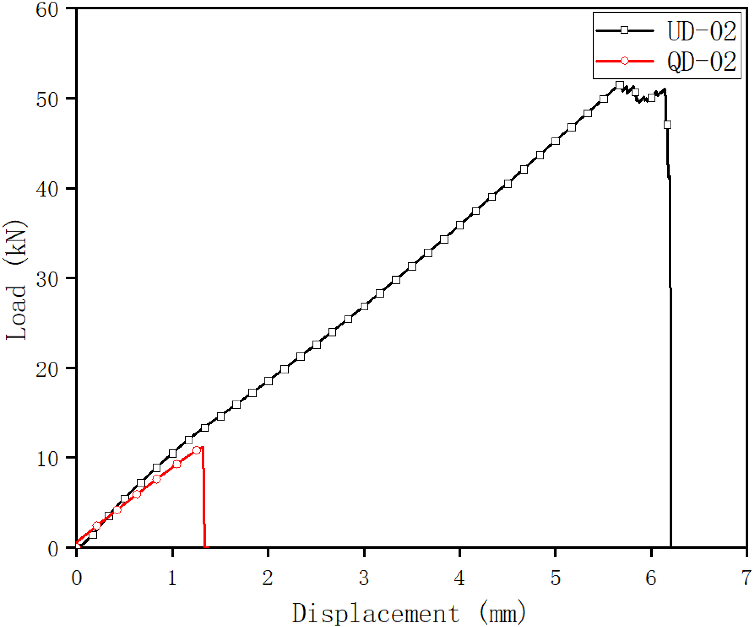
The fracture patterns of QD groups have a hybrid mode (Figure 7). The break position of each layer locates around the preset discontinuity of the current layer. However, as each layer has different fiber orientation, some of the layer is tensile damage and some is shearing damage. In these layers, 0° layer breaks due to local interlaminar matrix shearing, 90° layer breaks due to matrix tension and 45° breaks due to in plane matrix damage. These factors are mixed each other, so it has a comparative difficulty to create an effective mode to describe. Failure mode of the QD-02.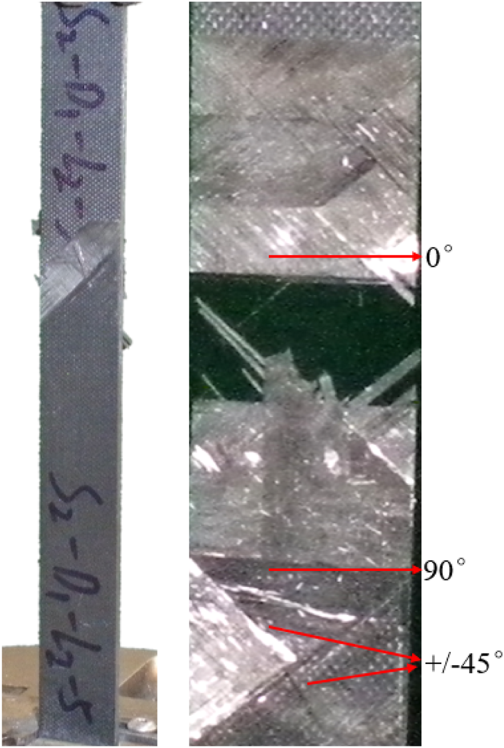
The spliced UD laminated composites with an interleaving length of 6 mm were taken and the fracture failure mode was observed by SEM electron scanning microscope. It can be observed from Figure 8(a) and (b) that the macroscopic failure is shear failure along the interleaving, but in the region around the interleaving, there is a phenomenon of fiber fracture in the adjacent layer; At the same time, multiple fiber/matrix interface cracks along the loading direction can be obviously observed in Figure 8(c). SEM scan damage fracture diagram.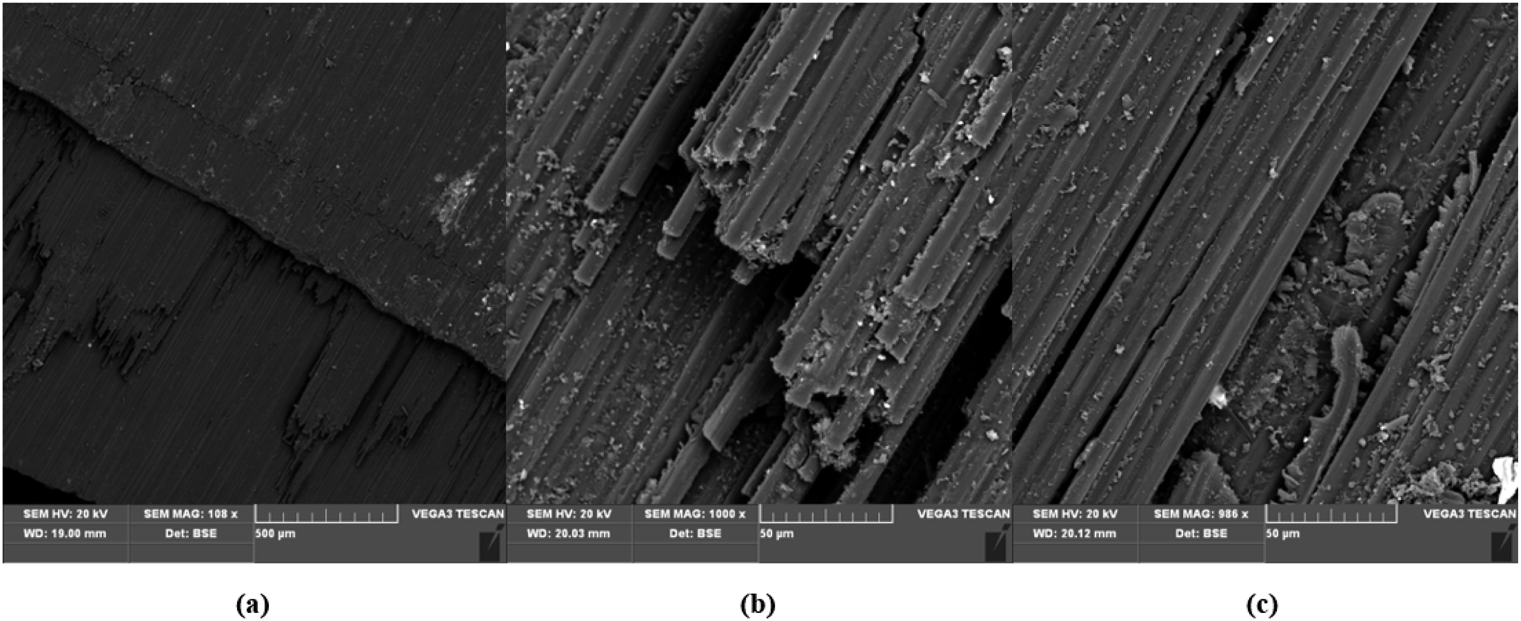
The strength assessment
Generally, for UD groups, as the load is transferred by the shear stress of the matrix, the strength of the laminate depends on the interleaving length. The estimated value of the ultimate load should be total interleaving area times the shear strength of the matrix (see equation (2)). In the equation, the τ
ult
is shear strength of the matrix, the F
ult
is load of the laminate, the l
i
is the overlapping length of each ply and w is the width of the specimen. However, it is not practical predictive method as the experimental ultimate loads are not proportional to the interleaving lengths.
In another word, the ultimate load is not only determined by the shear strength of the matrix but the stress concentration conditions around the discontinuities as well.
The real distribution pattern of the shear stress between the plies around the discontinuity could be illustrated as Figure 9. The dashed line is the stress at the early stage of the loading. The shear stress does not keep constant and it decreases rapidly, approaching to zero when it is over a specific distance (l
s
) from the discontinuity. The specific distance is called the critical distance in this paper. Inside this distance, the load would be sustained by local matrix shearing. Outside the critical distance, the load would be sustained by the fiber. For UD groups, fiber breaking does not occur until final specimen fracturing. As a result, the maximum load depend on local shearing completely. Schematic illustration of shear stress distribution of the interlaminar matrix around the discontinuity.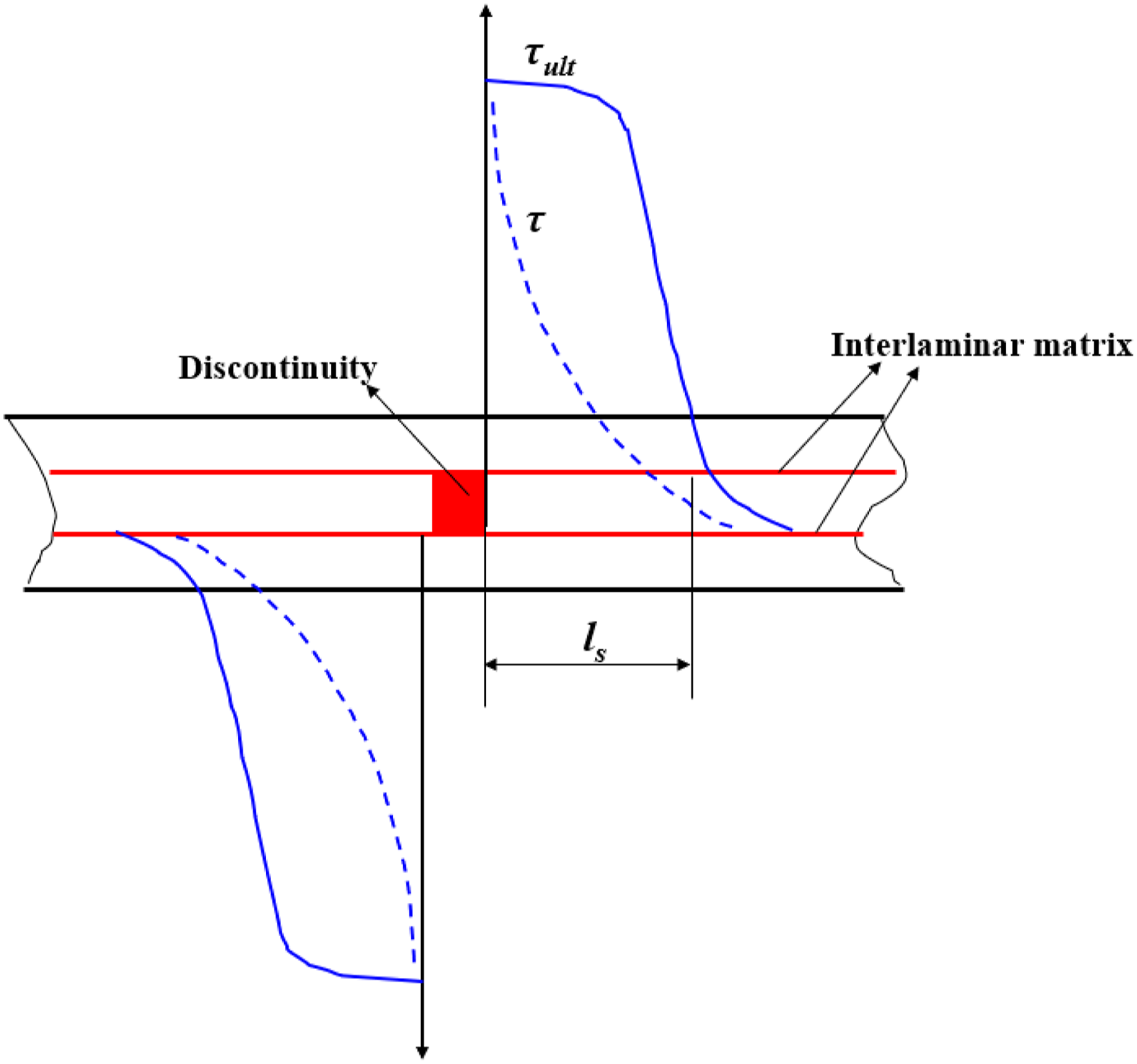
As a reaction to the external load increasing, the matrix around the discontinuity yields and hardens gradually. The ultimate shear stress could be simplified as keeping constant in the range of critical distance. So the external load is balanced by shear stress multiplying the actual area rather than the whole interface area (equation (3)).
The critical distance l
c
is considered dependent on the fiber geometries, Young’s modulus and other parameters.
26
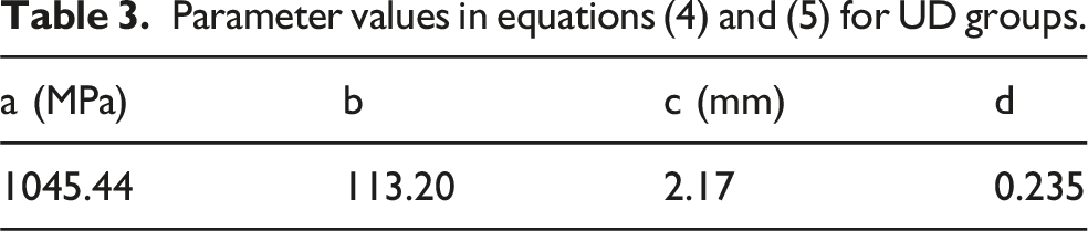
So these above parameters should be the same in group UD-01 to UD-04. However, experimental data show different group has different strength value, indicating critical distance is obviously affected by the interleaving length. Based on the results in Table 2, the relationship of interleaving length, critical distance and ultimate tensile strength could be described empirically in the following charts (see Figure 10). Following the experimental results, we could infer the above relationships might obey logarithm formulae. In another word, when the interleaving length reducing below a particular value, the tensile strength would decrease dramatically. For an instance, if the interleaving length is approaching to zero, the shearing mechanism would change into a pure tension of matrix, almost losing the entire load capacity. However, even larger interleaving length could not enhance the strength remarkably as the actual strength being controlled by the critical length, which only being affected, but not determined by the interleaving length. The predictive equations are listed as follows (equations (4) and (5)). The parameters a, b, c and d in the equation are shown in Table 3. Ultimate tensile strength and critical distance versus interleaving length (UD groups).

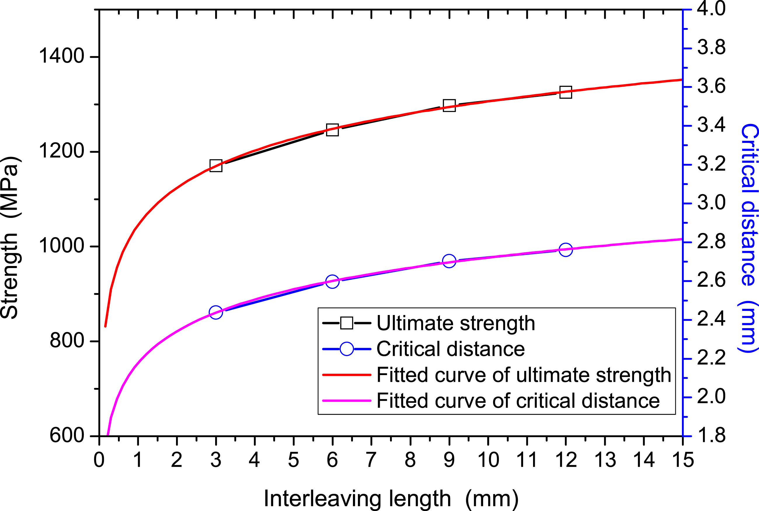
Above results show that the interleaving layup should be applied with a conservative strength prediction and as possible as larger interleaving length should be adopted but the strength potentiality is limited.
The predicted regularities about strength depending on interleaving length for QD groups have the similar patterns statistically (see Figure 4(c)). However, as mentioned above, QD groups have a different and complex damage mechanism, every layer having its different and interactive failure mode. In addition, the damage factors not only are related to ply orientation but also interleaving length. So an analytical model is hardly to proposed, more FEM simulations should be applied for further studies at micro scale.
Numerical simulations
For the special structure of discontinuous fiber composites, in order to make it more mature applied to engineering, in addition to obtaining macro and micro mechanical properties through experiments, such as strength and stiffness of discontinuous fiber composite laminates and stress concentration of matrix at discontinuous position, it is also necessary to propose a finite element model which can effectively predict tensile failure, reveal load transfer mechanism, damage initiation and evolution under the guidance of theoretical models. In this paper, the finite element numerical simulation of tensile failure test of specimens is carried out. For the special structure of specimens containing discontinuous fiber composites, a prediction model, the layer-by-layer accumulation model, is proposed. The results predicted by this model are compared with the experimental results to further verify the validity of the model, and to reveal the mechanical response, damage and fracture characteristics of the composite laminates with interleaving layup.
In order to study the strength of composites, it is imperative to establish the mathematical expression of damage to predict the strength. The damage initiation and evolution eventually lead to the failure of composite materials.
Damage theory of composite laminate
Damage initiation
In ABAQUS, the damage initiation criteria of carbon fiber reinforced composite are based on Hashin theory. These criteria consider four different damage initiation mechanisms: fiber tension, fiber compression, matrix tension, and matrix compression.
The initiation criteria have the following general forms:
Fiber tension (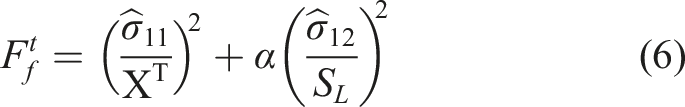
Fiber compression (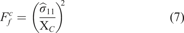
Matrix tension (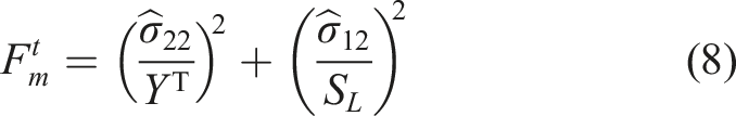
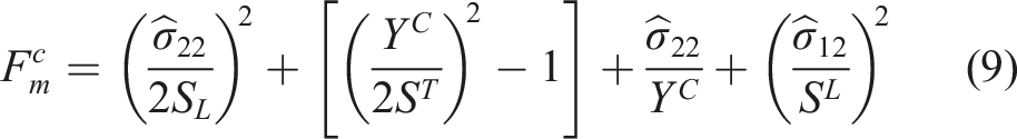
In the above equations:
Damage evolution criterion
Damage evolution specify the starting point of material failure, and the material is in the linear elastic stage before the damage begins. Damage evolution is the evolution of the material after the point of failure, after which the stiffness of the material gradually decreases until fracture. The stress of the material at this stage is calculated by the following formula:
In equations, 
In equation,
Modeling
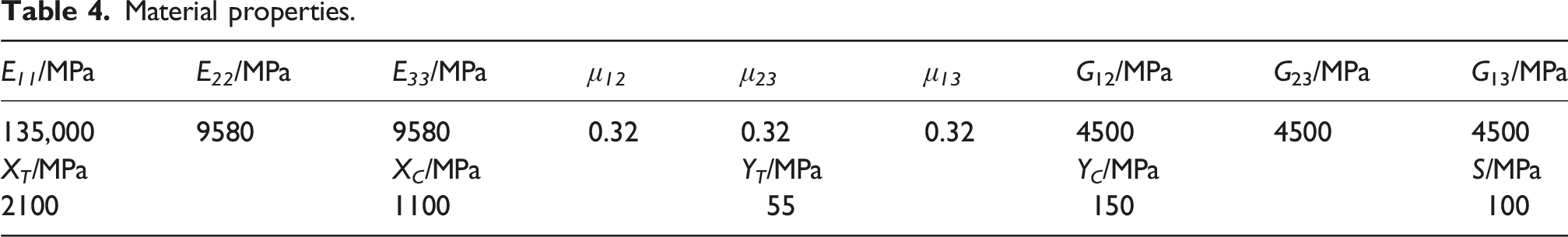
In this paper, considering that there are discontinuities in the composite laminates, and the location of discontinuities in each layer are different, a model based on the details of the laminates is considered to simulate this special laminate structure effectively. In this model, there are 16 layers of laminate, shell element are used to simulate each layer. In order to simulate the discontinuity of layup of real specimens, 0.3 mm length of elements are cut out at corresponding positions in each shell element, and the spatial arrangement of discontinuity positions of layers is shown in Figure 11. Figure 11 shows the finite element numerical model of discontinuities composite laminate. The layup element type of composite laminate is SC8R element, the interface between layers is simulated by 0-thickness cohesive interface elements. According to measurements, the average dimensions of the test specimens were 249.95 × 14.06 × 1.96 mm. Therefore, the dimensions used in the modeling were set to 250 × 15 × 2 mm. Based on a mesh sensitivity analysis, an element size of 3 mm was selected. The material properties are shown in Table 4. In order to simulate the actual failure mode, Hashin criteria are used to predict the onset and evolution of damage sites. Layer-by-layer accumulation. Material properties.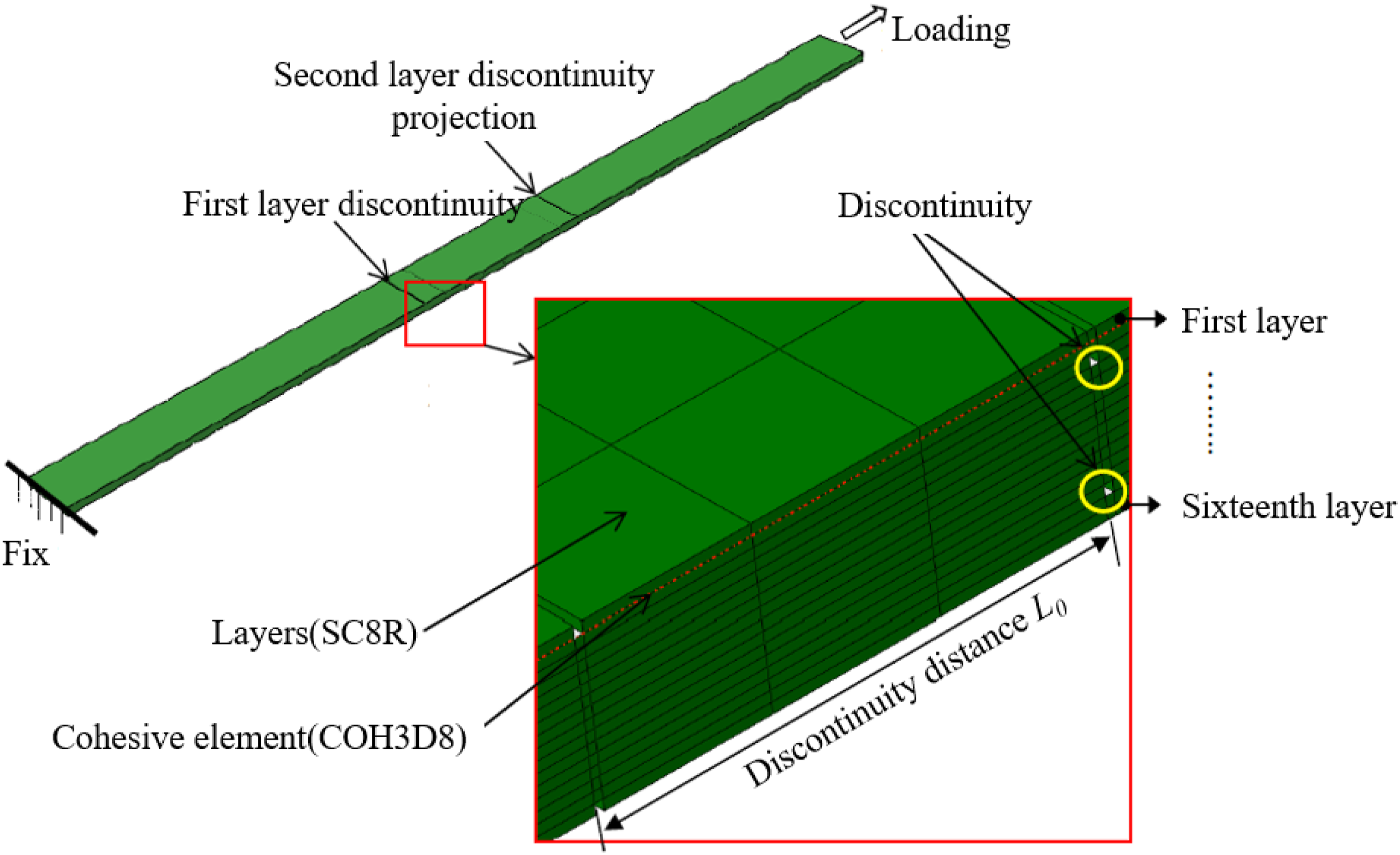
Analysis result
The simulation analysis of two different layup methods of composite laminate with a discontinuities distance of 6 mm was carried out in this paper, and compared with experiment, the results as follows.
The result of UD-02 group
The failure mode of UD-02 group in Figure 12, it shows that the first layer layered fracture, and the severe delamination in the discontinuities area is consistent with the experiment. The failure mode of UD-02 group.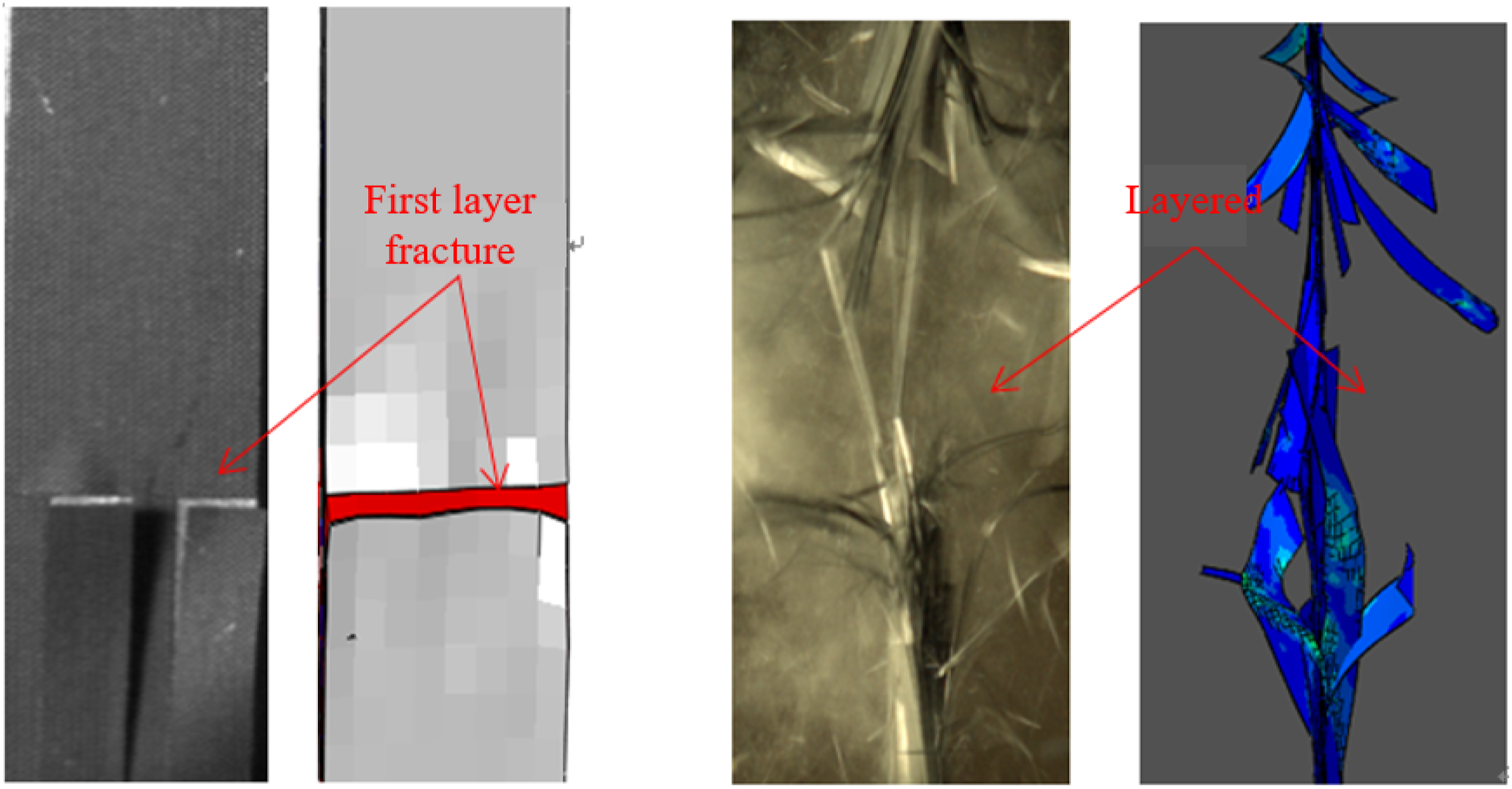
Figure 13 is the load-displacement curves of the experiment and the simulation, and the normal deformation distribution of the specimen is attached to characterize the macroscopic deformation status of specimen. The simulated failure load of the specimen is 47.11 kN and the strength is 1570 MPa. The tested strength is 1575 MPa and the error between simulated and experiment is 0.3%. The load-displacement curves of the experiment and the simulation of UD-02 group.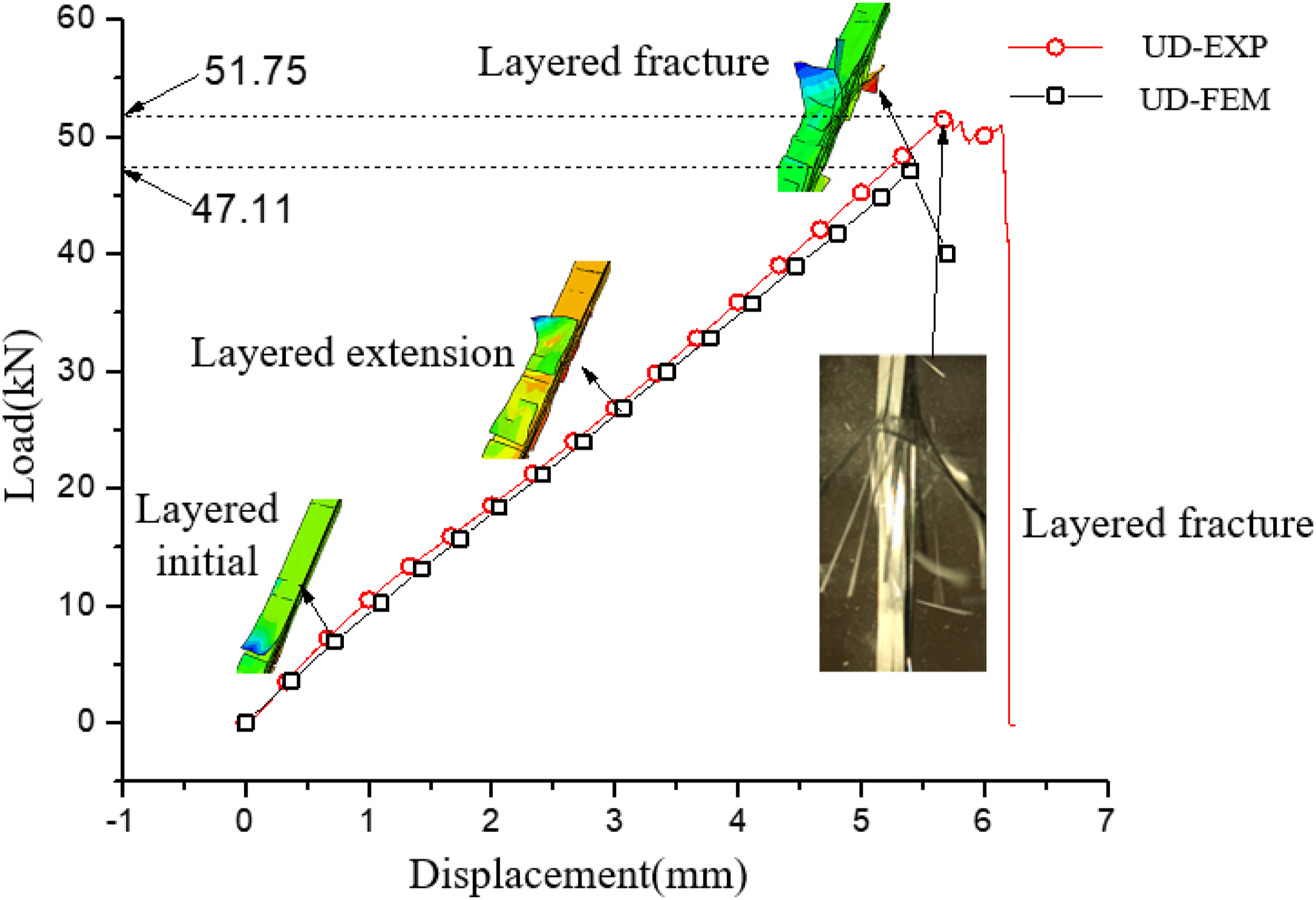
Figure 14 is the stress-strain curves of experiment and simulated. The elastic modulus of the simulated is 122 GPa, the experiment is 135 GPa, and the error between experiment and simulation is 9.6%. The small error of experiment and simulation results furthermore verifies the effectiveness of the simulation method in this paper. The stress-strain curves of experiment and simulated of UD-02 group.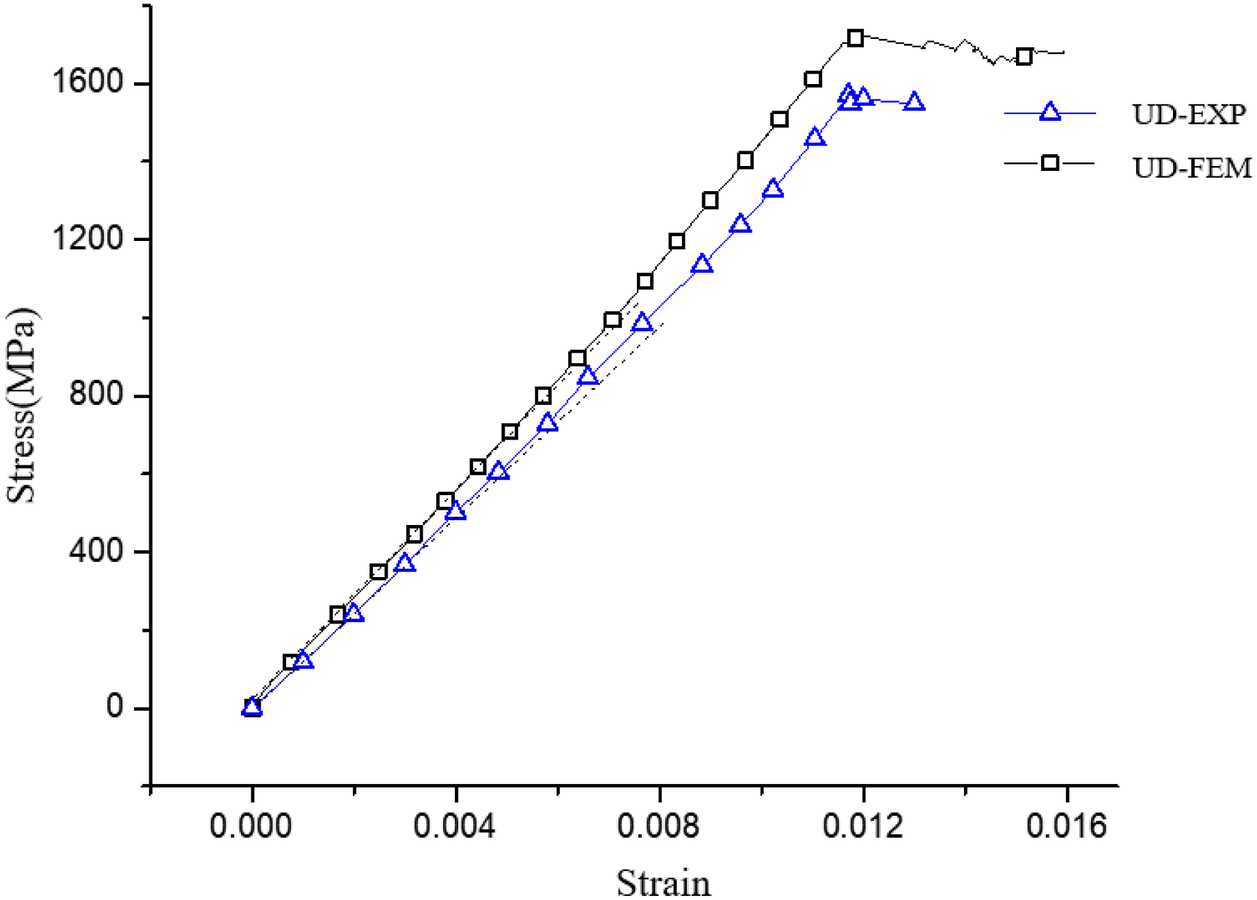
The result of QD-02 group
Figure 15 shows the failure mode and displacement distribution along the tensile direction of the QD-02 group. As shown in Figure 15(a) and (b), the fracture of specimen is relatively flat, and the laminate are shear fractured. The failure mode of simulation and experimental are coincident. Figure 15(c) shows the failure distribution of cohesive interface element, with blue representing non-damage and red representing failure. It can be seen that the failure of cohesive interface element simulates the true layered failure of specimen. The failure mode and displacement distribution of QD-02 group.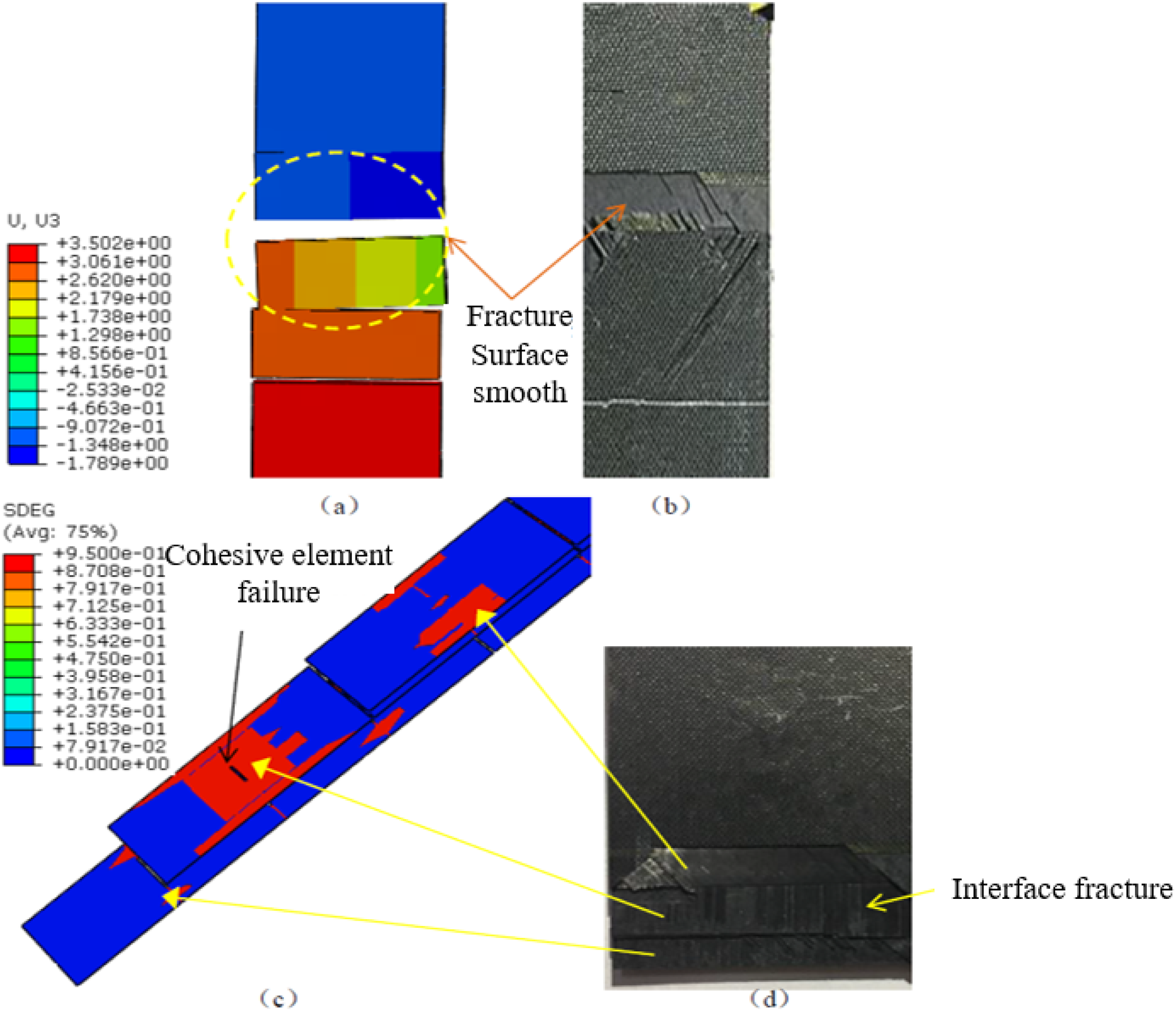
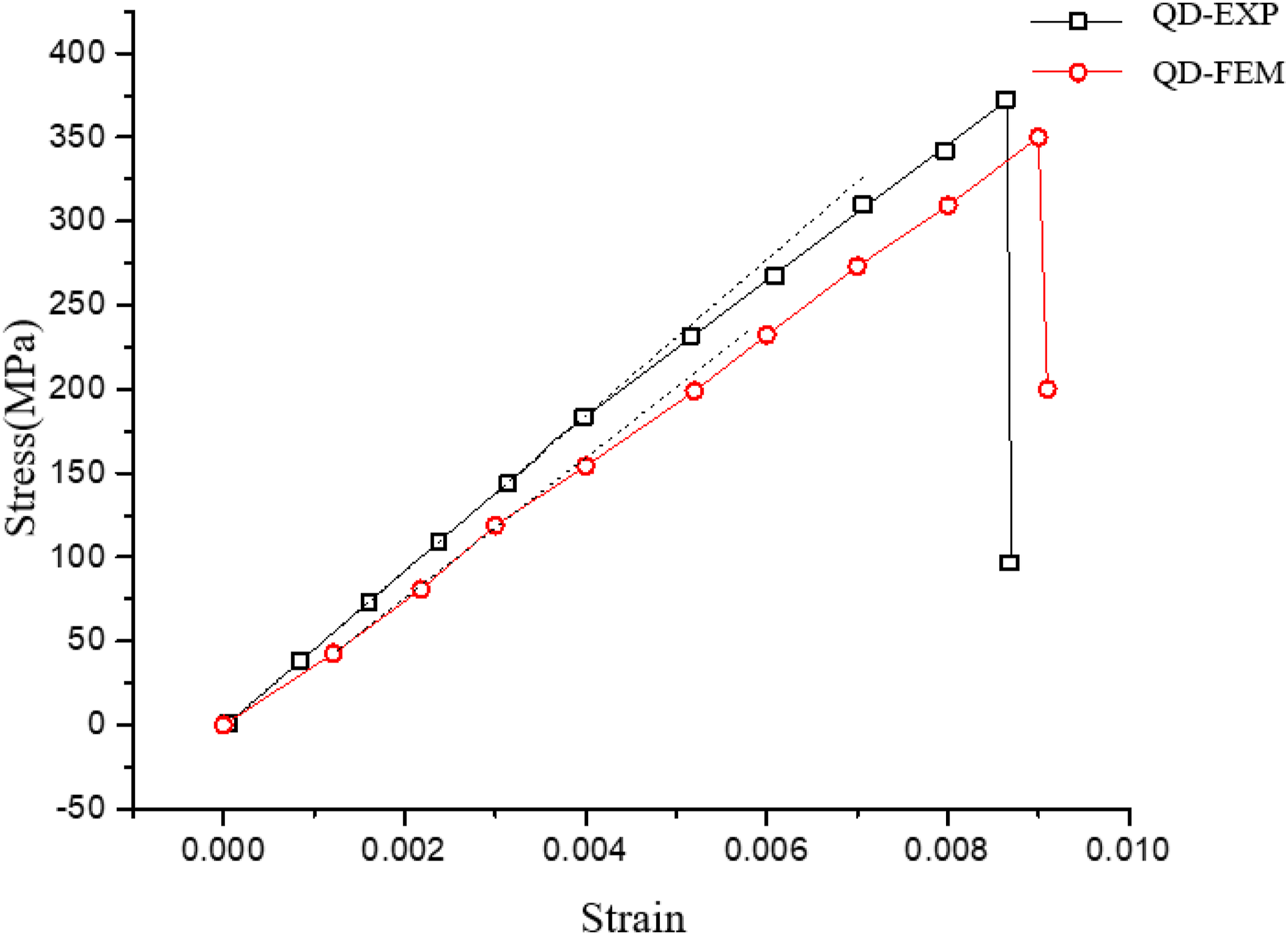
The strength and elastic modulus obtained by simulation and experiment of the specimen are compared. The load-displacement curve is shown in Figure 16, and the simulated stress concentration distribution is attached to the figure to represent the macroscopic deformation. The stress-strain curve of the specimen obtained by the experiment and simulation is shown in Figure 17. The failure load of the specimen obtained by experiment is 11.16 kN, strength is 372 MPa, and elastic modulus is 43.26 GPa. The simulated failure load is 10.2 kN, strength is 340 MPa, elastic modulus is 40.1 GPa, the error of the strength simulation is 8.6%, and the error of the elastic modulus simulation is 7.3%. The small error indicates that the results of the finite element numerical simulation are in good agreement with the experiment. The load-displacement curves of the experiment and the simulation of QD-02 group. The stress-strain curves of experiment and simulated of QD-02 group.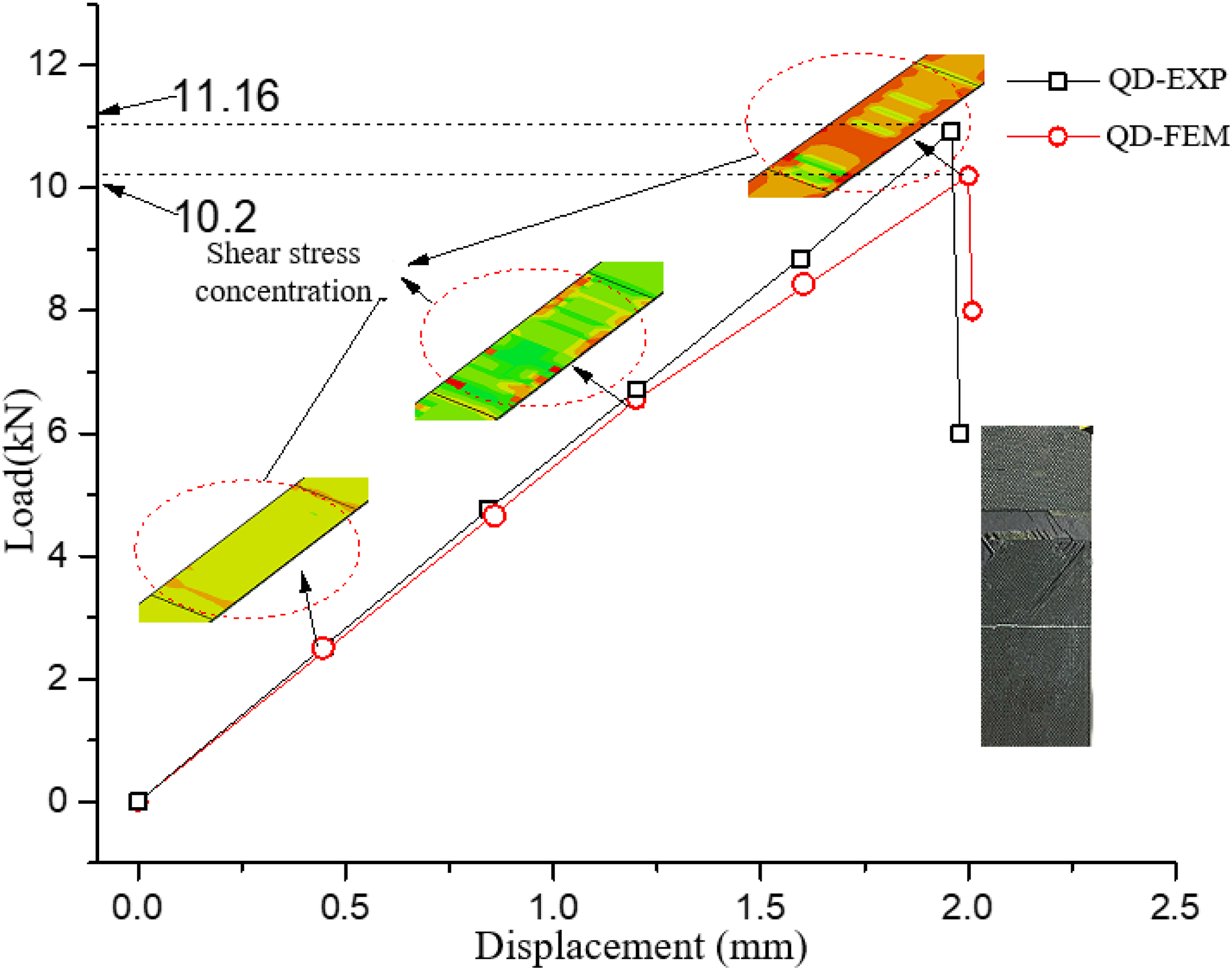
Summary
A variety of composite tensile specimens with various layups and interleaving length were manufactured and tested. The mechanical properties such as strength, Equivalent Young’s module was measured. Meanwhile, the damage characteristics and corresponding mechanisms were discussed. (1) Comparing continuous the fiber composite, the interleaving ply composite has lower strength and comparable and stable Young’s modulus. As having more flexible layup pattern to meet the special needs, it can be applied at the place where the strength could be satisfied easily. (2) The load transferring and fracture mechanism of interleaving ply composite is different from continuous fiber composite. For UD groups, local matrix shearing and corresponding damage around the discontinuity are the main factors. So a conventional strength prediction is hardly to be applied. (3) The strength of the interleaving ply composite is affected significantly by the interleaving length, indicating logarithm relations between them. More mechanism based analyses are in needed further.
Footnotes
Funding
The authors disclosed receipt of the following financial support for the research, authorship, and/or publication of this article: The authors gratefully acknowledge the financial supports from National Defense Science and Technology Key Laboratory Equipment Development Foundation (Grant No: 6142704200405).
Declaration of conflicting interests
The authors declared no potential conflicts of interest with respect to the research, authorship, and/or publication of this article.
Data Availability Statement
Data sharing not applicable to this article as no datasets were generated or analyzed during the current study.