






Abstract
The present study deals with the ozone treatment of natural fibres with varying cellulosic contents. The main advantages of performing ozone treatment of cellulosic materials are that it reduces the usage of water, energy and time, since it can physically bleach the cellulosic materials without the need for these essential resources. Also, ozonisation limits the harmful impact on our ecology, basically the chemical oxygen demand values, of the various processes. In addition, ozone treatment is also practiced in the field of natural composites, medical sectors, and in other textile processing areas. In addition, we have mentioned about an industrially scalable machine i.e., ball milling machine required to produce particles from such fibres. This machine can produce sufficient quantity of particles in a quite reasonable amount of time. Furthermore, we have also observed that by ozonising the fibres, makes them more prone to breakage due to removal of lignin and other impurities along with a decrease in their surface energy, making them more brittle. After preparation of the particles we have made composites at different particle loadings and compared their properties with neat ozone treated jute fabric composites. Finally, a brief comparison has been made in terms of creep with composites loaded with different natural fibre-based fillers. The results demonstrate that the ozone-treated jute fabric composite reinforced with sisal filler shows better performance compared to the other natural fibre-filled composites.
Introduction
Recently, the textile structural composites gained importance for load bearing applications in ships, automotive, aerospace, wind energy, etc. industries because of their greater strength‐to‐weight ratio, high corrosion resistance, and fewer maintenance. 1 Further, the interest in bio-based materials also attracted attention due to rise in environmental concerns and sustainability. 2 For instance, the plant fibres are becoming more popular as reinforcements in composite manufacturing due to their biodegradability, low density, and cheaper cost. 3 The plant fibres are gradually replacing the synthetic fibres as reinforcements for the development of environment friendly products (door trim panels, engine and transmission enclosures, etc.). 4 However, the plant fibres have few limitations over synthetic fibres especially in textile structural composites (subsea equipment, airplane and the oil gas industry, etc.), where they need to demonstrate superior long term mechanical performance to cyclic (fatigue) as well as long term constant load (creep) situations in harsh environments of varying temperature and humidity levels. 5 The plant fibres exhibit pronounced viscoelastic behaviour in textile structural composites, unlike pure elastic behaviour of carbon and glass fibres. 6 Furthermore, the mechanical response of structural composites is time and environment dependent due to the viscoelastic behaviour of the polymer matrix. 7 This could result into dimensional instability and even structural failure of composites due to poor creep properties. Creep (a progressive deformation of a material at constant stress) is very important end-use property for material applications requiring long term durability and reliability. 8 In this context, several surface modification methods have been used on lignocellulosic fibres in the past to alter the surface roughness of the fibres and enhance their thermal stability, mechanical/structural properties and interfacial interaction with matrices. However, most of the reported methods are not environment friendly besides requirements of more water, energy, and time. 2 Therefore, further research is required to investigate the suitability of alternative surface modification methods. In present chapter, the ozone surface treatment was chosen as an alternative surface treatment to remove the non-cellulosic materials from jute fibres, and thereby obtain a higher surface energy, better sorption properties and superior interfacial fibre-matrix interaction/adhesion.3,9–11 It has been found that most of the polymer matrices used in composite applications show creep behaviour, at ambient temperatures as well as high temperatures. In particular, when the matrix is stressed, its free energy is raised, then the polymer segments gradually reorient, coming back to a lower energy rate. In case of polymers, where glass transition temperature is above ambient temperature i.e., in polyolefins, the viscous resistance to reorientation of chain segments is normally easy to overcome. 12 On the other hand, for polymers operating at the glassy state, the viscous resistance to the reorientation of chain segments will be very high, with the polymer matrix behaving like a brittle solid. The latter is usually the case of lignocellulosic fibres. In this context, a study reported on flax and nettle fibres when subjected to tensile loading showed a measurable effect of environmental humidity over the progression of their creep behaviour. 13 This combined presence of two polymers as the matrix and the fibre (cellulose itself is a polymer), which is the case for plant fibre composites (PFCs), acting differently if not with contrasting modes as regards dynamical behaviour, hence creep, is inherent to the nature of these matrix and fibre materials. More precisely, plant fibres can be considered as hierarchical cellular composites, according to the definition by Lakes (1993). 14 In practical terms, a reasonably clear example of the arrangement of a technical lignocellulosic fibre sisal. 15 In the specific case, they are formed by cellulose, hemicellulose and lignin, all of which are polysaccharides, though with very different structural arrangements and properties. For this reason, they include in themselves softer and harder parts, which can be again schematized as acting as matrix and fibres, therefore ideally forming a suitable bonding of uniform strength, in other words an interface. A consequence of this is that, as stated earlier, a plant fibre is itself a polymer and therefore subject to viscoelastic behaviour. To summarize these first observations, it can be reasonable to assume that in fabricating PFCs, both the matrix (a polymer) and the reinforcement (a hierarchical natural fibre) would present viscoelastic behaviour. It will be not obvious therefore to lead to a reasonable prediction of the sum of the different effects (from plant fibres and from the matrix polymer) over the behaviour of the PFCs in service, hence over a suitably long period of time. These considerations justify the study of this topic for the practical application of plant fibre composites. On the other hand, only a limited number of investigations have been carried out on the subject of viscoelasticity of PFCs, which mainly cover only the most frequently used plant fibres.
Moreover, there is limited literature available on theory/model which can accurately predict the long-term performance and creep behaviour of natural fibre based structural composites. Further research work is therefore required to understand and develop the reliable models for the estimation of lifetime assessment of natural fibre based structural composites especially under different environment conditions. In this research work, we try to understand and develop the long-term durability of plant fibres-based textile structural composites during their service lifetime and exposure to aggressive environments conditions and to get a comparative idea on creep properties of different cellulose based plant fibres i.e., cornhusk, jute and sisal. After gathering such advantageous properties obtained from cornhusk fibres, in this research paper we will discuss about the extraction of corn husks fibres and then optimize the ball milled particles taking various conditions of the ball milling machine i.e., ball to material ratio, milling time and milling speed. This ball milling technique has many advantages over other mechanical treatments as it easily provides nanocellulose in bulk quantity at room temperature and produces sufficient amount, thereby making it industrially scalable. Also, we could find from our results that after the fibres are ozonized, the particle size reduces drastically after being milled as seen from the SEM images. Furthermore, composite properties of neat ozone treated and cornhusk, jute and sisal filler loaded jute fabrics are evaluated. Therefore, this article can give us a complete idea on the various advantageous properties exhibited by ball milling process and the benefits of performing ozonation on such fibres, which are all of low cost and industrially viable approaches.
Experimental methods
Materials

Extraction of cornhusk fibres
The fibre extraction involves various steps, as discussed by various researchers in their published works.18,19 At first, the material is prepared, which involves the selection of raw cornhusks, then cutting them and finally treating them chemically, as shown in Figure 1. The cutting of the raw materials should also be practiced in the following fashion i.e. only the outer shell between 1 and 5 layer should be selected, since it depends on the age of the corn husk. If it is too ripe then the first layer should be peeled off and the outer layer from 2 to 6 should be selected. After selection, the cornhusks should be cleaned with water to remove dust and impurities and kept to dry in ambient condition for 1 day. Secondly, the dried cornhusks were chemically treated with 1 L of water per 5 g of sodium hydroxide. After that, water should be boiled for 1 h at 90°C–100°C. It should not be over 100°C and the cornhusks should be stirred for 1 hour until it becomes soft and tender. Finally, after chemically treating the husks, they should be washed for 3-4 times to remove all remaining chemicals and dried by using a thin cloth. Then the dry fibre weight should be measured and kept to dry in the sun. Schematic diagram showing the process flow to extract fibres from cornhusks.
Ozone treatment of plant fibres
Before conducting the ozone treatment, the delignified cornhusk, sisal and jute fibres were pre-humidified by dipping them in water. The treatment with ozone gas was done by keeping the plant fibres for 5, 10 and 15 min inside an air-tight glass container comprising of ozone gas. It was linked with an ozone generator manufactured by Eltech Ozone an ISO 9001: 2015 certified Indian Company situated in Mumbai, India. The ozone gas was released by corona discharge principle with an ozone output rate of 5 g/h and concentration of ozone in the range of 70–120 mg/L. The oxygen gas to produce ozone gas was generated by another closed container placed just below the ozone generator with an oxygen flow rate of 3 L/min.3,10
Characterisation of the plant fibres
Surface microstructure
The scanning electron microscope Sigma, Zeiss, EV50, Germany was used to see the surface microstructures of untreated and ozone treated plant fibres at an accelerated voltage of 20 kV under different magnifications from 500x to 2000x. The fibre surfaces were gold coated with the help of plasma sputtering instrument before the SEM images were taken.
Mechanical properties
Fibre elastic modulus was measured according to ASTM D 3822 standard test method for single textile fibres. 18 At least 11 specimens of each fibre set were measured at a crosshead speed of 15 mm/min. Gauge length was set at 2.54 cm. A 10 N load cell was used. The measurement device was Instron Tensile Tester, 3365R2849, Assembled in USA.
Ball milling of plant fibres
High-energy planetary ball mill of Retsch PM100 was used with sintered corundum container of 50 ml capacity and zirconia balls of 5–15 mm diameter for milling in a dry atmosphere. The ball mill was loaded with ball to material ratio (BMR) of 15:1 maximum. The rotation speed of the disc was kept at 650 rpm maximum with reverse rotation of containers. Ball milling process relies on the principle of energy release at the point of impact between balls as well as on the high grinding action created by friction of ball on the wall. 20 The ball milling process was established at three different machine parameters i.e. ball to material ratio, milling time and milling speed (1:15 BMR, 180 min, 650 rpm).
Fabrication of composites
The hand layup technique was utilized to prepare the composites of neat ozone treated jute fabric/epoxy (OJF + E), ozone treated jute fabric/epoxy/cornhusk particle (OJF + E + CHP1, OJF + E + CHP3 and OJF + E + CHP5). Similarly, ozone treated fabric/epoxy/jute and sisal (OJF + E + JP1, OJF + E + JP3 and OJF + E + JP5) and (OJF + E + SP1, OJF + E + SP3 and OJF + E + SP5) were prepared. Each of the composites was fabricated from three different layers of jute fabric with unidirectional configuration of each layer. Before starting the process, the weight ratio of resin and hardener was kept at 90:10 as recommended by the manufacturer and weighed amounts based on jute fabric of pulverized plant fibres under 1, 3 and 5 wt.% were mechanically mixed with epoxy resin at room temperature until a homogeneous mixture was obtained. The mixture was then poured on each layer of fabric and uniformly spread by using a hand roller. The rolling by the hand roller resulted in uniform wetting of the jute fabrics and enabled the squeezing of the excess resin. The composite setup and Teflon coated sheets were kept in between steel plates and finally cured at a temperature of 120°C for a duration of 1 hour inside an oven having a predetermined mass kept on it to keep a uniform pressure of 50 kPa.
Creep testing of composites
The Q800 Dynamic mechanical thermal analysis instrument of TA instruments (New Castle DL, USA) was employed to perform the short-term creep tests in three-point bending mode at temperatures 40°C, 70°C and 100°C. The static stress of 2 MPa was applied at the middle portion of composite sample for 30 min after equilibrating at the desired temperature. The resulting creep strain was measured as a function of time.
Estimation of creep behavior of composites
The OriginPro 9.0 software was employed for fitting the experimental date to various creep models using non-linear curve fit function. The best fit was decided based on higher values of coefficient of determination (R2) closer to one.
Findley model
It has been reported to demonstrate the non-linear creep behaviour of viscoelastic materials as given in equation (1).
21
This model can be suitable for estimation of long-term creep behaviour; however, it has limitation to describe the creep mechanism.
Burger’s model
Burger’s Model consists of four different parameters. It is used to define the relationship between the composite morphology and their behaviour towards creep. This model is comprised of combination of Maxwell element and Kelvin-Voigt element arranged in series and parallel. The total creep strain can be divided into three different portions such as 
The equation (2) can be written as equation (3)
The four parameters 
The Burger’s four-parameter model is advantageous as it provides qualitative explanation of all phenomena found in viscoelastic materials like instantaneous elastic strain, retarded elastic strain, instantaneous recovery, retarded elastic recovery and permanent deformation. However, the limitation of this model is that it can be used for characterization within a certain test duration only and therefore may not have direct physical meaning in explaining the viscoelastic properties of composites.
Coupling model
Despite good fitting of experimental data, the previous creep models still encountered great difficulty to establish the connections between the parameters, the physical meaning of components and the loading conditions. The mobility and entanglement of polymer segments, which are important factors governing creep behaviour of composites, are dependent on the interactions between fibres and matrix in the composites. Here, interestingly, the coupling model has capacity to physically characterize the features of segmental mobility from coupling parameter (
As the
Nanoindentation of composites
The aim of the nanoindentation experiment was to extract elastic modulus and hardness of the composite materials from load displacement curves. Nanoindentation test was carried out to measure the mechanical properties of prepared composites at nano or micro scale using Industron NanoGuru NG50 having three-sided Berkovich diamond indenter of 50 nm tip radius. The instrument had an indenter head, a scanning probe microscope connected to capture the position of the indent made on the polymeric composite. The in-situ scanning probe microscopy (SPM) facility gives high resolution images to realize structure-property correlation of a given material at nanoscale. All composite samples after being prepared were polished successively using Buehler microcut silicon carbide grinding paper. The indenter was programmed to carry out a series of five indents along the matrix–interphase–fiber. The spacing between individual indents was carefully selected as 3 μm so as to avoid overlapping of the plastic zone of neighboring indents. The loading and unloading rates were fixed at 10 mN/min, whereas the approach speed was kept at 1000 nm/min. A maximum load of 5 mN was used for the tests. The acquired remnant prints were further investigated for surface topography of indented marks by SPM.
The load-penetration measurements were analyzed using Oliver and Pharr Equation,
24
where reduced elastic modulus, Schematic showing nanoindentation test.


Interfacial shear strength of composites
The microbead method was used to calculate the interfacial shear strength between epoxy resin and the reinforcement.25,26 The specimen was prepared by putting a tiny drop (microbead) of the precured epoxy resin onto jute yarn which was then dried in an oven (see Figure 2(a)(I)). Furthermore, we have also mixed cornhusk, jute and sisal particles (CHP, JP and SP) of different loadings (1%, 3%, 5%) in the resin and dropped on the jute yarn surface, as seen in Figure 3(a)(II). The microscopic images are obtained from an optical microscope ZEISS. The interfacial shear strength was calculated using the Instron universal tester employing microvise plates. The position of microbead was adjusted so that it was just lying under the microvise plates (see Figure 3(b)). The one end of jute yarn gripped by Instron at load of 0.03 mN was moving at speed of 5 mm/min, whereas another end was left ungripped. The interfacial mechanical properties were determined from the load displacement curve, the maximum pull out and post de-bonding force.
27
The shear force required to shear that microbead was measured and an average interfacial shear strength was calculated using equation (8). Measurement of interfacial shear strength of jute yarns
28
.

Results and discussions
Effect of ozone treatment on properties of plant fibres
Surface microstructure
The surface microstructures of the untreated, 5 min, 10 min and 15 min ozone treated cornhusk fibres are shown in Figures 4, 5 and 6 (a,b,c,d). It shows the extent of defibrillation and the pore structure of the fibres after being ozone treated. From the figures, we can clearly observe that the untreated fibres possess a compact structure, whereas, the ozone treated fibres demonstrates defibrillation and presence of pores in the fibre structure. Furthermore, Figures 4,5 and 6 (b,c,d), illustrates that as the ozone treatment time increases the extent of fibre rupture elevates. Therefore, we can say that ozone treated 15 min fibres shows the highest degree of defibrillation and larger size of pores, which may cause more deterioration to the fibres. So, we have taken 10 min ozone fibres for further analysis of our results, since it showed more or less desired properties.
28
Similar work carried by a group of researchers stated a similar work on the surface microstructures of untreated and alkali-treated jute fibers that were evaluated using a SEM instrument. The reason for such smooth surface of the untreated fibres was due to the fact that they are covered with pectin, wax and impurities, which may reduce the contact area between jute fibres.29–31 Furthermore, it was reported that there are many wrinkles on the surface of treated jute fibers.
32
These micro-voids and gaps provide access to the epoxy resins, which is beneficial for improving the interfacial compatibility and mechanical properties of the composites. Also, it was found with alkali treatment the surface of jute fibres become clean and rough due to removal of pectin, wax, impurities and disruption of hydrogen bonds in the network structure.
17
It was further stated that with elimination of hemicellulose and lignin content from fibre cells, assisted in releasing the internal constraints of fibres. The crystallinity was improved with the crystal structure reorganization of the cellulose.29,33 Therefore, it can be stated that alkali treatment is beneficial to increase contact areas of fibers and enhance the crystallinity and mechanical properties of composites. Moreover, the ozone treated samples showed higher tendency of defibrillation and fibre rupture as compared to alkali treated samples. The fibre rupture was found to increase with increase in the ozone treatment time. FESEM images of jute fibres. FESEM images of cornhusk fibres. FESEM images of sisal fibres.


Tensile properties
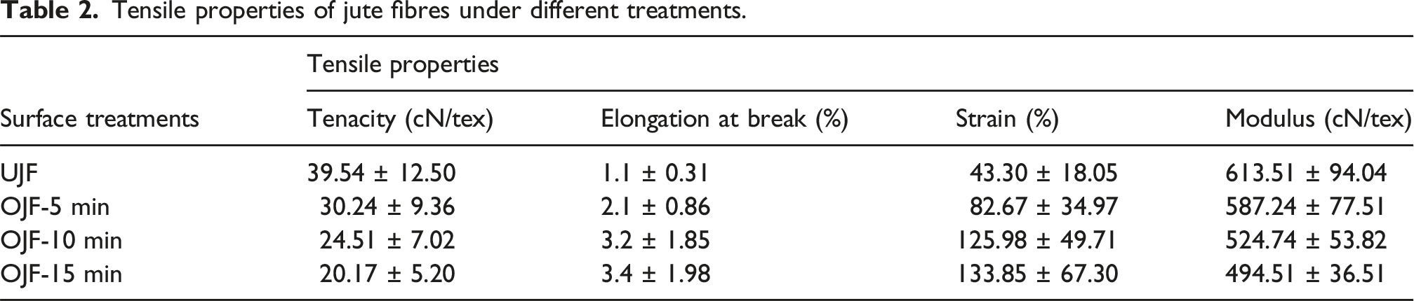
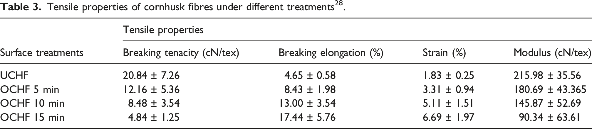
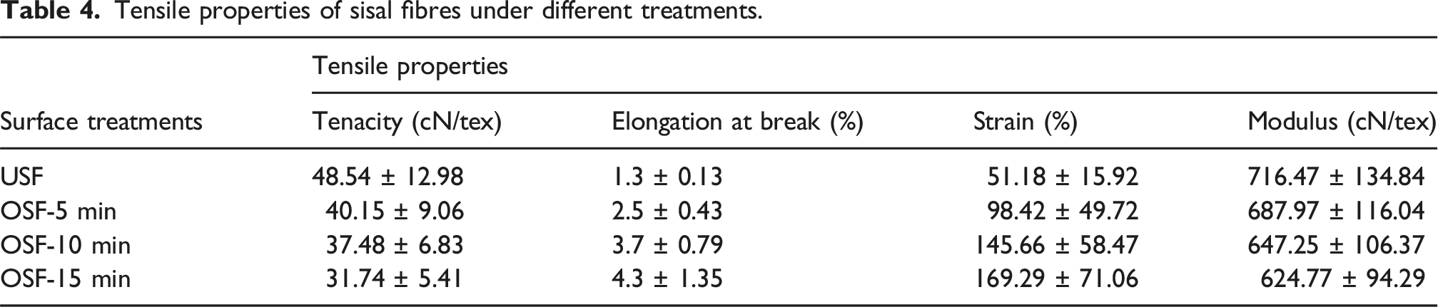
The tensile properties of untreated and ozone treated jute, cornhusk and sisal fibres are shown in Figure 7 and Tables 2–4. The maximum drop in tensile strength was seen in case of corn husk fibres followed by sisal and jute fibres after the ozone treatments. The tensile strength was reduced by 70%, 60%, and 47% in case of corn husk, sisal, and jute fibres respectively after 15 min of ozone treatment. This behaviour was attributed to the defibrillation and fibre rupture after the ozone treatment, which further reduced the load bearing capacity of bundle of fibres. For instance, the breaking tenacity of 39.54 cN/tex, 20.84 cN/tex and 48.54 cN/tex was recorded for untreated jute, corn husk and sisal fibres, respectively. However, 5 min, 10 min and 15 min ozone treated corn husk fibres indicated the breaking tenacity of 30.24 cN/tex, 24.51 cN/tex, 20.17 cN/tex for jute fibres followed by 12.16 cN/tex, 8.48 cN/tex and 4.84 cN/tex for cornhusk fibres and 40.15 cN/tex, 37.48 cN/tex and 31.47 cN/tex for sisal fibres, respectively (see Tables 2–4). The obtained results of ozone treated plant fibres in present study were further compared with previously reported findings in literature (see Tables 2–4). The loss in breaking tenacity can be explained by the fact that the fibres might have experienced molecular distortion and lacked packing density. The effect of corona treatment of plant fibres was also reported to cause reduction in tensile strength and modulus in previous works.
34
Furthermore, the breaking elongation and initial modulus was found to decrease among all the plant fibres with increase of ozone treatment time. The plant fibres were found to become brittle with the prolonged ozone treatment time, which was expected to be beneficial during pulverization in ball milling. The lower toughness values of ozone treated plant fibres can be attributed to the dissolution of amorphous region and possible changes in crystallinity. Nevertheless, a minimal drop of just 15%, 28% and 33% was observed in strain values of corn husk, jute, and sisal fibres respectively, which indicated intact crystalline structure without severe damage to cellulose macromolecules after the ozone treatment. Similar results of less than 10% differences in strain values were found in literature when the plant fibres were plasma treated.
35
Tensile properties of fibres. Tensile properties of jute fibres under different treatments. Tensile properties of cornhusk fibres under different treatments
28
. Tensile properties of sisal fibres under different treatments.
Surface microstructure of milled fibres
From the SEM images of Figures 8–10 we can further justify that ozone treatment can cause the fibres to become brittle, which is useful for milling them easily. The average diameter of the five cornhusk particles were calculated as 2.24 ± 0.25 μm for untreated, 2.05 ± 0.26 μm for ozone treated 5 min, 1.66 ± 0.27 μm for ozone treated 10 min and 0.37 ± 0.25 μm for ozone treated 15 min. Similarly, the average diameter of five jute particles were calculated 2.70 ± 0.20 μm for untreated, 1.22 ± 0.22 μm for ozone treated 5 min, 1.13 ± 0.27 μm for ozone treated 10 min and 1.00 ± 0.15 μm for ozone treated 15 min. On the other hand, the average diameter of five sisal particles were measured as 1.03 ± 0.19 μm for untreated, 0.57 ± 0.13 μm for ozone treated 5 min, 0.56 ± 0.12 μm for ozone treated 10 min and 0.54 ± 0.08 μm for ozone treated 15 min.

SEM images of the cornhusk fibres.

SEM images of the jute fibres.

SEM images of the sisal fibres.

Creep behaviour of jute fabric/epoxy composites by different models.

Creep behaviour of jute fabric/epoxy composites by different models.

Creep behaviour of jute fabric/epoxy composites by different models.
Creep behaviour of jute fabric/epoxy composites
Findley’s model
Tables 5-13 (provided in supplementary document) shows the estimated parameters of Findley’s model calculated by curve fitting as shown in Figures 11–13. The creep strain of all composites was found to increase with increase in temperature, however the effect was found higher in case of ozone treated jute composite than the particle loaded OJF composites. This can be attributed to increased Brownian motion and collision frequency, combined with the inherently high surface energy of lignocellulosic particles. As temperature rises, the reduced stabilization forces and enhanced surface mobility promote van der Waals driven coalescence, resulting in larger agglomerates.36–39 The parameter Interfacial characteristics of the cornhusk loaded composites. Interfacial characteristics of the jute loaded composites. Interfacial characteristics of the sisal loaded composites.


Burger’s model
The estimated four parameters
Coupling model
Tables 5-13 (provided in supplementary document) shows the estimated parameters of Coupling model determined by curve fitting in Figures 11–13. The parameters
Nanoindentation of jute fabric/epoxy composites
Nanoindentation results determines the hardness and elastic modulus of neat OJF + E, OJF + E + CHP1, OJF + E + CHP3, OJF + E + CHP5, OJF + E + JP1, OJF + E + JP3, OJF + E + JP5, OJF + E + SP1, OJF + E + SP3, OJF + E + SP5 composites at nano/micro scale. The hardness measurements represents the resistance of material to local surface deformation, and elastic modulus demonstrates the total stiffness of the polymer stiffness.
40
A series of five indentation were performed for each of the samples along the matrix– interphase–fibre to analyse the inhomogeneity in interfacial mechanical properties caused by spread of an interphase. The mean measurements of these five indents were chosen to evaluate the hardness and elastic modulus. Figures 14–16 demonstrated the hardness and the elastic modulus measurements for composites composed of neat OTJWF + E, OTJWF + E + CHP1, OTJWF + E + CHP3 and OTJWF + E + CHP5 plotted along the matrix–interphase fibre, respectively. In contrast to neat OTJWF composites, the OTJWF + E + CHP composites displayed typical elastic behavior. A transition region was observed between the fibre and matrix, which had indentation properties intermediate between those for the fibre and matrix. The transition region was considered as the interphase region, which was found softer close to the epoxy matrix, whereas stiffer close to the reinforcement. The image of inhomogeneity in mechanical characteristics caused due to presence of an interphase was calculated from results shown in Figures 14-16. The composites loaded with 5% fillers exhibited maximum uniformity in spread of interfacial mechanical properties followed by 1% particle incorporated composites due to their large interphase thickness. On the other hand, neat OJF + E composite revealed no clear trend in spread of interfacial properties. This behavior was attributed to the small diameter, high aspect ratio and higher surface to volume ratio of 5% particle reinforced composites, which formed a percolated network in the composites and built strong interfacial bond with polymer chains.
41
This consequently increased the load transfer sites between the matrix and reinforcement uniformly and prevented the failure due to high stress concentration.
42
In case of neat OJF + E, due to their huge mismatch in size with the polymer, they did not align as effectively as 5% filler loaded composites, which consequently reduced their interfacial bonding and micromechanical locking. Figures 17–20 showed the load-penetration depth curves and SPM images obtained after the composites are indented. The load-penetration depth behavior showed that 5% loaded composites experienced the lowest depth of indentation marks due to higher hardness and elastic modulus of the material. On the other hand, neat OJF + E and OJF + E + 1% and OJF + E + 3% particle loaded composites showed indentation marks more pronounced. This further confirmed more elastic behaviour of OTJWF/E/CHP5% composite due to their faster elastic recovery after deformation. Furthermore, from Table 4, the incorporation of CHP5% into resin was found to increase the hardness and elastic modulus of the ozone treated composites. The CHP5% loaded composites offered maximum hardness of 0.67 GPa compared to 0.57 GPa and 0.45 GPa hardness of OTJWF/E/CHP3% and OTJWF/E/CHP1% respectively. Another interesting observation could be stated that the sisal particle reinforced composites revealed better properties when compared with jute and cornhusk particle loaded composites. The reason maybe due to the increase in tensile properties of sisal fibres. Therefore, we can conclude that with the addition of 5% particles, the hardness of composite increased (Table 14). Load-penetration curves of the polymeric composites. Indentation marks for cornhusk loaded different composites. Indentation marks for jute loaded different composites. Indentation marks for sisal loaded different composites. Maximum load required to debond the jute fibre from the epoxy matrix. Nanoindentation characteristics of various composites.


Interfacial shear properties of jute fabric/epoxy composites
Interfacial shear strength of jute fabric/epoxy composites with different filler loadings.

Conclusions
We have studied the effect of ozone treatment on ball milling of natural cellulosic fibres and found the durability and creep behaviour of neat ozone treated jute fabric reinforced epoxy composite and cornhusk filler loaded composites after exposure at different temperatures. The performance of OJF + E + particle loaded samples over neat OJF + E composites were compared for improvements in thermo-mechanical, creep properties and hardness of composites. It was found that the composites loaded with 5 wt.% offered highest hardness, creep resistance and other thermomechanical properties at room temperature. But, the properties deteriorated as the temperature increased. The reason can be attributed to agglomeration of the particles leading to greater inhibition of slippage and reorientation of polymer chains with increasing contents of fillers. Therefore, ozone treatment can be an alternative chemical treatment to remove lignin and other impurities from the fibre surface. We have chosen 10 min ozone treated samples because as the treatment time reduce the strength of the fibre falls drastically leading to rupture of the fibre surface. The creep and dynamic mechanical properties of the particle loaded ozone treated jute composites were found better than the neat ozone treated jute composite. This may have happened because of the increase in mechanical interaction between the fibre/matrix due to defibrillation and rough fibre surfaces, which offered greater surface area for higher shear interfacial strength and lower creep deformation of the composite. The various creep models were used to estimate the durability of composites by validating the experimental obtained creep results. The Findley model being primitive in nature did not show very high R2 values. As the complexity of model increased to more parameters (Burger’s model), the experimental results fitted well with the models. However, Burger’s model did not describe the creep mechanism besides having many parameters. The coupling model was found suitable for explaining the creep mechanism with specific physical meaning. These models suggested that the improvements in fibre/matrix interface is very important to ensure longer life of natural fibre-based composites.
Supplemental Material
Supplemental Material - A comparative study on the creep behaviour of ozone treated jute fabric/epoxy composites filled with ozonized and pulverized plant fibres
Supplemental Material for A comparative study on the creep behaviour of ozone treated jute fabric/epoxy composites filled with ozonized and pulverized plant fibres by Debarati Bhattacharyya, Vijay Baheti, Priyanka Saini, Lakshmi Narayan Ramasubramanian in Journal of Composite Materials
Footnotes

Funding
The authors received no financial support for the research, authorship, and/or publication of this article.
Declaration of conflicting interests
The authors declare that they have no known competing financial interests or personal relationships that could have appeared to influence the work reported in this paper.
Data Availability Statement
Data will be made available on request.
Supplemental Material
Supplemental material for this article is available online.
References
Supplementary Material
Please find the following supplemental material available below.
For Open Access articles published under a Creative Commons License, all supplemental material carries the same license as the article it is associated with.
For non-Open Access articles published, all supplemental material carries a non-exclusive license, and permission requests for re-use of supplemental material or any part of supplemental material shall be sent directly to the copyright owner as specified in the copyright notice associated with the article.
