
Abstract
Carbon fiber reinforced aluminum matrix (CF/Al) composites have great potential for lightweight applications, but their interfacial wettability is poor. In order to improve CF/Al interfacial bonding, a continuous copper coating was deposited on carbon fibers via electroless plating, and the effect of copper-coated carbon fiber (Cu@CF) content on composite microstructure and properties was investigated. The results showed that increasing Cu@CF content decreases density, coefficient of thermal expansion (CTE), and thermal conductivity, while hardness and tensile strength initially increase and then decline. Optimal comprehensive performance was obtained at 1 wt.% Cu@CF, achieving a tensile strength of 281.91 MPa, a friction coefficient of 0.7912, and a wear rate of 2.79 × 10⁻² mm3/N·m. Previous studies have primarily focused on enhancing wettability or suppressing interfacial reactions using ZnO, Ni, or Al2O3 coatings, but the influence of coated-CF content has rarely been investigated. By revealing how Cu@CF content regulates Al2Cu formation and interfacial compatibility, a clear composition-structure-property relationship is established, providing practical guidance for designing high-performance lightweight Al-based composites.
Keywords
Introduction
Aluminum (Al) and its alloys are essential lightweight structural materials for various applications, particularly transportation and armament.1–5 Al-based alloys and composites have been widely adopted in aerospace structures, automotive engine components, and electronic thermal-management devices owing to their low density, high specific strength, and good thermal conductivity.6–8 However, due to their insufficient wear resistance and ductility, these materials are not suitable for demanding service conditions.9,10 Although aluminum matrix composites typically exhibit enhanced strength and hardness, as well as significantly improved wear resistance and reduced friction, the resulting decline in ductility remains a key challenge, emphasizing the importance of interfacial design in achieving balanced tribo-mechanical properties. 11 Traditionally, ceramic materials such as Al2O3, SiC, TiB2, and TiC12–15 are frequently incorporated into Al matrix composites to improve strength and modulus. However, large ceramic particles can lead to significant abrasive wear because of their elevated hardness, whereas nano-scale ceramic particles’ dispersion and surface modification present significant technical difficulties.16,17 Although ceramic reinforcements effectively improve stiffness and wear resistance, their intrinsic brittleness and interfacial incompatibility may reduce the toughness and reliability of Al-based composites. 8
Recently, carbon-based materials, such as carbon fibers, 18 carbon nanotubes, 19 and graphene, 20 have been extensively utilized as effective reinforcements to improve Al matrix composites. Carbon-based reinforcements offer a more balanced improvement in stiffness, toughness, and tribological behavior than hard ceramics, further supporting their growing prevalence in advanced Al composites.6,7 Among them, carbon fibers have drawn more attention as a crucial reinforcement for Al matrix composites due to their high elastic modulus, low density, exceptional strength, and low coefficient of thermal expansion.21–23 Carbon fiber reinforced aluminum matrix (CF/Al) composites combine the superior features of both materials and are regarded as advanced lightweight materials for civil and military applications.24–26 Nonetheless, there are several major issues with the production of CF/Al composites. Firstly, the development of CF/Al composites is hindered by the inadequate wettability between the CF and the Al matrix, making it difficult for the molten aluminum to effectively infiltrate the carbon fiber bundles.27–29 Second, a brittle aluminum carbide (Al4C3) phase may emerge as a result of a substantial interfacial corrosion reaction between the CF and matrix during high-temperature preparation conditions.30,31 The excessively strong interfacial bonding between the carbon fiber and matrix, caused by interfacial reactions and the formation of the brittle Al4C3 phase, may affect the characteristics of CF/Al composites. 32 Therefore, previous studies have emphasized the importance of improving interfacial compatibility while suppressing detrimental reactions for achieving stable mechanical and tribological performance.33–35 A successful approach involves treating the surface of carbon fibers to enhance wettability and mitigate interfacial interactions between the CF and matrix.
Several studies have been conducted on the carbon fiber coating technique. Carbon fibers are typically coated with ceramic or metallic materials to improve aluminum matrix composites. For instance, Zhu et al. 36 modified carbon fibers with a ZnO coating in order to enhance the characteristics of Al matrix composites. A significant improvement in mechanical characteristics was attained by suppressing the interfacial interaction between the CF and the Al, resulting in a modulus of 105.3 GPa and a flexural strength of 796.4 MPa. Hajjari et al. 37 examined the influence of a nickel coating on the mechanical characteristics of CF/Al composites. The findings indicated that the nickel coating significantly enhanced the mechanical properties by enhancing wettability and inhibiting reactions between the CF and molten Al, thereby achieving a tensile strength of 492 MPa. In addition to metallic coatings, carbon fibers coated with ceramic coatings can also be used to prepare Al matrix composites. Zhu et al. 38 deposited an Al2O3 coating on carbon fibers via the sol-gel method. By enhancing the wettability between the CF and the Al matrix, the mechanical properties of the resulting composite were significantly improved. Although both ceramic and metallic coatings improve wettability and prevent the severe interfacial interaction between the CF and Al matrix, ceramic coatings incur higher manufacturing costs and exhibit greater susceptibility to cracking and peeling.39,40
In summary, several studies have utilized carbon fibers as a reinforcement phase to enhance the properties of aluminum matrix composites, and employed coating deposition to enhance the wettability between the CF and the matrix, with the majority of them focusing on wettability and interfacial reactions after surface treatment. However, only a few studies have examined how the amount of coated carbon fibers influences interfacial bonding, microstructural evolution, and resulting mechanical and tribological performance, leaving a clear research gap. In this study, a copper coating is deposited on carbon fibers via an electroless plating process. The prepared copper-coated carbon fibers (Cu@CF) are then consolidated via spark plasma sintering (SPS) to fabricate the copper-coated carbon fiber reinforced aluminum matrix (Cu@CF/Al) composite. The aim of this work is to determine the effect of Cu@CF content on composite structure and properties by combining microstructural analysis with mechanical, thermal, and tribological evaluation tests. The influence of Cu@CF content on the microstructure and enhanced properties of the composites is thoroughly investigated and a clearer composition-structure-property relationship is established for optimizing interfacial engineering in Al-based composites.
Experimental
Raw materials
Spherical aluminum powder (purity >99.7 wt.%) from Beijing Yijin New Material Technology Co., Ltd and carbon fiber from Weihai Guangfu Composite Materials Co., Ltd were utilized in the fabrication of Cu@CF/Al composites. Figure 1 displays the scanning electron microscopy (SEM) images and an X-ray diffraction (XRD) pattern of aluminum powder. As shown in Figure 1(a), the Al powder has a highly spherical morphology with a narrow particle-size distribution and smooth surfaces, indicating good flowability and packing behavior during consolidation. The absence of sharp edges or severe agglomeration helps to reduce local stress concentration and promotes uniform densification during spark plasma sintering (SPS). Figure 1(b) further confirms the high purity of the raw Al powder, as only characteristic diffraction peaks of metallic Al are detected without any oxide-related phases. Such high purity and spherical geometry provide favorable conditions for achieving stable interfacial bonding, controlled interfacial reactions, and reliable mechanical performance in the final Cu@CF/Al composites. (a) SEM morphology of spherical Al powder, and (b) corresponding XRD pattern confirming its phase composition.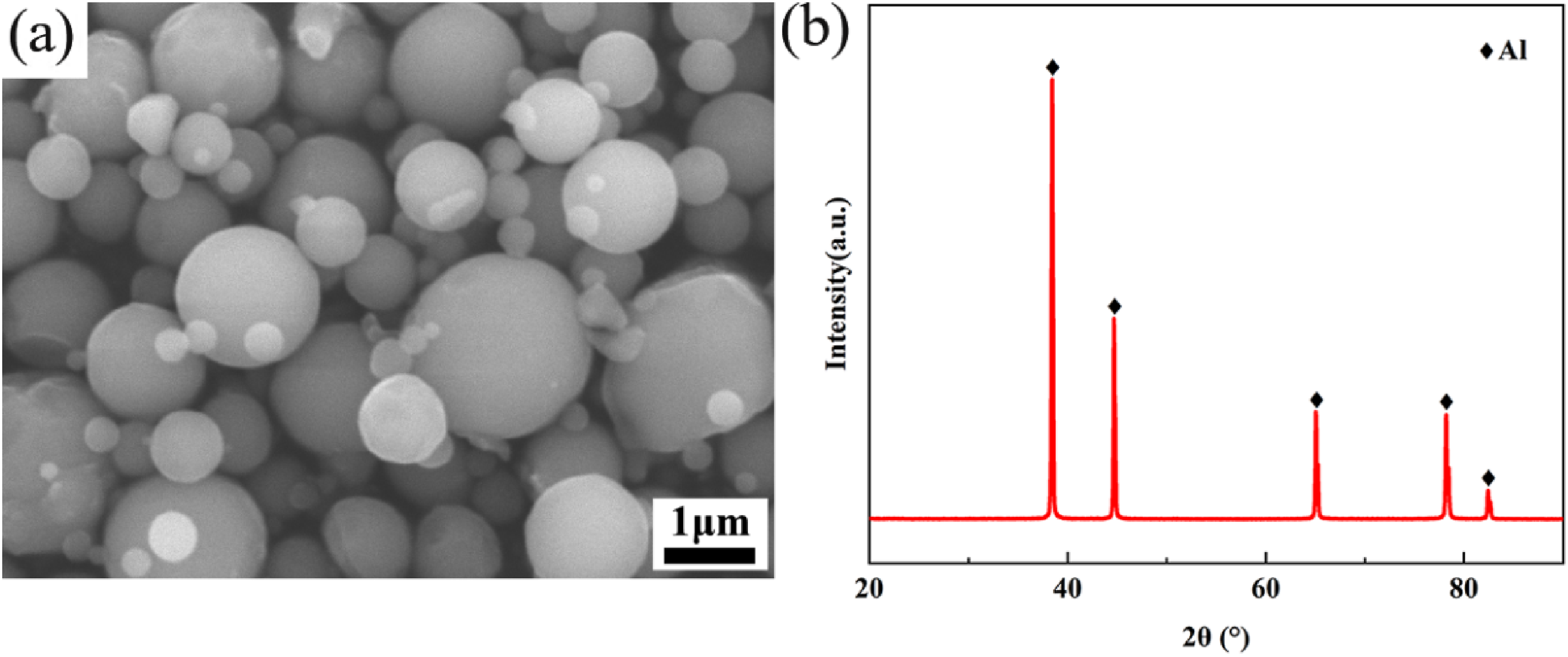
Deposition of Cu coating on the surface of carbon fiber
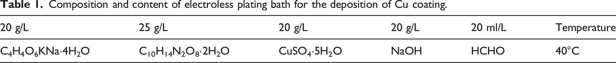
Composition and content of electroless plating bath for the deposition of Cu coating.
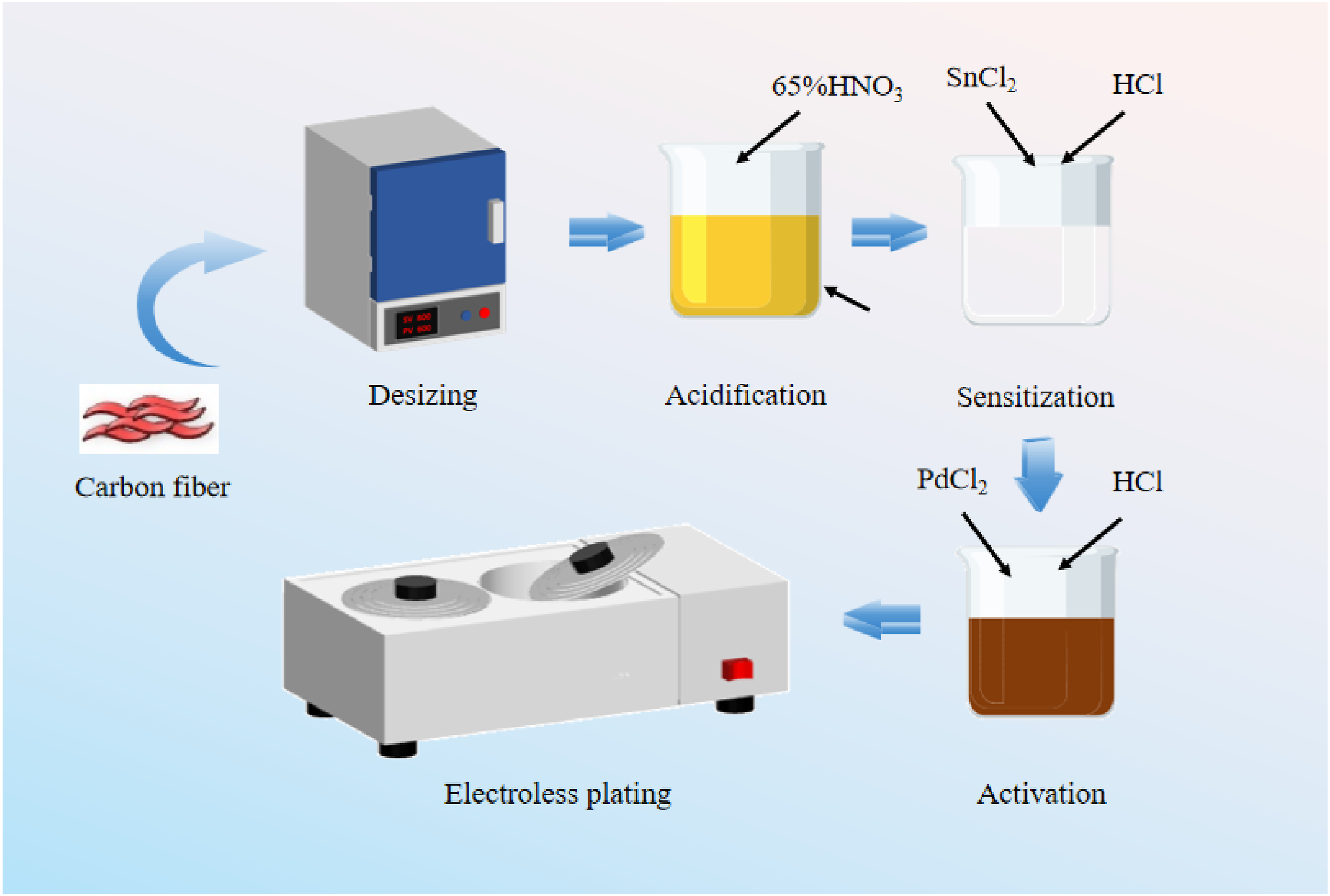
Fabrication procedure of Cu@CF.
Fabrication of Cu@CF/Al composites
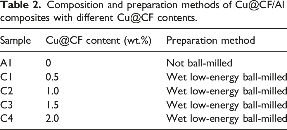
Composition and preparation methods of Cu@CF/Al composites with different Cu@CF contents.
The mixtures were then cold compressed utilizing a plate vulcanizer (XLB, Yadong, China) at a pressure of 25 MPa to form a specimen. Cold compaction at this moderate pressure ensures sufficient green-body integrity while preventing premature damage to the carbon fibers or the Cu coating. The specimen was sintered in a spark plasma sintering furnace (SPS-625, Sumitomo, Japan) using the sintering parameters shown in Figure 3. The SPS method was selected because of its rapid heating rate and localized Joule heating, which suppresses undesirable interfacial reactions (such as excessive formation of brittle Al4C3) while facilitating controlled generation of beneficial Al2Cu phases. These advantages allow the formation of a dense microstructure with strong interfacial bonding and low grain coarsening. Sintering temperature-pressure profile used for the fabrication of Cu@CF/Al composites.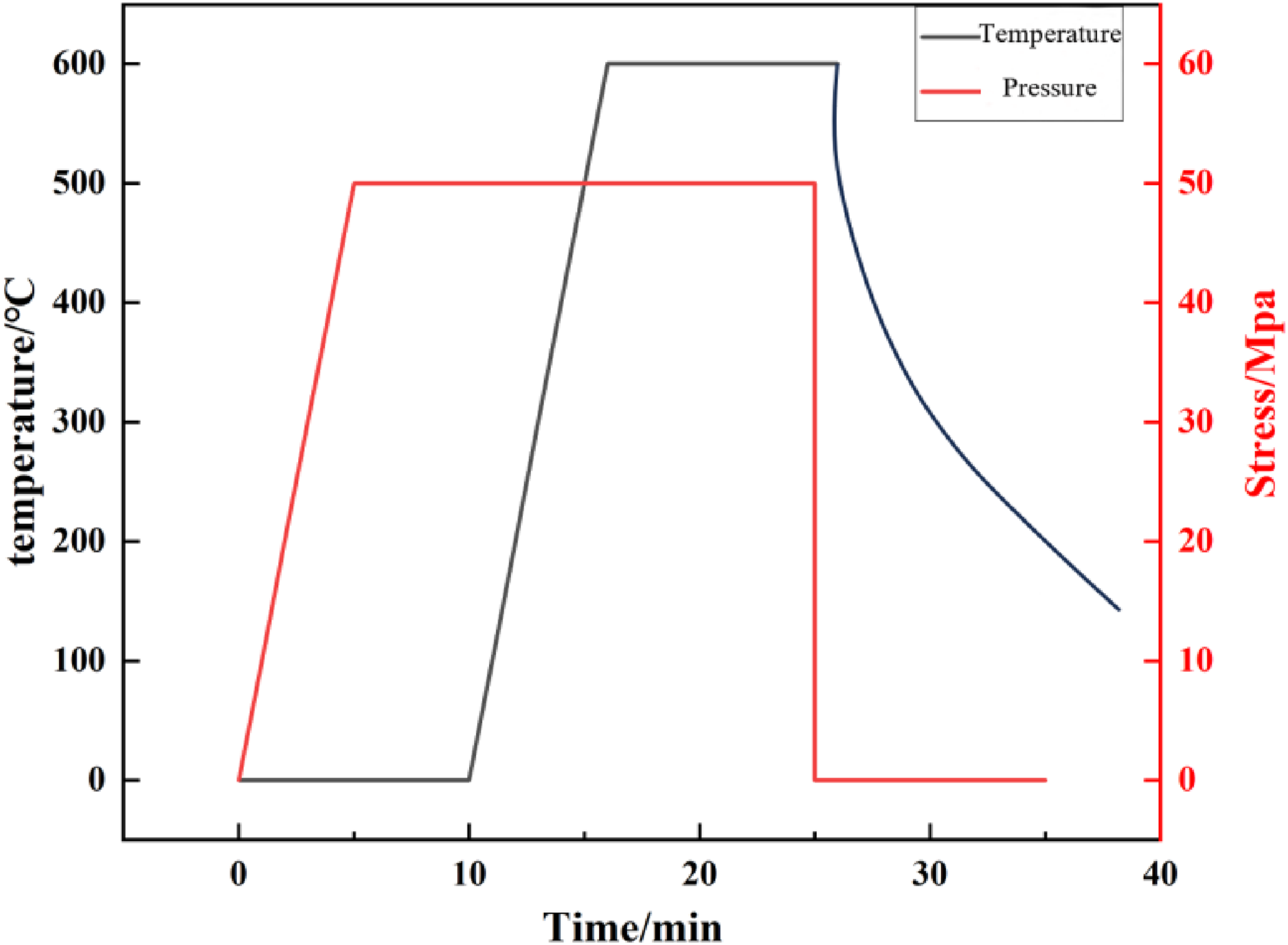
Characterization
The coefficients of thermal expansion and thermal conductivity of the composites were determined using a thermal dilatometer (DIL 402, Netzsch, Germany) and a thermal conductivity meter (LFA 467, Netzsch, Germany), respectively. The standard operating procedures (SOPs) of the instruments were followed to ensure data repeatability and reliability. The precise density of the composites was determined utilizing a density meter (Ultrapyc3000, Anton Paar, China) that used the gas displacement method and was calibrated and tested according to the instrument’s operating specifications. The distribution of elements and the microstructure of the composites were examined through a scanning electron microscope (SEM, 4500 S, Hitachi, Japan), which is equipped with energy dispersive spectroscopy (EDS). The phase components were identified through X-ray diffraction (XRD, D8, Bruker, Germany), with scanning parameters set according to standard diffraction analysis methods for materials.
The hardness was measured using a Brinell hardness tester (310HBS-3000, Huayin, China) with a 500 N load applied for 15 s. Hardness tests were performed at six different locations for each sample, and the average value was recorded. The tensile strength was determined using a universal testing machine (34FM-100, Instron, USA) at a strain rate of 0.5 mm/min under ambient temperature conditions. Tensile testing was performed in accordance with the standard procedures for metallic materials, and the fracture surface was analyzed by SEM after testing.
The friction coefficient was determined using a multi-functional friction and wear tester (MFT-5000, Rtec-Instruments, USA). A GCr15 steel ball (60 HRC) with a diameter of 6.35 mm was used as the relative friction material. The reciprocating sliding method was used as the experimental mode. Before the experiment, the sample surface was polished with a 0.25 μm alumina colloidal suspension containing a polishing agent. The applied loads were 10 N, the frequency of friction was set at 1 Hz (0.01 m/s), and the sliding distance (stroke) was 5 mm. These conditions are similar to the reciprocating friction conditions of small, lightweight components under moderate contact pressure in real-world engineering applications, such as small gear pairs, miniature sliding bearings, connectors, and guiding structures. The laser confocal microscope (LSM-700, Zeiss, Germany) was used to acquire the 3D profile and the cross-section curve of the worn surface. The wear loss was measured by comparing the weight of the pins before and after the test. The wear rate was measured by calculating the wear loss in relation to the sliding distance. The wear surface morphology of the composites was examined using the SEM after the friction test.
Results and discussion
Effect of Cu@CF content on microstructure of Cu@CF/Al composites
Figure 4 shows the microstructure of carbon fibers, with Figure 4(a) presenting the SEM image of original carbon fibers, and Figure 4(b) depicting the surface morphology after pretreatment. After pretreatment, the originally smooth carbon-fiber surface developed distinct groove-like textures, significantly increasing the effective surface area and creating additional mechanical anchoring sites for subsequent metal deposition. Such micro-texturing improves coating adhesion and interfacial compatibility with the aluminum matrix. The SEM image of the Cu@CF is shown in Figure 4(c), where the surface was covered by a dense coating composed of uniformly distributed fine grains. The granular coating morphology suggests that the electroless plating process enabled homogeneous nucleation and growth of Cu particles, forming a continuous protective shell around the fiber. Figure 4(d) shows the EDS elemental mapping of a specific Cu@CF region. The Cu was uniformly distributed on the fiber surface, while no detectable C was present, indicating the successful formation of a fully enclosed metallic layer without exposing the underlying carbon fiber, confirming both the uniformity and completeness of the Cu coating. SEM images of carbon fibers: (a) original CF, (b) pre-treated CF, (c) Cu@CF, and (d) Cu elemental mapping of Cu@CF.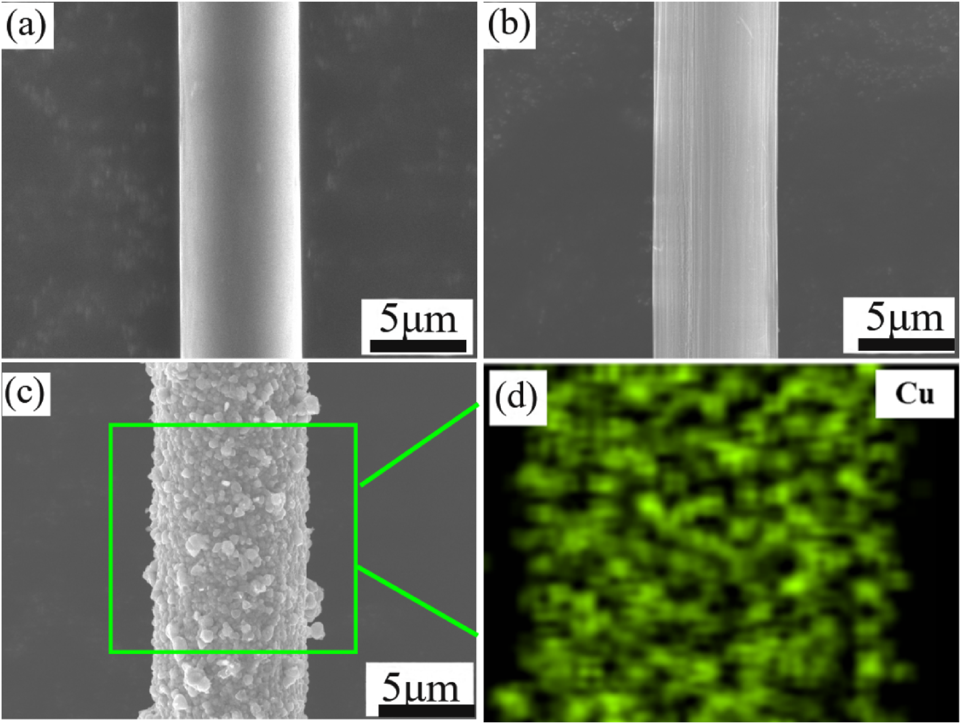
Figure 5 presents the microstructures of the pure Al matrix and Cu@CF/Al composites with different Cu@CF contents. As shown in Figure 5(a)–(b), the pure Al matrix exhibits a dense and uniform microstructure with no reinforcing phase, providing a reliable baseline for comparison. When a small amount of Cu@CF (0.5 wt.% and 1.0 wt.%) is introduced, as illustrated in Figure 5(c)–(f), the carbon fibers are uniformly dispersed within the aluminum matrix without noticeable agglomeration. This uniform distribution facilitates effective load transfer and stable interfacial bonding. However, as the Cu@CF content increases to 1.5 wt.% and 2.0 wt.% (Figure 5(g)–(j)), distinct fiber agglomeration and localized clustering emerge (marked by blue boxes in the figures). These agglomerated regions can induce stress concentrations during deformation, promote the formation and propagation of microcracks, and consequently reduce the strength and toughness of the composites.
41
In addition, fiber clustering compromises the continuity of the fiber–matrix interface, resulting in decreased interfacial bonding strength and lower overall reinforcement efficiency. These observations reveal a clear evolution of microstructure with increasing reinforcement content: low Cu@CF levels ensure uniform dispersion and effective strengthening, whereas high Cu@CF levels lead to fiber agglomeration, inevitably impairing the composite’s mechanical and tribological performance. SEM images of pure Al matrix and Cu@CF/Al composites with different Cu@CF contents: (a and b) pure Al matrix; (c and d) 0.5 wt.% Cu@CF; (e and f) 1.0 wt.% Cu@CF; (g and h) 1.5 wt.% Cu@CF; and (i and j) 2.0 wt.% Cu@CF.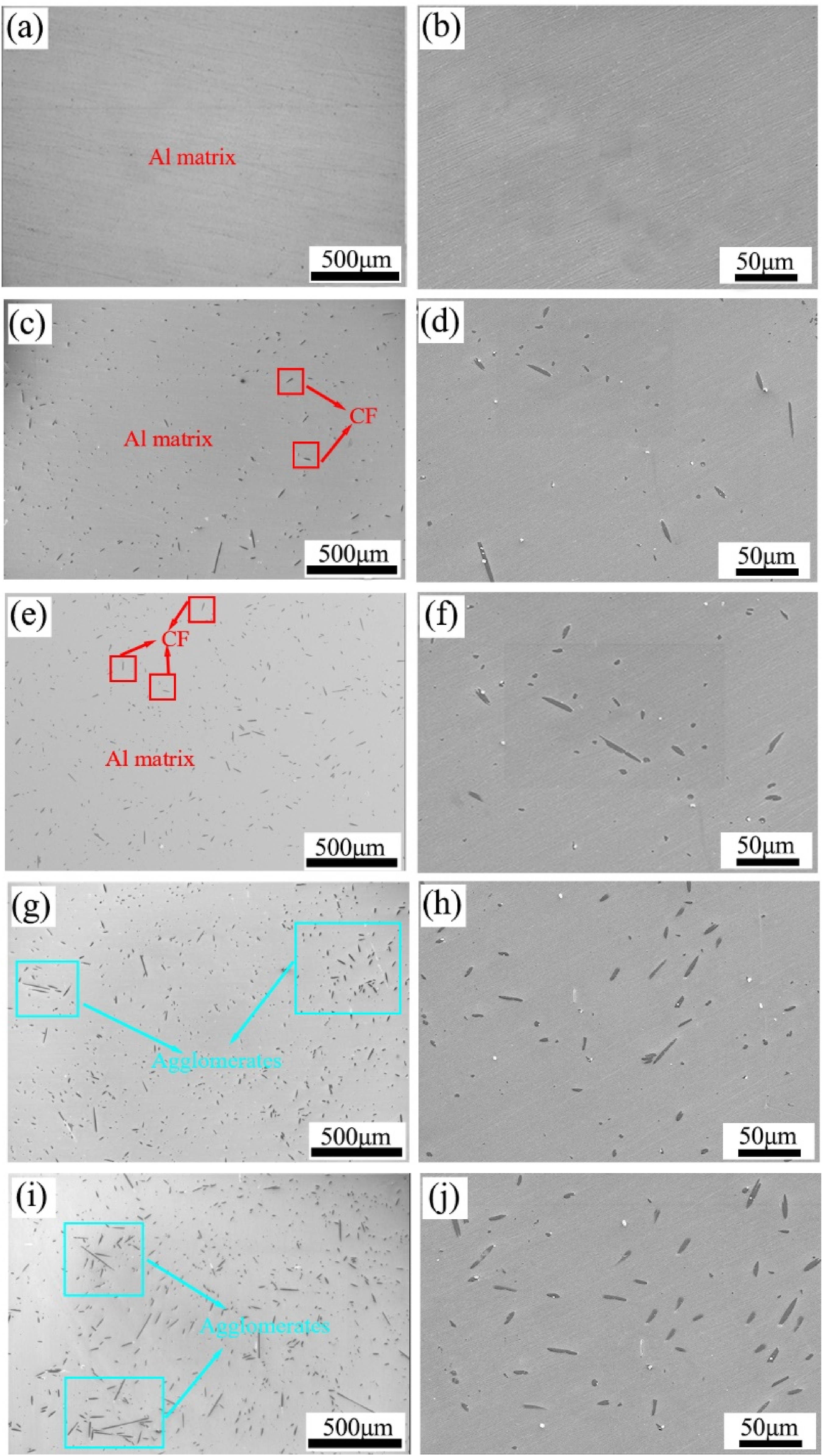
Figure 6 displays the SEM image and corresponding EDS elemental analysis of the Cu@CF/Al with a Cu@CF content of 1.0 wt.%. Figure 6(a) illustrates that the interface between the carbon fiber and the Al remains is intact and exhibits a strong bond, with no pores or gaps in the interfacial region. The continuous and compact interfacial contact demonstrates that the Cu coating significantly enhanced the wettability and mitigated the intrinsic incompatibility between carbon fibers and the aluminum matrix. According to the EDS analysis shown in Figure 6(b)–(d), Cu has diffused into the aluminum matrix. This limited but detectable Cu diffusion can be ascribed to the high diffusion coefficient of Cu in Al at elevated temperatures, enabling partial penetration into the matrix during SPS. Notably, such diffusion promotes metallurgical bonding while avoiding excessive interfacial reactions. To further analyze the interfacial bonding state, elemental line distribution (Figure 6(e)) was performed across the interfacial region. The elemental line scanning results reveal no significant elemental interdiffusion at the interface, confirming that the Cu coating acted as an effective diffusion barrier, preventing direct CF-Al contact and suppressing the formation of brittle interfacial compounds like Al4C3. This demonstrates that the coated interface is chemically stable and mechanically reliable under SPS conditions. SEM image and EDS elemental analysis of Cu@CF/Al composite: (a) microstructure of the Cu@CF/Al composite, (b–d) elemental mapping corresponding to the region in (a), and (e) line distribution across the region marked in (a).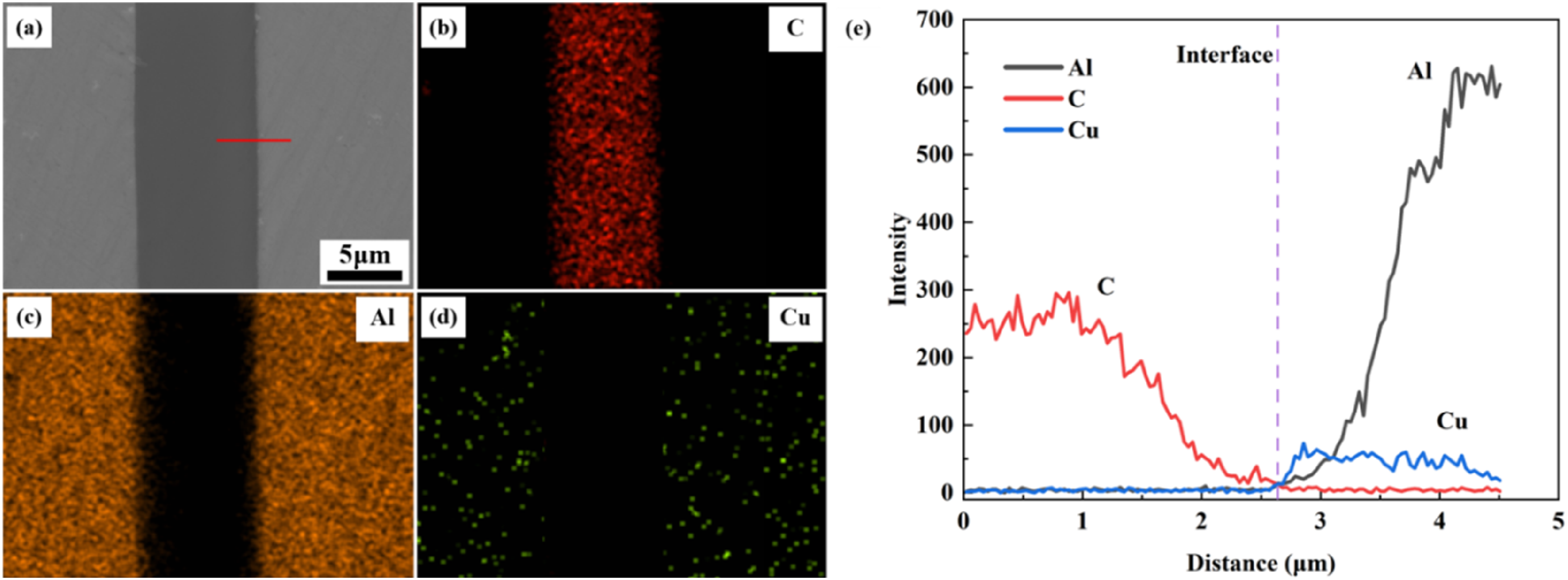
Figure 7 presents XRD patterns of Cu@CF/Al composites with different Cu@CF contents. It can be seen from the figure that all four composites exhibited characteristic diffraction peaks of Al and Al2Cu. Acting as a strengthening phase in the matrix, the Al2Cu improved strength and hardness of the matrix, which resulted in the superior resistance to deformation when the material was subjected to external stress.
42
However, distinct diffraction peaks of the Al2Cu phase became clearly observable only when the Cu@CF content reached 1.5 wt.% or higher. On the one hand, copper elements primarily accumulated on the CF surface, forming localized high-concentration regions at the fiber/matrix interface, and a higher Cu content was necessary to promote the precipitation of more Al2Cu phase. On the other hand, XRD has limited detection sensitivity for trace amounts of the Al2Cu phase, and distinct diffraction peaks in the patterns could only be observed when its content exceeded the detection threshold. Furthermore, no diffraction peaks corresponding to Al4C3 were detected in the XRD patterns with increasing Cu@CF content, and this indicated that the interfacial reaction between the CF and the Al was effectively suppressed. The presence of Al4C3 weakened the interfacial bonding strength, resulting in accelerated crack propagation along the interface.
43
XRD patterns of the Cu@CF/Al composites with different Cu@CF contents.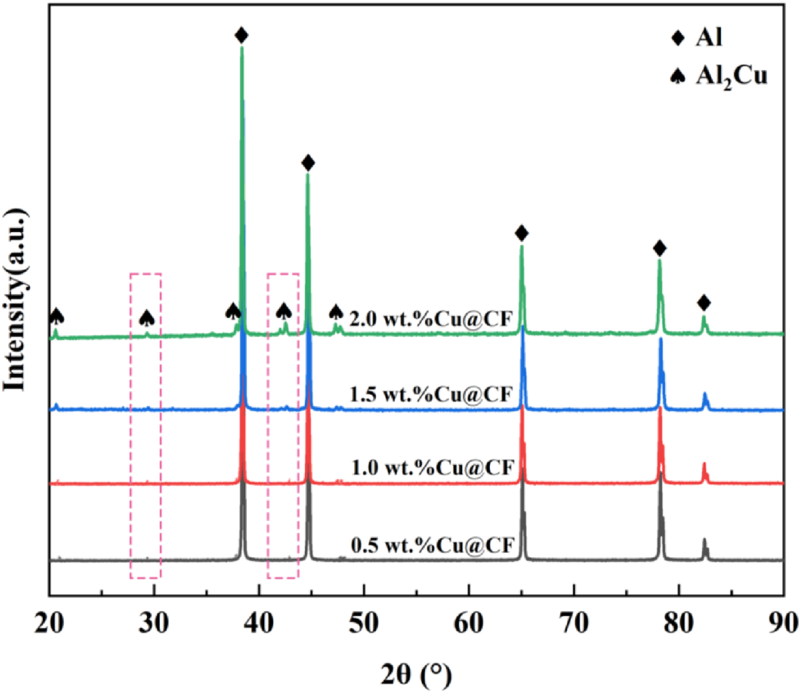
Effect of Cu@CF content on physical properties of Cu@CF/Al composites
Theoretical, measured (5 repeated tests), and relative densities of Cu@CF/Al composites with different Cu@CF contents.
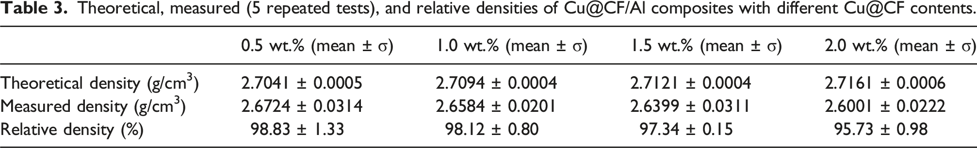
Figure 8 illustrates the coefficient of thermal expansion (CTE) curves of Cu@CF/Al with varying Cu@CF contents. The CTE of the composites decreased with increasing Cu@CF content. The carbon fibers served as a reinforcement phase with a low CTE, resulting in a significantly lower CTE compared to the matrix. Additionally, the copper reacted with the Al matrix to form an Al2Cu phase at the interface, with a CTE intermediate between the Al matrix and the CF. The formation of the Al2Cu phase not only improved interfacial bonding but also helped to mitigate the thermal expansion mismatch between the CF and the Al, increasing thermal stability of the composite.
44
Moreover, the increasing amount of Cu@CF exacerbated this dual effect: the low-expansion CF network progressively dominated the thermal response, while the interfacial Al2Cu layer acted as an effective transition zone, reducing thermal strain concentration and overall CTE. Thermal expansion curves (a and b) of the Cu@CF/Al composites with different Cu@CF contents.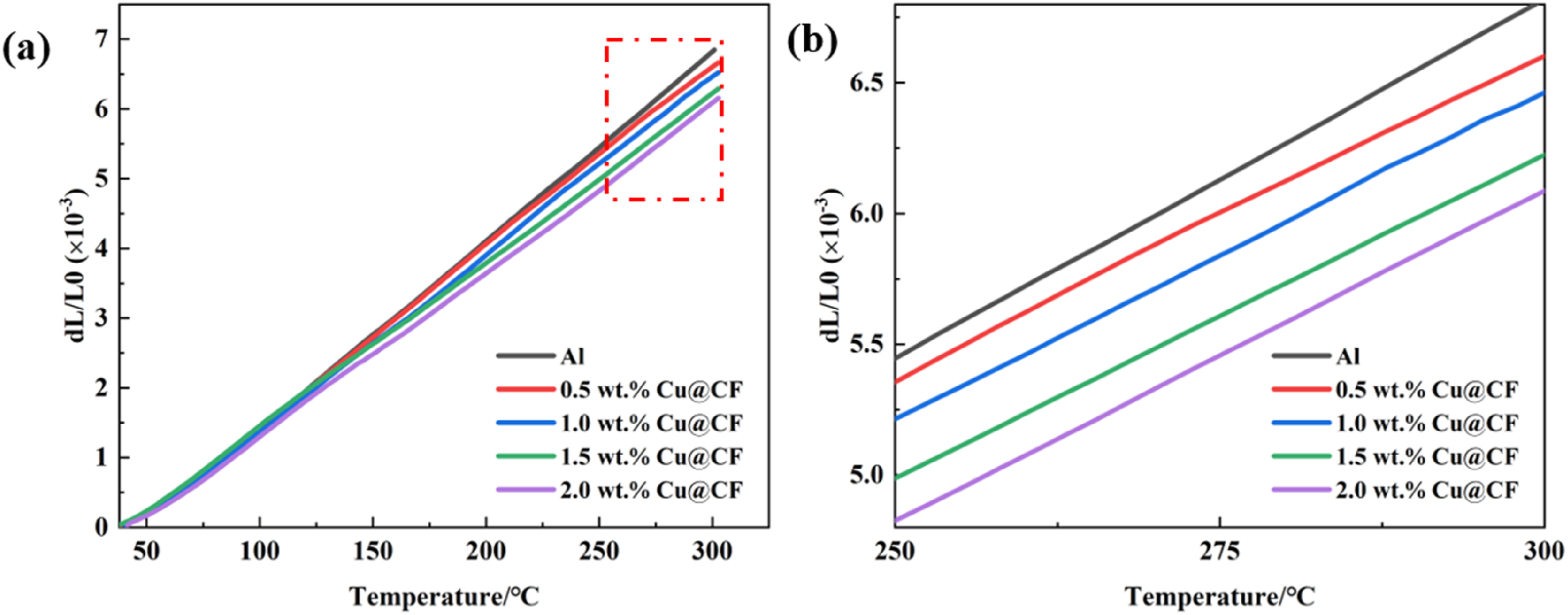
Figure 9 illustrates the thermal conductivity of the composites with different Cu@CF contents. It can be seen from the figure that the thermal conductivity gradually decreased with increasing Cu@CF content. At a Cu@CF content of 1.0 wt.%, the composite achieved a thermal conductivity that was 92.5% of pure Al, indicating a marginal decrease. In contrast, at 2.0 wt.% Cu@CF, the thermal conductivity dropped significantly to 73.3% of that of pure Al. Pure Al possessed a high intrinsic thermal conductivity, typically around 237 W/(m·K). The carbon fibers, while exhibiting an axial thermal conductivity ranging from 400 to 700 W/(m·K), demonstrated a much lower radial thermal conductivity of only 8–12 W/(m·K), indicating significant anisotropic behavior. Furthermore, interfacial thermal resistance was present between the CF and the Al in the composite, which impaired the heat transfer efficiency. Although the copper coating helped improve the interfacial bonding and reduced the thermal resistance to some extent, and copper itself possesses a high thermal conductivity (401 W/(m·K)) superior to that of Al, the relatively thin coating limited its contribution to the overall thermal conductivity. Consequently, the reduction in interfacial thermal resistance was offset by the increased thermal resistance attributed to the fiber-matrix interactions. Particularly at a Cu@CF content of 2.0 wt.%, the mutual contact and uneven distribution of the fibers likely induced local aggregation and disordered alignment. This not only increased the number of interfaces but also made the cumulative effect of interfacial thermal resistance more pronounced, which led to a sharp increase in the overall thermal resistance along the heat transfer path and significantly degraded the composites final thermal conductivity.
45
Thermal conductivity of the Cu@CF/Al composites with different Cu@CF contents.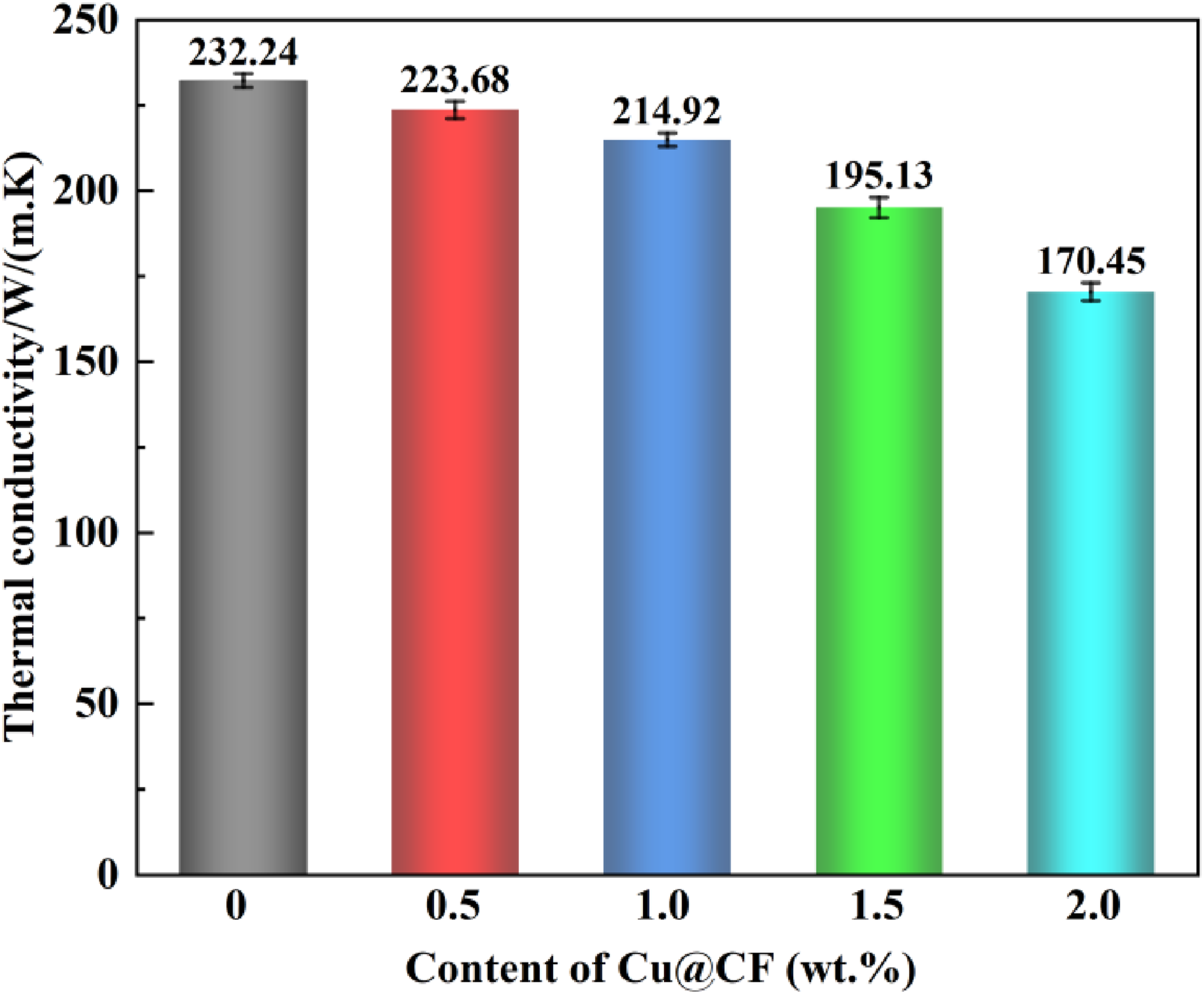
Effect of Cu@CF content on mechanical properties of Cu@CF/Al composites
Figure 10 illustrates the Brinell hardness of Cu@CF/Al composites with varying Cu@CF concentrations. The hardness initially increased and then decreased as the Cu@CF content increased. This trend can be attributed to the copper coating, which increased wettability, strengthened interfacial bonding, and prevented the formation of the brittle Al4C3 compound during high-temperature sintering. When the Cu@CF content increased to 1.5 wt.%, the Brinell hardness began to decrease, which was ascribed to carbon fiber agglomeration in the matrix (Figure 5(g)–(j)). The agglomerated CF regions led to structural discontinuities and even local defects within the composite, negatively affecting the load transfer. Brinell hardness of the Cu@CF/Al composites with different Cu@CF contents.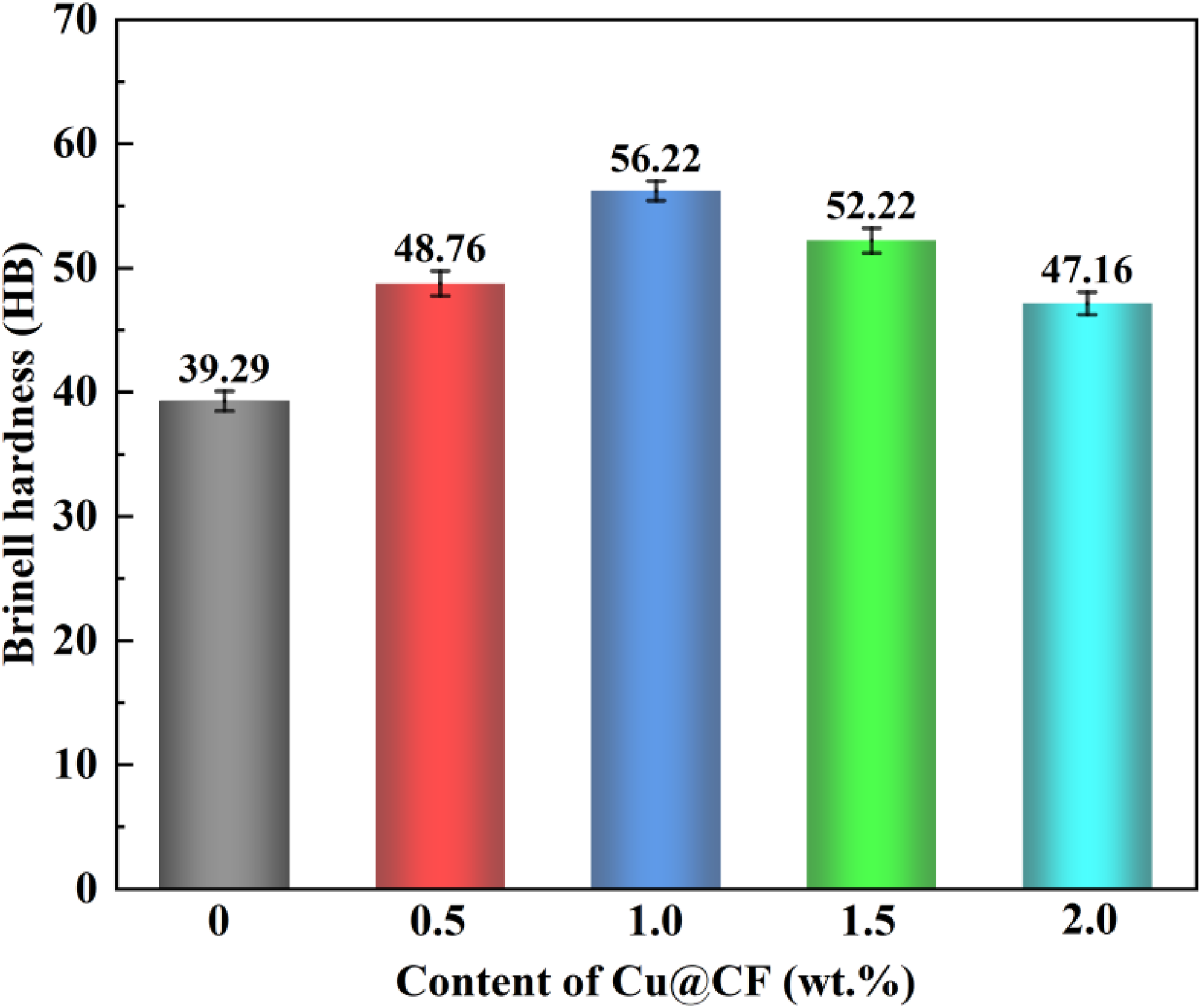
Figure 11 illustrates the tensile curves of Cu@CF/Al at various Cu@CF concentrations. When the Cu@CF content was increased, the tensile strength and yield strength of the composites first increased and then decreased. At a Cu@CF content of 1 wt.%, the composite achieved its maximum tensile strength of 281.91 MPa. This enhancement is attributed to the superior interfacial bonding provided by the copper coating, which facilitated efficient load transfer through the carbon fibers. In addition, the uniform dispersion of Cu@CF at this content resulted in the formation of a continuous reinforcing network, which further optimized stress distribution within the matrix and delayed crack initiation. However, as the Cu@CF content reached 1.5 wt.%, the tensile strength of the composite decreased. This reduction occurred because the higher carbon fiber content caused agglomeration within the matrix, increasing internal defects and consequently a decreased tensile strength of the composite. Such agglomeration not only created local stress concentration zones but also disrupted the integrity of the Al matrix, accelerating early failure under tensile loading. The elongation of the composite progressively diminished as the Cu@CF content increased. This decline occurred because the incorporation of carbon fibers enhanced material stiffness and strength while reducing its plastic deformation capacity.
46
At higher carbon fiber contents, the natural high stiffness of the fibers restricted the plastic flow of the matrix, leading to a notable decline in ductility. Moreover, the reduced interfacial continuity at higher reinforcement contents further restricted matrix deformation, amplifying the overall elongation loss. (a) Stress-strain curves and (b) variation of tensile properties of Cu@CF/Al composites with different Cu@CF contents.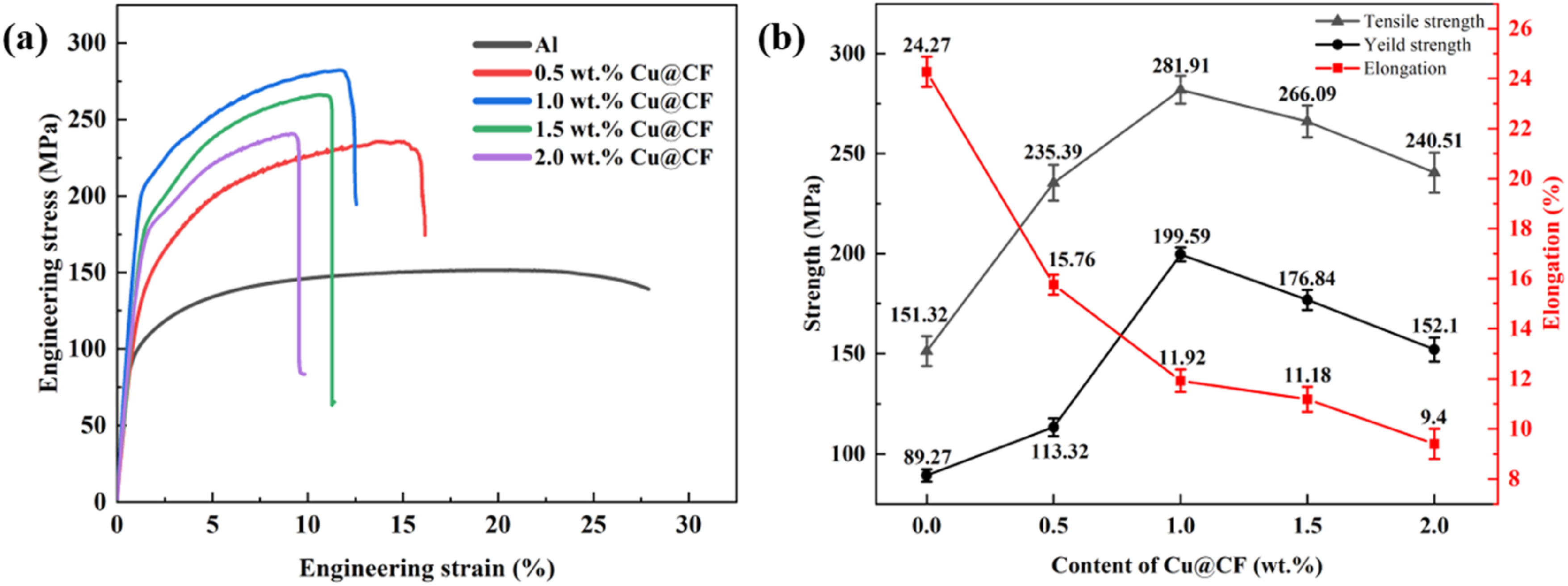
Figure 12 presents the fracture images of the Cu@CF/Al composites with different Cu@CF contents after tensile testing. As visible in Figure 12(a)–(b), at Cu@CF contents ≤1.0 wt.%, carbon fibers were uniformly dispersed in the Al matrix, and the overall fracture surface was relatively flat without significant interfacial debonding or pore defects. The dominant fracture mode under these conditions was fiber fracture, suggesting strong interfacial bonding strength. However, when the Cu@CF content increased to 1.5 wt.%, the fracture surface exhibited fiber bridging between adjacent carbon fibers, distinct interfacial debonding at the fiber-matrix interface, and localized regions with irregular characteristics (Figure 12(c)). When the Cu@CF content was 2.0 wt.%, extensive agglomeration of carbon fibers forming large aggregation zones was clearly observed in the fracture morphology (Figure 12(d)). This agglomeration effect tended to induce local stress concentration during loading, weakened the overall interfacial bonding, and consequently reduced the fracture toughness and strength of the composite. Li et al.
47
investigated the impact of CF distribution on fracture behavior of CF/Al composites. Their findings demonstrated that when the CF distribution changed from uniform to partially clustered, the fracture behavior transitioned from single fiber pull-out to bundle pull-out. Compared to uniformly distributed fibers, the non-uniform distribution and defects within fiber clusters reduced the composite performance by approximately 10%. Fracture morphology of Cu@CF/Al composites with different Cu@CF contents: (a) 0.5 wt.%, (b) 1.0 wt.%, (c) 1.5 wt.%, and (d) 2.0 wt.%.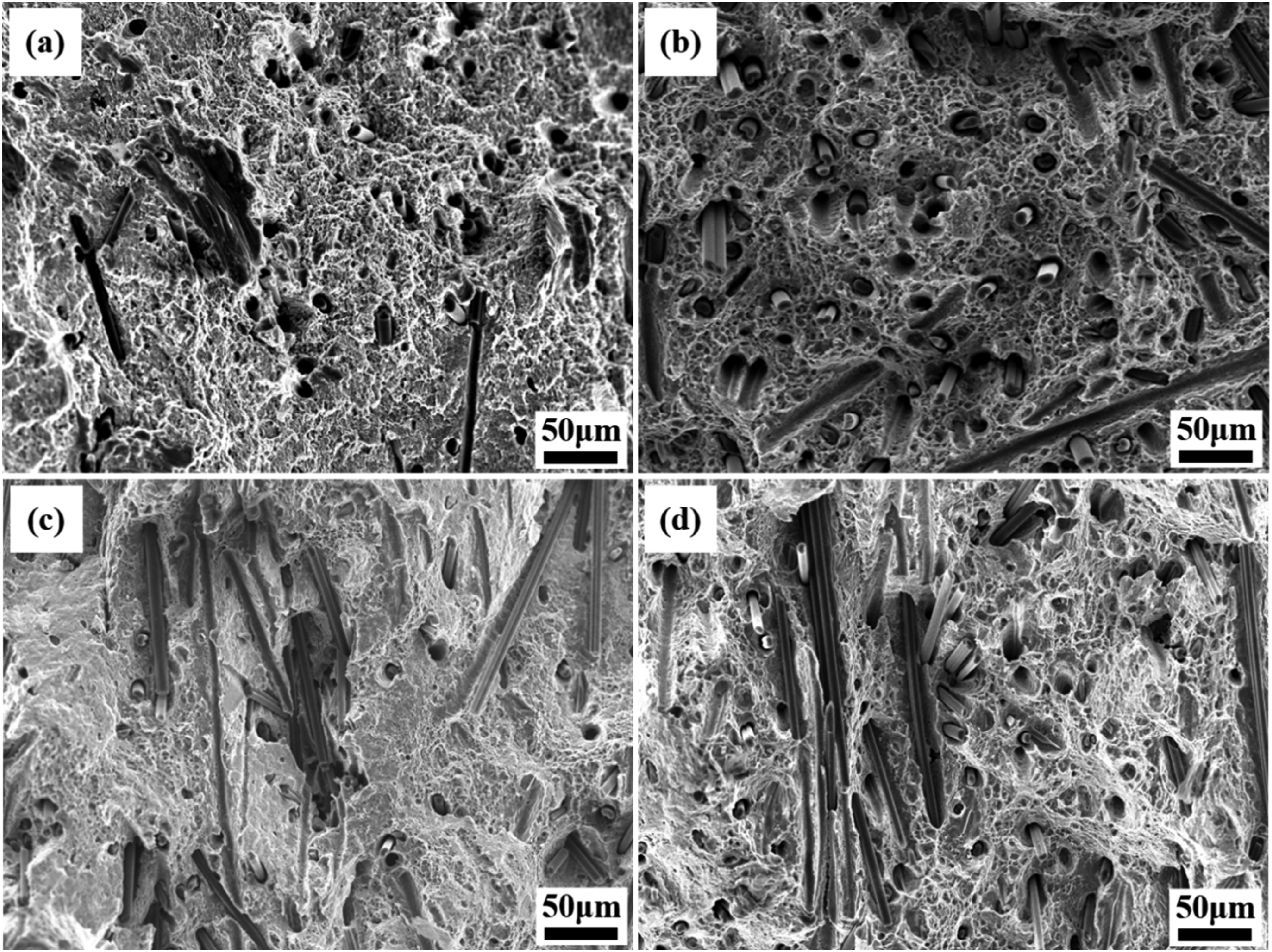
Effect of Cu@CF content on tribological properties of Cu@CF/Al composites
Figure 13 illustrates friction coefficient curves and average friction coefficient for Cu@CF/Al composites with varying Cu@CF contents. The friction coefficient of the composite first decreased and then increased with increasing Cu@CF content. For pure Al, it not only showed a higher friction coefficient but also exhibited significant fluctuations in the friction curve. This was primarily attributed to the low hardness and poor wear resistance of the aluminum matrix itself, which made it prone to adhesive wear during contact with the counter steel ball.
48
When local adhesion and tearing occurred on the surface, the friction force suddenly increased or decreased, consequently leading to sharp oscillations in the friction curve. In contrast, the CF had a lower friction coefficient, and its graphitic structure provided excellent self-lubricating properties, thereby creating a friction-reducing effect.
49
Furthermore, the Cu@CF exhibited improved interfacial wettability with the Al matrix. The interfacial reinforcement improved the hardness and load-bearing capacity of the composite, which reduced direct contact between the Al matrix and the counter steel ball, and consequently lowered the overall friction coefficient. An appropriate amount of Cu@CF (0.5 wt.% and 1.0 wt.%) made the friction process more stable through the high hardness and friction-reducing effect of carbon fibers, thereby avoiding the adhesion and detachment of bulk metallic material. However, when the Cu@CF content was excessive (≥1.5 wt.%), the reinforcement phase exhibited inhomogeneous dispersion or local aggregation. This non-uniform distribution weakened the friction-reducing effect, consequently leading to an increase in the friction coefficient.
50
(a) Friction coefficient curves and (b) average friction coefficient of Cu@CF/Al composites with different Cu@CF contents.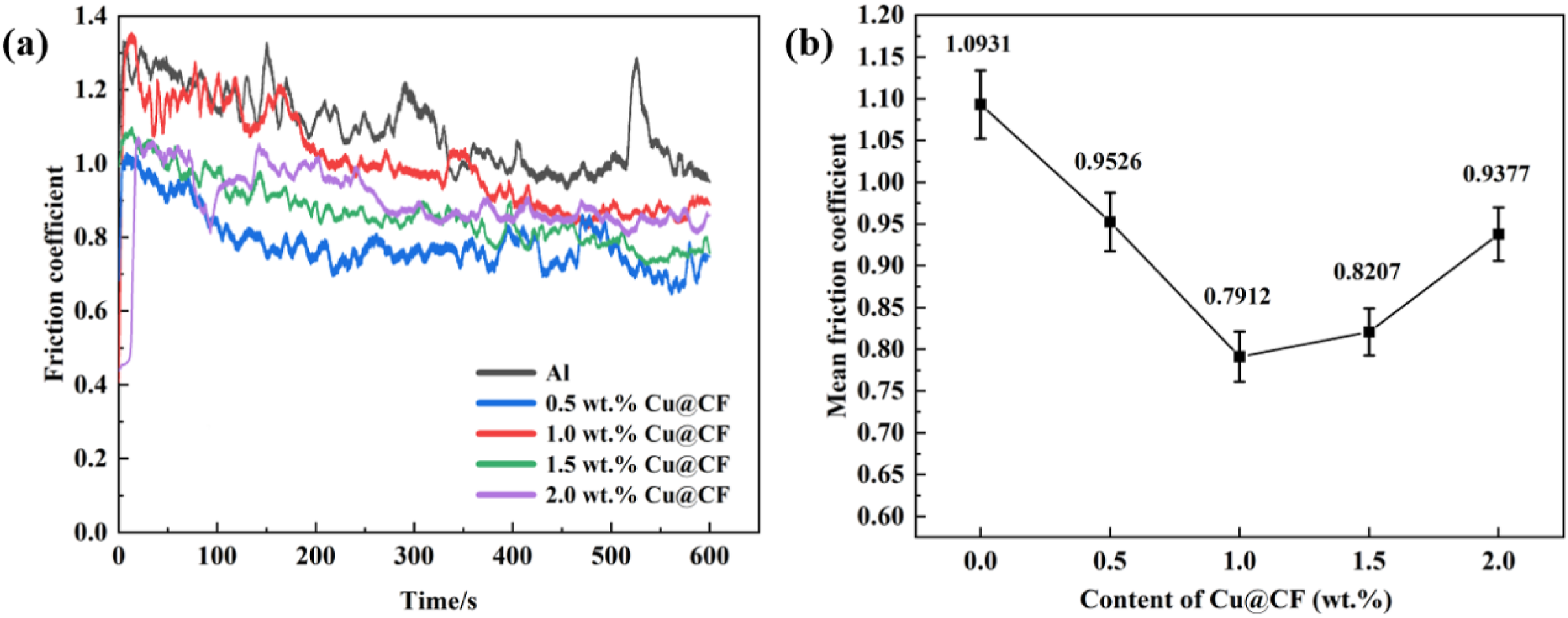
It is worth noting that the relatively high friction coefficient range (0.79–1.09) observed in this study is consistent with trends reported in the literature for dry-sliding Al-based composites reinforced with hard phases or carbonaceous reinforcements, where strong adhesive wear dominates the friction process. For example, it has been reported that the B4C-reinforced Al composites have friction coefficients in the range of 0.05–0.44 under lower applied loads due to the presence of extremely hard ceramic particles that suppress adhesive wear. 51 Likewise, Al2O3/SiC hybrid-reinforced aluminum alloys tested under lubricated conditions typically show friction coefficients as low as 0.05–0.15, as the formation of a stable lubricant film significantly reduces interfacial shear and adhesive behavior. 52 Given that our tests were conducted under more severe dry-sliding conditions (steel ball pairing, higher normal load, and longer wear track length), the friction coefficient values obtained in this study are reasonable and fall within the expected range for aluminum-matrix composites in comparable testing environments.
Figure 14 illustrates the wear morphology of the Cu@CF/Al composites with varying Cu@CF contents. As observed in Figure 14(a), numerous debris particles were generated on the worn surface of pure Al, indicating that the dominant wear mechanisms were adhesive wear and plastic deformation. Due to the soft and pliable nature of the Al matrix, the exposed Al surface rapidly formed a hard and brittle Al2O3 layer during the friction process. This oxide layer readily fractured and delaminated under repeated friction, thereby continuously exposing the underlying fresh Al and consequently generating a substantial amount of wear debris. The loose wear debris acted as third-body abrasives during repeated friction against the counter steel ball, continuously rolling and cutting the surface, thereby generating larger wear debris. As observed in Figure 14(c), at a Cu@CF content of 1.0 wt.%, the wear debris and abrasive particles on the worn surface significantly decreased. This improvement was attributed to two factors: Firstly, the introduced carbon fibers enhanced the load-bearing capacity and deformation resistance of the matrix. Secondly, during the friction process, some carbon fibers and their surface copper coatings were refined and filled into the wear tracks, facilitating the formation of a carbon-rich tribofilm. This film acted as a solid lubricant at the interface, resulting in a more stable wear process and a relatively smooth worn surface layer.
53
When the Cu@CF content was 1.5 wt.%, although the overall worn layer remained intact, local areas showed spalling pits and exposed carbon fibers were observed at the edges of these spalled regions (Figure 14(d)). This indicated that under high content conditions, local agglomeration of carbon fibers increased interfacial defects, which led to insufficient local support from the Al matrix and made the material more prone to spalling under stress concentration. While the carbon fibers were partially retained due to their high hardness, their non-uniform distribution created an uneven, irregular topography at the friction interface, thereby adversely affecting the tribological performance of the composite. At a Cu@CF content of 2.0 wt.%, the number of abrasive particles and debris significantly increased with the progression of wear, reflecting relatively severe wear phenomena in localized areas (Figure 14(e)). Worn surface morphology of Cu@CF/Al composites with different Cu@CF contents: (a) pure Al, (b) 0.5 wt.%, (c) 1.0 wt.%, (d) 1.5 wt.%, and (e) 2.0 wt.%.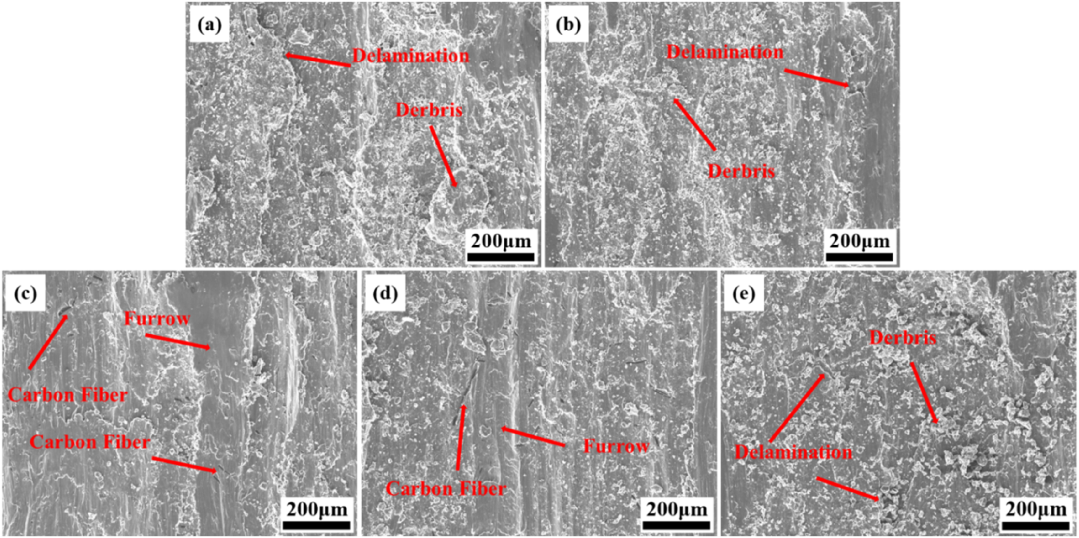
The wear mechanism analysis further supports these observations. For pure Al, severe adhesion and tearing result in the formation of large delaminated flakes, which is typical of ductile metals subjected to repeated shear and subsurface cracking. 54 Cu@CF improves hardness and load-bearing capacity, which suppresses large-scale delamination, while the fragmented carbon fibers help to interrupt continuous adhesive junctions, thereby stabilizing the wear process. Examination of worn surfaces reveals that the dominant wear mechanism in the Cu@CF/Al composites is adhesive wear accompanied by mild abrasive wear. This behavior is consistent with the damage modes widely reported for aluminum alloys under dry-sliding conditions. 55 In addition, a mechanically mixed layer (MML) is observed on samples containing 0.5–1.0 wt.% Cu@CF. This compacted tribofilm, which consists of Al debris, oxidized particles, and fragmented CF, acts as a protective barrier, reducing direct metal-to-metal contact and consequently contributing to the lower friction coefficient. However, when the Cu@CF content exceeds 1.5 wt.%, cluster-induced stress concentrations degrade the integrity of the MML, resulting in frequent cracking and peeling. This degradation of the protective layer promotes renewed adhesion and accelerates delamination, which explains the increase in the friction coefficient at higher CF contents.
The 3D wear profiles and cross-sectional profiles of Cu@CF/Al composites with different Cu@CF contents are shown in Figure 15. Both the depth and width of the wear scars first decreased and then increased with increasing Cu@CF content. As illustrated in Figure 15(e)–(f), when the Cu@CF content was increased to 1.0 wt.%, both the depth and width of the wear scar reached their minimum values, indicating a significant enhancement in the wear resistance of the composite. This was primarily attributed to the favorable dispersion of an appropriate amount of Cu@CF within the Al matrix, which improved the interfacial bonding and enhanced the load transfer, resulting in a more uniform stress distribution sustained by the matrix during the friction process. However, as the Cu@CF content continued to increase, both the depth and width of the wear scar showed a degree of enlargement (Figure 15(g)–(j)). Moreover, the 3D wear profiles exhibited irregular topography, indicating non-uniform stress distribution within the composite during the friction process (Figure 15(g) and (i)). However, when the CF content was excessive (≥1.5 wt.%), localized agglomeration led to increased interfacial defects, which prevented the Al matrix from uniformly distributing stress under frictional load and consequently degraded the overall wear resistance. Birleanu et al.
56
examined the tribological performance of carbon fiber reinforced polymer composites under boundary lubrication conditions. It was claimed that during the sliding process, the fibers were exposed on the sliding surface and bore a portion of the imposed force. Furthermore, the fibers polished the counterface material and diminished the stress at the contact interfaces between asperity peaks. 3D wear profiles and cross-sectional profiles of Cu@CF/Al composites with different Cu@CF contents: (a and b) pure Al, (c and d) 0.5 wt.%, (e and f) 1.0 wt.%, (g and h) 1.5 wt.%, and (i and j) 2.0 wt.%.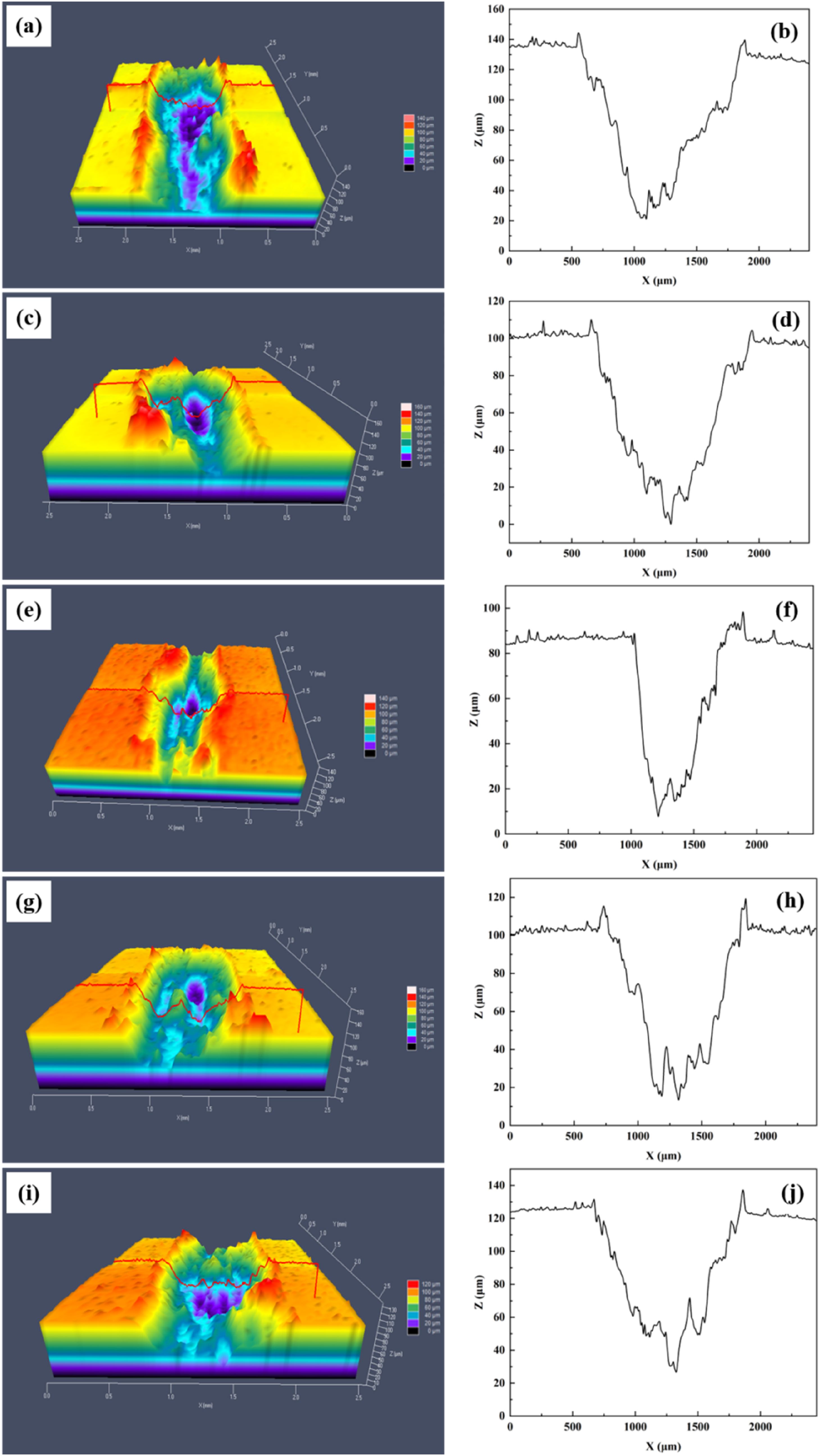
Figure 16 illustrates the wear rate curves for Cu@CF/Al composites with varying Cu@CF contents. With the increase in Cu@CF content, the wear rate of the composites first decreased and then increased. At the Cu@CF content of 1 wt.%, the wear rate achieved a minimum value of 2.79 × 10⁻² mm3/N·m. The wear rate showed a reduction of approximately 20.2% when compared to pure aluminum (3.5 × 10⁻² mm3/N·m). This improvement was attributed to the carbon fibers efficiently bearing the load, which in turn minimizes the wear on the aluminum matrix. Additionally, the copper coating improved the interfacial bonding between the CF and the Al matrix, which reduced fiber pull-out during the wear process. Wear rate of Cu@CF/Al composites with different Cu@CF contents.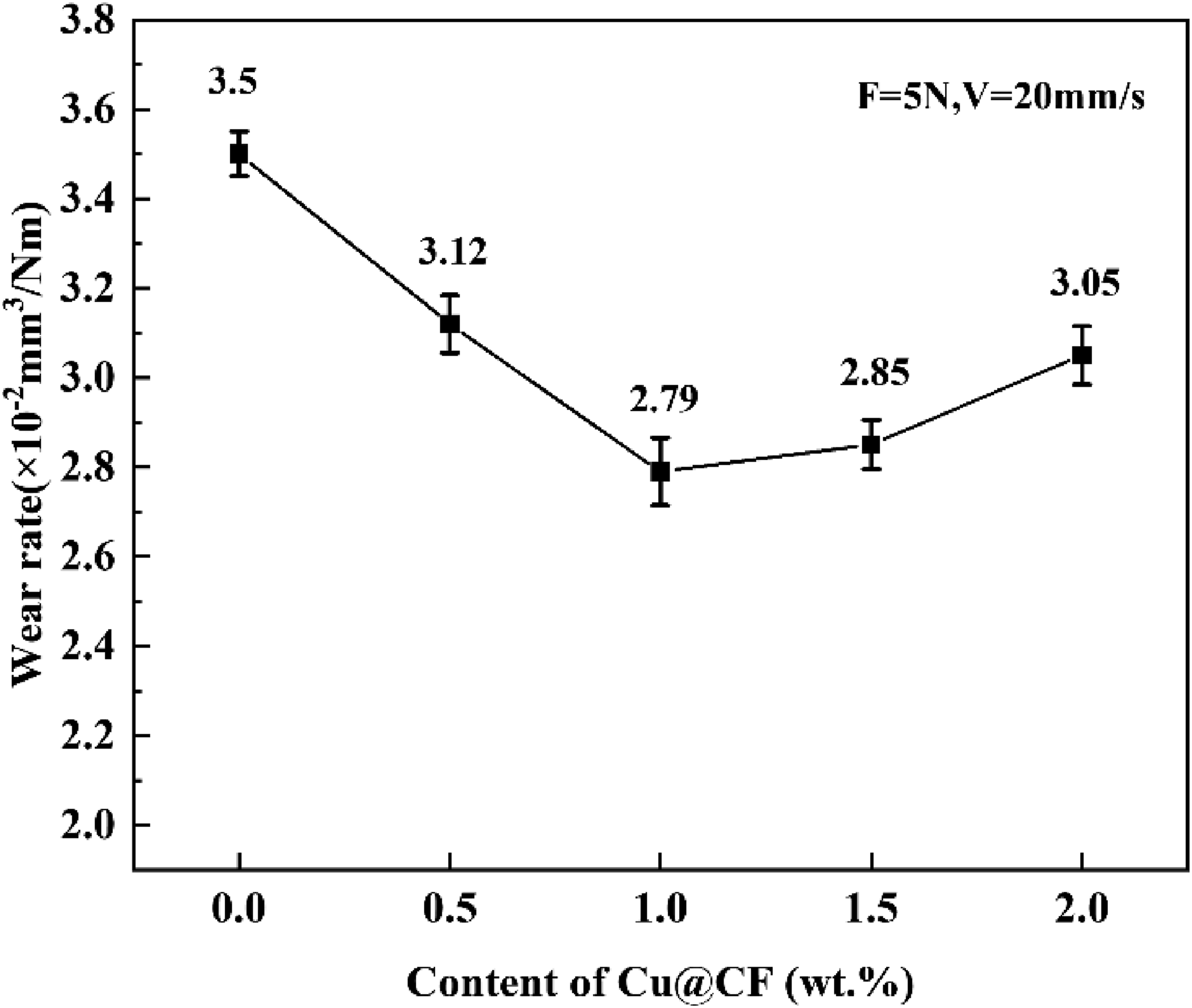
Conclusions
This study involved the preparation of Cu@CF using an electroless plating method to enhance the wettability between CF and the Al matrix. The effects of Cu@CF content on the microstructure, mechanical behavior, and tribological performance of Cu@CF/Al composites were systematically investigated, and the results were compared with typical Al-based composite systems reported in the literature. The main findings of this study are as follows: (1) The interfacial wettability was greatly enhanced by Cu@CF, and dispersed Al2Cu strengthening phases were formed during sintering as the copper coating diffused into the Al matrix. This interfacial engineering mechanism is consistent with CNT/Al and SiC/Al systems, where optimized interfaces enhance load-transfer efficiency. (2) Increasing Cu@CF content resulted in a gradual decrease in relative density (still >95%), lower CTE, and reduced thermal conductivity. This trend is consistent with observations in other carbon-reinforced Al composites, where higher reinforcement content enhances thermal stability but marginally reduces densification. (3) Brinell hardness and tensile strength first increased and then decreased with increasing Cu@CF content. The maximum hardness of 56.22 HB and tensile strength of 281.91 MPa were achieved at 1.0 wt.% Cu@CF. This peak tensile strength is comparable to CNT/Al composites, which have been reported to reach 260–275 MPa under optimized dispersion, confirming Cu@CF’s mechanical strengthening capabilities. (4) As the Cu@CF content increased, the friction coefficient and wear rate also decreased and then increased. The best wear performance was achieved at 1.0 wt.% Cu@CF, with a mean friction coefficient of 0.7912 and a wear rate of 2.79 × 10⁻² mm3/N·m. These values are consistent with the 0.4–0.9 friction coefficient range typically reported for SiC-reinforced Al composites under dry-sliding conditions, indicating that the observed tribological behavior is within the expected performance window.
Overall, the comparative analysis demonstrates that the strengthened interface induced by Cu-coating and the composition-controlled reinforcement design in this study resulted in mechanical strength and wear resistance comparable to state-of-the-art Al-based composites. These findings validate the effectiveness of Cu-based interfacial engineering and provide practical guidance for developing high-performance lightweight Al-matrix composites for aerospace and automotive applications.
Footnotes
Funding
The authors disclosed receipt of the following financial support for the research, authorship, and/or publication of this article: This work is supported by Jilin Scientific and Technological Development Program (No. 20240402054GH).
Declaration of conflicting interests
The authors declared no potential conflicts of interest with respect to the research, authorship, and/or publication of this article.
Data Availability Statement
Data sharing not applicable to this article as no datasets were generated or analyzed during the current study.